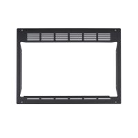
JX1095STBB - Microwaves GE - Free user manual and instructions
Find the device manual for free JX1095STBB GE in PDF.


| Product Type | Built-in microwave with trim kit |
| Brand | GE |
| Model | JX1095STBB |
| Rated Voltage | 120 V AC |
| Frequency | 60 Hz |
| Amperage | 12 A |
| Power | 1.35 kW |
| Opening Dimensions (Height) | 340 mm (13 3/8 in) min - 344 mm (13 1/2 in) max |
| Opening Dimensions (Width) | 510 mm (20 in) min - 514 mm (20 1/4 in) max |
| Opening Dimensions (Depth) | 359 mm (14 1/8 in) min with external outlet; 559 mm (22 in) with internal outlet |
| Required Power Supply | Dedicated 15-20 A circuit with grounded outlet |
| Color | Stainless steel |
| Usage | Built-in under cabinet or in a cabinet |
| Safety | Grounding required; disconnect before any installation |
| Included Accessories | Trim kit (frame, upper and lower ducts, screws) |
| Installation | Recommended by two people; basic skill level |
| Estimated Installation Time | 30 minutes to 1 hour |
| Airflow | 1 in (25 mm) clearance around frame for ventilation |
| Country of Origin | Not specified (manufactured for GE) |
Frequently Asked Questions - JX1095STBB GE
User questions about JX1095STBB GE
0 question about this device. Answer the ones you know or ask your own.
Ask a new question about this device
Download the instructions for your Microwaves in PDF format for free! Find your manual JX1095STBB - GE and take your electronic device back in hand. On this page are published all the documents necessary for the use of your device. JX1095STBB by GE.
USER MANUAL JX1095STBB GE
Installation Built-In Trim Kits Instructions
Questions? Call GE Answer Center at 800.626.2000 or Visit our Website at: GEAppliances.com
MODELS
JX1095STBB, JX1095STSS
BEFORE YOU BEGIN
Read these instructions completely and carefully.
- IMPORTANT — Save these instructions for local inspector's use.
• IMPORTANT — Observe all governing codes and ordinances. - Note to Installer – Be sure to leave these instructions with the Consumer.
- Note to Consumer – Keep these instructions for future reference.
- For easier installation and personal safety, we recommend that two people install this microwave oven.
- Unplug the microwave oven before attempting installation of this kit.
- Skill level – Installation of this appliance requires basic mechanical and electrical skills.
• Completion time – 30 minutes – 1 hour - Proper installation is the responsibility of the installer.
- Product failure due to improper installation is not covered under the Warranty.
FOR YOUR SAFETY
WARNING
Before beginning the installation, switch
power off at service panel and lock the service disconnecting means to prevent power from being switched on accidentally. When the service disconnecting means cannot be locked, securely fasten a prominent warning device, such as a tag, to the service panel.
WARNING
This oven must be plugged into a properly 120 volt receptacle as required by the Code.
TOOLS YOU WILL NEED
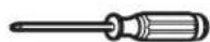
2 Phillips screwdriver

Pencil
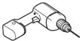
Drill with 764 " bit or #35
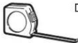
Tape measure
PARTS INCLUDED
| Part Image Part Name Quantity | ||
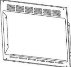
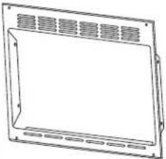 | Trim 1 | |
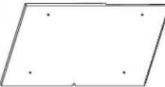 | Duct Bottom 1 | |
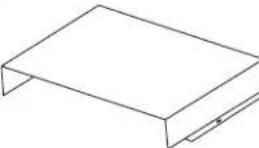
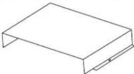 | Duct Upper 1 | |
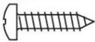 | Phillips PanHead SheetMetal Screws | 8 |
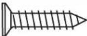 | Phillips FlatHead WoodScrews | 8 |
GROUNDING INSTRUCTIONS
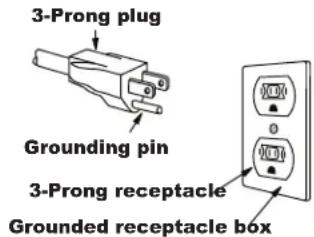
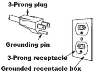
This appliance must be grounded. In the event of an electrical short circuit, grounding reduces the risk of electric shock by providing an escape wire for the electric current. This appliance is equipped with a cord having a grounding wire with a grounding plug. The plug must be plugged into an outlet that is properly installed and grounded. Consult a qualified electrician or serviceman if the grounding instructions are not completely understood, or if doubt exists as to whether the appliance is properly grounded.
WARNING
Improper use of the grounding plug can result in a risk of electric shock. Do not use an extension cord. If the power supply cord is too short, have a qualified electrician or serviceman install an outlet near the appliance.
Permanent and Correct Installation
ELECTRICAL REQUIREMENTS
Product rating is 120 volts AC, 60 Hertz, 12 amps and 1.35 kilowatts. This product must be connected to a supply circuit of the proper voltage and frequency. Wire size must conform to the requirements of the National Electrical Code or the prevailing local code for this kilowatt rating. The power supply cord and plug should be brought to a separate 15 to 20 ampere branch circuit single grounded outlet. The outlet box should be located in the cabinet above the oven. The outlet box and supply circuit should be installed by a qualified electrician and conform to the National Electrical Code or the prevailing local code.
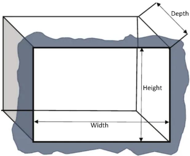
CUTOUT DIMENSIONS
| Minimum Maximum | ||
| Height | 13 3/8" (340 mm) | 13 1/2" (344 mm) |
| Width 20" (510 mm) | 20 1/4" (514 mm) | |
| Depth 14 1/8" (359 mm) | N/A | |
* Min. depth with receptacle outside cabinet 19/2 Min. depth with receptacle inside cabinet 22"
CAUTION
This trim kit uses air flow from the top and bottom of the trim frame. Blocking the air flow can cause the microwave to function improperly and may cause damage to the microwave.
Allow a 1" clearance beyond the edge of the Trim Frame to provide proper air flow.
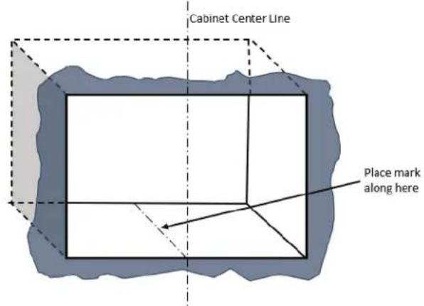
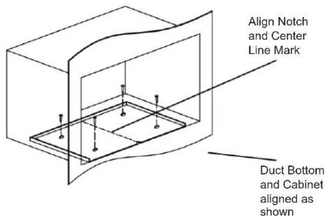
1 MARK CENTER LINE FOR DUCT BOTTOM
Locate the center line of the front of the cabinet microwave cutout and draw a corresponding center line on the bottom deck of the cabinet.
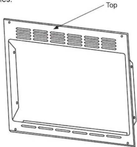
3 REVIEW THE TRIM
Take Trim and check it. The top is recognized as the wider side with 24 vent holes and the bottom has 6 vent holes.
2 LOCATE AND INSTALL THE DUCT BOTTOM
Place the Duct Bottom as shown in the cabinet. The front edge of the Duct Bottom should match with the front edge of the Cabinet and the center notch is directly aligned with the center line created in Step 1. Using the Duct Bottom as a template, drill pilot holes at the 4 screw holes. Mount the Duct Bottom using 4 of the supplied Wood Screws.
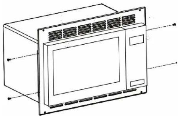
4 MOUNT THE TRIM
Mount the Trim to the Microwave as shown. Use 4 of the supplied Sheet Metal Screws to fasten the Trim at points indicated. After mounted avoid using the trim to support the weight of the microwave.
natural_image
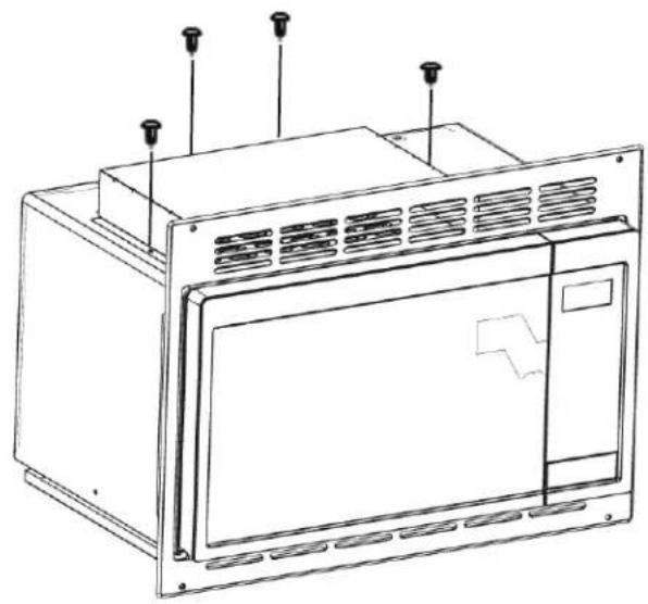
Line drawing of a microwave oven with ventilation grilles and mounting holes (no text or symbols)5 MOUNT THE DUCT UPPER
Mount the Duct Upper on the top of the outer case of the Microwave cover. Use the remaining 4 Sheet Metal Screws to fasten the Duct Upper at points indicated.
natural_image
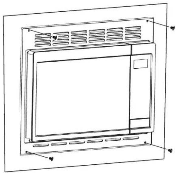
Line drawing of a microwave oven with mounting points and ventilation grilles (no text or symbols)7 MOUNT THE MICROWAVE OVEN ASSEMBLY
Mount the Assembly to the Cabinet. Using the Trim as a template, drill pilot holes at the 4 screw holes. Use the remaining 4 Wood Screws to fasten the Trim at the points indicated.
natural_image
Line drawing of a microwave oven with ventilation grilles and control panel (no text or symbols)6 INSTALL THE MICROWAVE OVEN ASSEMBLY
Plug the power cord in the wall receptacle. Slide the microwave oven assembly gently into the cabinet, using care not to pinch the power cord. Be sure to keep the assembly centered as it slides back.
8 REPLACE ANY LOOSE ITEMS
Your trim kit is now fully installed. Replace any loose items that were removed from the inside of the microwave oven.
Keep these installation instructions for future reference.
Replace house fuse or close circuit breaker to restore power at the service panel.
JX1095STBB, JX1095STSS
AVANT DE COMMENCER
Permanent and Correct Installation
EXIGENCES ÉLECTRIQUES
3 EXAMINER LA GARNITURE
natural_image
Line drawing of a microwave oven with ventilation grilles and mounting feet (no text or symbols)5 MONTER LA PARTIE SUPÉRIEURE DU CONDUIT
natural_image
Line drawing of a microwave oven with mounting points and ventilation grilles (no text or symbols)natural_image
Line drawing of a front-mounted kitchen appliance with ventilation grilles and control panel (no text or symbols)8 REPLACER TOUT ARTICLE LIBRE
JX1095STBB, JX1095STSS
ANTES DE COMENZAR
Before beginning the installation,
switch power off at service panel and lock the service disconnecting means to prevent power from being switched on accidentally. When the service disconnecting means cannot be locked, securely fasten a prominent warning device, such as a tag, to the service panel.
ADVERTENCIA
| Part Image Part Name Quantity | ||
 | Trim 1 | |
 | Duct Bottom 1 | |
 | Duct Upper 1 | |
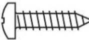 | Phillips Pan Head Sheet Metal Screws | 8 |
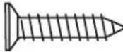 | Phillips Flat Head Wood Screws | 8 |
3 REVISE EL MARCO
natural_image
Line drawing of a microwave oven with ventilation grilles and mounting brackets (no text or symbols)5 MONTE EL CONDUCTO MÁS ARRIBA
natural_image
Line drawing of a microwave oven with mounting points and ventilation grilles (no text or symbols)7 MONTE EL ENSAMBLE DEL HORNO MICROONDAS
natural_image
Line drawing of a microwave oven with ventilation grilles and control panel (no text or symbols)6 INSTALE EL ENSAMBLE DEL HORNO MICROONDAS

- Installation Built-In Trim Kits Instructions
- MODELS
- BEFORE YOU BEGIN
- FOR YOUR SAFETY
- WARNING
- TOOLS YOU WILL NEED
- Phillips screwdriver
- GROUNDING INSTRUCTIONS
- ELECTRICAL REQUIREMENTS
- CAUTION
- MARK CENTER LINE FOR DUCT BOTTOM
- REVIEW THE TRIM
- LOCATE AND INSTALL THE DUCT BOTTOM
- MOUNT THE TRIM
- MOUNT THE DUCT UPPER
- MOUNT THE MICROWAVE OVEN ASSEMBLY
- INSTALL THE MICROWAVE OVEN ASSEMBLY
- REPLACE ANY LOOSE ITEMS
- AVANT DE COMMENCER
- EXIGENCES ÉLECTRIQUES
- EXAMINER LA GARNITURE
- MONTER LA PARTIE SUPÉRIEURE DU CONDUIT
- REPLACER TOUT ARTICLE LIBRE
- ANTES DE COMENZAR
- ADVERTENCIA
- REVISE EL MARCO
- MONTE EL CONDUCTO MÁS ARRIBA
- MONTE EL ENSAMBLE DEL HORNO MICROONDAS
- INSTALE EL ENSAMBLE DEL HORNO MICROONDAS
Brand : GE
Model : JX1095STBB
Category : Microwaves