TMS152 - Speaker Turbosound - Free user manual and instructions
Find the device manual for free TMS152 Turbosound in PDF.
| Product type | Passive 2-way loudspeaker |
| Brand | Turbosound |
| Model | TMS152 |
| Category | Sound reinforcement speaker |
| Dimensions (H x W x D) | Approximately 700 x 450 x 450 mm |
| Weight | Approximately 28 kg |
| Power | Passive (requires external amplifier) |
| Nominal impedance | 8 ohms |
| Power handling (program) | 600 W |
| Frequency response | 55 Hz - 20 kHz |
| Sensitivity (1W/1m) | 98 dB |
| Woofer | 1 x 15" (381 mm) |
| Tweeter | 1 x 1" (25 mm) compression driver |
| Connectors | 2 x Neutrik Speakon NL4 |
| Enclosure material | Birch plywood with polyurethane coating |
| Protective grille | Steel grille with acoustic foam |
| Intended use | Live sound, fixed installation |
| Maintenance and cleaning | Clean with a dry cloth; do not use liquid or abrasive products |
| Safety | Do not open the enclosure; risk of electric shock; disconnect before maintenance |
| Spare parts and repairability | Repair by qualified personnel only; parts available through authorized network |
| General information | Limited warranty, see music-group.com/warranty |
Frequently Asked Questions - TMS152 Turbosound
User questions about TMS152 Turbosound
0 question about this device. Answer the ones you know or ask your own.
Ask a new question about this device
Download the instructions for your Speaker in PDF format for free! Find your manual TMS152 - Turbosound and take your electronic device back in hand. On this page are published all the documents necessary for the use of your device. TMS152 by Turbosound.
USER MANUAL TMS152 Turbosound
natural_image
Four-panel black-and-white photo collage showing a crowded cinema lobby, a crowd celebrating with raised fists, a vintage TV studio, and a cheering crowd holding up a smartphone (no visible text or symbols)Venue/Madrid
TVX/TMS ^SERIES
TVX122M/TVX152/TVX118B/TMS122M/TMS152/
TMS153/TMS118B/TMS218B
Full Range Loudspeakers and Subwoofers for
Portable PA and Installation Applications
Quickstart Guide
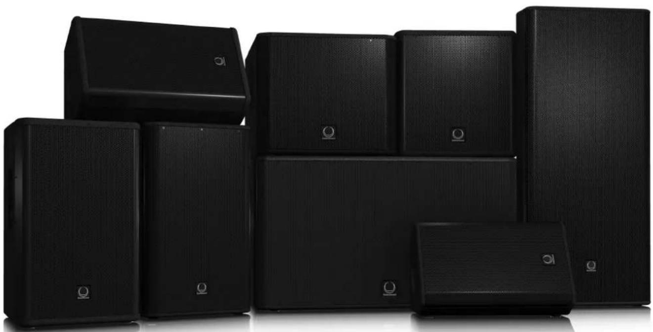
natural_image
Collection of black audio/video speakers arranged in a cluster (no visible text or labels)
text_image
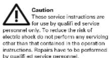
EN Important Safety Instructions CAUTION RISK OF ELECTRIC SHOCK DO NOT OPEN ATTENTION RESUME ELECTRICATION! WE HAS QUVER? Terminals marked with this symbol carry electrical current of sufficient magnitude to constitute risk of electric shock. Use only high quality commercially available speaker cables with plugs pre-installed. All other installation or modified cation should be performed only by qualified personnel.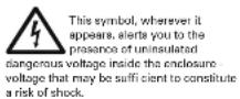


text_image
1. Read these instructions. 2. Keep these instructions. 3. Head all warnings. 4. Follow all instructions. 5. Do not use this apparatus near water. 6. Clean only with dry cloth. 7. Do not block any ventilation openings. Install in accordance with the manufacturer's instructions. 8. Do not install near any heat sources such as radiators, heat registers, staves, or other apparatus (including amplifiers) that produce heat.-
Do not defeat the safety purpose of the polarized or grounding-type plug. A polarized plug has two blades with one wider than the other. A grounding-type plug has two blades and a third grounding prong. The wide blade or the third prong are provided for your safety. If the provided plug does not fit into your outlet, consult an electrician for replacement of the obsolete outlet.
-
Protect the power cord from being walked on or pinched particularly at plugs, convenience receptacles, and the point where they exit from the apparatus.
-
Use only attachments/accessories specified by the manufacturer.

- Use only with the cart, stand, tripod, bracket, or table specified by the manufacturer, or sold with the apparatus. When a cart is used,
moving the cart/apparatus combination to avoid injury from tip-over. 13. Unplug this apparatus during lightning storms or when unused for long periods of time.
-
Refer all servicing to qualified service personnel. Servicing is required when the apparatus has been damaged in any way, such as power supply cord or plug is damaged, liquid has been spilled or objects have fallen into the apparatus, the apparatus has been exposed to rain or moisture, does not operate normally, or has been dropped.
-
The apparatus shall be connected to a MAINS socket outlet with a protective earthing connection.
-
Where the MAINS plug or an appliance coupler is used as the disconnect device, the disconnect device shall remain readily operable.

- Correct disposal of this product: This symbol indicates that this product must not be disposed of with household waste, according to the WEEE Directive (2012/19/EUI) and your national law.
This product should be taken to a collection center licensed for the recycling of waste electrical and electronic equipment IEEE. The mishandling of this type of waste could have a possible negative impact on the environment and human health due to potentially hazardous substances that are generally associated with EEE. At the same time, your cooperation in the correct disposal of this product will contribute to the effi client use of natural resources. For more information about where you can take your waste equipment for recycling, please contact your local city off cc, or your household waste collection service.
LEGAL DISCLAIMER
MUSIC Group accepts no liability for any loss which may be suffered by any person who relies either wholly or in part upon any description, photograph, or statement contained herein. Technical specifications, appearances and other information are subject to change without notice. All trademarks are the property of their respective owners. MIDAS, KLARK TEKNIK, TURBOSOUND, BEHRINGER, BUGERA and DDA are trademarks or registered trademarks of MUSIC Group IP Ltd. © MUSIC Group IP Ltd. 2014 All rights reserved.
LIMITED WARRANTY
For the applicable warranty terms and conditions and additional information regarding MUSIC Group's Limited Warranty, please see complete details online at music group.com/warranty.

BESCHRÄNKTE GARANTIE
Thank you for choosing a TURBOSOUND loudspeaker product for your application. If you would like further information about this or any other product, please visit our website at turbosound.com.
Unpacking the Loudspeaker
After unpacking the unit, please check carefully for damage. If damage is found, please notify your supplier at once. You, the consignee, must instigate any claim. Please retain all packaging in case of future return shipment.
System Requirements
TVX122M, TVX152, TMS122M, TMS152 and TMS153 are switchable passive / bi-amp 2-way loudspeakers. Passive operation (full range or with a subwoofer) requires 1 amplifier channel and 1 controller channel. The input signal is divided between the low-frequency and high-frequency drivers internally with a passive crossover.
Bi-amp operation (full range or with a subwoofer) requires 2 amplifier channels and 2 controller channels, one for low frequencies one for high frequencies. The input signal is divided between the low frequency and high frequency drivers in the controller and the individual amplified signals are fed to the speaker input.
TVX118B, TMS118B and TMS218B subwoofers have a switchable input to allow operation with the satellite speakers using a single four core cable run. Operation requires 1 amplifier channel and 1 controller channel.
Correct controller settings for all models operation and with subwoofers can be downloaded from turbosound.com, and are also available as presents for the LMS series controllers. To avoid wasting amplifier power, you should use heavy-duty speaker cable with a minimum wire size of 1.5 mm² (16 AWG), and preferably 2.5 mm² (14 AWG) for longer runs. For the TMS153 and TMS218B, use 4.5 mm² (10-12 AWG) where possible. For extreme cable lengths, be aware of cable impedance and resistive losses. Always observe the correct polarity.
The TVX122M and TMS122M 2-way systems double effectively as wedge monitors. The TVX122M and the TMS122M both provide 30° and 60° wedge angles from the stage.
EN
Amplifi er Considerations
The TVX and TMS series loudspeakers are optimized for use with the TURBOSOUND T series amplifiers with the LMS series controllers. A full range of DSP settings to suit any configuration are provided for download on the TURBOSOUND website. The use of third party amplification and processing is only advised using the matrix of manual settings as well as the limiter calculator provided on the TURBOSOUND website. The TVX and TMS series loudspeaker enclosures should be driven by high quality power amplifiers designed for true professional use. Power amplifiers should be capable of delivering long term broadband power equal to half the loudspeaker's peak power rating at its stated nominal impedance. The use of underpowered amplifiers must be avoided as heavily clipped signals can cause permanent loudspeaker damage. Limiters, crossovers and equalisation points must be set in accordance with the settings provided on the TURBOSOUND website. This will ensure the optimum sound quality and long-term reliability as well as protection from damage.
Neutrik speakON* NL4 locking input connector(s) are provided, allowing options for input and link, passive, and bi-amp operation.
| Model TVX122M TVX182 TVX1180 | |||||||
| Mode Passive Swing LF Bi-amp HF Passive Swing LF Bi-amp HF Sub | |||||||
| Impedance | BΩ | BΩ | BΩ | BΩ | BΩ | BΩ | |
| Minimum Amplifier | Continuous RMS | 500 W | 600 W | 400 W | 500 W | 600 W | 400 W |
| Power | Peak | 2000 W | 2000 W | 2000 W | 2000 W | 2000 W | 2400 W |
| Model | TMS112M | TMS152 | |||||
| Mode | Passive Diamp LT Di amp | Hi Passive Di amp LT Di amp | Hi | ||||
| Impedance | B (i) | B (i) | B (i) | B (i) | B (i) | B (i) | |
| MinimumAmplifierPower | ContinuousHMIS | 800 W | 300 W | 75 W | 900 W | 800 W | 75 W |
| Peak | 3200 W | 3200 W | 750 W | 3200 W | 3200 W | 750 W | |
| Model | TMS 153 | TMS118B | TMS218B | |||
| Mode | Passive | Bi amp LF | Bi amp HF | Sub | Sub | |
| Impedance | 4 Ω | 4 Ω | 6 Ω | 8 Ω | 4 Ω | |
| Minimum Amplifier Power | Continuous RMS | 1200 W | 1200 W | 75 W | 800 W | 1600 W |
| Peak | 4800 W | 4800 W | 750 W | 3200 W | 6400 W | |
Connections
Models: TVX122M, TVX152, TMS122M, TMS152, TMS153
| Mode | Connector | Internal Schematic |
| Passive |  | 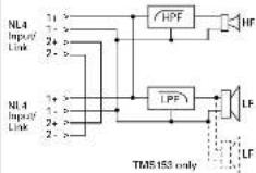 |
| Bi-Amp |  | 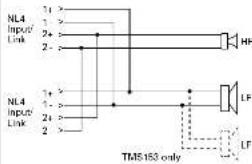 |
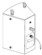
Models: TVX118B, TMS118B, TMS218B
| Mode | Back Panel | Connector | Internal Schematic |
| NormalOperation1+/1- |  | speakON® NL4 | 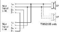 |
 | |||
| 4-WireSingle CableRunOperation2+/2- | speakON® NL4 | 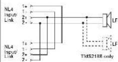 |
Mounting and Fixing
TVX and TMS full-range series cabinets are designed with multiple internal rigging points to suit many possible mounting methods in permanent installations.
Suspending with Eyebolts
TVX and TMS cabinets can be suspended using optional eyebolts coupled to the internal rigging points provided on the top, bottom and sides and back. The simplest method is to use the two rigging points on the top and a single pull-back rigging point in the centre of the rear panel.
Remove the appropriate countersunk screws and replace them with shoulder eyebolts, which must have a thread length of at least 18 mm. Use the rear rigging point to angle the cabinet for optimum room coverage. Cabinets may be hung upside down if required.
IMPORTANT NOTE: The mounting of a permanently installed sound system may be dangerous unless undertaken by qualified personnel with the required experience and certification to perform the necessary tasks.
Walls, floors or ceilings must be capable of safely and securely supporting the actual load. The mounting accessory used must be safely and securely fixed both to the loudspeaker and to the wall, floor or ceiling.
When mounting rigging components on walls, floors or ceilings, ensure that all fixings and fasteners used are of an appropriate size and load rating. Wall and ceiling claddings, and the construction and composition of walls and ceilings, all need to be taken into account when determining whether a particular fixing arrangement can be safely employed for a particular load. Cavity plugs or other specialist fixings, if required, must be of an appropriate type, and must be fitted and used in accordance with the maker's instructions.
The operation of your speaker cabinet as part of a flown system, if installed incorrectly and improperly, can potentially expose persons to serious health risks and even death. In addition, please ensure that electrical, mechanical and acoustic considerations are discussed with qualified and certified (by local state or national authorities) personnel prior to any installation or II ying.
Make sure that speaker cabinets are set up and flown by qualified and certified personnel only, using dedicated equipment and original parts and components delivered with the unit. If any parts or components are missing please contact your dealer before attempting to set up the system.
Be sure to observe the local, state and other safety regulations applicable in your country. MUSIC Group, including the MUSIC Group companies listed on the enclosed "Service Information Shoot", assumes no liability for any damage or personal injury resulting from improper use, installation or operation of the product. Regular checks must be conducted by qualified personnel to ensure that the system remains in a secure and stable condition. Make sure that, where the speaker is flown, the area underneath the speaker is free of human traffic. Do not fly the speaker in areas that can be entered or used by members of the public.
Speakers create a magnetic field, even if not in operation. Therefore, please keep all materials that can be affected by such fields (discs, computers, monitors, etc) at a safe distance. A safe distance is usually between 1 and 2 metres.
14 TVX/TMS Series Quick Start Guide
EN Technical Specifications
| TVX122M TVX152 TMS122M TMS152 TMS153 | |||||
| System | |||||
| Frequency response | 85 Hr - 20 kHz +3 dB55 Hr - 20 kHz - 10 dB | 80 Hr - 20 dBr +3 dB50 Hr - 20 dBr - 10 dB | 85 Hr - 18 dBr -3 dB50 Hr - 20 dBr - 10 dB | 55 Hz - 20 kHz -3 dB45 Hz - 20 kHz - 10 dB | 50 Hz - 20 kHz +3 dB37 Hz - 20 kHz - 10 dB |
| Nominal dispersion | 70° H x 70° V @-6 dB points | 70° H x 70° V @-6 dB points | 90° H x 50° V @-6 dB points | 70° H x 50° V @-6 dB points | 75° H x 50° V @-6 dB points |
| Directivity factor (IQ) | 9.4 3.4 10.4 12.8 12.8 | ||||
| Directivity index (DI) | 9.7 8.7 10.2 11.1 11.1 | ||||
| Power handling (IEC) | |||||
| Passive | 500 W continuous,2,000 W peakLF: 500 Wcontinuous,2,000 W peakHF: 40 WWincontinuous,160 W peak | 500 W continuous,2,000 W peakLF: 500 Wcontinuous,2,000 W peakHF: 40 WWincontinuous,160 W peak | 800 W continuous,3,200 W peakLF: 800 Wcontinuous,3,200 W peakHF: 75 Wcontinuous,300 W peak | 800 W continuous,3,200 W peakLF: 800 Wcontinuous,3,200 W peakHF: 75 Wcontinuous,300 W peak | 1,200 W continuous,4,800 W peakLF: 1,200 Wcontinuous,4,800 W peakHF: 75 WWincontinuous,300 W peak |
| Sensitivity | 97 dB (1 W @ 1 m): 97 dB (1 W @ 1 m): 97 dB (1 W @ 1 m): 99 dB (1 W @ 1 m): 99 dB (1 W @ 1 m): 99 dB (1 W @ 1 m): 99 dB (1 W @ 1 m): 99 dB (1 W @ 1 m): 99 dB (1 W @ 1 m): 99 dB (1 W @ 1 m): 99 dB (1 W @ 1 m): 99 dB (1W) | ||||
| Maximum SPL | |||||
| Passive | 124 dB continuous,130 dB peakLF: 124 dBcontinuous,130 dB peakHF: 122 dBcontinuous,128 dB peak | 124 dB continuous,130 dB peakLF: 124 dBcontinuous,130 dB peakHF: 122 dBcontinuous,128 dB peak | 125 dB continuous,131 dB peakLF: 125 dBcontinuous,131 dB peakHF: 128 dBcontinuous,134 dB peak | 125 dB continuous,132 dB peakLF: 126 dBcontinuous,132 dB peakHF: 128 dBcontinuous,134 dB peak | 130 dB continuous,136 dB peakLF: 130 dBcontinuous,136 dB peakHF: 128 dBcontinuous,134 dB peak |
| Impadance | |||||
| Passive | 8 Ω | 8 Ω | 8 Ω | 8 Ω | 4 Ω |
| BIamp | LF: 8.0HF: 6 Ω | LF: 8.0HF: 6 Ω | LF: 8.0HF: 6 Ω | LF: 8.0HF: 6 Ω | LF: 4.0HF: 8 Ω |
| Crossover type | Passive / BIamp,switchable | Passive / BIamp,switchable | Passive / BIamp,switchable | Passive / BIamp,switchable | Passive / BIamp,switchable |
| Components | 1 x 12" (136 mm)LF driver1 x 1" (25 mm) HFcompression driver | 1 x 15" (134 mm)LF driver1 x 1" (25 mm) HFcompression driver | 1 x 12" (136 mm)LF driver1 x 1.4" (36 mm) HFcompression driver | 1 x 15" (394 mm)LF driver1 x 1.4" (36 mm) HFcompression driver | 2 x 15" (394 mm)LF driver1 x 1.4" (36 mm) HFcompression driver |
| Enclosure | |||||
| Connectors | 2 x NeutrikspeakON* NL4 | 2 x NeutrikspeakON* NL4 | 2 x NeutrikspeakON* NL4 | 2 x NeutrikspeakON* NL4 | 2 x NeutrikspeakON* NL4 |
| Wiring | |||||
| Passive | Pins 1+/- 1- Input,Pins 2+/- 2- link | Pins 1+/- 1- Input,pins 2+/- 2- link | Pins 1+/- 1- Input,pins 2+/- 2- link | Pins 1+/- 1- Input,pins 2+/- 2- link | Pins 1+/- 1- Input,pins 2+/- 2- link |
| BIamp | Pins 1+/- 1-LF,Pins 2+/- 2-HF | Pins 1+/- 1-LF,pins 2+/- 2-HF | Pins 1+/- 1-LF,pins 2+/- 2-HF | Pins 1+/- 1-LF,pins 2+/- 2-HF | Pins 1+/- 1-LF,pins 2+/- 2-HF |
| Dimensions (HWD) | 634 x 381 x 370 mm(25.0 x 15.0 x 14.6") | 701 x 432 x 470 mm(27.6 x 17.0 x 18.5") | 566 x 349 x 283 mm(22.3 x 13.7 x 11.1") | 716 x 432 x 406 mm(28.2 x 17.0 x 16.0") | 1219 x 533 x 508mm(48.8 x 21.8 x 20.0") |
| Net weight | 21.1 kg (46.5 lbs): 26.4 kg (58.1 lbs): 18.2 kg (40.0 lbs): 27.7 kg (61.0 lbs): 48.9 kg (103.5 lbs): | ||||
| Construction | 15 mm (4/4" birchplywood | 15 mm (4/4" birchplywood | 15 mm (4/4" birchplywood | 15 mm (4/4" birchplywood | 15 mm (4/4" birchplywood |
| Finish | Semi matt blackpaint | Semi matt blackpaint | Semi matt blackpaint | Semi matt blackpaint | Semi matt blackpaint |
| Grille | Powder-coatedperforated steel | Powder-coatedperforated steel | Powder-coatedperforated steel | Powder-coatedperforated steel | Powder-coatedperforated steel |
| Flying hardware | M10 x 12 M10 x 12 M10 x 2 M10 x 12 | ||||
15
| TVX118B | TMS118B | TMS218B | |
| System | |||
| Frequency response | 40 Hz - 200 Hz +3 dB32 Hz - 200 Hz - 10 dB | 38 Hz - 200 Hz +3 dB32 Hz - 200 Hz - 10 dB | 33 Hz - 200 Hz +3 dB27 Hz - 200 Hz - 10 dB |
| Nominal dispersion | Half space | Half space | Half space |
| Power handling (IECI) | 600 W continuous, 2,400 W peak | 800 W continuous, 3,200 W peak | 1,600 W continuous, 6,400 W peak |
| Sensitivity | 97 dB | 97 dB | 100 dB |
| Maximum SPL | 125 dB continuous, 131 dB peak | 126 dB continuous, 132 dB peak | 132 dB continuous, 138 dB peak |
| Impedance | 4 Ω | 8 Ω | 4 Ω |
| Components | 1 x 18" 1460 mm LF driver | 1 x 18" 1460 mm LF driver | 2 x 18" 1460 mm LF drivers |
| Encluence | |||
| Connectors | 2 x Neutrik speakON® NL4 | 2 x Neutrik speakON® NL4 | 2 x Neutrik speakON® NL4 |
| Wiring | |||
| Switch position 1x1/1-Switch position 2x2- | Pins 1+ / 1-input, pins 2+ / 2-linkPins 1+ / 1-link, pins 2+ / 2-Input | Pins 1+ / 1-input, pins 2+ / 2-linkPins 1+ / 1-link, pins 2+ / 2-Input | Pins 1+ / 1-input, pins 2+ / 2-linkPins 1+ / 1-link, pins 2+ / 2-Input |
| Dimensions (HWD) | 553 x 533 x 700 mm(21.8 x 21.0 x 27.6") | 513 x 597 x 750 mm(120.2 x 235.5 x 29.5") | 1067 x 602 x 938 mm(142.0 x 23.7 x 33.0") |
| Net weight | 34.8 kg (76.8 lbs) | 39.8 kg (87.8 lbs) | 82.3 kg (181.4 lbs) |
| Construction | 18 mm (1⁄2",) birch plywood | 18 mm (1⁄2",) birch plywood | 18 mm (1⁄2",) birch plywood |
| Finish | Semi-mast black paint Semi-mast black paint Semi-matt black paint | ||
| Grille | Powder-coated perforated steel | Powder-coated perforated steel | Powder-coated perforated steel |
| Flying hardware | — | — | — |
| Accessories | |||
| TPOLE80-20, 60 cm pole witha 20 mm threadTPOLE30-20, 90 cm pole witha 20 mm threadTPOLE120-20, 120 cm pole witha 20 mm thread | |||
EN
16 TVX/TMS Series Quick Start Guide
EN Other important information
EN Important information
-
Register online. Please register your new MUSIC Group equipment right after you purchase it by visiting turbosound.com. Registering your purchase using our simple online form helps us to process your repair claims more quickly and efficiently. Also, read the terms and conditions of our warranty, if applicable.
-
Malfunction. Should your MUSIC Group Authorized Reseller not be located in your vicinity, you may contact the MUSIC Group Authorized Full tier for your country listed under "Support" at turbosound.com. Should your country not be listed, please check if your problem can be dealt with by our "Online Support" which may also be found under "Support" at turbosound.com. Alternatively, please submit an online warranty claim at turbosound.com BEFORE returning the product.
-
Power Connections. Before plugging the unit into a power socket, please make sure you are using the correct mains voltage for your particular model. Faulty fuses must be replaced with fuses of the same type and rating without exception.