
EB7260 - Lighting ECCO - Free user manual and instructions
Find the device manual for free EB7260 ECCO in PDF.

| Product Type | LED Warning Light Bar |
| Brand | ECCO |
| Model | EB7260 (5580/5585/5587 series) |
| Dimensions (L x W x H) | 15 x 9 x 2.5 in (38.1 x 22.9 x 6.4 cm); variants up to 3.1 in (7.9 cm) height |
| Weight | Permanent mount: 3.4 lb (1.54 kg); magnetic: 4.0 lb (1.81 kg); vacuum: 5.7 lb (2.59 kg) |
| Power Supply | 12-24 V DC, max current 2.7 A (5580) or 5.1 A (5585) |
| Max Power | 35 W (5580) / 66 W (5585) |
| Operating Temperature | -30°C to +50°C (-22°F to +122°F) |
| Flash Patterns | Double, quadruple, quintuple, rotation, random, selectable via yellow wire |
| Available Colors | Amber, blue, red, green, white, combinations |
| Mounting Options | Permanent, magnetic, magnetic vacuum |
| Lens Material | Optic (5580/5585) or bare reflector (5587) |
| Protection Rating | Not specified, but designed for outdoor use |
| Maintenance and Cleaning | Clean with soft, non-abrasive cloth; avoid excessive moisture |
| Safety | Installation by authorized personnel; comply with local laws; do not obstruct light; disconnect before maintenance |
| Spare Parts and Repairability | Lenses, O-rings, magnets, suction cups, cables; repair by manufacturer under warranty |
| Warranty | 36 months limited |
Frequently Asked Questions - EB7260 ECCO
User questions about EB7260 ECCO
0 question about this device. Answer the ones you know or ask your own.
Ask a new question about this device
Download the instructions for your Lighting in PDF format for free! Find your manual EB7260 - ECCO and take your electronic device back in hand. On this page are published all the documents necessary for the use of your device. EB7260 by ECCO.
USER MANUAL EB7260 ECCO
5580 Series - Reflex™ LED Minibars provide a compact yet powerful warning solution that offers the flexibility of either permanent, magnet, or vacuum-magnet mounting. All models feature 12-24 VDC operation and use LED reflector technology to maximize light output, offering multiple flash patterns including double, quad quint, rotate and random. 5587 models have no lens optics, distributing light directly from the LED reflectors while 5580 & 5585 models feature lenticular lens optics to provide more diffused light dispersion.

natural_image
Product image of a REFLEX LED light fixture with transparent casing and internal components (no text or symbols on main body)
WARNING!
Failure to install or use this product according to manufacturers recommendations may result in property damage, serious injury, and/or death to those you are seeking to protect!

Do not install and/or operate this safety product unless you have read and understand the safety information contained
- Proper installation combined with operator training in the use, care, and maintenance of emergency warning devices are essential to ensure the safety of you and those you are seeking to protect.
- Exercise caution when working with live electrical connections.
- This product must be properly grounded. Inadequate grounding and/or shorting of electrical connections can cause high current arcing, which can cause personal injury and/or severe vehicle damage, including fire.
- Proper placement and installation are vital to the performance of this warning device. Install this product so that output performance of the system is maximized and the controls are placed within convenient reach of the operator so that s/he can operate the system without losing eye contact with the roadway.
- Do not install this product or route any wires in the deployment area of an air bag. Equipment mounted or located in an air bag deployment area may reduce the effectiveness of the air bag or become a projectile that could cause serious personal injury or death. Refer to the vehicle owner's manual for the air bag deployment area. It is the responsibility of the user/operator to determine a suitable mounting location ensuring the safety of all passengers inside the vehicle particularly avoiding areas of potential head impact.
- It is the responsibility of the vehicle operator to ensure during use that all features of this product work correctly. In use, the vehicle operator should ensure the projection of the warning signal is not blocked by vehicle components (i.e., open trunks or compartment doors), people, vehicles or other obstructions.
- The use of this or any other warning device does not ensure all drivers can or will observe or react to a warning signal. Never take the right-of-way for granted. It is your responsibility to be sure you can proceed safely before entering an intersection, driving against traffic, responding at a high rate of speed, or walking on or around traffic lanes.
- This equipment is intended for use by authorized personnel only. The user is responsible for understanding and obeying all laws regarding warning signal devices. Therefore, the user should check all applicable city, state, and federal laws and regulations. The manufacturer assumes no liability for any loss resulting from the use of this warning device.
Specifications:
| Size: | 5580X, 5580XX, 5585X, 5585XX, 5585XXX5587X, 5587XX, 5587XXX | 15" x 9" x 2.5" |
| 5580X-MG, 5580XX-MG, 5585X-MG5585XX-MG, 5585XXX-MG, 5587X-MG,5587XX-MG, 5587XXX-MG | 15" x 9" x 3.0" | |
| 5580X-VM, 5580XX-VM, 5585X-VM,5585XX-VM, 5585XXX-VM, 5587X-VM5587XX-VM, 5587XXX-VM | 15" x 9" x 31" |
Available colors: CA,CB,CC,CR,CG,CAC,CAB,CAR,CRA,CAG,CRB
Weight: Permanent mount approx. 3.4 lbs. Magnet Mount approx. 4.0 lbs. Vacuum-Magnet Mount approx. 5.7 lbs.
Input Voltage: 12 to 24 VDC systems
Installation & Mounting:
Important! This unit is a safety device, and it must be connected to its own separate, fused power point to assure its continued operation should any other electrical accessory fail.
Carefully remove the Minibar and place it on a flat surface. Examine the unit for transit damage, and locate all parts. If damage is found, or parts are missing, contact the transit company or ECCO. Do not use damaged or broken parts.
Current Draw:
5580: 2.7 Amps Maximum
Maximum power consumption: 35 watts
5585: 5.1 Amps Maximum
Maximum power consumption: 66 watts
5587: 5.1 Amps Maximum
Maximum power consumption: 66 watts
Flash Rate:
See Flash Pattern Chart
Temp. Range: -30^ to +50^
Vacuum-Magnet Mount:
The Vacuum-Magnet Mount feature includes suction cups on the bottom of the minibar, with a magnet inside of the suction cup, for a secure, temporary mount. The minibar should be placed in the center of the roof where the least amount of curvature occurs. Before installing, make sure the mounting surface is clean and there is no debris on the bottom of the minibar or on the roof of the vehicle, which could reduce the holding power of the suction cup and magnet. Place and remove the minibar without sliding to avoid scratching the paint on the vehicle. After placement, the minibar should adhere firmly to the surface. If the unit slides or moves easily, a proper installation has not been obtained. To release the vacuum, lift the tab to release the air-lock (see Figure 1). To protect the Vacuum-Magnet Mount assembly, return minibar to the box when not in use. Do not attempt to attach the minibar to an ice-covered surface.
Caution: When drilling into any vehicle surface, make sure the area is free from any electrical wires, fuel lines, vehicle upholstery, etc. that could be damaged
Permanent Mounting:
- Select the desired location on a flat surface for the Minibar to be mounted. The visibility of the flash and ease of wiring access should be taken into consideration in the selection of the mounting location.
- Remove lens screws, then remove lens. Use the four holes in the corners of the base to mark the mounting hole locations.
- Drill the holes using a 7/32" drill size.
- A fifth hole may be drilled for wire access.
- Connect the power wires as shown in the wiring section (see Figure 6).
- Mount the minibar with M5 hardware provided.

WARNING!
Maximum recommended vehicle speed for safe operation using the Vacuum Mount model is 65 mph (104 km/h), when fitted to the center of a vehicle roof of steel construction. Higher speeds could cause the mount to fall, resulting in the minibar flying off of the vehicle, which could cause damage to other vehicles, and injury or death to the passengers. The vacuum-magnet mount is not intended as a permanent mounting for the minibar. The vacuum-magnet mount unit must be mounted on a flat smooth magnetic surface (i.e. no fiberglass, ribbed style roofs, etc.). Ensure that the magnet is kept clean.
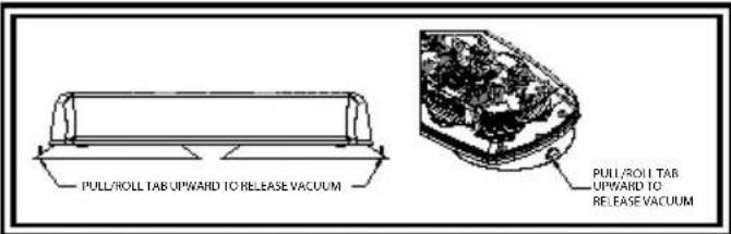
Figure 1

WARNING!
Failure to follow these instructions can result in fire or injury from excessive heat build up.
Operator is responsible for ensuring auxiliary plug fits correctly into auxiliary power plug outlet used.
For proper operation, verify auxiliary power outlet circuit is rated to supply a minimum of 10 amps. (See specifications section for rated current in amperes).
Do not exceed the current rating for the auxiliary power outlet recommended by vehicle manufacturer.
Keep auxiliary plug and outlet clean and free of debris.
Do not use the auxiliary plug when wet.
Insert auxiliary plug fully into the outlet for proper connection.
Grasp auxiliary plug, NOT cord, to remove from outlet.
Remove auxiliary plug completely from outlet when light is not in use.
Important! Disable power before wiring up the Minibar.
Vacuum Mount Installation for 5500 Series:
- Remove round black stickers for vacuum placement
- Remove lens screws, then remove lens.
- Unclip and remove wire harness
- Position vacuum magnets, place, and tighten screws.
- Insert pinned end of cable through the wire harness hole from the bottom of the base. Pull at least 6 inches of slack.
- Turn pins crimp side up, and insert pins into connector as shown in Figure 3.
- Place zip-tie 1.0" from base of the connectors shown in Figure 4. Zip-tie must not slide on cord.
- Trim excess zip-tie.
- Clip connector to the PCA board and pull slack until zip-tie touches base.
- Install lens, reverse of removal.
- Slide o-ring onto screw until it reaches head, before placing into lens. If o-rings are damaged, replace with new ones.
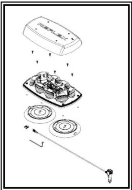
Figure 2
Note: Operating the Minibar without the lens installed on this product will result in damage that will not be covered under warranty.
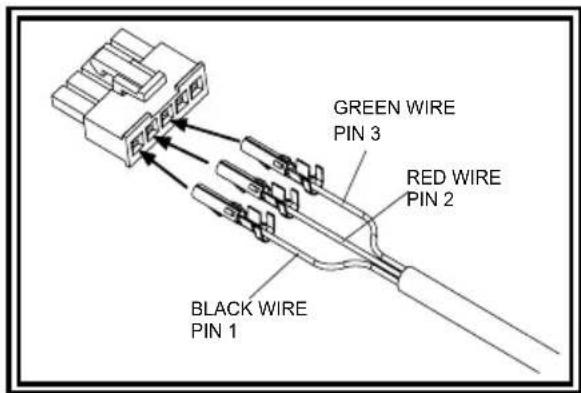
Figure 3
Magnet Mount Installation for 5500 Series:
- Refer to the appropriate Vacuum Mount Installation for the 5500 series, steps 2 through 9, and the corresponding Figures for wiring instructions for the cord.
- Place hex nut into the hex shaped retaining cavity on the inside of the mini-bar base.
- Place an internal star washer onto the enclosed M5 x 20 hex bolt and insert the hex bolt through the hole in the cup magnet as shown. Hold the magnet/bolt assembly with the bolt extended through the magnet as far as possible and feed the hex nut and the shank of the bolt through one of the openings at the 4 corners of the underside of the minibar base. Maintain tension on the bolt/nut by holding onto the cup magnet while tightening the assembly. Repeat this process for all four corners. See Figure 5.
- Place the adhesive magnet covers over the magnets.
- Replace the lens.
NOTE: Operating the vehicle without the outer lens installed on the product may result in damage that will NOT be covered under warranty.
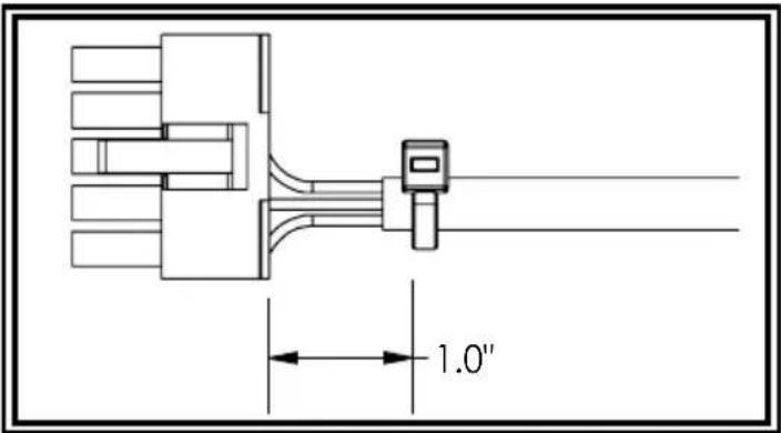
Figure 4
Note: The Magnet Mount is not recommended for use on a moving vehicle, nor is it intended as a permanent mount for the light. Long duration usage of the magnet in the presence of moisture will cause the steel to rust.
Wiring:
The wiring for the permanent mount minibar is as shown in Figure 6. All wiring should be a minimum of 18AWG. The positive line must have a 5 amp fuse, as shown. A switch may be used to control the on/off function.
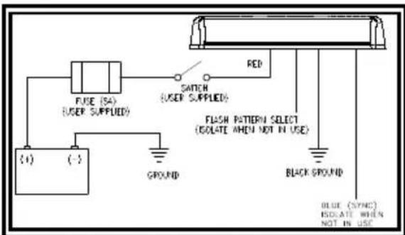
Figure 6
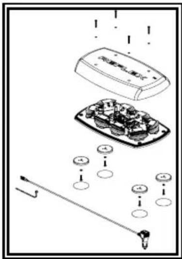
Figure 5
Flash Mode Selection:
Flash patterns can be selected on permanent mount minibars by touching the yellow wire to the red power wire for less than a second. Contacting the yellow and red wires for longer than a second toggles to the preceding flash pattern. The VM models have flash pattern select via a momentary switch on the cigarette plug.
Flash Pattern Syncing:
The 5585 permanent mount models sync with other compatible ECCO products via the blue wire:
- Determine the desired style of flash pattern for each unit and set each unit individually (without the BLUE wires connected together) to avoid confusion. It is also strongly recommended that the same style of flash pattern be used on all units to produce the most effective warning pattern. (NOTE: Phases A and B for each style of flash pattern in the table denote the relative timing between units connected in a synchronizing installation. To operate simultaneously, each unit must be set to the same phase (A + A or B + B); to operate alternately, units must be set to have the opposite phase (A + B or B + A)).
- Connect the BLUE (SYNC) wires together and check that the units are flashing in a synchronized manner as expected. If a pattern on one module appears to be wrong, the YELLOW (PATTERN SET) wire can be used to cycle forward or backward on that individual unit until the correct pattern is selected. Note: This will only change the pattern in the one unit and will not affect the other units connected to the BLUE (SYNC) wire.
- If the blue wire is unused, leave unconnected and insulated.
| Flash Pattern Chart, Tabla de Patrones de Intermitencia, Flash Graphique de Motif | ||||||||||||||||
| Sequence Description FPM Phase | SAE JS45 CA T13 | |||||||||||||||
| 5580A 55 | 80CA 55K5A | 587A 55K5C | A 55K5CH | 5585CC 55 | 85CR 55K5A | 5585CA 55 | S7CA 55K5C | B 5585CR | ||||||||
| 1 | Quad (Default) | 75 | A | CLASS 2 | CLASS 2 | CLASS 1 | CLASS 1 | CLASS 1 | CLASS 1 | CLASS 1 | CLASS 1 | CLASS E | CLASS E | CLASS E | CLASS E | CLASS E |
| 2 | Quad | 75 | B | - | - | CLASS 1 | CLASS 1 | CLASS 1 | CLASS 1 | CLASS 1 | CLASS 1 | CLASS E | CLASS E | CLASS E | CLASS E | CLASS E |
| 3 | Double | 75 | A | CLASS 2 | CLASS 2 | CLASS 1 | CLASS 1 | CLASS 1 | CLASS 1 | CLASS 1 | CLASS 1 | CLASS E | CLASS E | CLASS E | CLASS E | CLASS E |
| 4 | Double | 75 | B | - | - | CLASS 1 | CLASS 1 | CLASS 1 | CLASS 1 | CLASS 1 | CLASS 1 | CLASS E | CLASS E | CLASS E | CLASS E | CLASS E |
| 5 | Fast Double | 130 | A | CLASS 2 | CLASS 2 | - | - | - | - | - | - | - | - | - | - | - |
| 6 | Fast Double | 130 | B | - | - | - | - | - | - | - | - | - | - | - | - | - |
| 7 | Slow Quad | 65 | A | CLASS 2 | CLASS 2 | CLASS 1 | CLASS 1 | CLASS 1 | CLASS 1 | CLASS 1 | CLASS 1 | CLASS E | CLASS E | CLASS E | CLASS E | CLASS E |
| 8 | Slow Quad | 65 | B | - | - | CLASS 1 | CLASS 1 | CLASS 1 | CLASS 1 | CLASS 1 | CLASS 1 | CLASS E | CLASS E | CLASS E | CLASS E | CLASS E |
| 9 | Slow Double | 65 | A | CLASS 2 | CLASS 2 | CLASS 1 | CLASS 1 | CLASS 1 | CLASS 1 | CLASS 1 | CLASS 1 | CLASS E | CLASS E | CLASS E | CLASS E | CLASS E |
| 10 | Slow Double | 65 | B | - | - | CLASS 1 | CLASS 1 | CLASS 1 | CLASS 1 | CLASS 1 | CLASS 1 | CLASS E | CLASS E | CLASS E | CLASS E | CLASS E |
| 11 | Quint-hold | 75 | A | CLASS 2 | CLASS 2 | CLASS 1 | CLASS 1 | CLASS 1 | CLASS 1 | CLASS 1 | CLASS 1 | CLASS E | CLASS E | CLASS E | CLASS E | CLASS E |
| 12 | Quint-hold | 75 | B | - | - | CLASS 1 | CLASS 1 | CLASS 1 | CLASS 1 | CLASS 1 | CLASS 1 | CLASS E | CLASS E | CLASS E | CLASS E | CLASS E |
| 13 | Burst | 75 | A | CLASS 2 | CLASS 2 | CLASS 1 | CLASS 1 | CLASS 1 | CLASS 1 | CLASS 1 | CLASS 1 | - | - | - | - | - |
| 14 | Burst | 75 | B | - | - | CLASS 1 | CLASS 1 | CLASS 1 | CLASS 1 | CLASS 1 | CLASS 1 | - | - | - | - | - |
| 15 | Quad, Alternate Side-to-Side | 150 | CLASS 2 | CLASS 2 | CLASS 1 | CLASS 1 | CLASS 1 | CLASS 1 | CLASS 1 | CLASS 1 | - | - | - | - | - | |
| 16 | Quad, Diagonal Alternate | 150 | - | - | - | - | - | - | - | - | - | - | - | - | - | |
| 17 | Double, Alternate Side-to-Side | 150 | CLASS 2 | CLASS 2 | CLASS 1 | CLASS 1 | CLASS 1 | CLASS 1 | CLASS 1 | CLASS 1 | - | - | - | - | - | |
| 18 | Double, Diagonal Alternate | 150 | - | - | - | - | - | - | - | - | - | - | - | - | - | |
| 19 | Quint-hold, Alternate Side-to-Side | 150 | CLASS 2 | CLASS 2 | CLASS 1 | CLASS 1 | CLASS 1 | CLASS 1 | CLASS 1 | CLASS 1 | - | - | - | - | - | |
| 20 | Quint-hold, Diagonal Alternate | 150 | - | - | - | - | - | - | - | - | - | - | - | - | - | |
| 21 | Fast Rotate | 120 | CLASS 2 | CLASS 2 | CLASS 1 | CLASS 1 | CLASS 1 | CLASS 1 | CLASS 1 | CLASS 1 | - | - | - | - | - | |
| 22 | Rotate/Quad | 150/75 | - | - | - | - | - | - | - | - | - | - | - | - | - | |
| 23 | Wave Rotate | 70 | - | - | - | - | - | - | - | - | - | - | - | - | - | |
| 24 | Random | - | - | - | - | - | - | - | - | - | - | - | - | - | ||
| 25 | Steady | - | - | - | - | - | - | - | - | - | - | - | - | - | ||
Manufacturer Limited Warranty and Limitation of Liability:
Manufacturer warrants that on the date of purchase, this product will conform to Manufacturer's specifications for this product (which are available from the Manufacturer upon request). This Limited Warranty extends for thirty-six (36) months from the date of purchase.
DAMAGE TO PARTS OR PRODUCTS RESULTING FROM TAMPERING, ACCIDENT, ABUSE, MISUSE, NEGLIGENCE, UNAPPROVED MODIFICATIONS, FIRE OR OTHER HAZARD; IMPROPER INSTALLATION OR OPERATION; OR NOT BEING MAINTAINED IN ACCORDANCE WITH THE MAINTENANCE PROCEDURES SET FORTH IN MANUFACTURER'S INSTALLATION AND OPERATING INSTRUCTIONS VOIDS THIS LIMITED WARRANTY.
Exclusion of Other Warranties:
MANUFACTURER MAKES NO OTHER WARRANTIES, EXPRESSED OR IMPLIED. THE IMPLIED WARRANTIES FOR MERCHANTABILITY, QUALITY OR FITNESS FOR A PARTICULAR PURPOSE, OR ARISING FROM A COURSE OF DEALING, USAGE OR TRADE PRACTICE ARE HEREBY EXCLUDED AND SHALL NOT APPLY TO THE PRODUCT AND ARE HEREBY DISCLAIMED, EXCEPT TO THE EXTENT PROHIBITED BY APPLICABLE LAW. ORAL STATEMENTS OR REPRESENTATIONS ABOUT THE PRODUCT DO NOT CONSTITUTE WARRANTIES.
Remedies and Limitation of Liability:
MANUFACTURER'S SOLE LIABILITY AND BUYER'S EXCLUSIVE REMEDY IN CONTRACT, TORT (INCLUDING NEGLIGENCE), OR UNDER ANY OTHER THEORY AGAINST MANUFACTURER REGARDING THE PRODUCT AND ITS USE SHALL BE, AT MANUFACTURER'S DISCRETION, THE REPLACEMENT OR REPAIR OF THE PRODUCT, OR THE REFUND OF THE PURCHASE PRICE PAID BY BUYER FOR NON-CONFORMING PRODUCT. IN NO EVENT SHALL MANUFACTURER'S LIABILITY ARISING OUT OF THIS LIMITED WARRANTY OR ANY OTHER CLAIM RELATED TO THE MANUFACTURER'S PRODUCTS EXCEED THE AMOUNT PAID FOR THE PRODUCT BY BUYER AT THE TIME OF THE ORIGINAL PURCHASE. IN NO EVENT SHALL MANUFACTURER BE LIABLE FOR LOST PROFITS, THE COST OF SUBSTITUTE EQUIPMENT OR LABOR, PROPERTY DAMAGE, OR OTHER SPECIAL, CONSEQUENTIAL, OR INCIDENTAL DAMAGES BASED UPON ANY CLAIM FOR BREACH OF CONTRACT, IMPROPER INSTALLATION, NEGLIGENCE, OR OTHER CLAIM, EVEN IF MANUFACTURER OR A MANUFACTURER'S REPRESENTATIVE HAS BEEN ADVISED OF THE POSSIBILITY OF SUCH DAMAGES. MANUFACTURER SHALL HAVE NO FURTHER OBLIGATION OR LIABILITY WITH RESPECT TO THE PRODUCT OR ITS SALE, OPERATION AND USE, AND MANUFACTURER NEITHER ASSUMES NOR AUTHORIZES THE ASSUMPTION OF ANY OTHER OBLIGATION OR LIABILITY IN CONNECTION WITH SUCH PRODUCT.
This Limited Warranty defines specific legal rights. You may have other legal rights which vary from jurisdiction to jurisdiction. Some jurisdictions do not allow the exclusion or limitation of incidental or consequential damages.

ECCO®
833 West Diamond St
Boise, Idaho 83705
Customer Service
USA 800-635-5900
UK +44 (0)113 237 5340
AUS +61 (0)3 63322444
www.eccogroup.com
natural_image
Product image of a transparent electronic device with a brown case and a logo reading 'REFLEX' (no readable text or symbols on the device itself)
¡ADVERTENCIA!
Figura 5
Cableado:
natural_image
Product image of a REFLEX brand light fixture with transparent casing and internal components (no visible text or symbols on main body)
AVERTISSEMENT!
Figure 5