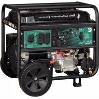
Onan P9500df - Generator Cummins - Free user manual and instructions
Find the device manual for free Onan P9500df Cummins in PDF.


| Product Type | Portable dual-fuel generator |
| Brand | Cummins |
| Model | Onan P9500df |
| Continuous power (gasoline) | 7500 W |
| Peak power (gasoline) | 9500 W |
| Continuous power (propane) | 6750 W |
| Peak power (propane) | 8550 W |
| Rated voltage | 120/240 V |
| Frequency | 60 Hz |
| Phase | Single phase |
| Fuel type | Gasoline (87-93 octane, max 10% ethanol) or propane/LPG |
| Tank capacity | 6.6 gallons (25 L) |
| Engine | 457 cc, 4-stroke |
| Start type | Recoil, electric and remote |
| Engine oil | SAE 10W-30, capacity 1.1 L |
| Spark plug | A064D660 (F7TC), gap 0.60-0.80 mm |
| Outlets | 2x GFCI NEMA 5-20R 120V 20A, 1x NEMA 14-30R 120/240V 30A, 2x USB 5V 2.1A |
| Circuit breakers | Main circuit breaker 40A, individual circuit breakers 20A |
| Grounding system | Neutral bonded to frame (disconnectable) |
| Voltage regulator | Digital |
| Alternator type | Brushed |
| Max ambient temperature | 40 °C (104 °F) |
| Certifications | EPA |
| Included accessories | Oil, funnel, battery charger, spark plug wrench, propane hose/regulator, remote control, wheel/foot kit |
| Break-in period | 50% max load for first 5 hours |
| Warranty | See terms on cummins.com |
Frequently Asked Questions - Onan P9500df Cummins
User questions about Onan P9500df Cummins
0 question about this device. Answer the ones you know or ask your own.
Ask a new question about this device
Download the instructions for your Generator in PDF format for free! Find your manual Onan P9500df - Cummins and take your electronic device back in hand. On this page are published all the documents necessary for the use of your device. Onan P9500df by Cummins.
USER MANUAL Onan P9500df Cummins
Onan P9500df Dual Fuel Portable Generator
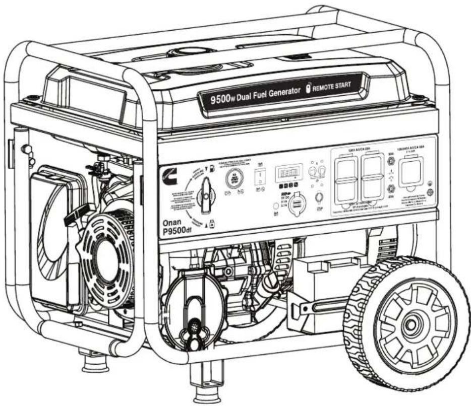
TABLE OF CONTENTS
INTRODUCTION
DISCLAIMERS....2
ALL RIGHTS RESERVED....2
SPECIFICATIONS....3
SAFETY
SAFETY DEFINITIONS....4
SAFETY SYMBOLS....4
SAFETY INSTRUCTIONS....5
SAFETY LABELS....8
COMPONENTS
GENERATOR COMPONENTS....9
CONTROL PANEL COMPONENTS....10
ASSEMBLY
CARTON CONTENTS 11
INSTALL FEET AND WHEELS....11
INITIAL OIL FILL....12
FUEL....12
CONNECT AN LPG/PROPANE TANK....13
CONNECT THE BATTERY....14
OPERATION
GENERATOR LOCATION....15
GROUNDING....15
HIGH ALTITUDE OPERATION....16
REMOTE START....16
FUEL SELECTOR SWITCH ....17
BREAK-IN PERIOD 17
BEFORE STARTING THE GENERATOR....17
STARTING THE ENGINE: GASOLINE....17
STARTING THE ENGINE: PROPANE....18
SWITCHING FUEL SOURCES....18
STOPPING THE ENGINE....19
INTRODUCTION
⚠ WARNING: Operating, servicing, and maintaining this equipment can expose you to chemicals including engine exhaust, carbon monoxide, phthalates, and lead, which are known to the State of California to cause cancer and birth defects or other reproductive harm. To minimize exposure, avoid breathing exhaust, and wear gloves or wash your hands frequently when servicing this equipment. For more information go to www.P65warnings.ca.gov.
DISCLAIMERS
All information, illustrations, and specifications in this manual were in effect at the time of publishing. The illustrations used in this manual are intended as representative reference views only. We reserve the right to make any specification or design change without notice.
FREQUENCY OF USE 19
AC CIRCUIT BREAKERS....19
POWER MANAGEMENT....20
EXTENSION CORDS 20
TRANSPORTING....21
MAINTENANCE REMINDERS ....21
MAINTENANCE
MAINTENANCE SCHEDULE 22
MAINTENANCE REPLACEMENT PARTS....22
AIR FILTER MAINTENANCE....22
ENGINE OIL CHANGE 23
SPARK PLUG MAINTENANCE....24
SPARK ARRESTOR SERVICE....24
FUEL FILTER....24
BATTERY MAINTENANCE....25
BATTERY REPLACEMENT....25
STORAGE 25
VALVE CLEARANCE....26
HIGH ALTITUDE KIT
HIGH ALTITUDE KIT ....27
TROUBLESHOOTING
TROUBLESHOOTING....31
EXPLODED VIEWS AND PARTS LISTS
ENGINE EXPLODED VIEW ....33
ENGINE PARTS LIST ....34
GENERATOR EXPLODED VIEW 35
GENERATOR PARTS LIST ....36
SCHEMATICS
SCHEMATICS....37
ESPAÑOL....36
FRANÇAIS......65
ALL RIGHTS RESERVED
All rights reserved. No reproduction allowed in any form without written permission from without the written permission of Cummins Inc.
DANGER

Read this manual before using or performing maintenance on this product. Failure to follow the instructions and safety precautions in this manual can result in serious injury or death.
SAVE THESE INSTRUCTIONS
SPECIFICATIONS
| Specifications | |
| Running Watts: | 7500 Gas / 6750 LPG |
| Peak Watts: | 9500 Gas / 8550 LPG |
| Rated Voltage: | 120/240V |
| Rated frequency: | 60 Hz @ 3600 RPM |
| Phase: | Single phase |
| Total Harmonic Distortion: | ≤ 23% |
| Engine Displacement: | 420 cc |
| Starting Type: | Recoil, Electric Start, Remote |
| Fuel Capacity: | 6.6 Gallons (25 Liters) |
| Fuel Type: | 87–93 octane* |
| Oil Capacity: | 1.16 US Quart (1.1 Liter) |
| Oil Type: | SAE 10W-30 |
| Spark Plug: | A064D660 (F7TC) |
| Spark Plug Gap: | 0.024 – 0.032 in.(0.60 – 0.80 mm) |
| Valve Intake Clearance: | 0.0031 – 0.0047 in.(0.08 – 0.12 mm) |
| Valve Exhaust Clearance: | 0.0051 – 0.0067 in.(0.13 – 0.17 mm) |
| AC Grounding System: | Bonded to frame |
| Voltage Regulator: | AVR |
| Alternator Type: | Brushed |
| Maximum Ambient Temperature: | 104°F (40°C) |
| Certifications: | EPA |
*Ethanol content of 10% or less. DO NOT use E15 or E85.
NOTICE
This product is designed and rated for continuous operation at ambient temperatures up to 104^ F ( 40^ C). If needed, this product can be operated at temperatures ranging from 5^ F ( 15^ C)– 122^ F ( 50^ C) for short periods. If the product is exposed to temperatures outside of this range during storage, it should be brought back within this range before operation. This product must ALWAYS be operated outdoors in a well-ventilated area and far away from doors, windows, and other vents.
Maximum wattage and current are subject to and limited by such factors as fuel BTU content, ambient temperature, altitude, engine conditions, etc. Maximum power decreases about 3.5% for each 1,000 feet above sea level, and will also decrease about 1% for each 10°F (6°C) above 60°F (16°C) ambient temperature.
PRODUCT REGISTRATION
To ensure trouble-free warranty coverage, it is important you register your Cummins generator.
You can register your product online at: www.cummins.com/support/product-registration
For Your Records
Date of Purchase: ____
Model Number: ____
Serial Number:
Place of Purchase: ____
IMPORTANT: Keep your purchase receipt for trouble-free warranty coverage.
To register your inverter you will need to locate the following information:
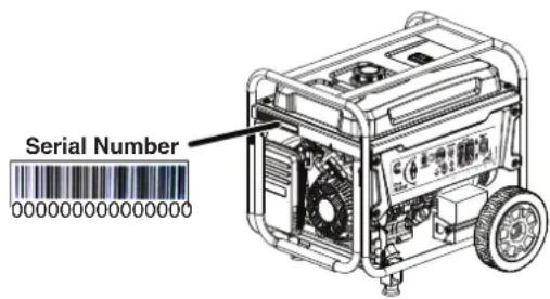
For Your Records
Date of Purchase: ____
Model Number:
Serial Number:
Place of Purchase: ____
IMPORTANT: Keep your purchase receipt for trouble-free warranty coverage.

1-800-CUMMINS
(1-800-286-6467)
SAFETY
SAFETY DEFINITIONS
The words DANGER, WARNING, CAUTION, and NOTICE are used throughout this manual to highlight important information. Make sure that the meanings of this safety information is known to all who operate, perform maintenance on, or are near the generator.

This safety alert symbol appears with most safety statements. It means attention, become alert, your safety is involved! Please read and abide by the message that follows the safety alerts symbol.
DANGER
Indicates a hazardous situation which, if not avoided, will result in death or serious injury.
WARNING
Indicates a hazardous situation which, if not avoided, could result in death or serious injury.
CAUTION
Indicates a hazardous situation which, if not avoided, could result in minor or moderate injury.
NOTICE
Indicates a situation which can cause damage to the generator, personal property, and/or the environment, or cause the equipment to operate improperly.
Note: Indicates a procedure, practice or condition that should be followed for the generator to function in the manner intended.
SAFETY SYMBOLS
Follow all safety information contained in this manual and on the generator.
| Symbol Description | |
 | Safety Alert Symbol |
 | Electrocution Hazard |
 | Asphyxiation Hazard |
 | Burn Hazard.DO NOT touch hot surfaces. |
 | Electrical Shock Hazard |
 | Fire Hazard |
 | Maintain Safe Distance |
 | Lifting Hazard |
 | Read Manufacturer's Instructions |
 | DO NOT Operate in Wet Conditions |
⚠️ DANGER
Using a generator indoors CAN KILL YOU IN MINUTES. Generator exhaust contains carbon monoxide. This is a poison you cannot see or smell.

NEVER use inside a home or garage, EVEN IF doors and windows are open.
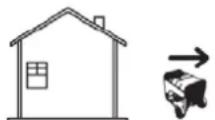
Only use OUTSIDE and far away from windows, doors, and vents.
SAFETY INSTRUCTIONS
CORRECT USE
Example location to reduce risk of carbon monoxide poisoning ONLY use outside and downwind, far away from windows, doors and vents. Direct exhaust away from occupied spaces
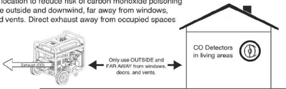

flowchart
graph TD
    A["Exhaust"] --> B["Living Area"]
    B --> C["Basement Crawlspace"]
    C --> D["Entryway Porch Mud Room"]
    D --> E["Garage"]
    style A fill:#f9f,stroke:#333
    style B fill:#ccf,stroke:#333
    style C fill:#cfc,stroke:#333
    style D fill:#fcc,stroke:#333
    style E fill:#cff,stroke:#333
INCORRECT USE
Do not operate in any of the following locations:
Near any door, window, or vent
• Garage
- Basement
- Crawl Space
• Living Area
- Attic
- Entry Way
- Porch
- Mudroom
NOTICE
Install battery-powered carbon monoxide detectors or plug-in carbon monoxide detectors with battery back-up in living areas.
DANGER
Fire and electrocution hazard. DO NOT connect to a building's electrical system unless the generator and transfer switch have been properly installed and the electrical output has been verified by a qualified electrician. The connection must isolate the generator power from utility power and must comply with all applicable laws and electrical codes.
DANGER
Electrocution hazard. NEVER use the generator in a location that is wet or damp. NEVER expose the generator to rain, snow, water spray, or standing water while in use. Protect the generator from all hazardous weather conditions. Moisture or ice can cause a short circuit or other malfunction in the electrical circuit.
GENERAL SAFETY PRECAUTIONS
- NEVER use the generator to power medical support equipment.
- DO NOT operate the generator when you are tired or under the influence of drugs, alcohol, or medication.
- DO NOT use generator with electrical cords which are worn, frayed, bare, or otherwise damaged.
- All electrical tools and appliances operated from this generator must be properly grounded by use of a third wire or be double-insulated.
- When this generator is used to supply a building wiring system the generator must be installed by a qualified electrician and connected to a transfer switch as a separately derived system in accordance with NFPA 70, National Electrical Code.
- If you begin to feel sick, dizzy, or weak while using the generator, move to fresh air IMMEDIATELY. See a doctor, as you can have carbon monoxide poisoning.
- Only use OUTSIDE and far away from windows, doors, and vents as recommended by the US Department of Health and Human Services Centers for Disease Control and Prevention. Your specific home and/or wind conditions may require additional distance.
- While operating and storing, keep at least five feet of clearance on all sides of the generator, including overhead. Allow the generator to cool a minimum of 30 minutes before storage. Heat created by the muffler and exhaust gases could be hot enough to cause serious burns and/or ignite combustible objects.
- DO NOT touch the muffler or engine. They are very HOT and will cause severe burns. DO NOT put body parts or any flammable or combustible materials in the direct path of the exhaust.
- ALWAYS remove any tools or other service equipment used during maintenance away from the generator before operating.
- Avoid skin contact with engine oil or gasoline. Wear protective clothing and equipment. Wash all exposed skin with soap and water.
- Use hearing protection when near the generator during operation.
FUEL SAFETY
- Store fuel in a container approved for gasoline.
- DO NOT smoke when filling the generator with gasoline.
- DO NOT allow the generator's gas tank to overflow when filling.
- Shut down the engine and allow it to cool for two minutes before adding gasoline or oil to the generator.
- NEVER remove the fuel cap when the generator is running. Shut off the engine and allow the unit to cool at least two minutes. Remove the fuel cap slowly to release pressure, keep fuel from escaping around the cap, and to avoid the heat from the muffler igniting fuel vapors. Tighten the fuel cap securely after refueling.
- Wipe spilled fuel from the unit.
• NEVER attempt to burn off spilled fuel. - NEVER overfill the fuel tank. Leave room for fuel to expand. Overfilling the fuel tank can result in a sudden overflow of gasoline and result in spilled gasoline coming in contact with HOT surfaces.
- Spilled fuel can ignite. If fuel is spilled on the generator, wipe up any spills immediately. Dispose of rag properly. Allow area of spilled fuel to dry before operating the generator.
- Wear eye protection while refueling.
- NEVER use gasoline as a cleaning agent.
- Store any containers containing gasoline or LPG/propane in a well-ventilated area, away from any combustibles or source of ignition.
Fire and explosion hazard. Gasoline and LPG/propane are highly explosive and flammable and can cause severe burns or death.
- In case of a gas fire, DO NOT attempt to extinguish the flame if the fuel tank valve is in the ON position. Introducing an extinguisher to a generator with an open fuel valve could create an explosion hazard.
- Gas has a distinctive odor, this will help detect potential leaks quickly.
• Gas vapors can cause a fire if ignited. - Gasoline is a skin irritant and needs to be cleaned up immediately if it comes in contact with the skin.
LIQUID PETROLEUM GAS (LPG/PROPANE)
WARNING
Fire and explosion hazard. NEVER use a gas container, LPG/propane connector hose, LPG/propane tank or any other fuel item that appears to be damaged.
CAUTION
Fire and explosion hazard. Only use approved LPG/propane tanks with an Overfilling Prevention Device (OPD) valve. ALWAYS keep the tank in a vertical position with the valve on top and placed at ground level on a flat surface. DO NOT allow tanks to be near any heat source. When transporting and storing, turn the propane tank valve to the fully closed position and disconnect the tank. Make sure to ALWAYS cover the generator inlet and tank outlet with protective plastic caps.
• LPG/Propane is highly flammable and explosive.
- Flammable gas under pressure can cause a fire or explosion if ignited.
- LPG/Propane can settle in low places because it is heavier than air.
- LPG/Propane has a distinctive odor added to help detect potential leaks.
- ALWAYS keep a LPG/Propane tank in an upright position.
- When exchanging LPG/propane tanks, be sure the tank valve is the same type.
- In case of a LPG/propane fire, DO NOT attempt to extinguish unless the fuel supply can be shut off safely.
- LPG/propane will burn the skin. Prevent skin contact at all times.
- Keep the propane tank away from the generator exhaust.
- A step-down regulator is required when using LPG/propane tanks over 100 gallons. The pressure as measured at the regulator mounted to the generator must be 7" to 14" of water column.
- Large (500–1000 gallon) LPG/propane tanks will require a certified plumber to install the fuel line to the generator and the loose regulator is not used (the regulator that is attached to the fuel tank). The pressure as measured at the regulator mounted to the generator must be 7" to 14" of water column. A certified plumber must ensure that the pressure is correct or install a step down regulator if needed.
WARNING
Fire and explosion hazard. If there is a strong smell of propane while operating the generator, fully close the LPG/propane tank valve immediately. Once the propane is off, use soapy water to check for leaks on the hose and connections on the tank valve and the generator. DO NOT smoke or light a cigarette or check for leaks using any open flame source such as a match or lighter. If a leak is found, contact a qualified technician to inspect and repair the LPG/propane system before using the generator.
When starting the generator:
• Make sure that the fuel cap, air filter, spark plug, fuel lines, and exhaust system are properly in place.
- If you spill any gasoline on the tank, allow it to fully evaporate before operating.
• Make sure the generator and LPG/propane tank are on a flat surface before operating.
- If there is a propane odor DO NOT start the unit because there may be a potential leak. NEVER place a LPG/propane tank near the engine exhaust.
When transporting or servicing the generator:
- Make sure the LPG/propane tank and LPG/propane hose are not attached to the generator.
- Disconnect the spark boot to prevent accidental starting.
When storing the generator:
- Store away from sparks, open flames, pilot lights, heat, and other sources of ignition.
- DO NOT store gas or a LPG/propane tank near furnaces, water heaters, or any other appliances that produce heat or have automatic ignitions.
SAFETY LABELS
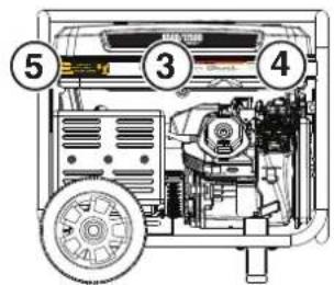
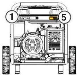
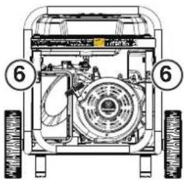


Model Modelo Modèle
Part No Numero de
AC Current Corriente
alterna Courant alternatif
Power (Rated) Power
Power (Peak) Poder (pipe)
Puissance (Pointe)
RPM TRIMIN
Frequency Escuela /
Influences
Insul Class Clase de
aislamiento Classe D'isol
Max Amb Temp Temperature
maxima Max temp
Fuel Combustible Carburant
As the owner's manual and fellow all safety procedures prior to operating the generator, Failure to follow these instructions may lead to overrun injury, property damage or death. Never add fuel to generator when the engine is hot or running, never add fuel to come in contact with running engine or hot generator parts. Always allow engine to cool down before adding fuel. Never touch hot surfaces, Generation pose risk of shock especially if operated in damp or wet conditions. Keep generator and stored fundsway from fire, sparks and cigarettes. Never correct to a building electrical system unless a transfer switch has been protected by a wired electricity.
▲ PELIGRO
TOXIC FUMES HAZARD. Running engines gives off carbon monoxide, an odourless poisonous gas that can cause nausea, fainting, or death. Do not start engine indoors or in an enclosed area, even if the windows and doors are open.
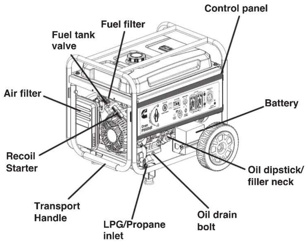
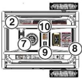
CONTROL PANEL COMPONENTS
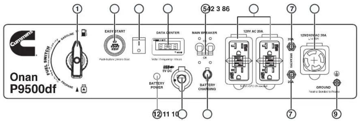
- Fuel Selector Switch: Used to select gas or propane operation.
- Push-Button START/STOP: Push once to automatically start the engine. Push again to stop the engine.
- Battery Switch: Turns battery ON and OFF. Must be ON before electric or remote start.
- Data Center: Toggle to show voltage, frequency, total hour meter, and run/maintenance timer.
- Main Circuit Breaker: The main circuit breaker controls total output of all outlets to protect the generator from overload or short circuit.
-
120 Volt AC, 20 Amp Duplex GFCI NEMA 5-20R Receptacles: Receptacles can supply a maximum of 20 Amps.
-
20 Amp AC Circuit Breakers: Circuit breakers limits the current that can be delivered through the NEMA 5-20R receptacles to 20 Amps.
- 120/240 Volt AC, 30 Amp NEMA 14-30R Twist-Lock Receptacle: Receptacle can supply a maximum of 30 Amps.
- Ground Terminal: The ground terminal is used to externally ground the generator.
- Battery Charging Port: Used to charge the battery with the included battery charger.
- USB Ports: Two-port 5V/2.1A USB outlet. Accepts Type A USB plugs.
- Battery Indicator: Indicates that power is ON. Light will remain illuminated while the unit is ON.
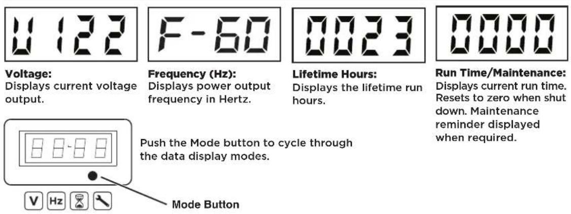
DATA CENTER
ASSEMBLY
CARTON CONTENTS
CAUTION
Weight hazard. ALWAYS have assistance when lifting the generator.
- Carefully open the carton.
- Remove and save the carton contents.
- Remove and discard the packing tray.
- Unfold the top of the plastic bag enclosing the generator.
- Carefully cut the vertical corners of the carton to access the generator.
- Recycle or dispose of the packaging materials properly.
CARTON CONTENTS
- User manual
- Quick Start Guide/Maintenance Schedule
• LPG/propane hose with regulator - Remote start key fob (attached to recoil starter)
• 1.16 Quart (1.1 Liter) bottle of SAE 10W-30 Oil - Battery charger
- Spark plug socket wrench
- Oil Funnel
- Assembly wrench
• Wheel and mounting foot components
Item Quantity
- Mounting foot 2
- Flange bolt, M8 4
- Wheel 2
- Axle pin 2
- Washer 2
- Cotter pin 2
If any parts are missing, contact our service team at 1-800-286-6467.
INSTALL FEET AND WHEELS
NOTICE
Assembling the generator will require lifting the unit on one side. Install the mounting feet and wheel before adding fuel or oil.
- Place generator on a flat surface.
- Tip the generator on a piece of cardboard or other soft material to protect the frame paint and prevent the generator from sliding.
- With the included wrench, install the mounting feet to the frame as shown.
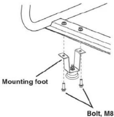
- Install the wheels as shown.
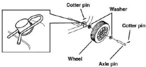
Note: The wheels are only intended for hand transport. The wheels are not suitable for towing the generator either on or off-road.
INITIAL OIL FILL
NOTICE
THIS GENERATOR HAS BEEN SHIPPED WITHOUT OIL. DO NOT attempt to crank or start engine before it has been properly serviced with recommended oil. Failure to add engine oil before starting will result in serious engine damage.
NOTICE
Use of 2-stroke/cycle oil or other unapproved oil types can cause severe engine damage that is not covered under warranty.
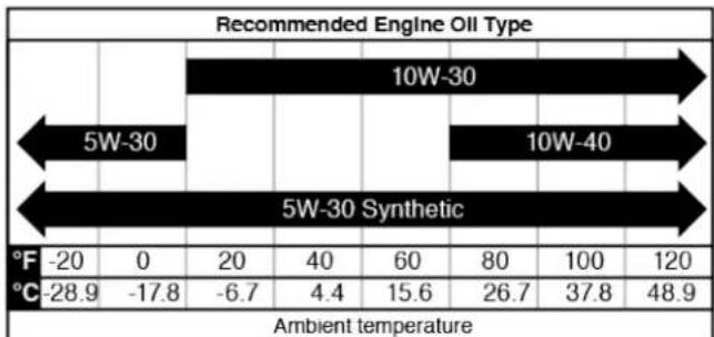
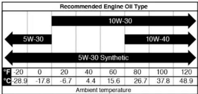
The included, recommended oil type for typical use is 10W-30 engine oil. If running the generator in extreme temperatures, refer to the following chart.
bar
Recommended Engine Oil Type | Category | 5W-30 (°F) | 5W-30 (°C) | 10W-30 (°F) | 10W-30 (°C) | 5W-30 Synthetic (°F) | 5W-30 Synthetic (°C) | |---|---|---|---|---|---|---| | Ambient temperature | -20 | -28.9 | 0 | -17.8 | 20 | -6.7 | | Ambient temperature | 40 | 4.4 | 60 | 15.6 | 80 | 26.7 | | Ambient temperature | 80 | 26.7 | 100 | 37.8 | 120 | 48.9 | The chart displays a single bar for the '5W-30' category in the top section and a single bar for the '5W-30 Synthetic' category in the bottom section. The values are estimated based on the numerical labels above each bar.- On a level surface, remove the oil dipstick.
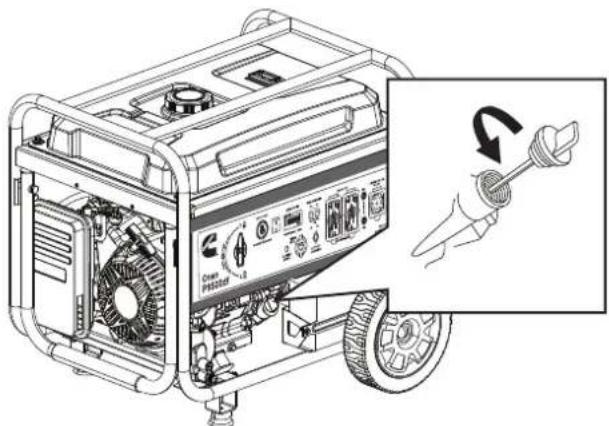
- Using the supplied funnel and oil, add oil into oil filler neck.
Note: As residual oil from the factory may remain in the engine, add the oil incrementally near the end of the bottle to prevent overfilling the engine. See Engine Oil Level Check in the Maintenance section.
- Replace the oil dipstick and hand-tighten.
FUEL
WARNING
Fire and explosion hazard. NEVER use a gasoline container, gasoline tank, propane connector hose, propane tanks, or any other fuel item that is broken, cut, torn or damaged.
DANGER
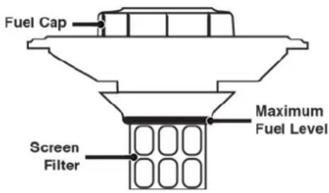
Fire and explosion hazard. DO NOT overfill fuel tank. Fill only to the red fill ring located in the in-tank fuel screen filter. Overfilling may cause fuel to spill onto engine causing a fire or explosion hazard.
⚠️ DANGER
Fire and explosion hazard. NEVER refuel the generator while the engine is running. ALWAYS turn the engine off and allow the generator to cool for two minutes before refueling.
NOTICE

DO NOT use E15 or E85 fuel in this product. Engine or equipment damage caused by stale fuel or the use of unapproved fuels (such as E15 or E85 ethanol blends) is not covered by warranty. Only use unleaded gasoline containing up to 10% ethanol.
FUEL REQUIREMENTS
- CLEAN, FRESH, unleaded gasoline, 87–93 octane.
- Up to 10% ethanol (gasohol) is acceptable (where available; non-ethanol fuel is recommended).
• DO NOT use E85 or E15.
• DO NOT use a gas oil mix.
• DO NOT modify the engine to run on alternate fuels.
• DO NOT fuel indoors.
• DO NOT create a spark or flame while fueling.
USING FUEL STABILIZER
Adding a fuel stabilizer (not included) extends the usable life of fuel and helps prevent deposits from forming that can clog the fuel system. Follow the manufacturer's instructions for use.
ALWAYS mix the correct amount of fuel stabilizer to gasoline in an approved gasoline container before fueling the generator. Run the generator for five minutes to allow the stabilizer to treat the entire fuel system.
FILLING THE FUEL TANK
- Turn the generator OFF and allow to cool for a minimum of two minutes before fueling.
- Place the generator on level ground in a well ventilated area.
- Clean area around fuel cap and remove the cap slowly.
NOTICE
Only fill the tank from an approved gasoline container. Make sure the gasoline container is internally clean and in good condition to prevent fuel system contamination.
- Slowly add the recommended fuel. DO NOT overfill. Fill only to the red maximum fill ring on the fuel screen filter visible in the filler neck.
- Install the fuel cap.
NOTICE
Fuel can damage paint and plastic. Use caution when filling the fuel tank. Damage caused by spilled fuel is not covered under warranty.
NOTICE
Clean the fuel screen filter of debris before and after each fueling. Remove the fuel screen filter by slightly compressing it while removing it from the fuel tank.
CONNECT AN LPG/PROPANE TANK
NOTICE
- The LPG/propane tank can be of any capacity but the tank must conform to the standard as listed in Fuel Safety section.
- Propane tanks that use liquid withdrawal system can not be used on these models.
- Verify the re-qualification date on the tank has not expired.
- DO NOT use included LPG/propane hose for any other appliances.
NOTICE
- All new tanks must be purged of air and moisture prior to filling. Used tanks that have not been plugged or kept closed must also be purged. The purging process should be done by a propane supplier (Tanks from an exchange supplier should have been purged and filled properly).
- ALWAYS position the tank so the connection between the valve and the gas inlet will not cause sharp bends or kinks in the hose.
WARNING
Explosion hazard. DO NOT start generator if you smell LPG. ALWAYS fully close the propane tank valve and disconnect the LPG/propane hose from the generator when not in use.
- Turn the generator OFF and place on a flat surface in a well ventilated area.
- Verify that the propane tank valve is in the fully closed position.
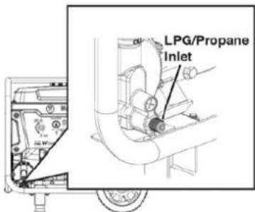
- Remove the cover on the generator propane inlet valve.
- Use your fingers to hand thread the LPG/propane hose (included) to the propane inlet on the generator.
IMPORTANT: DO NOT use thread seal tape or any other type of sealant to seal the LPG/propane hose connection.
- Tighten the LPG/propane hose connector to the generator with a 19 mm or adjustable wrench. DO NOT over-tighten.
Torque: 5-10 lb-ft.
-
Remove the safety plug or cap from the propane tank valve and attach the other end of the hose to the LPG/propane connector on the tank. Hand tighten.
-
Turn the propane tank valve to the fully open position. Check all connections for leaks by wetting the fittings with a solution of soap and water. Bubbles which appear or bubbles which grow indicate that a leak exists. If a leak exists at a fitting, turn the propane tank valve to the fully closed position and tighten the fitting. Open the propane tank valve and recheck the fitting with the soap and water solution. If the leak continues or if the leak is not at a fitting then DO NOT use the generator and contact customer service.
IMPORTANT: Keep the propane tank valve in the fully closed position unless in use.
CONNECT THE BATTERY
A quick-connect battery plug is pre-installed on the battery. Remove the cable tie securing the plugs then push firmly to connect them.
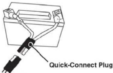
Note: The generator is equipped with a battery charging feature. Once the engine is running, a small charge will slowly recharge the battery.
OPERATION
GENERATOR LOCATION
Read and understand all safety information before starting the generator.
DANGER
Using a generator indoors CAN KILL YOU IN MINUTES. Generator exhaust contains carbon monoxide. This is a poison you cannot see or smell.

NEVER use inside a home or garage, EVEN IF doors and windows are open.
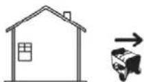
Only use OUTSIDE and far away from windows, doors, and vents.
NEVER operate the generator inside any building, including garages, basements, crawlspaces, sheds, enclosure, or compartment, including the generator compartment of a recreational vehicle.
DANGER
Electrocution hazard. NEVER use the generator in a location that is wet or damp. NEVER expose the generator to rain, snow, water spray, or standing water while in use. Protect the generator from all hazardous weather conditions. Moisture or ice can cause a short circuit or other malfunction in the electrical circuit. Using a generator or electrical appliance in wet conditions, such as rain or snow, or near a pool or sprinkler system, or when your hands are wet, could result in electrocution
WARNING
Fire hazard. Only operate the generator on a solid, level surface. Operating the generator on a surface with loose material such as sand or grass clippings can cause debris to be ingested by the generator that could block cooling vents or the air intake system. Allow the generator to cool for 30 minutes before transport or storage.
The generator should be on a flat, level surface at all times (Even while not in operation). The generator must have at least 5 ft. (1.5 m) of clearance from all combustible material.
DO NOT operate the generator in the back of a SUV, camper, trailer, truck bed (regular, flat, or otherwise), under stairs, next to walls or buildings, or in any other location that will not allow for adequate cooling of the generator and/or the muffler. DO NOT contain generators during operation.
DANGER
Asphyxiation hazard. Place the generator in a well-ventilated area. DO NOT place the generator near vents or intakes where exhaust fumes could be drawn into occupied or confined spaces. Carefully consider wind and air currents when positioning the generator.
GROUNDING
WARNING
Shock hazard. Failure to properly ground the generator can result in electric shock.
NOTICE
Only use grounded 3-prong extension cords, tools, and appliances, or double-insulated tools and appliances.
The generator neutral is bonded to the frame. There is a permanent conductor between the generator (stator wire) and the frame. If this generator will be used only with cord and plug equipment connected to the receptacles mounted on the generator, National Electric Code does not require that the unit be grounded. However, other methods of using the generator may require grounding to reduce the risk of shock or electrocution.
Before using the ground terminal, consult a qualified electrician, electrical inspector, or local agency having jurisdiction for local codes or ordinances that apply to the intended use of the generator.
DISCONNECTING THE BONDED NEUTRAL
Removing the bonded neutral disables the GFCI protection from the 5-20R receptacles. The bonded neutral should only be removed under specific circumstances. Consult a qualified electrician to determine if your situation requires disconnecting the bonded neutral.
- Remove the alternator cover.
- Remove the bonded jumper wire and reinstall the nut.
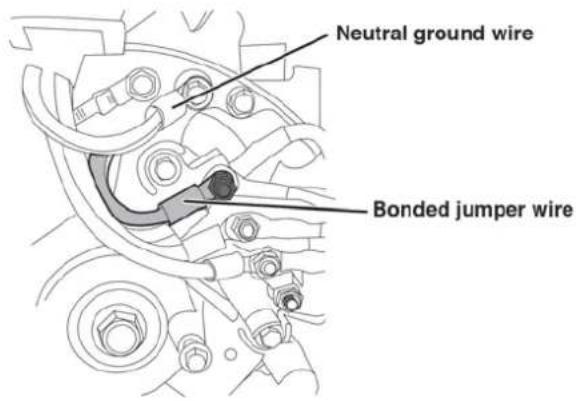
- Remove the nut securing the neutral ground wire and attach the bonded jumper wire. Reinstall the nut.

- Reinstall the alternator cover.
IMPORTANT: Apply a new "NEUTRAL UNBONDED" Label over the "NEUTRAL BONDED TO FRAME" label on the front of the control panel.
Engine power is reduced the higher you operate above sea level. Output will be reduced approximately 3.5% for every 1000 feet of increased altitude from sea level.
High altitude adjustment is required for operation at altitudes over 2,000 ft. (762 m). Operation without this adjustment will cause decreased performance, increased fuel consumption, and increased emissions.
NOTICE
Do not operate the generator at altitudes below 2,000 ft. (762 m) with the high altitude kit installed. Engine damage may occur.
High Altitude Carburetor Kit Part# A058V084
High Altitude DF Regulator: Part# A065P007
Note: You must purchase both the Dual Fuel Regulator and Carburetor Kit for proper high altitude operation.
REMOTE START
WARNING
Verify that the area around the generator is clear before remote starting the generator.
The remote start key fob included with the generator should be attached to the recoil handle or control panel. If your unit was shipped without a key fob, contact Cummins customer service.
The generator can be started remotely from up to 99 feet (30 meter) using the remote start key fob.
Note: As the batteries in the remote start key fob drain, operational distance will decrease.
PAIRING THE REMOTE START
Remote replacement batteries: (2) CR2016
Remote replacement: A058M291
If the remote start key fob is replaced or needs re-paired to the generator, follow this procedure.
- Turn the generator battery switch to the ON position. The power indicator light will illuminate.
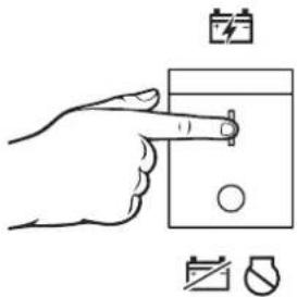
- Push and hold the red Pairing button on the side of the control panel until the START/STOP button illuminates.
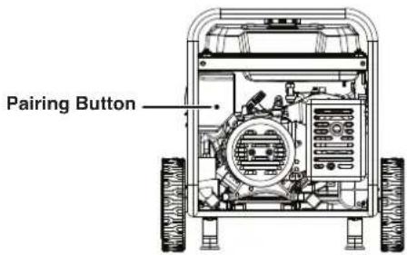
- Push and hold the STOP button on the key fob until the START/STOP button illumination turns OFF. Release the button. The START/STOP button will illuminate after the button is released.
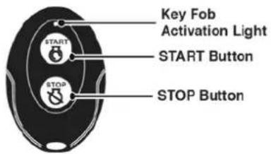
-
Push and hold the START button on the key fob until the START/STOP button illumination turns OFF. Release the button. The START/STOP button will illuminate after the button is released.
-
Push the Pairing button on the side of the control panel until the START/STOP button illumination turns OFF. Release the button.
-
Turn the generator battery switch to the OFF position. The remote is now paired.
FUEL SELECTOR SWITCH
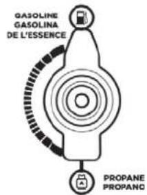
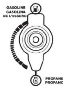
Position the fuel selector switch on the front control panel to the desired fuel choice.
Turn the fuel selector switch fully upward for gasoline operation.
Turn the fuel selector switch fully downward for propane operation.
BREAK-IN PERIOD
For proper break-in, DO NOT exceed 50% of the rated running watts (3750 watts) during the first five hours of operation.
Vary the load occasionally to allow stator windings to heat and cool and help seat the piston rings.
BEFORE STARTING THE GENERATOR
Verify that:
- The generator is placed in an safe, appropriate location.
• The generator is on a dry, flat, and level surface.
• The engine is filled with oil.
• All loads are disconnected.
⚠️ DANGER
Fire and explosion hazard. DO NOT move or tip the generator during operation.
STARTING THE ENGINE: GASOLINE
- Verify that fuel is in the gas tank.
- Turn the fuel selector switch on the control panel to gasoline operation.
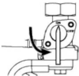
- Turn the fuel tank valve to the ON position.
- Push the battery switch to the ON position.
- Choose the starting method:
a. Remote Start: Push and hold the START button on the remote start key fob for one second.
b. Push-Button Start: Push and hold the engine START/STOP button for two seconds.
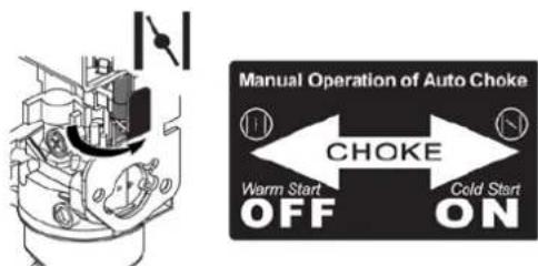
Note: During Push-Button or Remote Start the engine will automatically set the choke and begin the start sequence. If the engine fails to start, the generator will attempt to start the engine two more times. The choke must be turned ON manually if recoil starting.
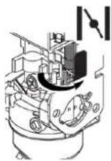
c. Recoil Start: Manually close the choke if the engine is cold. Firmly grasp and pull the recoil handle slowly until you feel increased resistance, then pull rapidly.
Cold start: Close the choke by moving it right toward the front handle of the generator.
STARTING THE ENGINE: PROPANE
DANGER
Fire and explosion hazard. ALWAYS turn the propane tank valve to the fully closed position if not running the generator on propane.
- Make sure the LPG/propane hose is correctly connected to the generator and propane tank.
- Turn the fuel selector switch to propane operation.
- Fully open the valve on the propane tank.
- Push the battery switch to the ON position.
- Choose the starting method:
a. Remote Start: Push and hold the START button on the remote start key fob for one second.
b. Push-Button Start: Push and hold the engine START/STOP button for two seconds.
Note: During Push-Button or Remote Start the engine will automatically set the choke and begin the start sequence. If the engine fails to start, the generator will attempt to start the engine two more times. The choke must be turned ON manually if recoil starting.
c. Recoil Start: Manually close the choke if the engine is cold. Firmly grasp and pull the recoil handle slowly until you feel increased resistance, then pull rapidly.
Cold start: Close the choke by moving it right toward the front handle of the generator.

SWITCHING FUEL SOURCES
DANGER
Fire and explosion hazard. DO NOT add gasoline to the fuel tank or connect the LPG/propane hose to the generator while the generator is in operation.
The fuel source can be switched while the engine is running if a propane tank is connected to the generator BEFORE operation.
GASOLINE TO PROPANE
IMPORTANT: Load capacity is reduced when running on propane. Make sure the generator can supply enough (running) and surge (starting) watts for the items you are powering before switching to propane.
- Fully open the valve on the propane tank.
- Turn the fuel selector switch to propane operation.
- Turn the fuel tank valve to the OFF position.
PROPANE TO GASOLINE
- Turn the fuel tank valve to the ON position.
- Turn the fuel selector switch to gasoline operation.
- Turn the propane tank valve to the fully closed position.
Note: When switching to propane operation the engine may run rough for a few seconds while it purges gasoline in the carburetor.
If the engine stops when switching fuel sources, disconnect all loads then restart the unit on the fuel source of choice.
STOPPING THE ENGINE
- Turn off and unplug all connected electrical loads.
IMPORTANT: NEVER start or stop the generator with electrical devices connected. - Let the generator run with no load for several minutes to stabilize internal temperatures of the engine.
- Push and hold the START/STOP button for one second or push STOP on the remote start key fob for one second.
Note: Alternately, if the generator is used infrequently, turn the fuel tank valve to the OFF position to limit the residual fuel remaining in the carburetor float bowl. The engine will stop when fuel in the carburetor and fuel line is exhausted. - Push the battery switch to the OFF position.
- If operating on LPG, turn the propane tank valve to the fully closed position.
FREQUENCY OF USE
If the generator will be used on an infrequent or intermittent basis (more than one month before next use), refer to the Battery Maintenance and Storage sections of this manual for information regarding battery charging and fuel deterioration.
AC CIRCUIT BREAKERS
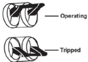
The circuit breakers will automatically switch OFF if there is a short circuit or a significant overload of the generator at each receptacle.
If an AC circuit breaker switches OFF automatically, check that the appliance is working correctly and it does not exceed the rated load capacity of the circuit before resetting the AC circuit breaker ON.
Receptacle Circuit Breakers
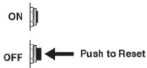
Main Circuit Breaker
GENERATOR CAPACITY
NOTICE
DO NOT overload the generator's capacity. Exceeding the generator's wattage/amperage capacity can damage the generator and/or electrical devices connected to it.
Make sure the generator can supply enough continuous (running) and surge (starting) watts for the items you will power at the same time.
The total power requirements (Volts x Amps = Watts) of all appliances connected must be considered. Appliance and power tool manufacturers usually list rating information near the model or serial number.
To determine power requirements:
- Select the items you will power at the same time.
- Total the continuous (running) watts of these items. This is the amount of power the generator must produce to keep the items running. See the wattage reference chart on the next page.
- Estimate how many surge (starting) watts you will need. Surge wattage is the short burst of power needed to start electric motor-driven tools or appliances such as a circular saw or refrigerator. Because not all motors start at the same time, total surge watts can be estimated by adding only the item(s) with the highest additional surge watts to the total rated watts from step 2.
Example:
| Tool or Appliance | Running Watts* | Starting Watts* |
| RV Air Conditioner (11,000 BTU) 1010 1600 | ||
| TV (Tube Type) 300 0 | ||
| RV Refrigerator 180 600 | ||
| Radio 200 0 | ||
| Light (75 Watts) 300 0 | ||
| Coffee Maker 600 0 | ||
| 2590 Total | 1600 | |
| Running Watts* | Highest Starting Watts* | |
| Total Running Watts 2590 | ||
| Highest Starting Watts + 1600 | ||
Total Starting Watts Needed 4190
*Wattages listed are approximate. Verify actual wattage.
POWER MANAGEMENT
To prolong the life of the generator and attached devices, use care when adding electrical loads to the generator. There should be nothing connected to the generator outlets before starting the engine. The correct and safe way to manage generator power is to sequentially add loads as follows:
- With nothing connected to the generator, start the engine as described in this manual.
- Plug in and turn on the first load, preferably the largest load you have.
- Permit the generator output to stabilize (engine runs smoothly and attached device operates properly).
- Plug in and turn on the next load.
- Again, permit the generator to stabilize.
- Repeat steps 4 and 5 for each additional load.
Wattage Reference
| Tool or Appliance | Estimated Running Watts* | Estimated Starting Watts* |
| Incandescent Lights(4 Quantity x 75 Watts) | 300 0 | |
| TV (Tube Type) 300 0 | ||
| Sump Pump (1/3 hp) 800 1300 | ||
| Refrigerator or Freezer 700 2200 | ||
| Well Pump (1/3 hp) 1000 2000 | ||
| Furnace (1/2 hp) 800 2350 | ||
| Radio 200 0 | ||
| Drill (3/8", 4 amps) 440 600 | ||
| Circular Saw(Heavy Duty, 7-1/4") | 1400 2300 | |
| Miter Saw (10") 1800 1800 | ||
| Table Saw (10") 2000 2000 |
*Wattages listed are approximate. Verify actual wattage.
EXTENSION CORDS
WARNING
Asphyxiation hazard. Extension cords running directly into the home increase the risk of carbon monoxide poisoning through any openings. If an extension cord running directly into your home is used to power indoor items, there is a risk of carbon monoxide poisoning to people inside the home. ALWAYS use battery-powered carbon monoxide detector (s) that meet current UL 2034 safety standards when running the generator. Regularly check the detector (s) battery.
WARNING
Asphyxiation hazard. When operating the generator with extension cords, make sure the generator is located in an open, outdoor area, far away from occupied spaces with exhaust pointed away.
WARNING
Fire and electrocution hazard. NEVER use worn or damaged extension cords. Damaged or overloaded extension cords could overheat, arc, and burn resulting in death or serious injury.
Before connecting an AC appliance or power cord to the generator:
- Use grounded 3-prong extension cords, tools, and appliances, or double-insulated tools and appliances.
- Make sure the tool or appliance is in good working order. Faulty appliances or power cords can create a potential for electric shock.
- Make sure the electrical rating of the tool or appliance does not exceed the rated power of the generator or the receptacle being used.
EXTENSION CORD SIZING
Only use grounded 3-prong extension cords marked for outdoor use that are rated for the electrical load.
| Total Amperage | Minimum Gauge, Outdoor Rated | |
| Up to 50 FT (15 M) | Up to 100 FT (30 M) | |
| Up to 10A |  |  |
| Up to 15A |  |  |
| Up to 20A |  |  |
| Up to 30A |  |  |
| Up to 35A |  |  |
TRANSPORTING
CAUTION
Weight hazard. ALWAYS have assistance when lifting the generator.
- Allow the generator to cool a minimum of 30 minutes before transporting.
- If operating on LPG, turn the propane tank valve to the fully closed position.
- Disconnect the LPG/propane hose from the generator and propane tank.
- Replace all protective covers on the generator control panel.
- Only use the generator's fixed frame to lift the unit or attach any load restraints such as ropes or tie-down straps. DO NOT attempt to lift or secure the generator by holding onto any of its other components.
- Keep the unit level during transport to minimize the possibility of fuel leakage or, if possible, drain the fuel or run the engine until the fuel tank is empty before transport.
- The generator wheels are only intended for hand transport. The wheels are not suitable for towing the generator either on or off-road.
- Use the extendable handle for one-person, hand transport. Only use the handle while the generator is OFF, stationary, and resting on a horizontal surface. DO NOT use the handle to lift the generator entirely off the ground, tow it, or up-end it.
CAUTION
Fire hazard. DO NOT up-end the generator or place it on its side. Fuel or oil can leak and damage to the generator may occur.
Maintenance reminder codes will be shown on the Data Display based on unit Lifetime Hours. The maintenance codes will be displayed until the unit is turned off. Refer to the Maintenance section for specific procedures.
Maintenance Code Required Maintenance
| P25 Change | engine oil |
| P50 Change | engine oil, clean air filter |
| P100 | Change engine oil, clean air filter, replace fuel filter |
MAINTENANCE
WARNING
Accidental start-up. Disconnect the spark plug boot from the spark plug and disconnect the battery quick-connect plugs when performing maintenance on the generator.
MAINTENANCE SCHEDULE
Regular maintenance will improve performance and extend the service life of the generator. Follow the hourly or calendar intervals, whichever occurs first. More frequent service is required when operating in adverse conditions as noted below.
Before Each Use
Check engine oil
After First 25 Hours or First Month
Change engine oil
After 50 Hours or Every 6 Months
Change engine oil ^1 Clean air filter ^2
After 100 Hours or Every 6 Months
Inspect/clean spark arrestor
Inspect/clean spark plug
Replace fuel filter
Inspect/adjust valve clearance ^3
After 300 Hours or Every Year
Replace spark plug
Replace air filter
1 Change oil every month when operating under heavy load or in high temperatures.
2 Clean more often under dirty or dusty conditions. Replace air filter if it cannot be adequately cleaned.
^3 Recommend service to be performed by authorized Cummins service dealer.
MAINTENANCE REPLACEMENT PARTS
Description Part Number
| Air filter A064D487 | |
| Oil drain plug crush washer A064D593 | |
| Battery, 9 AH A064N119 | |
| Fuel filter A064N124 | |
| Spark plug A064D660 (F7TC) | |
AIR FILTER MAINTENANCE
WARNING
Fire hazard. NEVER use gasoline or other flammable solvents to clean the air filter. Use only household detergent soap to clean the air filter.
The air filter must be cleaned after every 50 hours of use or six months (frequency should be increased if the generator is operated in a dusty environment).
- Place the generator on a level surface and allow the engine to cool for several minutes.
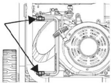
- Release the top and bottom clips then remove the air filter cover.
natural_image
Technical line drawing of a mechanical assembly with no visible text or symbols- Remove the air filters. Use compressed air to clean the coarse air filter.
Note: The foam air filter element is oil soaked. Use an appropriate cleaning container.
NOTICE
Avoid skin contact with engine oil. Wear protective clothing and equipment. Wash all exposed skin with soap and water.
- Remove the foam air filter and wash it by submerging the element in a solution of household detergent soap and warm water. Slowly squeeze the foam to thoroughly clean.
NOTICE
DO NOT twist or tear the foam air filter element during cleaning or drying. Only apply slow but firm squeezing action.
- Rinse the air filter element by submerging it in fresh water and applying a slow squeezing action. Allow the filter to dry thoroughly.
NOTICE
DO NOT pollute. Follow the guidelines of the EPA or other governmental agencies for proper disposal of hazardous materials. Consult local authorities or reclamation facility.
- Dip the foam air filter in clean engine oil then squeeze
out all excess oil. The engine will smoke when started if too much oil is left in the filter.
- Install the foam air filter in the housing, then the coarse air filter. Install the air cleaner cover and secure with the cover clips.
ENGINE OIL LEVEL CHECK
CAUTION
Avoid skin contact with engine oil. Wear protective clothing and equipment. Wash all exposed skin with soap and water.
NOTICE
ALWAYS use the specified engine oil. Failure to use the specified engine oil can cause accelerated wear and/or shorten the life of the engine.
When using the generator under extreme, dirty, dusty conditions or in extremely hot weather, change the oil more frequently.
Ambient air temperature will affect engine oil performance. Change the type of engine oil used based on weather conditions.
heatmap
Recommended Engine Oil Type | Type | 5W-30 | 10W-30 | 5W-30 Synthetic | |---|---|---|---| | Ambient temperature | -20 | 0 | 20 | | Ambient temperature | -28.9 | -17.8 | -6.7 | | Ambient temperature | 40 | 60 | 4.4 | | Ambient temperature | 60 | 80 | 15.6 | | Ambient temperature | 80 | 100 | 15.6 | | Ambient temperature | 26.7 | 37.8 | 26.7 | | Ambient temperature | 10W-40 | 120 | 37.8 | | Ambient temperature | 48.9 | | 48.9 |Check the engine oil level before each use or every 8 hours of operation.
- Place the generator on a level surface and allow the engine to cool for several minutes.
- With a damp rag, clean around the oil dipstick.
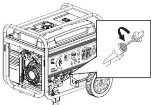
- Remove the oil dipstick and wipe the dipstick clean.
natural_image
Line drawing of a portable electricity generator with a hand holding a tool, showing internal components and a close-up of the motor (no text or symbols present)- Wipe the dipstick clean, then insert it into the oil filler neck without screwing it in. Remove the dipstick and verify that the oil level is within safe operating range between the low (L) and high (H) marks on the dipstick.
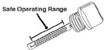
- If low, add recommended engine oil incrementally and recheck until the level is between the L and H marks on the dipstick. DO NOT overfill. If over the full mark on the dipstick, drain the oil to reduce the oil level to the full mark.
- Replace the oil dipstick and hand-tighten.
ENGINE OIL CHANGE
When using the generator under extreme, dirty, dusty conditions or in extremely hot weather, change the oil more frequently. Change the oil while the engine is still warm from operation.
- Place the generator on a level surface and allow the engine to cool for several minutes.
- With a damp rag, clean around the oil dipstick. Remove the dipstick and wipe clean.
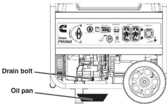
- Place an oil pan (or suitable container) under the oil drain bolt.
- Using a 10mm wrench, remove the oil drain bolt and allow the oil the to drain.
- Install the oil drain bolt and tighten securely.
Note: A new oil drain plug crush washer is recommended at each oil change.
- Slowly pour oil into the oil filler neck until oil the level is between the L and H marks on the dipstick. Stop frequently to check the oil level. DO NOT overfill.
Maximum oil capacity: 1.16 Quart (1.1 Liter)
- Install the oil dipstick and hand-tighten.
NOTICE
DO NOT pollute. Follow the guidelines of the EPA or other governmental agencies for proper disposal of hazardous materials. Consult local authorities or reclamation facility.
SPARK PLUG MAINTENANCE
Inspect and clean the spark plug after every 100 hours of use or six months. Replace the spark plug after 300 hours of use or every year.
- Place the generator on a level surface and allow the engine to cool.
- Remove the spark plug boot by firmly pulling the spark boot directly away from the engine.
- Clean the area around the spark plug.
- Remove the spark plug with the included spark plug socket wrench.
NOTICE
NEVER apply any side load or move the spark plug laterally when removing the spark plug.
- Inspect the spark plug. Replace if electrodes are pitted, burned, or the insulator is cracked. Only use a recommended replacement plug.
- Measure the spark plug electrode gap with a wire-type feeler gauge. If necessary, correct the gap by carefully bending the side electrode.
Spark plug gap: 0.024 - 0.032 in. (0.60 - 0.80 mm)
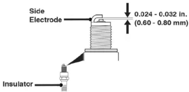
- Carefully install the spark plug finger tight, then tighten as additional 3/8 to 1/2 turn with the spark plug wrench.
- Attach the spark plug boot.
SPARK ARRESTOR SERVICE
Allow the muffler to cool completely before servicing the spark arrestor. Check and clean the spark arrestor after every 100 hours of use or six months. Failure to clean the spark arrestor will result in degraded engine performance.
- Place the generator on a level surface.
- Remove the cover screws and the muffler cover. Use a screw driver to remove the spark arrestor.
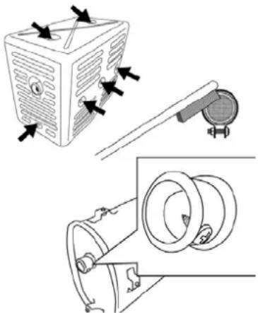
natural_image
Technical line drawing showing a refrigerator, a mechanical device, and a cylindrical component (no text or symbols)- Carefully remove the carbon deposits from the spark arrestor screen with a wire brush. The spark arrestor must be free of breaks and tears. Replace the spark arrestor if damaged.
- Reinstall the spark arrestor and muffler cover.
FUEL FILTER
Replace the fuel filter after 100 hours of use.
Note: Have an appropriate gasoline container and rags ready to catch residual fuel in the filter and fuel line.
- Allow the generator to cool completely.
- Turn the fuel valve to the OFF position.
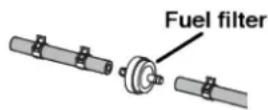
- Note the orientation of the fuel filter. Using pliers, remove the fuel line clamps and remove the fuel filter.
- Install the new fuel filter in the reverse order of removal.
BATTERY MAINTENANCE
The battery shipped with the generator has been fully charged. A battery may lose some charge when not in use for prolonged periods of time.
Note: Once started, the generator will charge the battery after 30–60 minutes of use.
The included trickle charger can remain connected and will maintain the battery for an indefinite period of time. A red light on the charger indicates charging in progress. A green light indicates charging complete. Charge in a dry location.
- Plug the charger into the battery charging port on the control panel.
- Plug the wall receptacle end of the battery charger into a 120 Volt AC wall outlet.
BATTERY REPLACEMENT
WARNING
Burn hazard. The battery contains sulfuric acid (electrolyte) which is highly corrosive and poisonous. Wear protective clothing and eye protection when working near the battery. Keep children away from the battery.
CAUTION
Battery posts, terminals contain lead and lead compounds. Wash hands after handling.
- Loosen and remove the bolt on the battery hold-down plate and swing the plate out.
- Disconnect the quick-connect plugs and remove the battery from the unit.
- Disconnect the quick-disconnect cable leads from the battery.
- On the replacement battery, connect the white (-) quick-connect cable to the battery negative terminal. Slide the rubber boot over the connection hardware.
- Connect the red (+) quick-connect cable to the battery positive terminal. Slide the rubber boot over the connection hardware.
- Install the battery into the generator. Reinstall the battery hold-down plate and tighten the bolt.
- Connect the quick-connect plug.
NOTICE
Dispose of the used battery properly according to the guidelines established by your local or state government.
STORAGE
Proper storage preparation is required for trouble-free operation and generator longevity.
NOTICE
Gasoline stored for as little as 30 days can deteriorate, causing gum, varnish, and corrosive buildup in fuel lines, fuel passages, and the engine. This corrosive buildup restricts the flow of fuel, which can prevent the engine from starting after a prolonged storage period. The use of fuel stabilizer significantly increases the storage life of gasoline. Full-time use of fuel stabilizer is recommended. Follow the manufacturer's instructions for use.
STORAGE TIME RECOMMENDED PROCEDURE
| Less than 1 month No | service required. |
| 2 to 6 months | Fill with fresh gasoline and add gasoline stabilizer. Drain the carburetor float bowl. |
| 6 months or longer | Drain the fuel tank and carburetor float bowl. |
SHORT TERM STORAGE
- Allow the generator to cool a minimum of 30 minutes before storage.
- If operating on LPG, turn the propane tank valve to the fully closed position and disconnect the LPG/propane hose from the generator and propane tank.
- Replace all protective covers on the generator control panel.
- Wipe the generator with a moist cloth. Clean any debris from the muffler cooling vents.
- Store the generator in a well-ventilated, dry location away from sparks, open flames, pilot lights, heat, and other sources of ignition such as areas with a spark-producing electric motor or where power tools are operated.
- DO NOT store the generator, gasoline, or propane tanks near furnaces, water heaters, or any other appliances that produce heat or have automatic ignitions.
- With the engine and exhaust system cool and all surfaces dry, cover the generator to keep out dust. DO NOT use a plastic sheet as a dust cover. Non-porous materials trap moisture and promote rust and corrosion.
LONG TERM STORAGE
Even properly stabilized fuel can leave residue and cause corrosion if left long term. If storing the generator for two to six months, drain the float bowl to prevent gum and varnish buildup in the carburetor.
DRAINING THE FLOAT BOWL
- Turn the fuel tank valve to the OFF position.
- Locate the drain screw on the bottom of the carburetor float bowl.
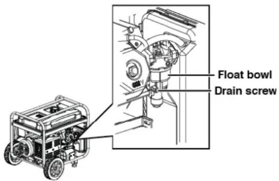
- Place an appropriate gasoline container under the drain screw to catch the drained fuel.
- Loosen the float bowl drain screw and allow the fuel to drain. Tighten the float bowl drain screw.
DRAINING THE FUEL TANK
If storing the generator for longer than six months, drain the fuel tank to prevent fuel separation, deterioration, and deposits in the fuel system.
- Unscrew the fuel tank cap. Remove the fuel screen filter by slightly compressing it while removing it from the tank.
- Using a commercially available gasoline hand pump (not included), siphon the gasoline from the fuel tank into an approved gasoline container. DO NOT use an electric pump.
- Reinstall the fuel screen filter and the fuel tank cap.
- Start the generator and allow it to run until the generator engine stops.
- Push the battery switch to the OFF position.
- Disconnect the battery quick-connect plugs.
- Remove the spark plug.
- Put a teaspoon of engine oil into the cylinder and pull the recoil handle until resistance is felt. At this position the piston is coming up on its compression stroke and both
valves are closed. Storing the engine in this position will help prevent internal corrosion. Return the recoil handle gently.
- Reinstall the spark plug. Leave the spark plug boot disconnected to prevent accidental starting.
VALVE CLEARANCE
NOTICE
Checking and adjusting valve clearance must be done when the engine is cold.
- Remove the rocker arm cover and carefully remove the gasket. If the gasket is torn or damaged, it must be replaced.
- Remove the spark plug so the engine can be rotated more easily.
- Rotate the engine to top dead center (TDC) by pulling the recoil handle slowly. Looking through the spark plug hole, the piston should be at the top (both valves are closed).
- Both the rocker arms should be loose at TDC on the compression stroke. If they are not, rotate the engine 360°.
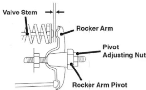
- Insert a feeler gauge between the rocker arm and the valve stem to measure valve clearance.
Intake Valve Exhaust Valve
| Valve Clearance | 0.0031 – 0.0047 in(0.08 – 0.12 mm) | 0.0051 – 0.0067 in(0.13 – 0.17 mm) |
| Torque 8-12 N·m 8-12 N·m | ||
- If an adjustment is necessary, hold the rocker arm pivot and loosen the pivot adjusting nut.
- Turn the rocker arm pivot to obtain the specified clearance. Hold the rocker arm pivot and re-tighten the pivot adjusting nut to the specified torque.
Torque: 106 inch-pound (12 N·m)
- Perform this procedure for the other valve.
- Install the gasket, rocker arm cover, and spark plug.
HIGH-ALTITUDE KIT INSTALLATION GUIDE
The P9500DF requires TWO kits for high-altitude installation: the high-altitude kit, and the propane regulator jet altitude kit. Instructions for both are included here.
WARNING
Before performing any maintenance make sure the engine is cold and the boot is removed from the spark plug.
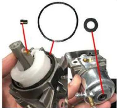
INCLUDED IN THE CARBURETOR KIT
natural_image
Close-up of a mechanical component with red annotations pointing to features (no visible text or symbols)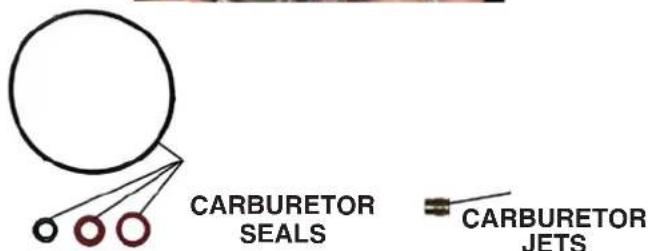
THREE DIFFERENT CARBURETOR JETS INCLUDED


JET A 2000-3000ft.
JET B 3000-6000ft.
JET C 6000-7000ft.
HIGH-ALTITUDE KITS FOR 224CC DUAL FUEL INVERTER
CARBURETOR JET KIT
Part no. (518913-01)/A058V024.
| Altitude Range Letter on Jet | |
| 2000-3000ft A | |
| 3000-6000ft B | |
| 6000-7000ft C | |
NOTICE
This high-altitude kit is to be ove 2000 feet.
At elevations above 7000 feet, the engine may experience decreased performance, even with the high-altitude kit.
If the carburetor is replaced, the proper high-altitude kit jet will need to be installed into the replacement carburetor.
The warranty may be void if necessary adjustments are not made for high altitude use.
DO NOT throw away any carburetor jets. You may need them again if you change altitude of operation.
INSTALL THE HIGH-ALTITUDE KIT
- Make sure engine is off and the generator is cold.
- Drain all fuel from the fuel tank and carburetor float.
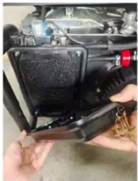
- Remove the air filter cover by unlocking the two locks and pulling off.
natural_image
Close-up of hands using a tool to adjust or install a black engine component (no visible text or symbols)- Remove the foam filter holder by removing the 6 pcs bolts.

natural_image
Close-up of a black industrial fan or motor component with visible internal structure and mounting bracket (no text or symbols)- Remove bolt holding air filter assembly to the engine 9. Remove the wire tie and wire clamp that fix the tube and block. wire harness.
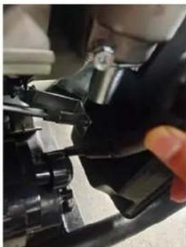
natural_image
Close-up of mechanical components with no visible text or symbols- Pull out the breather tube from air filter assembly and then remove the air filter base.
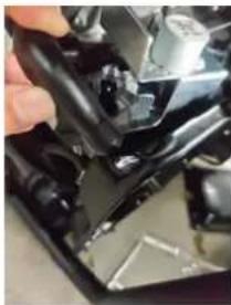
natural_image
Close-up of a hand holding a black mechanical component with a metallic bracket (no visible text or symbols)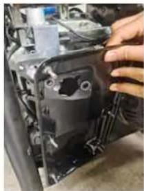
natural_image
Close-up of hands installing or adjusting a mechanical component with visible wiring and mounting holes (no text or symbols)- Remove the stepper motor assembly and air gasket.
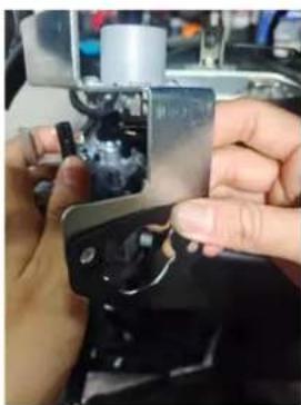
natural_image
Close-up of hands assembling a mechanical component with a metallic bracket (no visible text or symbols)- Remove the throttle lever and the spring C.
natural_image
Close-up of a hand adjusting a mechanical component with visible gears and shafts (no text or symbols)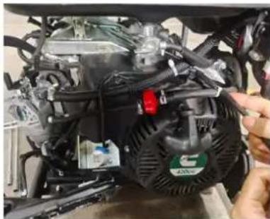
natural_image
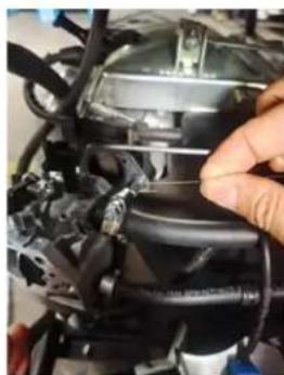
Close-up of a car engine bay with visible components and a hand adjusting the valve (no text or symbols)- Remove the low pressure hose and the fuel hose by squeezing the clamp and pulling off.
natural_image
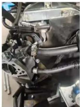
Close-up of a mechanical assembly with hoses and components (no visible text or symbols)- Remove the bolt on the bottom of the carburetor float.
WARNING There may be some gasoline left in the float. Place a container under it to catch any remaining fuel.
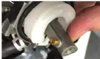
- Using a flat head screwdriver, remove the side jet. Install the proper high altitude jet on the carburetor, and assemble the carburetor properly. The torque of bolt on carburetor is 8-10 N-m (70.81-88.51 in-lb). DO NOT DISCARD OLD CARBURETOR JET.
natural_image
Close-up of a hand adjusting a white plastic pipe fitting with a metallic pipe fitting (no visible text or symbols)-
Reinstall float bowl gasket and then reinstall the float bowl. If the gasket is worn use the replacement included.
-
Reinstall the carburetor and work back from step 10 to reassemble.
NOTE: If your carburetor is adjusted for high altitude do not use at low altitude as the generator will run too lean and damage the engine.
INSTALL THE PROPANE REGULATOR JET ALTITUDE KIT
Installation guide for propane regulator jet altitude kit for Cummins P9500 generator.
WARNING
Before performing any maintenance make sure the engine is cold and the boot is removed from the spark plug.
This high-altitude kit is to be used at elevations above 2000 feet.
- At elevations above 7000 feet, the engine may experience decreased performance, even with the high-altitude kit.
- If the carburetor is replaced, the proper high-altitude kit jet will need to be installed into the replacement carburetor.
- The warranty may be void if necessary adjustments are not made for high altitude use.
- DO NOT throw away any carburetor jets. You may need them again if you change altitude of operation.
PROPANE REGULATOR KIT FOR 420CC GASOLINE GENERATOR
Determine the correct kit from the date of manufacture found in the serial number.
Example:
A058U9671219172800811
| Manufactured before 7/19 Part No. A058V085 | |
| Altitude Range Fitting | Number |
| 0-2000ft Not required | |
| 2000-3000ft 4.2 | |
| 3000-5000ft 4.1 | |
| 5000-6000ft 4.0 | |
| 6000-7000ft 3.9 | |
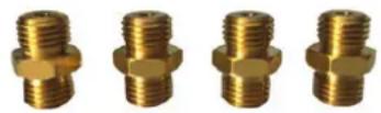 2,000-3,000ft 3,000-5,000ft 5,000-6,000ft 6,000-7,000ftJET 4.2 JET 4.1 JET 4.0 JET 3.9 2,000-3,000ft 3,000-5,000ft 5,000-6,000ft 6,000-7,000ftJET 4.2 JET 4.1 JET 4.0 JET 3.9 | |
2,000-3,000ft 3,000-5,000ft 5,000-6,000ft 6,000-7,000ft JET 4.2 JET 4.1 JET 4.0 JET 3.9
| Manufactured 7/19 and later | Part No. A065P007 |
| Altitude Range Fitting | Number |
| 0-2000ft Not required | |
| 2000-3000ft 5.6 | |
| 3000-5000ft 5.4 | |
| 5000-6000ft 5.2 | |
| 6000-7000ft 5.0 | |
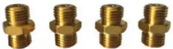 2,000-3,000ft 3,000-5,000ft 5,000-6,000ft 6,000-7,000ftJET 5.6 JET 5.4 JET 5.2 JET 5.0 2,000-3,000ft 3,000-5,000ft 5,000-6,000ft 6,000-7,000ftJET 5.6 JET 5.4 JET 5.2 JET 5.0 | |
2,000-3,000ft 3,000-5,000ft 5,000-6,000ft 6,000-7,000ft JET 5.6 JET 5.4 JET 5.2 JET 5.0
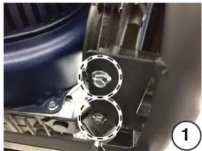
- Remove two bolts under propane regulator to remove it from its mount.
- Remove propane connection from top regulator.
- Remove jet from top of regulator.
- Pick correct propane jet for desired altitude and install.
- Reconnect propane connection at the top of the regulator.
- Reinstall bolts on bottom of the regulator to secure it to the frame.
- Make sure connections are air tight. Test with soapy water to make sure there are no leaks.
natural_image
Close-up of a mechanical component with circular features and a numbered label (1) in the corner, no readable text or symbols present.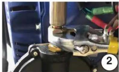
natural_image
Close-up of mechanical components with no visible text or symbols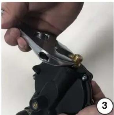
natural_image
Close-up of hands using a pliers to handle a mechanical component (no visible text or symbols)HIGH ALTITUDE REGULATOR FITTING KIT INSTALLATION
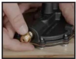
- Replace the brass jet on your propane regulator with the appropriate model that came with your kit. Use an adjustable wrench to tighten.
- Choose the appropriate jet for your altitude.
- Move the generator to a well-ventilated location, start the generator, and make sure it's running properly.
natural_image
Close-up of hands adjusting a small mechanical component with a golden fitting (no visible text or symbols)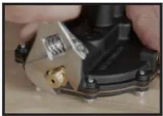
natural_image
Close-up of hands using a tool to adjust or install a mechanical component (no visible text or symbols)| PROBLEM POSSIBLE CAUSE CORRECTION | ||
| Engine will not start | Battery switch in the OFF position. Turn battery switch to the ON position. | |
| Out of fuel. Refuel. | ||
| Bad fuel, generator stored without treating or draining gasoline, or refueled with bad gasoline. | Drain the fuel tank. Refuel with fresh gasoline. | |
| Dirty air filter. Clean the air filter. | ||
| Low engine oil level stopped generator. | If low oil LED illuminated, turn battery switch to the OFF position. Add engine oil. | |
| Spark plug wet with fuel (flooded engine). | Wait five minutes. Turn battery switch to the OFF position. Pull recoil handle rapidly several times. If the generator does not start, remove spark plug and dry. | |
| Spark plug faulty, fouled, or improperly gapped. Gap or replace the spark plug. Reinstall. | ||
| Fuel filter restricted, fuel system malfunction, fuel pump failure, ignition malfunction, valves stuck, etc. | Contact Cummins support toll-free at 1-800-CUMMINS | |
| Battery drained. | Use the recoil handle to start the generator. | |
| Charge the battery. | ||
| Choke partially open or closed due to weak or disconnected battery. | Manually set the choke. See Maintenance section. | |
| Engine starts, then shuts down | Out of fuel. Refuel. | |
| Incorrect engine oil level. Check engine oil level. | ||
| Dirty air filter. Clean the air filter. | ||
| Contaminated fuel. Drain the fuel tank. Refuel with fresh gasoline. | ||
| Defective low oil level switch. | Contact Cummins support toll-free at 1-800-CUMMINS | |
| Engine lacks power | Air filter restricted. Clean or replace air filter. | |
| Bad fuel, generator stored without treating or draining gasoline, or refueled with bad gasoline. | Drain the fuel tank. Refuel with fresh gasoline. | |
| Fuel filter restricted, fuel system malfunction, fuel pump failure, ignition malfunction, valves stuck, etc. | Contact Cummins support toll-free at 1-800-CUMMINS | |
| Engine runs rough or bogs when load applied | Dirty air filter. Clean the air filter. | |
| Generator overloaded. Unplug some devices. | ||
| Faulty power tool or appliance. | Replace or repair tool or appliance. Stop and restart the engine. | |
| Fuel filter restricted, fuel system malfunction, fuel pump failure, ignition malfunction, valves stuck, etc. | Contact Cummins support toll-free at 1-800-CUMMINS | |
| No power at AC receptacles | OUTPUT READY LED is OFF and OVERLOAD LED is ON. | Check AC load. Stop and restart engine. |
| Check the air inlet. Stop and restart the engine. | ||
| AC circuit breaker/s tripped. Check AC loads and reset circuit breaker/s. | ||
| Faulty power tool or appliance. | Replace or repair tool or appliance. Stop and restart the engine. | |
| Faulty generator. | Contact Cummins support toll-free at 1-800-CUMMINS | |
| Frost on the propane tank or regulator | If the temperature of the propane tank drops below the dew point, condensation on the tank may turn to frost or ice. This typically occurs in humid conditions. | Providing all the propane fuel handling equipment is functioning normally, no correction is needed. |
| The Propane tank is not equipped with an Overfilling Prevention Device (OPD). | If you suspect your propane fuel tank is not equipped with an OPD device, discontinue operation immediately and replace the propane fuel tank with a propane tank equipped with a an OPD. | |
| Propane fuel tank overfilled. | If you suspect your propane fuel tank has been overfilled, discontinue operation immediately and return the propane fuel tank to the place of purchase or refilling. | |
| Propane fuel smell | Fuel regulator or fuel hose and fittings not securely sealed. | Using a soap solution check each connection and tighten as needed. |
| Propane fuel regulator vent active. | The propane fuel regulator is equipped with a vent that will allow a small amount of propane fuel vapor to escape from the regulator when the propane tank valve is opened. This can be normal providing the venting of the propane is brief. If you suspect that this is abnormal, immediately discontinue use and have the propane regulator inspected by a qualified technician. | |
| Residual fuel from the carburetor dispersing after operation. | Normal, no correction is needed. |
| Poor performance or engine stalling on Propane | Propane fuel line kinked or crushed. | Inspect propane fuel line and remove kinks or other obstructions. |
| Fuel selector valve not properly positioned. | Rotate the fuel valve fully until the pointer is directly in line with the desired fuel. | |
| Gasoline not purged from the carburetor before switching to propane. | Close the propane fuel tank valve. Move the fuel selector switch to gas. Start the engine and allow the engine to run until the gasoline has been consumed in the carburetor. Begin propane start up procedure. |
EXPLODED VIEWS AND PARTS LISTS
ENGINE EXPLODED VIEW
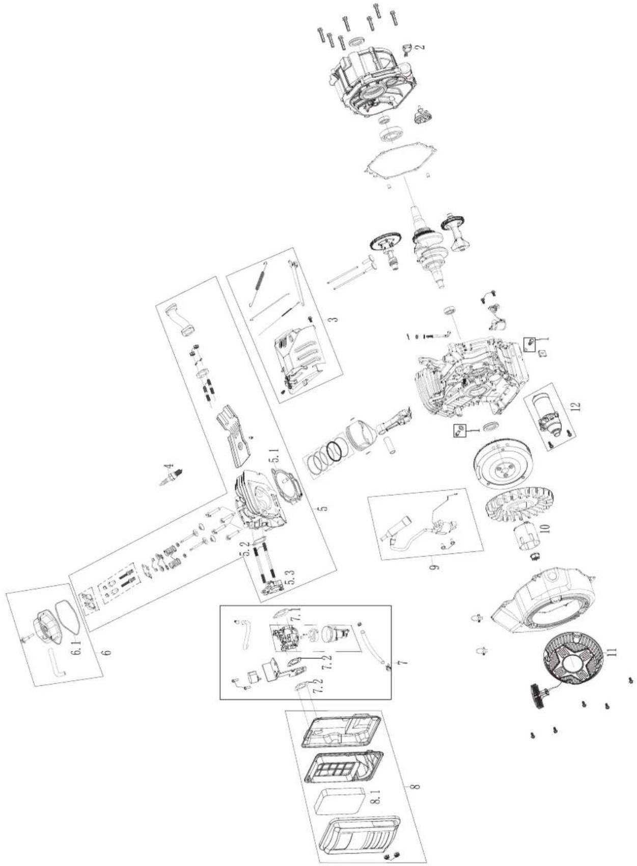
ENGINE PARTS LIST
| NO. PART# DESCRIPTION | |
| 1 A076 | L625 OIL DRA NAGE BOLT GROUP |
| 2 A064 | N167 DIPSTICK ASSEMBLY |
| 3 A076 | L626 SPEED GOVERNOR KIT ASSEMBLY |
| 4 A064 | D660 SPARK PLUG |
| 5 A076 | L627 CYLINDER HEAD KIT ASSEMBLY |
| 5.1 | A064D650 CYLINDER HEAD GASKET |
| 5.2 | A064D646 INTAKE GASKET |
| 5.3 | A064D775 CAP BURETOR CONNECTION BLOCK |
| 6 A076 | L628 CYLINDER HEAD COVER KIT ASSEMBLY |
| 6.1 | A058V139 CYLINDER HEAD COVER GASKET |
| NO. PART# DESCRIPTION | |
| 7 A076L629 CARBURETOR KIT ASSEMBLY | |
| 7.1 A064D647 CAFBURETOR GASKET | |
| 7.2 A064D649 AIR FILTER GASKET | |
| 8 A076L630 AIR FILTER KIT ASSEMBLY | |
| 8.1 A064D487 AIR FILTER | |
| 9 A076L631 IGNITER KIT ASSEMBLY | |
| 10 A064D785 STARTER PULLEY | |
| 11 A076L632 START PULLER(RECOIL COVER) | |
| 12 A076L633 STARTER MOTOR KIT ASSEMBLY |
GENERATOR EXPLODED VIEW
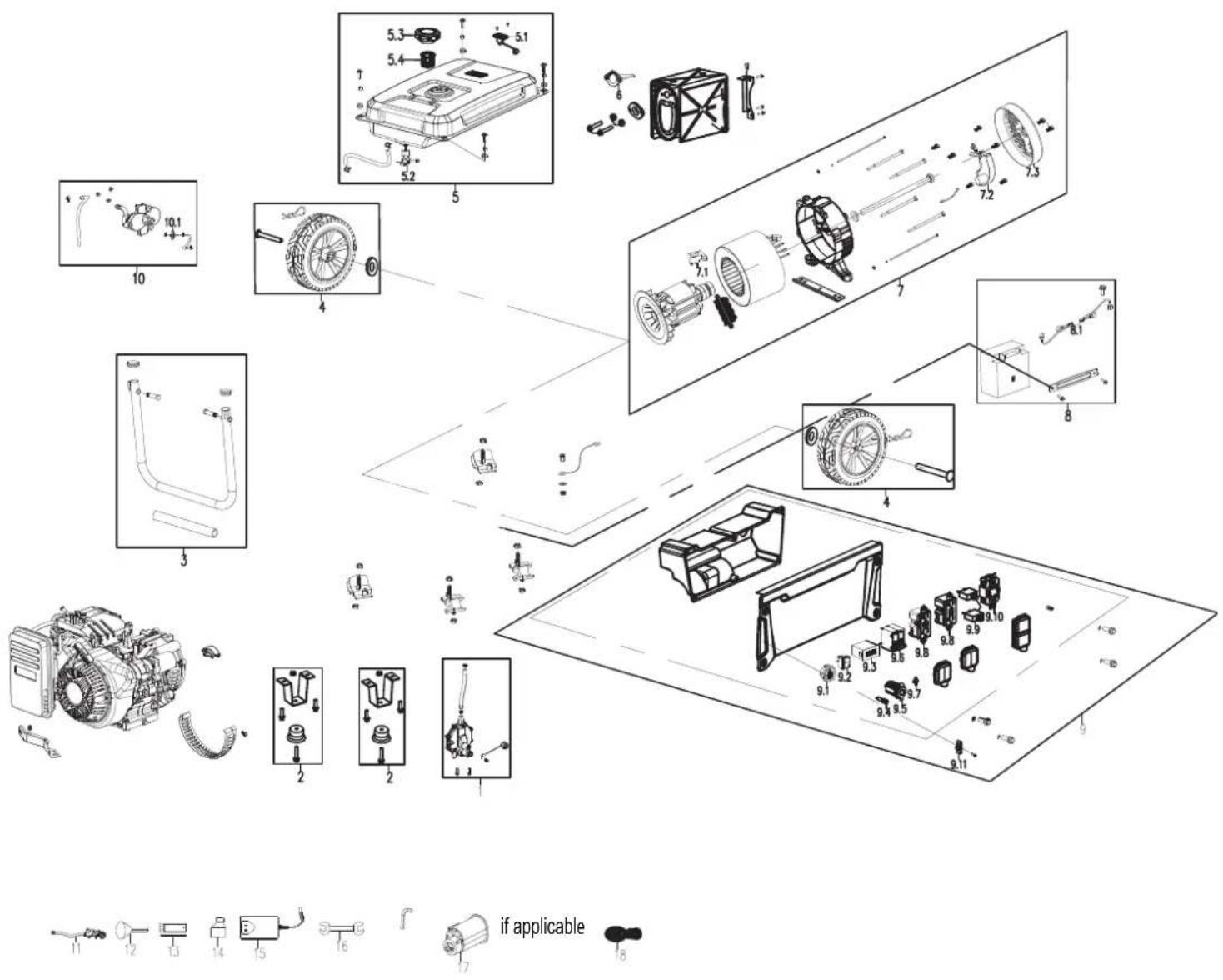
GENERATOR PARTS LIST
| NO. PART# DESCRIPTION | ||
| 1 A076L | 634 PRESSURE | REDUCING VALVE KIT ASSEMBLY |
| 2 A076L | 638 FOOT BRACKET | KIT ASSEMBLY |
| 3 A076L | 639 HANDLE WELDING | KIT ASSEMBLY |
| 4 A076L | 642 WHEEL KIT ASSEMBLY | |
| 5 A076L | 643 FUEL TANK KIT ASSEMBLY | |
| 5.1 A076L | 646 FUEL GAUGE | |
| 5.2 A064 | N127 FUEL SWITCH | |
| 5.3 A064 | N129 FUEL CAP | |
| 5.4 A064 | N128 FUEL TANK FILTER | |
| 6 A076L | 647 SPARK ARRESTER | |
| 7 A076L | 648 ALTERNATOR | KIT ASSEMBLY |
| 7.1 A058 | V107 CARBON BRUSH | |
| 7.2 A064 | N140 AVR | |
| 7.3 A064 | N191 ALTERNATOR | TAIL COVER |
| 8 A076L | 651 BATTERY BRACKET | KIT ASSEMBLY |
| 8.1 A064 | N123 BATTERY WIRING ASSEMBLY | |
| NO. PART# DESCRIPTION | ||
| 9 A076L | 652 PANEL KIT ASSEMBLY | |
| 9.1 A076L | 654 ONE PUSH | BOTTON SWITCH |
| 9.2 A064D | 498 ENGINE SWITCH | |
| 9.3 A064D | 492 TIME ACCUMULATOR | |
| 9.4 A064D | 496 POWER INDICATOR | |
| 9.5 A064D | 503 DOUBLE USB DC SOCKET | |
| 9.6 A064D | 500 BREAKER 31A | |
| 9.7 A058V | 047 BATTERY CHARGING PORT 2.5MM | |
| 9.8 A064N | 196 R5-20 GFC | |
| 9.9 A064N | 198 20A THERMAL PROTECTOR | |
| 9.10 A064N | 197 L14-30 RECEPTACLE | |
| 9.11 A064N | 150 SWITCH TURNTABLE ASSEMBLY | |
| 10 A076L | 658 DUAL FUEL SELECTOR SWITCH | |
| 10.1 A064N | 124 FILTER | |
| 11 A076L | 659 PRESSURE REDUCING VALVE | |
| 12 A076L | 660 FUNNEL | |
| 13 A058U | 962 SPARK PLUG SLEEVE | |
| 14 A076L | 661 OIL BOTTLE ASSEMBLY | |
| 15 A064N | 122 CHARGER | |
| 16 A076L | 662 WRENCH | |
| 17 | A064N194 CARBON CANISTER ASSEMBLY(IF APPLICABLE) | |
| 18 | A058M291 REMOTE KEY | |
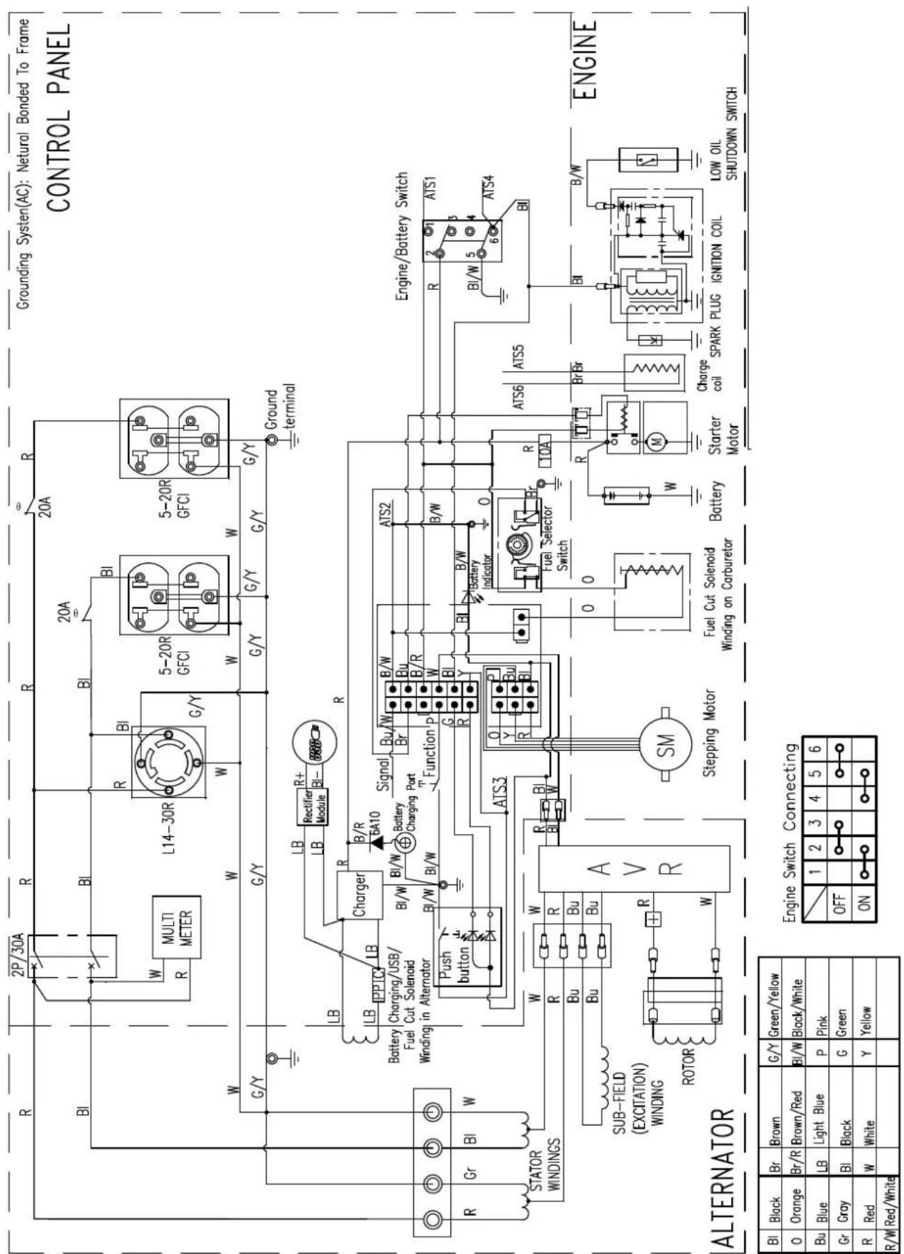
Onan P9500df
INSTALE PIES Y RUEDAS ....46
LLENADO DE ACEITE INICIAL 47
COMBUSTIBLE 47
DANGER As the owner's manual and fellow addeely procedures prior to operating the generators, follows to follow these instructions may lead to serious injury, property damage or death. Never add heat to generator when the engine is hot or running, Never add heat to some in contact with running engine or hot generator parts. Always silver engine to cool down before adding heat. Never touch hot surface. Generators pore risk of shock absolutely. It operated in damp or wet conditions. Keep generator and stored fuel away from its, sports and cigarettes. Never connect to a building's electrical system unless a transfer switch has been製ated by a certified electrician.
TOXIC FUMES HAZARD. Running engines gives off carbon monoxide, an odourless poisonous gas that can cause nausea, fainting, or death. Do not start engine indoors or in an enclosed area, even if the windows and doors are open.
INSTALE PIES Y RUEDAS
AVISO
other
Tipo de aceite de motor recomendado | Type | 5W-30 | 10W-30 | 5W-30 Synthetic | |---|---|---|---| | -20 | 0 | 20 | 40 | | -17.8 | -6.7 | 4.4 | 15.6 | | 60 | 80 | 100 | 26.7 | | 37.8 | 120 | | | | 48.9 | | | | The chart displays a horizontal bar for the 'Synthetic' component, with each bar labeled by its value and a secondary axis labeled 'F' (°F) and '°C' (°C). The 'Temperatura ambiente' label is positioned below the bars.natural_image
Line drawing of a portable electricity generator with open vent, showing internal components and a hand holding a plug (no text or symbols)flowchart
graph LR
    A["Engine"] --> B{CHoke Cycle}
    B -->|Warm Start OFF| C["Manual Operation of Auto Choke"]
    B -->|Cold Start ON| D["Manual Operation of Auto Choke"]
ARRANQUE DEL MOTOR: GLP
natural_image
Technical line drawing of a mechanical assembly with no visible text or symbolsnatural_image
Line drawing of a portable gas generator with open circuit board and battery, showing internal components and a close-up of the fuse (no text or symbols)natural_image
Technical line drawings of a device with arrows indicating motion, alongside a magnified view of its internal components (no text or symbols)- With the engine and exhaust system cool and all surfaces dry, cover the generator to keep out dust. Do not use a plastic sheet as a dust cover. Non-porous materials trap moisture and promote rust and corrosion.
ALMACENAMIENTO A LARGO PLAZO
natural_image
Close-up of a mechanical component with red annotations pointing to features (no visible text or symbols)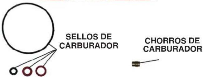
THREE DIFFERENT CARBURETOR JETS INCLUDED

KITS DE GRAN ALTITUD PARA INVERSOR DE COMBUSTIBLE DUAL DE 224CC
natural_image
Close-up of hands installing or adjusting a black engine component with visible wiring and valve (no text or symbols)natural_image
Close-up of a mechanical component with visible wiring and mounting bracket (no text or symbols)natural_image
Close-up of mechanical components with no visible text or symbolsnatural_image
Close-up of a hand using a tool to adjust or install electronic components (no visible text or symbols)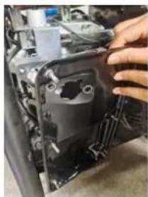
natural_image
Close-up of a hand adjusting a mechanical component with visible wiring and mounting holes (no text or symbols)natural_image
Close-up of hands assembling a mechanical component with visible internal components (no text or symbols)natural_image
Close-up of a hand adjusting a mechanical component with black tubing and a metallic housing (no visible text or symbols)natural_image
Close-up of a car engine bay with visible components and a hand adjusting the valve (no text or symbols)natural_image
Close-up of an automotive engine bay with hoses and components (no visible text or symbols)natural_image
Close-up of a hand adjusting a white plastic hose with a metallic pipe fitting (no visible text or symbols)-
Reinstall float bowl gasket and then reinstall the float bowl. If the gasket is worn use the replacement included.
-
Reinstall the carburetor and work back from step 10 to reassemble.
natural_image
Close-up of mechanical components with circular features and a numbered label (1) in the corner, no readable text or symbols present.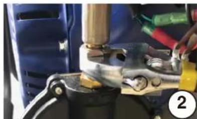
natural_image
Close-up of a mechanical assembly with a tool and clamping mechanism (no visible text or symbols)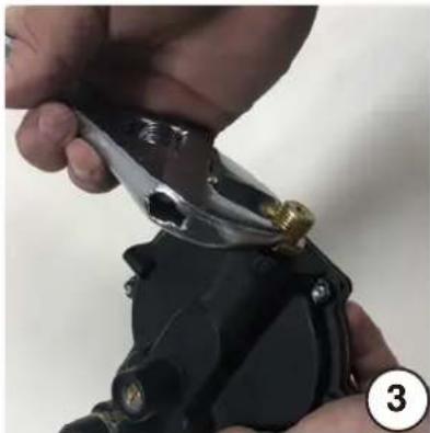
natural_image
Close-up of hands using a pliers to adjust or install a mechanical component (no visible text or symbols)natural_image
Close-up of hands adjusting a mechanical component with a brass fitting (no visible text or symbols)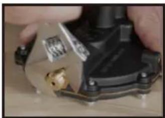
natural_image
Close-up of hands holding a mechanical component with a brass fitting (no visible text or symbols)- Disconnect the spark plug wire to prevent accidental starting.
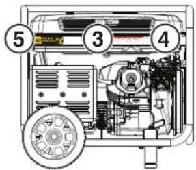
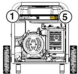
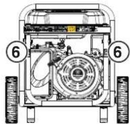



DANGER As the owner's manual and fellow always procedures prefer to spend the generators, flares to cover these instructions may lead to surface (lavy property damage or death, never add fuel to generator when the engine is hot or running, never after fuel to come in contact with running engine or hot generator parts. Always slow engine to cool down before adding fuel. Never touch hot surfaces. Generators power tick of shock especially if operated (damp or wet conditions, Keep generator and stored fuel away from fly, sparts and cigarettes, Never contract to a bughly electric system unless a transfer unit has been installed by a certified electrician).
▲ PELIGRO
TOXIC FUMES HAZARD. Running engines gives off carbon monoxide, an odourless poisonous gas that can cause nausea, fainting, or death. Do not start engine indoors or in an enclosed area, even if the windows and doors are open.
WARNING/ADVERTENCIA /AVERTISSEMENT
natural_image
Mechanical diagram showing a lever mechanism with a curved arrow indicating motion (no text or symbols present)DÉMARRAGE DU MOTEUR: PROPANE
▲ DANGER
If the engine stops when switching fuel sources, disconnect all loads then restart the unit on the fuel source of choice.
ARRÊT DU MOTEUR
Total Starting Watts Needed 2180
DIMENSIONS DU CORDON D'EXTENSION
natural_image
Technical line drawing of a mechanical assembly with no visible text or symbolsDo not pollute. Follow the guidelines of the EPA or other governmental agencies for proper disposal of hazardous materials. Consult local authorities or reclamation facility.
MAINTENANCE DES BOUGIES
natural_image
Technical line drawings of a device with arrows indicating motion, showing front, side, and top views (no text or symbols)Remarque: Once started, the generator will charge the battery after 30–60 minutes of use.
natural_image
Close-up of a mechanical component with red annotations pointing to features (no visible text or symbols)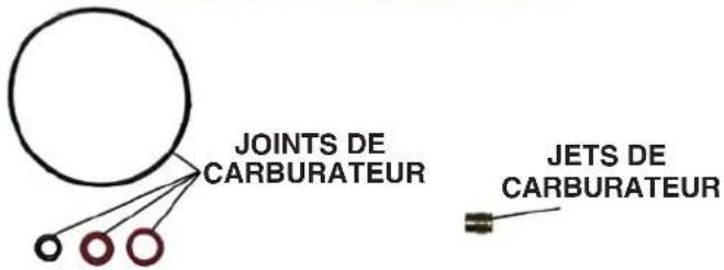
THREE DIFFERENT CARBURETOR JETS INCLUDED
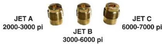
KITS HAUTE ALTITUDE POUR INVERSEUR BI-CARBURANT 224CC
KIT GICLEUR CARBURATEUR
Réf. (518913-01)/A058V024.
| Plage d’altitude Lettre sur Jet | |
| 2000-3000 pi A | |
| 3000-6000 pi B | |
| 6000-7000 pi C | |
AVIS
natural_image
Close-up of hands installing or adjusting a black engine component with a tool (no visible text or symbols)natural_image
Close-up of a mechanical component with visible wiring and mounting bracket (no text or symbols)natural_image
Close-up of mechanical components with no visible text or symbolsnatural_image
Close-up of a hand using a tool to adjust or install electronic components (no visible text or symbols)
natural_image
Close-up of a hand adjusting a mechanical component with visible wiring and mounting brackets (no text or symbols)natural_image
Close-up of hands assembling a mechanical component with a metallic housing (no visible text or symbols)natural_image
Close-up of a hand adjusting a mechanical component with visible gears and shafts (no text or symbols)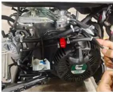
natural_image
Close-up of a car engine bay with visible hoses and components, no text or symbols presentnatural_image
Close-up of an automotive engine component with hoses and springs (no visible text or symbols)natural_image
Close-up of a hand adjusting a white plastic mechanical component with a metallic pipe fitting (no visible text or symbols)natural_image
Three-step photo sequence showing a mechanical assembly with tool, tool tip, and clamp (no visible text or symbols)INSTALLATION DU KIT DE MONTAGE DU RÉGULATEUR À HAUTE ALTITUDE
natural_image
Close-up of hands adjusting a mechanical component with a brass fitting (no visible text or symbols)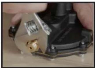
natural_image
Close-up of a hand holding a mechanical component with a brass fitting (no visible text or symbols)DÉPANNAGE
DÉPANNAGE
PROBLÈME CAUSE POSSIBLE CORRECTION
Copyright © 2024 Cummins Inc. All rights reserved.
Cummins, Onan and the "C" logo are registered trademarks of Cummins Inc. and its subsidiaries.
Other company, product, or service names may be trademarks or service marks of others.
Specifications are subject to change without notice.
- Onan P9500df Dual Fuel Portable Generator
- TABLE OF CONTENTS
- INTRODUCTION
- SAFETY
- COMPONENTS
- ASSEMBLY
- OPERATION
- DISCLAIMERS
- MAINTENANCE
- HIGH ALTITUDE KIT
- TROUBLESHOOTING
- EXPLODED VIEWS AND PARTS LISTS
- SCHEMATICS
- ALL RIGHTS RESERVED
- DANGER
- SAVE THESE INSTRUCTIONS
- NOTICE
- PRODUCT REGISTRATION
- For Your Records
- 1-800-CUMMINS
- SAFETY DEFINITIONS
- WARNING
- CAUTION
- SAFETY SYMBOLS
- ⚠️ DANGER
- SAFETY INSTRUCTIONS
- CORRECT USE
- INCORRECT USE
- GENERAL SAFETY PRECAUTIONS
- FUEL SAFETY
- LIQUID PETROLEUM GAS (LPG/PROPANE)
- When starting the generator:
- When transporting or servicing the generator:
- When storing the generator:
- ▲ PELIGRO
- CARTON CONTENTS
- INSTALL FEET AND WHEELS
- INITIAL OIL FILL
- FUEL
- FUEL REQUIREMENTS
- USING FUEL STABILIZER
- FILLING THE FUEL TANK
- CONNECT AN LPG/PROPANE TANK
- CONNECT THE BATTERY
- GENERATOR LOCATION
- GROUNDING
- DISCONNECTING THE BONDED NEUTRAL
- REMOTE START
- PAIRING THE REMOTE START
- Remote replacement batteries: (2) CR2016
- Remote replacement: A058M291
- FUEL SELECTOR SWITCH
- BREAK-IN PERIOD
- BEFORE STARTING THE GENERATOR
- STARTING THE ENGINE: GASOLINE
- STARTING THE ENGINE: PROPANE
- SWITCHING FUEL SOURCES
- GASOLINE TO PROPANE
- PROPANE TO GASOLINE
- STOPPING THE ENGINE
- FREQUENCY OF USE
- AC CIRCUIT BREAKERS
- GENERATOR CAPACITY
- POWER MANAGEMENT
- EXTENSION CORDS
- EXTENSION CORD SIZING
- TRANSPORTING
- MAINTENANCE SCHEDULE
- Before Each Use
- After First 25 Hours or First Month
- After 50 Hours or Every 6 Months
- After 100 Hours or Every 6 Months
- After 300 Hours or Every Year
- MAINTENANCE REPLACEMENT PARTS
- AIR FILTER MAINTENANCE
- ENGINE OIL LEVEL CHECK
- ENGINE OIL CHANGE
- SPARK PLUG MAINTENANCE
- SPARK ARRESTOR SERVICE
- FUEL FILTER
- BATTERY MAINTENANCE
- BATTERY REPLACEMENT
- STORAGE
- SHORT TERM STORAGE
- LONG TERM STORAGE
- DRAINING THE FLOAT BOWL
- DRAINING THE FUEL TANK
- VALVE CLEARANCE
- Torque: 106 inch-pound (12 N·m)
- HIGH-ALTITUDE KIT INSTALLATION GUIDE
- HIGH-ALTITUDE KITS FOR 224CC DUAL FUEL INVERTER
- CARBURETOR JET KIT
- INSTALL THE HIGH-ALTITUDE KIT
- INSTALL THE PROPANE REGULATOR JET ALTITUDE KIT
- PROPANE REGULATOR KIT FOR 420CC GASOLINE GENERATOR
- HIGH ALTITUDE REGULATOR FITTING KIT INSTALLATION
- GENERATOR EXPLODED VIEW
- GENERATOR PARTS LIST
- Onan P9500df
- INSTALE PIES Y RUEDAS
- AVISO
- ARRANQUE DEL MOTOR: GLP
- ALMACENAMIENTO A LARGO PLAZO
- KITS DE GRAN ALTITUD PARA INVERSOR DE COMBUSTIBLE DUAL DE 224CC
- WARNING/ADVERTENCIA /AVERTISSEMENT
- DÉMARRAGE DU MOTEUR: PROPANE
- ▲ DANGER
- ARRÊT DU MOTEUR
- DIMENSIONS DU CORDON D'EXTENSION
- MAINTENANCE DES BOUGIES
- KITS HAUTE ALTITUDE POUR INVERSEUR BI-CARBURANT 224CC
- AVIS
- INSTALLATION DU KIT DE MONTAGE DU RÉGULATEUR À HAUTE ALTITUDE
- DÉPANNAGE
Brand : Cummins
Model : Onan P9500df
Category : Generator