LK500Ti - Treadmills BH FITNESS - Free user manual and instructions
Find the device manual for free LK500Ti BH FITNESS in PDF.


User questions about LK500Ti BH FITNESS
0 question about this device. Answer the ones you know or ask your own.
Ask a new question about this device
Download the instructions for your Treadmills in PDF format for free! Find your manual LK500Ti - BH FITNESS and take your electronic device back in hand. On this page are published all the documents necessary for the use of your device. LK500Ti by BH FITNESS.
USER MANUAL LK500Ti BH FITNESS
Important: Read all instructions carefully before using this product.
Register your product warranty online at: www.BHFitnessUSA.com.
Retain this owner's manual for future reference.
natural_image
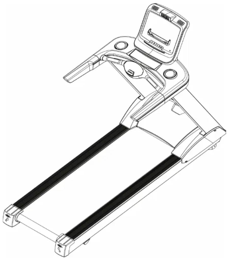
Line drawing of a treadmill with control panel and side-mounted tray (no text or symbols)
TABLE OF CONTENTS
Title Page
Congratulations....02
Maintenance and Cleaning ..... 02
Safety Information 03
Grounding Instructions ..... 04
Exercise Instruction 05
Training Guidelines 06
Suggested Stretches ..... 10
Assembly Instructions.... 12
Console Operations .....19
Exploded View Drawing.... 31
Parts List....32
Warranty 34
French / Français 35
CONGRATULATIONS
Congratulations on your purchase of BH Fitness equipment. We hope you appreciate the style, quality, and value that exercisers around the world have come to expect from BH Fitness.
If you have any questions, concerns or product issues please call our Customer Service Team at 1-866-325-2339 or email us at CustomerSupport@BHNorthAmerica.com.
Carefully read through the instructions contained in this manual. They provide you with important information about assembly, safety, fi ness and use of the machine. Please read ALL the safety information contained on the following page.
MAINTENANCE AND CLEANING
Care has been taken to assure that your equipment has been properly adjusted and lubricated at the factory. It is not recommended that the user attempt service on the internal components. Instead, seek service from an authorized service center. However, you may clean the outer surface. Use a soft cloth, dampened with warm water. Do not use aerosol sprays or pump bottles as they may deposit sediments upon the console surface. The use of harsh chemicals will destroy the protective coating and cause a static build-up that may damage the some of the components.
SAFETY INFORMATION
PRECAUTIONS
The machine has been designed and constructed to provide maximum safety. Nevertheless, certain precautions should be taken when using exercise equipment. Read the whole manual before assembling and using the machine. Please observe the following safety precautions:
- Keep children and pets away from this equipment at all times. DO NOT leave them unsupervised in the room where the machine is kept.
- If you experience dizziness, nausea, chest pains or any other symptom while using this machine STOP exercising. SEEK IMMEDIATE MEDICAL ATTENTION!
- Use the machine on a level and solid surface. Adjust the feet for stability.
- Keep your hands away from any of the joints and moving parts.
- Wear clothing suitable for doing exercise. Do not wear baggy clothing that might get caught in the machine. Always wear athletic shoes when using the machine and tie the laces securely.
- This machine must only be used for the purposes described in this manual. DO NOT use accessories that are not recommended by BH Fitness.
- Do not place sharp objects near the machine.
- Any person with physical or coordination limitations should not use the machine without the assistance of a qualified person or doctor.
- Do warm-up stretching exercises before using the equipment.
- Do not use the machine if it is not working correctly.
- Before using the machine, thoroughly inspect the equipment for proper assembly.
- Maintain a minimum safety clearance of 12" in the front, 24" on the sides and 79" to the rear of the treadmill.
- Use only authorized and trained technicians if a repair is needed.
- Please follow the advice for correct training, as detailed in the Training Guidelines.
- Use only the tools provided to assemble this machine.
- Replace warning labels if damaged, illegible or removed.
- This machine was designed for a maximum user weight of 450 lbs (204 kg)
- The machine can only be used by one person at a time.
Caution: Consult your doctor before beginning to use the machine or any exercise program.
Read all of the instructions before using any exercise equipment.
KEEP THESE INSTRUCTIONS SAFE FOR FUTURE USE.
GROUNDING INSTRUCTIONS EXERCISE INSTRUCTION
It is important that the product must be grounded first. If a malfunction or breakdown occurs, grounding will provide a path of least resistance for electric current to reduce the risk of electric shock.
The product is equipped with a cord having an equipment-grounding conductor and a grounding plug. The plug must be plugged into an appropriate outlet that is properly installed and grounded in accordance with all local codes and ordinances.
DANGER- Improper connection of the equipment-grounding conductor can result in a risk of electric shock. Check with a qualifi ed electrician or serviceman if you doubt whether the products are properly grounded. Do not modify the plug provided with the product - If it will not fit the outlet, have a proper outlet installed by a qualifi ed electrician.
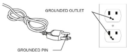
The products is for use on normal 110V-120V circuit and contains a grounded plug that looks like the one illustrated below. Make sure that the product is connected to an outlet having the same configuration as the plug. No adapter should be used with the product.
text_image
GROUNDED OUTLET GROUNDED PINUse of the machine offers various benefits; it will improve fitness, muscle tone and when used in conjunction with a calorie controlled diet, it will help you lose weight.
- Consult your doctor before starting any exercise program. It is advisable to undergo a complete physical examination.
- Work at the recommended exercise level. Do not over exert yourself
- If you feel any pain or discomfort, stop exercising immediately and consult your doctor.
- Wear appropriate clothing and footwear for the exercise; do not wear loose clothing; do not wear leather soled shoes or footwear with high heels.
- It is advised that you do warm-up stretches before working out.
- Step on to the equipment slowly and securely.
- Select the program or workout option that is most closely aligned with your workout interests.
- Start slowly and work your way up to a comfortable pace.
- Be sure to cool down after your workout.
TREADMILL OPERATION
When you are ready to use the treadmill, don't stand on the running belt. First turn on the power, hold the handrails and step on the protective side rails, then press "START" to start the treadmill. When the motor is running at low speed, move your feet with the running belt. Remember to clip the safety key to the waist to avoid dangers resulted from failing or uncomfortable health. Don't start the treadmill with high speed and try to jump onto the running belt. In an emergency, please hold the front handrails or the lateral handrails, and move your feet from the running belt and onto the protective side rails.
TRAINING GUIDELINES TRAINING GUIDELINES
Exercise is one of the most important factors in the overall health of an individual. Listed among its benefits are:
- Increased capacity for physical work (strength endurance)
- Increased cardiovascular (heart and arteries/veins) and respiratory efficiency
• Decreased risk of coronary heart disease
• Changes in body metabolism, e.g. losing weight - Delaying the physiological effects of age
- Reduction in stress, increase in self-confidence, etc.
There are several components of physical fitness and each is defined below.
STRENGTH
The capacity of a muscle to exert a force against resistance. Strength contributes to power and speed.
MUSCULAR ENDURANCE
The capacity to exert a force repeatedly over a period of time, e.g. it is the muscular endurance of your legs to carry you 10 km without stopping.
FLEXIBILITY
The range of motion of your joints. Improving fl exibility involves the stretching of muscles and tendons to maintain or increase suppleness, and it provides increased resistance to muscle injury or soreness.
CARDIO-RESPIRATORY ENDURANCE
The most essential component of physical fitness. It is the efficient functioning of the heart and lungs.
AEROBIC FITNESS
Is an exercise of relatively low intensity and long duration, which depends primarily on the aerobic energy system. Aerobic means "with oxygen", and refers to the use of oxygen in the body's metabolic or energy-generating process. Many types of exercise are aerobic, and by definition are performed at moderate levels of intensity for extended periods of time.
ANAEROBIC TRAINING
Is an exercise intense enough to trigger anaerobic metabolism. This means “without oxygen” and is the output of energy when the oxygen supply is insufficient to meet the body’s long term energy demands. (For example, a 100 meter sprint.)
OXYGEN UPTAKE
The effort that you can exert over a prolonged period of time is limited by your ability to deliver oxygen to the working muscles. Regular vigorous exercise produces a training effect that can increase your aerobic capacity by as much as 20 to 30%. An increased VO2 Max indicates an increased ability of the heart to pump blood, of the lungs to ventilate oxygen, and of the muscles to take up oxygen.
THE TRAINING THRESHOLD
This is the minimum level of exercise which is required to produce significant improvements in any physical fitness parameter.
OVERLOAD
This is where you exercise above your comfort level. The intensity, duration and frequency of exercise should be above the training threshold and should be gradually increased as the body adapts to the increasing demands. As your fit stress level improves, the training threshold should rise. Working through your program and gradually increasing the overload factor is important.
PROGRESSION
As you become more fit, a higher intensity of exercise is required to create an overload and therefore provide continued improvement.
SPECIFICS
Different forms of exercise produce different results. The type of exercise that is carried out is specific to the muscle groups being used and to the energy source involved. There is little transfer of the effects of exercise, i.e., from strength training to cardiovascular fitness. That is why it is important to have an exercise program tailored to your specific needs.
REVERSIBILITY
If you stop exercising or do not do your program often enough, you will lose the benefits you have gained. Regular workouts are the key to success.
WARM-UP
Every exercise program should start with a warm-up where the body is prepared for the effort to come. It should be gentle and preferably use the muscles group to be involved later. Stretching should be included in both your warm-up and cool down, and should be performed after 3-5 minutes of low intensity aerobic activity or calisthenic type exercise.
This involves a gradual decrease in the intensity of the exercise session. Following exercise, a large supply of blood remains in the working muscles. If it is not returned promptly to the central circulation, pooling of blood may occur in the muscles.
Register your product warranty online at: www.BHFitnessUSA.com
Questions regarding warranty and parts call: 636.634.2217
BH
Register your product warranty online at: www.BHFitnessUSA.com
Questions regarding warranty and parts call: 636.634.2217
TRAINING GUIDELINES
HEART RATE
As you exercise, your heart rate increases. This is often used as a measure of the required intensity of an exercise. You need to exercise hard enough to condition your circulatory system, and increase your pulse rate, but not enough to strain your heart.
Your initial level of fi tness is important when developing an exercise program. Depending on the individual, when starting an exercise program, you can achieve good training results with a heart rate of 110-120 beats per minute (BPM). If you are more fi t, you will need a higher threshold of stimulation.
To begin with, you should exercise at a level that elevates your heart rate to about 65 to 70% of your maximum heart rate. If you find this is too easy, you may want to increase it, but it is better to lean on the conservative side.
As a rule of thumb, your maximum heart rate is calculated by subtracting your age from 220. As you increase in age, your heart, like other muscles, loses some of its efficiency. Some of this loss can be won back as fitness improves.
HOW TO CALCULATE YOUR HEART RATE
Immediately after exercising, take your heart rate by applying two fingers to your wrist or carotid artery in the neck. Count the beats for ten seconds. Multiply the number of beats times 6 to calculate your current heart rate in BPM (beats per minute). Ten seconds is long enough for accuracy. Since heart rate slows as you recover, a count longer than ten seconds isn't as accurate.
The following tables are guides for target heart rate per beginning fitness and above average fitness levels based on your age.
BEGINNER FITNESS LEVEL
| AGE | GROUP | 25 | 30 | 35 | 40 | 45 | 50 | 55 | 60 | 65 | |||
| 10 Second Count | 23 | 22 | 21 | 20 | 18 | 18 | 18 | ||||||
| Heart Rate In Beats Per Minute | 138 | 132 | 132 | 126 | 120 | 114 | 114 | 108 | 108 | ||||
| ABOVE AVERAGE FITNESS LEVEL | |||||||||||||
| AGE | GROUP | 25 | 30 | 35 | 40 | 45 | 50 | 55 | 60 | 65 | |||
| 10 Second Count | 26 | 26 | 25 | 24 | 23 | 22 | 22 | 21 | 20 | ||||
| Heart Rate In Beats Per Minute | 156 | 156 | 150 | 144 | 138 | 132 | 132 | 126 | 120 | ||||
Don't push yourself too hard to reach the figures on this table. It can be very uncomfortable if you over exercise. Let it happen naturally as you work through your program. Remember, the target is a guide, not a rule, a little above or below is just fine.
Don't be concerned with day to day variations in your pulse rate. Being under pressure or not enough sleep can affect it. Your pulse rate is a guide, don't become obsessed with it.
TRAINING GUIDELINES
MUSCLE SORENESS
For the first week or so, muscle soreness may be the only indication you have that you are on an exercise program. This, of course, does depend on your overall fitness level. A confirmation that you are on the correct program is a very slight soreness in most major muscle groups. This is quite normal and will disappear in a matter of days.
If you experience major discomfort, you may be on a program that is too advanced, or you have increased your program too rapidly.
If you experience pain during or after exercise, your body is telling you something. Stop exercising and consult your doctor.
WHAT TO WEAR
Wear clothing that will not restrict your movement in any way while exercising. Clothes should be light enough to allow the body to cool. Excessive clothing that causes you to perspire more than you normally would give you no advantage. The extra weight you lose is body fl uld and will be replaced with the next glass of water you drink. Always wear a pair of athletic shoes.
BREATHING DURING EXERCISE
Do not hold your breath while exercising. Breathe normally as much as possible. Remember, breathing involves the intake and distribution of oxygen, which feeds the working muscles.
REST PERIODS
Once you start your exercise program, you should continue through to the end. Do not break off halfway through and then restart at the same place later on without going through the warm-up stage again. The rest period required between exercises may vary from person to person.
Register your product warranty online at: www.BHFitnessUSA.com
Questions regarding warranty and parts call: 636.634.2217

Register your product warranty online at: www.BHFitnessUSA.com
Questions regarding warranty and parts call: 636.634.2217
SUGGESTED STRETCHES
HEAD ROLLS
Rotate your head to the right for one count while feeling the stretch up the left side of your neck. Next, rotate your head back for one count, stretching your chin to the ceiling. Rotate your head to the left for one count, and finally, drop your head to your chest for one count.
SHOULDER LIFTS
Lift your left shoulder up toward your ear for one count. Then lift your right shoulder up for one count as you lower your left shoulder.
SIDE STRETCHES
Open your arms to the side and continue lifting them until they are over your head. Reach your left arm as far upward as you can for one count. Feel the stretch up your left side. Repeat this action with your right arm.
QUADRICEPS STRETCH
With one hand against a wall for balance, reach behind you and pull your left foot up. Bring your heel as close to your buttocks as possible. Hold for 15 counts and repeat with right foot up.
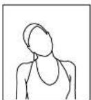
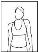
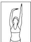
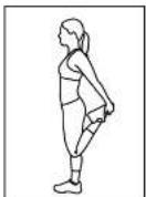
SUGGESTED STRETCHES
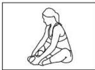
INNER THIGH STRETCH
Sit with the soles of your feet together with your knees pointing outward. Pull your feet as close into your groin as possible. Gently push your knees towards the floor. Hold for 15 counts.
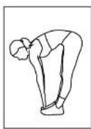
TOE TOUCHES
Slowly bend forward from your waist, letting your back and shoulders relax as you stretch toward your toes. Reach down as far as you can and hold for 15 counts.
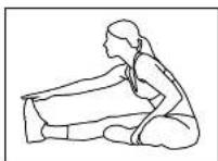
HAMSTRING STRETCHES
Sit with your right leg extended. Rest the soles of your left foot against your right Inner thigh. Stretch toward your toes as far as possible. Hold for 15 counts. Relax and then repeat with left leg extended.
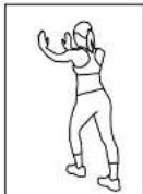
CALF/ACHILLES STRETCHES
Lean against a wall with your right leg in front of the left and your arms forward. Keep your left leg straight and the right foot on the floor; then bend the right leg and lean forward by moving your hip toward the wall. Hold, then repeat on the other side for 15 counts.
ASSEMBLY INSTRUCTIONS ASSEMBLY INSTRUCTIONS
natural_image
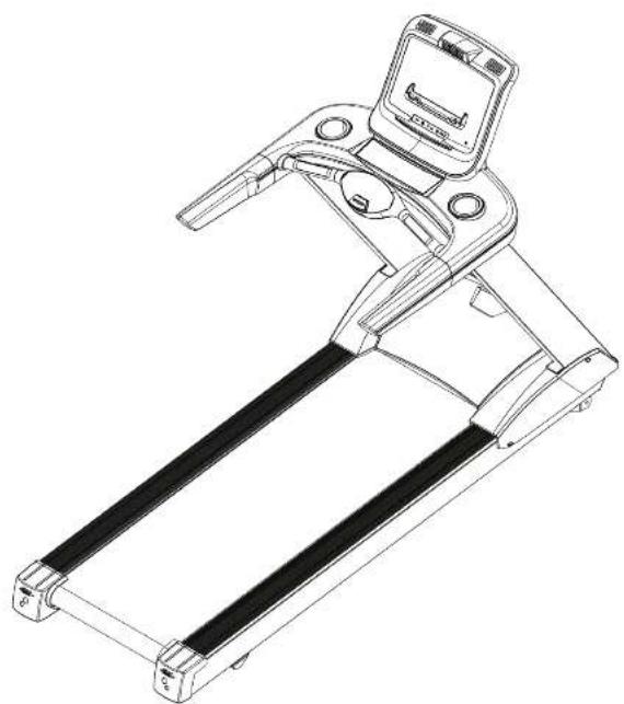
Line drawing of a treadmill with handle and control panel (no text or symbols)The assembly of this product requires two or more people. When assembling the uprights, one person should hold the uprights to prevent them from falling.
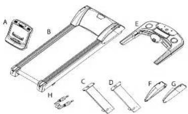
ASSEMBLY CHECKLIST
| ITEM Description Qty | |
| A Computer Console 1 | |
| B Frame 1 | |
| C Left Upright 1 | |
| D Right Upright 1 | |
| E Lower Console Structure | 1 |
| F Left Motor Lateral Cover | 1 |
| G Right Motor Lateral Cover | 1 |
| H MP3 Cable 1 |
text_image
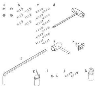
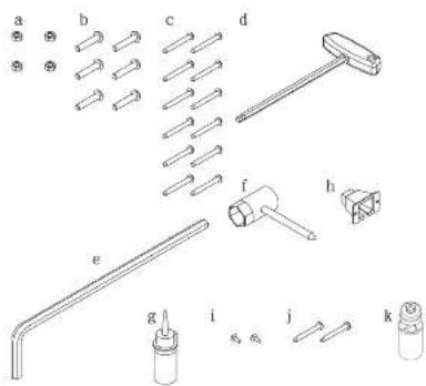
Technical diagram of a mechanical assembly with labeled parts A through G, showing exploded and assembled views.| ITEM | Description | Qty | |
| a | Nylon Nut M8xP1.25 | 4 | |
| b | Truss Phillips Screw M5xP0.8x15 | 6 | |
| c | Truss Hox Screw (Ø13) | 12 | |
| d | T-shaped Wrench 8mmx200mm | 1 | |
| e | L-shaped Hex Wrench 5mmx30mmx120mm | 1 | |
| f | Bushing Spanner + Screwdriver (13mm) | 1 | |
| g | Bottled Silicon DC-1000 | 1 | |
| h | Power Cord Switch Cover | 1 | |
| i | Truss Phillips Screw M4xP0.7x10 | 2 | |
| j | Knockdown Truss Hox Screw (Ø13) M8xP1.25x90 | 2 | |
| k | Bottle | 1 |
text_image
a b c d e f b g i j kASSEMBLY INSTRUCTIONS ASSEMBLY INSTRUCTIONS
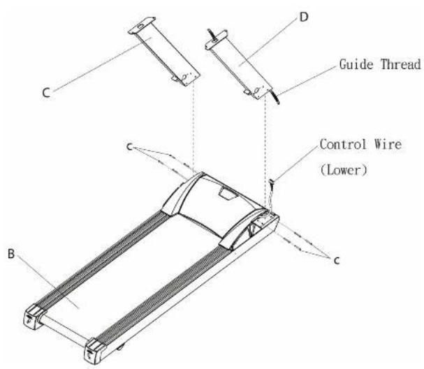
STEP 1
Attach the Left Upright (C) onto Frame (B). Then attach the control wire (located on the right of the motor shroud) to the guide wire coming out of the bottom of the Right Upright (D). Then pull the guide wire (that is attached to the control wire) through the Right upright (D) and out the top with the control wire. Be careful not to damage the wires. Then attach the Right Upright (D) to the Frame (B).
text_image
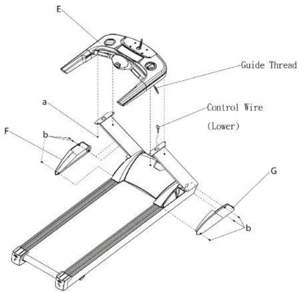
Guide Thread Control Wire (Lower) C D B CSTEP 2 (This step will require two people)
Place the Lower Console Structure (E) above the Left & Right uprights (C,D). Attach the control wire sticking out of the Right Upright (D) to the guide wire located on the bottom right of the lower console structure. Then pull the control wire through the lower console structure with the guide wire. Then attach the Lower Console Structure (E) to the Left & Right Uprights (C,D) with the Nylon Nut (a) and tighten the Screws (c). Attach the Left & Right Motor Lateral Covers (F,G) with Screws (b), tighten securely.
text_image
Guide Thread Control Wire (Lower) a b F G bRegister your product warranty online at: www.BHFitnessUSA.com
Questions regarding warranty and parts call: 636.634.2217
BH
BH
Register your product warranty online at: www.BHFitnessUSA.com
Questions regarding warranty and parts call: 636.634.2217
ASSEMBLY INSTRUCTIONS ASSEMBLY INSTRUCTIONS
STEP 3 (This step will require two people)
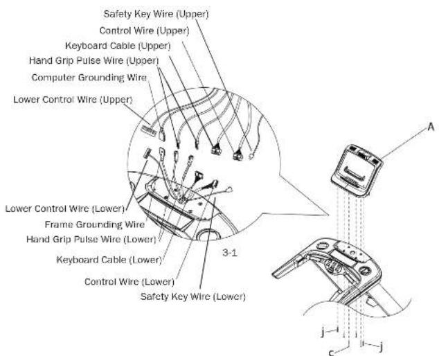
Put the Console (A) above the Lower Console Structure (E) and connect the wires as shown in the figure below. Then attached the Console (A) to the Lower Console Structure (E) with Screws (C,J). Be careful not to damage the wires. Note: The control wire has a red mark.
text_image
Safety Key Wire (Upper) Control Wire (Upper) Keyboard Cable (Upper) Hand Grip Pulse Wire (Upper) Computer Grounding Wire Lower Control Wire (Upper) Lower Control Wire (Lower) Frame Grounding Wire Hand Grip Pulse Wire (Lower) Keyboard Cable (Lower) Control Wire (Lower) Safety Key Wire (Lower) 3-1 A j c j jSTEP 4
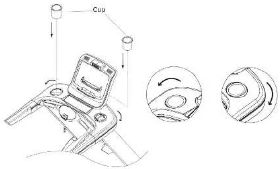
Place the cup holders on the Lower Console Structure (E) and tighten by turning the left cup counter clockwise and the right cup clockwise (as shown in image below).
text_image
CupSTEP 5
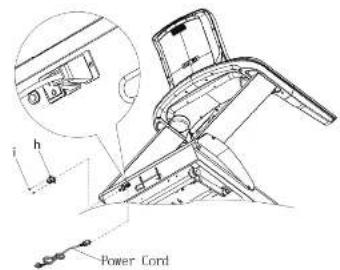
Remove the power cord and insert it into the machine, then place the Power Cord Switch Cover (h) onto the machine and tighten with Screws (i).
text_image
h Power CordASSEMBLY INSTRUCTIONS
BELT ADJUSTMENTS
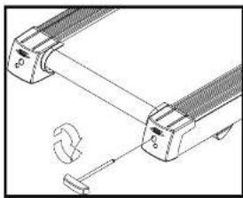
To adjust the running belt, stop the treadmill, then use the Hex Wrench and adjust the Hex Screw located in the Rear End Cap. If the running belt is moving towards the left side, tighten the left Hex Screw about 1/4 turn (clockwise); if the running belt is moving towards the right side, tighten the right Hex Screw about 1/4 turn (clockwise); Turn the treadmill on after it has been adjusted. If you find that the belt has not moved to the proper position, please repeat the steps above. Don't use the treadmill until the running belt returns to the center position.
The position of running belt might not stay precisely in the center, it can and will shift slightly towards the left and right sides, however, you do not need to adjust the belt if it is not rubbing against the side rails.
Depending on the usage of the product, please apply silicon according to the chart to the right. Use the Hex Wrench to unscrew the bolt inside the Rear Roller. Then pull the belt up and put some silicon to the center of the board. After that, adjust the belt to the center of the deck, followed by tightening the screw to the original set.
When the belt is sliding, please follow the above method to lubricate the running board.
natural_image
Technical line drawing of a mechanical device with no visible text or symbols
natural_image
Diagram of a mechanical assembly with two components and a tool, no visible text or symbolsSilicon Chart
| KGS/LBS Speed Interval | |
| KGS | 6KM/hr Below 1 year |
| 6-12KM/hr 6 months | |
| 12KM/hr Above 3 months | |
| LBS | 4 mile/hr Below 1 year |
| 4-Single/hr 6 months | |
| 8 mile/hr Above 3 months | |
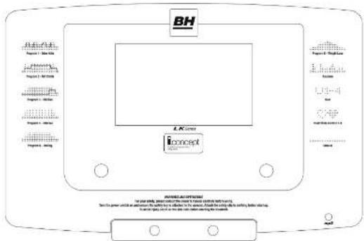
CONSOLE OPERATIONS
text_image
BH LK Screen Iconext POWER-AUTRIGER For your power, you will not have any other power to be used. Set the power unit as an antenna for the safety and safety system. Include the safety and safety warning. To ensure it is not to use any other security or the security.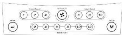
text_image
Insert Speed 1 2 4 Speed Limit 6 8 10 2 4 6 8 10 12 M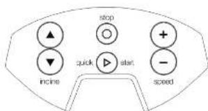
text_image
stop + quick start incine speed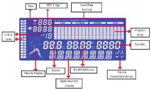
text_image
Time HFC & Age Heart Rate Training INDA Level 8:00 8:00 19 8:00 8:00 8:00 8:00 8:00 8:00 8:00 8:00 8:00 8:00 8:00 8:00 8:00 8:00 8:00 8:00 8:00 8:00 8:00 8:00 8:05 8:05 8:05 8:05 8:05 8:05 8:05 8:05 8:05 8:05 8:05 8:05 8:05 8:05 8:05 8:05 8:05 8:05 8:05 8:05 8:06 8:06 8:06 8:06 8:06 8:06 8:06 8:06 8:06 8:06 8:06 8:06 8:06 8:06 8:06 8:06 8:06 8:06 8:06 8:06 8:07 8:07 8:07 8:07 8:07 8:07 8:07 8:07 8:07 8:07 8:07 8:07 8:07 8:07 8:07 8:07 8:07 8:07 8:07 8:07 8:08 8:08 8:08 8:08 8:08 8:08 8:08 8:08 8:08 8:08 8:08 8:08 8:08 8:08 8:08 8:08 8:08 8:08 8:09 8:09 8:09 8:09 8:09 8:09 8:09 8:09 8:09 8:09 8:09 8:13ABOUT THE MUSCLE DISPLAY
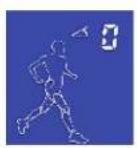
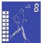
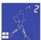
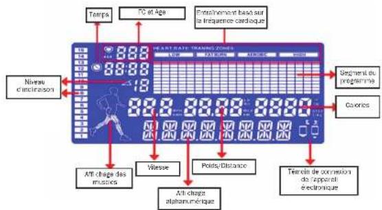
When the USER changes the incline level it will display on the screen.
Level 0
Levels 7-9
Levels 1-3
Levels 10 12
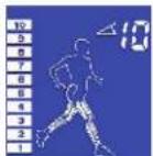
Levels 4-6
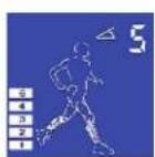
Levels 13-15
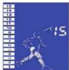
CONSOLE OPERATIONSCONSOLE OPERATIONS
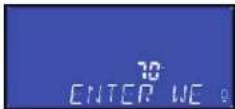
START - ENTER YOUR WEIGHT
When the machine first starts, all numerals will light up and then it will ask you to enter your weight. Set the weight, so that the each exercise program can calculate accurately how many calories have been lost during any given workout.
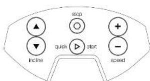
- Press SPEED+ or SPEED- to set your weight and then press ENTER to input.
- Screen will display SELECT PROGRAM.
- Press SPEED+ or SPEED- to select a program or press QUICK START to begin a manual workout immediately.
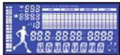
QUICK START
- Press SPEED+ or SPEED- to set your weight and then press ENTER to input.
- Press SPEED+ or SPEED- to select a program or press QUICK START to begin a manual workout immediately.
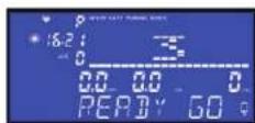
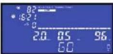
- If you select QUICK START, the screen will display READY GO and the workout will start after a 3 seconds countdown. The workout program will start at a speed of 0.8KPH (0.5MPH) and the an incline of 0.
- Press an Instant Incline button or INCLINE+ or INCLINE- to adjust the incline level
- Press an Instant Speed button or SPEED+ or SPEED- to adjust the speed value.
STOP OR PAUSE DURING TRAINING
- During the workout, press STOP to pause the program. The speed of the belt will slow to zero but the incline will stay the same.
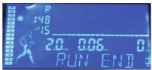
- When the workout time has reached 99:59 or you have finished the goal of a specific program, the belt will slow to zero, and the screen will display RUN END. Press STOP for 4 seconds and the systems will go back to standby mode.
Register your product warranty online at: www.BHFitnessUSA.com
Questions regarding warranty and parts call: 636.634.2217
BH
Register your product warranty online at: www.BHFitnessUSA.com
Questions regarding warranty and parts call: 636.634.2217
CONSOLE OPERATIONSCONSOLE OPERATIONS
text_image
P 48 15 20. 0.06 0 RUN ENDHOW TO SELECT A PROGRAM & PROGRAM SETUP
- Press SPEED+ or SPEED- to set your weight and then press ENTER to input.
- Press Mode or SPEED+/SPEED- to toggle through the programs, press ENTER to select.
• List: MANUAL-P1-P2-P3-P4-P5-P6-RANDOM-USER-H.R.C.1-3-BODY FAT - Pressing STOP while in any of the programs and it will bring you back to the program selection list.
- Bellow is the list of the programs and how to set up each one.
MANUAL
- Find MANUAL and press ENTER to select.
- Press SPEED+ or SPEED- to setup target time and then press ENTER to input.
- Press SPEED+ or SPEED- to setup target distance and then press ENTER to input.
- Press SPEED+ or SPEED- to setup target calories and then press ENTER to input.
- When you have finished your set up, press START to begin the workout
P1 (9 HOLE)
- Find P1 and press ENTER to select.
- Press SPEED+ or SPEED- to setup level and then press ENTER to input.
- Press SPEED+ or SPEED- to setup your goal distance and then press ENTER to input.
- The screen will display READY GO and the workout will start after a 3 seconds countdown.
P2 (HILL CLIMB)
- Find P2 and press ENTER to select.
- Press SPEED+ or SPEED- to setup the level and then press ENTER to input.
- Press SPEED+ or SPEED- to setup target time and then press ENTER to input.
- The screen will display READY GO and the workout will start after a 3 seconds countdown.
PROGRAMS P3-P6 are set up the same way as P2.
RANDOM (RANDOM SPEED)
- Find RANDOM and press ENTER to select.
- Press SPEED+ or SPEED- to select your target time and then press ENTER to input.
- Press SPEED+ or SPEED- to select target distance and then press ENTER to input.
- Press SPEED+ or SPEED- to select target calories and then press ENTER to input. 4. When you have finished your setup, press START to enter begin your workout.
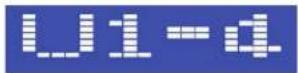
USER (USER CAN EDIT SPEED & INCLINE PROFILE)
- Find USER and press ENTER to select.
- Press SPEED+ or SPEED- to choose U1, U2, U3, or U4 and then press ENTER to select.
- Press ENTER for 3 seconds to enter into Segment Edit Mode. Press SPEED+ or SPEED- to adjust Speed and press INCLINE+ or INCLINE- to adjust incline and then press ENTER to input and go on to the next segment (there are 20 in total). When you are done with all segments, press ENTER for 3 seconds to save your custom values.
- Press ENTER to select U1.
- Press SPEED+ or SPEED- to set time and then press ENTER to input.
- Press SPEED+ or SPEED- to set distance and then press ENTER to input.
- Press SPEED+ or SPEED- to set calorie and then press ENTER to input.
- When you are done press START to begin the workout.
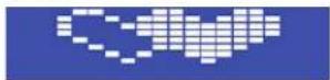
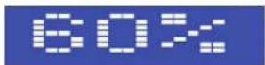
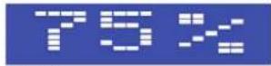
H.R.C: 60%/75%/THR
- There are three HRC programs, find and choose between 60%, 75%, or THR (Target Heart Rate) and then press ENTER to select.
Note: In the HRC Program, the computer will only accept the "Wireless Heart Rate Signal" (we suggest using a wireless heart belt). If no pulse signal is detected for 45 seconds, the computer will stop and display NO PULSE.
60%, 75%
- Press ENTER to select 60% (or 75%)
- Press SPEED+ or SPEED- to set time and then press ENTER to input.
- Press SPEED+ or SPEED- to set age and then press ENTER to input
- Press SPEED+ or SPEED- to set target heart rate and then press ENTER to input.
- The screen will display READY GO and the workout will start after a 3 seconds countdown.
THR (TARGET HEART RATE)
- Press SPEED+ or SPEED- to set target time and then press ENTER to input.
- Press SPEED+ or SPEED- to set target heart rate and then press ENTER to input.
- The screen will display READY GO and the workout will start after a 3 seconds countdown.
CONSOLE OPERATIONS
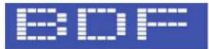
BODY FAT MODE
Press ENTER to select BODY FAT and the treadmill will ask for the following information:
-
AGE: the default value is 30, and the range 13\~80. Press SPEED+ or SPEED- to adjust and the press ENTER to input.
-
HEIGHT: the default value is 170 cm, and the range is 120\~200 cm. Press SPEED+ or SPEED- to adjust and the press ENTER to input.
-
SEX (Gender)- press SPEED+ or SPEED- to toggle between male (1) or female (0) and the press ENTER to input.
-
Weight: the default value is 70 kg (150LB) and the range is 23\~130kg (50\~425LB). Press SPEED+ or SPEED- to adjust and the press ENTER to input.
To display the BODY FAT VALUE, please hold the pulse sensors for 15 seconds. The value will display, press stop to return to the start ready status
GERKIN PROTOCOL
The Gerkin Protocol is a test used by the International Association of Fire Fighters to determine cardiovascular fi tness. This test is also regularly used to train for military fi tness tests.
Results of the test depend on the amount of time completed in the test.
I. Navigate to the Gerkin Protocol program and press ENTER. This should take you to the AGE value. Use the SPEED+ and SPEED- keys to adjust the age. The default age is 30 yrs. and the range is from 13-80 yrs. old. After choosing an age, press ENTER to confirm.
-
Gender/Sex - After pressing enter in the AGE setting, it should take you to the SEX setting. You can choose "M" for male or "F" for female by using the SPEED+ or SPEED- keys. Once you have selected a sex, press ENTER.
-
After choosing a gender, the machine will automatically go into a 3 minute warm up period. The speed of the warm up is 2.5mph (4.0 kph) and the incline is zero. All adjustments for speed and incline do not work in the warm up period.
-
After 3 minutes, the Gerkin Protocol will start. The program starts at 4.5mph (7.2 kph) and increases speed and incline throughout the program. See the chart below for the speed and incline progression.
-
In the process of the program, there is no pause. Once the STOP key is pressed at any time, the test is considered complete, and you will be judged from the stoppage point.
*NOTE - the test is 20 minutes long and will not exceed 20 minutes. After 20 minutes, the machine will automatically go into a cool down mode. The speed will reduce by half every minute until it reaches the minimum of .5mph (.8kph) and the incline goes to zero. Manual controls for speed and incline do not work during cool down.
-
When you press STOP or the cool down is finished, the machine will automatically go to the results of the test. See the charts below for ratings.
-
Note that the VO2 MAX is a Maximum Rate of Oxygen consumption during incremental exercise, and is good judge of aerobic physical fitness.
CONSOLE OPERATIONS
| Stage | Total Time Completed | Speed (km/h) | Speed (km/h) | Incine | Predicted VD2 max m/z/g/cm |
| 0 (warm-up) | 01:00 3.0 4.8 0 | 13.3 | |||
| 02:00 3.0 4.8 0 | 13.3 | ||||
| 03:00 5.0 4.8 0 | 13.3 | ||||
| 1 | 03:00 6.5 7.2 0 | 15.3 | |||
| 04:00 4.5 7.2 0 | 17.4 | ||||
| 2 | 04:00 4.5 7.2 2 | 19.4 | |||
| 05:00 6.5 7.2 2 | 21.5 | ||||
| 3 | 05:00 5.0 8.1 2 | 23.6 | |||
| 06:00 5.0 8.1 2 | 27.6 | ||||
| 4 | 06:00 5.0 8.1 4 | 28.7 | |||
| 07:00 5.0 8.1 4 | 29.8 | ||||
| 5 | 07:00 5.5 8.9 4 | 31.2 | |||
| 08:00 5.5 8.9 4 | 33.7 | ||||
| 6 | 08:00 5.5 8.9 6 | 33.9 | |||
| 09:00 5.5 8.9 6 | 35.1 | ||||
| 7 | 09:00 5.0 8.7 6 | 36.6 | |||
| 10:00 5.0 8.7 6 | 38.2 | ||||
| 8 | 10:00 5.0 8.7 8 | 39.5 | |||
| 11:00 5.0 8.7 8 | 40.9 | ||||
| 9 | 11:00 6.5 10.5 4 | 42.6 | |||
| 12:00 6.5 10.5 4 | 44.3 | ||||
| 10 | 12:00 6.5 10.5 6 | 45.7 | |||
| 13:00 6.5 10.5 6 | 47.2 | ||||
| 11 | 13:00 7.0 11.3 6 | 49.6 | |||
| 14:00 7.0 11.3 6 | 50.8 | ||||
| 12 | 14:00 7.0 11.3 2 | 52.3 | |||
| 15:00 7.0 11.3 2 | 53.6 | ||||
| 13 | 15:00 7.5 12.1 2 | 55.8 | |||
| 16:00 7.5 12.1 2 | 57.6 | ||||
| 14 | 16:00 7.5 12.1 4 | 59.5 | |||
| 17:00 7.5 12.1 4 | 61.2 |
CONSOLE OPERATIONS
| Stage | Total Time Completed | Speed (mile/h) | Speed (km/h) | Incline | Predicted VO2 max ml/kg/min |
| 15 | 17:30 8.0 12.9 14 63.2 | ||||
| 18:00 8.0 12.9 14 65.3 | |||||
| 16 | 18:30 8.0 12.9 15 67.1 | ||||
| 19:00 8.0 12.9 15 68.8 | |||||
| 17 | 19:30 8.5 13.7 15 71.1 | ||||
| 20:01 8.5 13.7 15 73.3 |
MALE: VO2 MAX (VALUES IN ML/KG/MIN)
| Age Very Poor Poor Fair Good Excellent | Superior | ||||||
| -19 | <35.0 | 35.0 - 38.3 | 38.4 - 45.1 | 45.2 - 50.9 | 51.0 - 55.9 | >55.9 | |
| 20-29 | <33.0 | 33.0 - 36.4 | 36.5 - 42.4 | 42.5 - 46.4 | 46.5 - 52.4 | >52.4 | |
| 30-39 | <31.5 | 31.5 - 35.4 | 35.5 - 40.9 | 41.0 - 44.9 | 45.0 - 49.4 | >49.4 | |
| 40-49 | <30.2 | 30.2 - 33.5 | 33.6 - 38.9 | 39.0 - 43.7 | 43.8 - 48.0 | >48.0 | |
| 50-59 | <26.1 | 26.1 - 30.9 | 31.0 - 35.7 | 35.8 - 40.9 | 41.0 - 45.3 | >45.3 | |
| 60+ | <20.5 | 20.5 - 26.0 | 26.1 - 32.2 | 32.3 - 36.4 | 38.5 - 44.2 | >44.2 | |
FEMALE: VO2 MAX (VALUES IN ML/KG/MIN)
| Age | Very Poor | Poor | Fair | Good | Excellent | Superior |
| 19 | <25.0 | 25.0 - 30.9 | 31.0 - 34.9 | 35.0 - 38.9 | 39.0 - 41.9 | >41.9 |
| 20-29 | <23.6 | 23.6 - 28.9 | 29.0 - 32.9 | 33.0 - 38.9 | 37.0 - 41.0 | >41.0 |
| 30-39 | <22.8 | 22.8 - 26.9 | 27.0 - 31.4 | 31.5 - 35.6 | 35.7 - 40.0 | >40.0 |
| 40-49 | <21.0 | 21.0 - 24.4 | 24.5 - 28.9 | 29.0 - 32.8 | 32.9 - 36.9 | >36.9 |
| 50-59 | <20.2 | 20.2 - 22.7 | 22.8 - 26.9 | 27.0 - 31.4 | 31.5 - 35.7 | >35.7 |
| 60+ | <17.5 | 17.5 - 20.1 | 20.2 - 24.4 | 24.5 - 30.2 | 30.3 - 31.4 | >31.4 |
CONSOLE OPERATIONS
MANUAL
P19 Hole
Hidden Area
P2 Hill Climb
Hidden Area
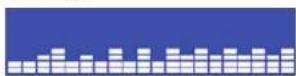
P3 Hill Run
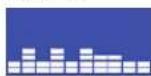
Hidden Area
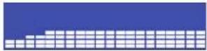
P4 Interval
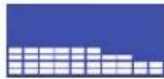
Hidden Area
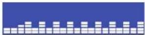
P5 Rolling
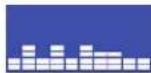
Hidden Area
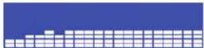
P6 Weight Loss
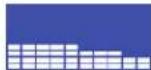
Hidden Area
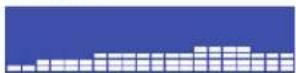
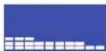
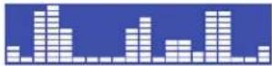
RANDOM
USER
HRC 1-3
HRC 60%
HRC 75%
HRC THR

BODY FAT (BDF)
TO SWITCH BETWEEN METRIC AND STANDARD
When the machine first starts, all numerals will light up and then it will ask you to enter your weight. While in this window, press and hold ENTER for 10 seconds. Press SPEED+ or SPEED- to toggle between ML (Standard) and KM (Metric) and then press ENTER to make your selection.
ERROR & WARNING INFORMATION
When the treadmill motor is experiencing a malfunction, machine will auto-stop and show one of the error codes listed below.
E1: Can not read the speed value, motor is malfunctioning and signal cannot be delivered.
E6: Incline data is wrong, incline motor damaged or signal cannot be delivered.
E7: Incline AD over the normal range, incline motor damaged or setting is wrong.
CONSOLE OPERATIONSCONSOLE OPERATIONS
DOWNLOADING APPS AND PAIRING YOUR DEVICE
DOWNLOADING THE SOFTWARE
Connect the Apple device with the App Store (iTunes) or your Android Device with Google Play, search for "Pafers", then read the APP introductions and Download the APPs with bicycle/elliptical machine functions to your device, for example Pedal Monitor or other applicable apps. Note: if you download an APP for a treadmill and pair it with an Elliptical it will not work.
- The App uses bluetooth mode, so please make sure the equipment and device you are using has bluetooth function.
- The App contains the following functions, the user must open the 3G network or wifi network:
(a) Managing Data - After completing the registration in the 'Pafers' App, log on to your personal account. Now that you have registered you can record all of your workout data and save it to your device.
(b) Some APPs need connection to Google maps in order to function correctly.
PAIRING THE BLUETOOTH DEVICE WITH AN APPLE DEVICE
-
Place the Apple Device on the area in front of the LCD screen.
-
Enter into settings and turn Bluetooth on.
-
Your Apple Device will detect all Bluetooth devices within range (following on screen instructions), click on the appropriate bluetooth device name and confirm your connection.
-
After paired successfully, please start the APP within 2 minutes, if you do not, Bluetooth will automatically cancel the pairing. Please keep the Apple Device within a range of 2 meters for best quality connection. If you see "not connected," please perform the above steps again.
-
Press the Apple Device home button, the screen will return to the desktop.
-
Start the APP you downloaded. When the APP connects with the equipment successfully, the APP screen buttons will unlocked. Start from APP interface using a variety of modes to control the exercise equipment. Pay attention to the APP instructions and function introduction. If you have need help with the APP, please browse the APPs download page description or contact Pafers for instructions.
-
When you are done using the APP, please press the HOME button on the Apple Device twice to close the APP.
PAIRING THE BLUETOOTH DEVICE WITH AN ANDROID DEVICE
-
Place the Android Device on the area in front of the LCD screen.
-
Enter into settings and turn Bluetooth on.
-
Your Android Device will detect all Bluetooth devices within range (following on screen instructions), click on the appropriate bluetooth device name and confirm your connection.
-
After paired successfully, please start the APP within 2 minutes, if you do not, Bluetooth

Register your product warranty online at: www.BHFitnessUSA.com
Questions regarding warranty and parts call: 636.634.2217

Register your product warranty online at: www.BHFitnessUSA.com
Questions regarding warranty and parts call: 636.634.2217
CONSOLE OPERATIONS
will automatically cancel the pairing. Please keep the Android Device within a range of 2 meters for best quality connection. If you see "not connected," please perform the above steps again.
- Press the Apple Device home button, the screen will return to the desktop.
- Start the APP you downloaded. When the APP connects with the equipment successfully, the APP screen buttons will unlocked. Start from APP interface using a variety of modes to control the exercise equipment. Pay attention to the APP instructions and function introduction. If you have need help with the APP, please browse the APPs download page description or contact Pafers for instructions.
- When you are done using the APP, please press main screen button on the Android Device twice to close the APP.
COMPATIBLE DEVICES
ANDROID
Bluetooth & App Enabled Android Device
APPLE PRODUCTS
| iPod touch (4th generation) | iPod touch (3rd generation) | ||
| iPhone | 5 | iPhone | 4S |
| iPhone | 4 | Mini | iPad |
| iPad | iPad | 2 | |
i. Concept Bluetooth products are compatible with Apple devices with iOS 5.1 or later. It is recommended to update iOS to latest version to obtain the best user experience.
iPad, iPhone, iPod, iPod classic, iPod nano, iPod shuffle, and iPod touch, is a registered trademark of Apple, Inc., in the United States and other countries.
"Made for iPod," "Made for iPhone," and "Made for iPad" mean that an electronic accessory has been designed to connect specifically to iPod, iPhone, or iPad, respectively, and has been certified by the developer to meet Apple performance standards. Apple is not responsible for the operation of this device or its compliance with safety and regulatory standards. Please note that the use of this accessorywith iPod, iPhone, or iPad may affect wireless performance. iPad, iPhone, iPod, iPod classic, iPod nano, iPod shuffle, and iPod touch are trademarks of Apple Inc., registered in the U.S. and other countries.
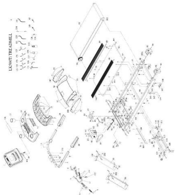
EXPLODED VIEW
text_image
LK500T TREADMILL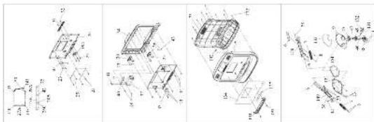
text_image
Technical diagram showing four views of a mechanical assembly with labeled components and cross-sectional views.PARTS LIST
To order replacement parts; provide your customer service representative with the product model number and the part number located on the Parts List below, along with the quantity you require.
| No. | Description Qty/ No. | Description Qty/ No. | Description Qty | |||||
| LXSC07 1 | Compulsia assembly | 5 | LXSC07 66 | Plastic | 1 | LXSC07 115 | Outer hand hat sleeve | |
| LXSC07 13 | Kit | 14 | LXSC07 81 | Disk heat sensors | 4 | LXSC07 120 | Outer sheathing | |
| LXSC07 16 | Coarse frame | 1 | LXSC07 62 | Hot water | 5 | LXSC07 123 | Bermel seat (balance) | |
| LXSC07 16 | Hand pump plastic seat (top) | 2 | LXSC07 624 | Flat water | 1 | LXSC07 125 | Bermel seat (brushes) | |
| LXSC07 17 | Hand pump pipe water and power | 3 | LXSC07 63 | Spring water | 4 | LXSC07 126 | Bermel seat (yellow and green) | |
| LXSC07 18 | Philips screw | 4 | LXSC07 63 | Jet | 1 | LXSC07 129 | Outer wheel key socket | |
| LXSC07 19 | On hot disc cooling | 1 | LXSC07 65 | DLS heat sensors | 1 | LXSC07 137 | HFD socket | |
| LXSC07 11 | Philips screw | 4 | LXSC07 66 | Air vent | 1 | LXSC07 129 | Outer wheel mounting base | |
| LXSC07 12 | Carton box cover (bottom) | 1 | LXSC07 67 | Wiring head buttons | 2 | LXSC07 129 | Zip file | |
| LXSC07 13 | Philips screw | 6 | LXSC07 68 | PHSs screw | 5 | LXSC07 130 | Right side | |
| LXSC07 14 | Shaft cover (top) | 2 | LXSC07 69 | Wiring two buttons | 1 | LXSC07 131 | Rear | |
| LXSC07 15 | Shell rotor (bottom) | 1 | LXSC07 70 | Press screw | 4 | LXSC07 133 | Clip | |
| LXSC07 16 | Philips screw | 47 | LXSC07 71 | Power wire select. | 1 | LXSC07 138 | Left one control box screws | |
| LXSC07 17 | Rotor bottle | 2 | LXSC07 72 | Power switch | 1 | LXSC07 138 | Flaming box | |
| LXSC07 18 | Inscute (bottom) | 1 | LXSC07 73 | Power wire | 1 | LXSC07 134 | Computer seats | |
| LXSC07 19 | Inscute right | 2 | LXSC07 74 | Power one switch sets | 1 | LXSC07 135 | Tobacco seats | |
| LXSC07 22 | Power ring F20 plane 1 | LXSC07 75 | Computer door lock | 1 | LXSC07 136 | Computer handlepin switches 1 | ||
| LXSC07 23 | Rotor screw | 47 | LXSC07 75 | Computer door static | 1 | LXSC07 137 | Sweat camera seat | |
| LXSC07 25 | Computer | 1 | LXSC07 75 | Sweat press protection buttons | 1 | LXSC07 138 | Sheet | |
| LXSC07 28 | Compulsia strict line | 5 | LXSC07 77 | Power wire end | 1 | LXSC07 140 | Candle down steps | |
| LXSC07 27A | Solve switch connected wire (top) | 1 | LXSC07 78 | Pulce set | 1 | LXSC07 141 | Hand valve wire top | |
| LXSC07 27B | Solve switch connected wire (bottom) | 1 | LXSC07 78 | PHSs screw | 4 | LXSC07 143 | Heat screws | |
| LXSC07 28A | Press key connected wire (top) | 1 | LXSC07 80 | Sensor fixed seat | 1 | LXSC07 144 | Washer | |
| LXSC07 28B | Press key connected wire (bottom) | 1 | LXSC07 81 | Sweat slot | 1 | LXSC07 145 | Spinal washer | |
| LXSC07 29C | Press key connected wire (bottom) | 1 | LXSC07 82 | Power hubers | 6 | LXSC07 146 | Motor side row dialing | |
| LXSC07 30 | Hand pulse pad | 1 | LXSC07 83 | Rushing board | 2 | LXSC07 147 | Motor side row dialing | |
| LXSC07 30C | Foam stopper | 1 | LXSC07 84 | PHSs screw | 1 | LXSC07 148 | Zip kit | |
| LXSC07 31 | Mid plane or seat | 1 | LXSC07 85 | Up line | 1 | LXSC07 149 | Heating one side holding | |
| LXSC07 32 | DRS two arms | 2 | LXSC07 86 | Up screen | 6 | LXSC07 150 | Heating one plane (top) | |
| LXSC07 33 | Audio source plane | 1 | LXSC07 87 | Hot screw | 4 | LXSC07 150 | Heating one plane (right) | |
| LXSC07 34 | Compulsia screw | 1 | LXSC07 88 | Aluminum pedal | 2 | LXSC07 152 | Heating one plane (right) | |
| LXSC07 35 | Carton mode (top) | 1 | LXSC07 89 | Zoom screw | 2 | LXSC07 153 | Front box rear walking | |
| LXSC07 36 | Speaker | 2 | LXSC07 90 | Aluminum pedal stopper | 8 | LXSC07 152 | Insert box screw | |
| LXSC07 37 | Press flow fin | 1 | LXSC07 92 | Sweat adjusting on left | 1 | LXSC07 155 | Votor box |
PARTS LIST
To order replacement parts: provide your customer service representative with the product model number and the part number located on the Parts List below, along with the quantity you require.
| LX500T-38 | Hand, use wire (box) | 2 | LX500T-95 | Lower adjusting wire gift | 1 | LX500T-154 | MPS wire cable | 1 | ||
| LX500T-39 | Trip rope | 15 | LX500T-04 | Pilot hose | 2 | LX500T-163A | Controller | 1 | ||
| LX500T-70 | Fire stopper | 1 | LX500T-96 | Flying belt | 1 | LX500T-154 | Hand on the grunting line lower yellow and green | 1 | ||
| LX500T-41 | Trip rope | 4 | LX500T-96 | Port pulley | 1 | LX500T-172 | Trip rope | 12 | ||
| LX500T-42 | Cartoon, blade connected arm | 1 | LX500T-97 | CRS box sleeve | 1 | LX500T-172 | Air cushion matching box | 7 | ||
| Work case mechanical head/lead | 1 | LX500T-89 | Lock washer | 1 | LX500T-175 | Box washer | 2 | |||
| Pilot receive | 1 | LX500T-100 | Hot nut | 1 | LX500T-177 | Terminal wire yellow and green | 1 | |||
| LX500T-43 | Double Diameter Tape | 1 | LX500T-101 | Terminal wire gait low and pretty | 1 | LX500T-178 | Terminal wire printer | 1 | ||
| LX500T-44 | Trip rope | 10 | LX500T-102 | Roof s Hockey | 1 | LX500T-179 | Terminal wire (clock) | 1 | ||
| LX500T-45 | Back view switch button | 1 | LX500T-103A | CRS box sleeve | 2 | LX500T-184 | Ground confirmation socket | 2 | ||
| LX500T-46 | Carry side switch burner | 1 | LX500T-104 | Hard cord plate | 1 | LX500T-185 | Ground confirmation socket | 3 | ||
| LX500T-47 | Tweerle spring | 1 | LX500T-105 | Softening shee | 4 | LX500T-187 | Trip rope | 1 | ||
| LX500T-48 | Safety switch base | 1 | LX500T-107 | Bucket foot rod | 2 | LX500T-189 | Hot plugs | 4 | ||
| LX500T-49 | Carry side switch at the end | 1 | LX500T-108 | Bucket screw | 4 | LX500T-190 | Bucket pin | 2 | ||
| LX500T-50 | Spring ring | 1 | LX500T-109 | Rod tube | 1 | LX500T-192 | Pod sink | 1 | ||
| LX500T-51 | Spring light | 1 | LX500T-110 | Fixed base | 2 | LX500T-192 | Extension nut | 2 | ||
| LX500T-52 | Hot seconds | 12 | LX500T-111 | CRS box sleeve | 4 | LX500T-193 | Pull pump rope | 2 | ||
| LX500T-53 | Line receiver | 4 | LX500T-112 | Spindle wheel | 2 | LX500T-194 | Pusher module | 1 | ||
| LX500T-54 | Motor cover | 1 | LX500T-113 | Holder wheel | 2 | |||||
| LX500T-55 | Trip rope | 13 | LX500T-114 | CRS box sleeve | 2 | |||||
| LX500T-56 | Deck sweater | 2 | LX500T-115 | Circular blade hit | 2 | |||||
| LX500T-57 | Back view motor | 1 | LX500T-116 | R/meg | 2 | |||||
| LX500T-58 | Close fix screw | 1 | LX500T-117 | Rect pad | 2 | |||||
| LX500T-59 | Nut | 3 | LX500T-118 | Washer | 2 | |||||
| LX500T-60 | Nut | 1 |
Register your product warranty online at: www.BHFitnessUSA.com Questions regarding warranty and parts call: 636.634.2217
BH
BH
Register your product warranty online at: www.BHFitnessUSA.com Questions regarding warranty and parts call: 636.634.2217
WARRANTY
COMMERCIAL WARRANTY\*
BH North America will repair or replace, free of charge, at its option, parts that are defective as a result of material or workmanship. Lifetime replacement warranty coverage on frame and fi ve (5) years on motor and other parts. Labor warranty coverage is two (2) years. Warranty covers the original consumer purchaser only.
*Commercial Warranty Disclaimer: For non-dues paying facilities, with less than 8 hours of use per day.
LIMITED RESIDENTIAL WARRANTY
BH North America will repair or replace, free of charge, at its option, parts that are defective as a result of material or workmanship. Lifetime replacement warranty coverage on frame and ten (10) years on other parts. Labor warranty coverage is two (2) years. Warranty covers the original consumer purchaser only.
COSMETICS PARTS DISCLAIMER
For all products and all level of warranty, cosmetic parts shall be warranted for 1 year from date of purchase against manufactures defect. "Cosmetics" includes: External plastics, overlays/decals and covers.
THIS WARRANTY DOES NOT COVER
- Pre-delivery set-up.
- Components that require replacement due to dirt or lack of regular maintenance.
- Repairs necessary because of operator abuse or negligence or the failure to operate and maintain the equipment according to the Instructions contained in the Owner's Manual.
FOR WARRANTY REPAIRS, PLEASE DO NOT TAKE YOUR MACHINE BACK TO THE RETAIL STORE. CONTACT BH FITNESS FIRST.
BH North America Corporation
620 N. 2nd Street | St. Charles, MO 63301
Phone:636-487-0050; Toll Free: 866.325.2339
Web: www.BHFITNESSUSA.COM
Mon - Fri 8am - 5pm CST
Register your product warranty online at: www.BHFitnessUSA.com
Questions regarding warranty and parts call: 636.634.2217

BH
LK500Ti
GUIDE D'UTILISATION
natural_image
Technical line drawing of a treadmill device with handle and frame (no text or symbols)BH FITNESS | 620 N. 2nd Street, St. Charles, MO 63301
p.636-487-0050 | www.BHFitnessUSA.com | www.BHFitnessCanada.ca

TABLE DES MATIÈRES
Titre Page
Toutes Nos Félicitations .... 36
Entretien Et Nettoyage 36
natural_image
Line drawing of a treadmill with control panel and adjustable arm (no text or symbols)text_image
Technical diagram of a mechanical assembly with labeled parts A through G, showing exploded and assembled views.| PRODUIT Descriptio 396 | ||
| a | Cronu en myon MSRP1.25 | 4 |
| b | Vis Truss MSRP0.8x12 | 6 |
| c | Vis Truss & six pens (8x13) | 12 |
| d | Clé en forme do T 8mmx200mm | 1 |
| e | Clé hexagonale en L 5mmx30mmx-120mm | 1 |
| f | Clé pour baguc + Tournevis (15mm) | 1 |
| g | Sillicum conditionna DC-1000 | 1 |
| h | Sillicum conditionna DC-1000 | 1 |
| i | Vis Truss M4xPD 7x10 | 2 |
| j | Vis Truss hexagonale à enhancer (L13) MSRP1. 25x90 | 2 |
text_image
Technical diagram showing labeled mechanical components and assembly parts, including rods, gears, and a tool.INSTRUCTIONS D'ASSEMBLAGE INSTRUCTIONS D'ASSEMBLAGE
ÉTAPE 1
text_image
Technical diagram showing mechanical assembly with labeled components and directional arrows indicating rotation or movement.ÉTAPE 5
natural_image
Technical line drawing of a mechanical device with no visible text or symbols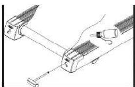
natural_image
Diagram of a mechanical assembly with two components and a tool, no visible text or symbolsTableau silicone
text_image
BH L.R. Cross Concept PHYSICAL INFORMATION For your body, please contact the device's front panel with the following: WITH THE POWER OF THE CONCEPT TO BE USED IN THE POWER OF THE CONCEPT TO BE USED IN THIS Panel (1). Please contact the device on the front panel.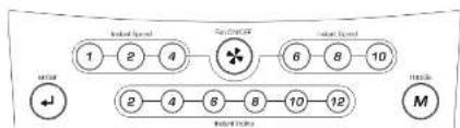
flowchart
graph TD
    A["1"] --> B["2"]
    B --> C["4"]
    C --> D["5"]
    D --> E["6"]
    E --> F["8"]
    F --> G["10"]
    G --> H["M"]
    I["Start"] --> J["2"]
    J --> K["4"]
    K --> L["6"]
    L --> M["8"]
    M --> N["10"]
    N --> O["12"]
    O --> P["End"]
text_image
stop ↑ ○ + ▼ quick start -FONCTIONNEMENT DE LA CONSOLE FONCTIONNEMENT DE LA CONSOLE
H.R.C (FC): 60%/75%/THR (FRÉQUENCE CARDIAQUE CIBLE)
text_image
LIX5001 TREADMILL D: 12.0 13.0 14.0 15.0 16.0 17.0 18.0 19.0 20.0 21.0 22.0 23.0 24.0 25.0 26.0 27.0 28.0 29.0 30.0 31.0 32.0 33.0 34.0 35.0 36.0 37.0 38.0 39.0 40.0 41.0 42.0 43.0 44.0 45.0 46.0 47.0 48.0 49.0 50.0 51.0 52.0 53.0 54.0 55.0 56.0 57.0 58.0 59.0 60.0 61.0 62.0 63.0 64.0 65.0 66.0 67.0 68.0 69.0 70.0 71.0 72.0 73.0 74.0 75.0 76.0 77.0 78.0 79.0 80.0 81.0 82.0 83.0 84.0 85.0 86.0 87.0 88.0 89.0 90.0 91.0 92.0 93.0 94.0 95.0 96.0 97.0 98.0 99.0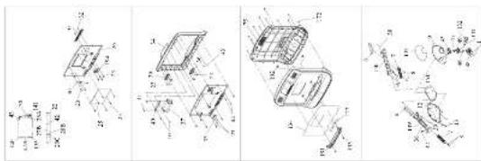
text_image
Technical diagram showing four views of a mechanical assembly with labeled components and assembly details[Non-Text]
[Non-Text]
BH
LISTE DES PIÈCES
BH North America Corporation
620 N. 2nd Street | St. Charles, MO 63301
Phone:636-487-0050; Toll Free: 866.325.2339
Courriel : fitness@bhnorthamerica.com
Web : www.BHFITNESSUSA.COM