
AquaLink RS All Button - Electronic control system Jandy - Free user manual and instructions
Find the device manual for free AquaLink RS All Button Jandy in PDF.
| Product Type | Electronic control system for swimming pool and spa |
| Brand | JANDY |
| Model | AquaLink RS All Button |
| Power Supply | 120 V AC, 60 Hz, 3 A |
| Maximum high voltage contact power | 25 A, 3 HP @240 V AC / 1.5 HP @120 V AC |
| Low Voltage | Class 2, 1 A at 24 V AC |
| Number of Relays | Up to 8 high voltage relays (depending on configuration) |
| Main Functions | Control of filtration, heating, pumps, lighting, push button valves, heat pump, solar, iAquaLink |
| Control Panel | OneTouch (indoor) with LCD screen and buttons |
| Connectivity | iAquaLink Web-Connect (WiFi or Ethernet) |
| Temperature Sensors | Water, air and solar (optional) |
| Protection | Ground Fault Circuit Interrupter (GFCI) required |
| Standards | UL STD 1563, CSA C22.2 No. 218.1, FCC Class B |
| Dimensions (approximate) | 30 x 25 x 15 cm |
| Weight (approximate) | 2.5 kg |
| Operating Temperature | 0 °C to 50 °C (estimate) |
| Warranty | Consult the manual or dealer |
Frequently Asked Questions - AquaLink RS All Button Jandy
User questions about AquaLink RS All Button Jandy
0 question about this device. Answer the ones you know or ask your own.
Ask a new question about this device
Download the instructions for your Electronic control system in PDF format for free! Find your manual AquaLink RS All Button - Jandy and take your electronic device back in hand. On this page are published all the documents necessary for the use of your device. AquaLink RS All Button by Jandy.
USER MANUAL AquaLink RS All Button Jandy
AquaLink® RS Control Systems
For use with Pool/Spa Combination, Pool Only/Spa Only, and Dual Equipment AquaLink RS Systems with Rev Y Firmware
WARNING
FOR YOUR SAFETY – This product must be installed and serviced by a contractor who is licensed and qualified in pool equipment by the jurisdiction in which the product will be installed where such state or local requirements exist. The maintainer must be a professional with sufficient experience in pool equipment installation and maintenance so that all of the instructions in this manual can be followed exactly. Before installing this product, read and follow all warning notices and instructions that accompany this product. Failure to follow warning notices and instructions may result in property damage, personal injury, or death. Improper installation and/or operation may void the warranty. DO NOT MODIFY THIS EQUIPMENT.

Improper installation and/or operation can create unwanted electrical hazard which may cause serious injury, property damage, or death.
ATTENTION INSTALLER – This manual contains important information about the installation, operation and safe use of this product. This information should be given to the owner/operator of this equipment.
Table of Contents
Section 1. Important Safety Instructions .....3
1.1 Safety Instructions ....3
Section 2. System Overview ...... 5
2.1 System Component Specifications and Dimensions....5
2.2 Basic Plumbing 6
Section 3. Installation....8
3.1 Power Center Mounting 8
3.2 High Voltage Wiring....8
3.3 Low Voltage Wiring 13
3.4 Heater Connection....16
3.5 Temperature Sensors ....18
3.6 Jandy Valve ^® Actuators....18
3.7 Jandy TruSense Water Chemistry Analyzer....18
3.8 Auxiliary Power Centers....19
3.9 OneTouch Control Panel Indoor Installation....19
3.10 iAquaLink Web-Connected Device Installation....21
3.11 Powered Hardware Connection Test:......24
3.12 Further Reference Information .....24
Section 4. Troubleshooting....25
4.1 OneTouch Quick Troubleshooting Guide .....25
4.2 iAquaLink Troubleshooting Guide .....26
4.3 LED Status Indicator Lights 27
Section 5. Power Center Wiring Diagram for Combos and Onlys .....28
Section 6. Power Center PCB DIP Switch Settings....29
6.1 DIP Switch Functions....29
6.2 DIP Switch Settings for Pool and Spa Combination....30
6.3 DIP Switch Settings for Pool or Spa Only....31
6.4 DIP Switch Settings for Heat Pump Installation....32
EQUIPMENT INFORMATION RECORD
DATE OF INSTALLATION
INSTALLER INFORMATION
INITIAL PRESSURE GAUGE READING (WITH CLEAR FILTER)
PUMP MODEL
HORSEPOWER
NOTES
Section 1. Important Safety Instructions
READ AND FOLLOW ALL INSTRUCTIONS
1.1 Safety Instructions
All electrical work must be performed by a licensed electrician and conform to all national, state, and local codes. When installing and using this electrical equipment, basic safety precautions should always be followed, including the following:
WARNING
To reduce the risk of severe injury or death, do not remove the suction fittings of your spa or hot tub. Never operate a spa or hot tub if the suction fittings are broken or missing. Never replace a suction fitting with one rated less than the flow rate marked on the equipment assembly.
WARNING
Prolonged immersion in hot water may induce hyperthermia. Hyperthermia occurs when the internal temperature of the body reaches a level several degrees above the normal body temperature of 98.6^ F ( 37^ C). The symptoms of hyperthermia include dizziness, fainting, drowsiness, lethargy, and an increase in the internal temperature of the body. The effects of hyperthermia include: 1) unawareness of impending danger; 2) failure to perceive heat; 3) failure to recognize the need to exit spa; 4) physical inability to exit spa; 5) fetal damage in pregnant women; 6) unconsciousness resulting in a danger of drowning; 7) The use of alcohol, drugs, or medication can greatly increase the risk of fatal hyperthermia in hot tubs and spas. less than the flow rate marked on the equipment assembly.
WARNING
To Reduce the Risk of Injury -
- The water in a spa should never exceed 104°F (40°C). Water temperatures between 100°F (38°C) and 104°F (40°C) are considered safe for a healthy adult. Lower water temperatures are recommended for young children and when spa use exceeds 10 minutes.
- Since excessive water temperatures have a high potential for causing fetal damage during the early months of pregnancy, pregnant or possibly pregnant women should limit spa water temperatures to 100^ F ( 38^ C).
- Before entering a spa or hot tub, the user should measure the water temperature with an accurate thermometer since the tolerance of water temperature-regulating devices varies.
- The use of alcohol, drugs, or medication before or during spa or hot tub use may lead to unconsciousness with the possibility of drowning.
- Obese persons and persons with a history of heart disease, low or high blood pressure, circulatory system problems, or diabetes should consult a physician before using a spa.
- Persons using medication should consult a physician before using a spa or hot tub since some medication may induce drowsiness while other medication may affect heart rate, blood pressure, and circulation.
WARNING
Risk of electric shock, which could result in severe injury or death - Install the power center at least five (5) feet (1.52m) from the inside wall of the pool and/or hot tub using non-metallic plumbing. Canadian, Australian, and European installations must be at least three (3) meters from the water.
Children should not use spas or hot tubs without adult supervision.
Do not use spas or hot tubs unless all suction guards are installed to prevent body and hair entrapment.
People using medications and/or having an adverse medical history should consult a physician before using a spa or hot tub.
WARNING
People with infectious diseases should not use a spa or hot tub.
To avoid injury, exercise care when entering or exiting the spa or hot tub.
Do not use drugs or alcohol before or during the use of a spa or hot tub to avoid unconsciousness and possible drowning.
Do not use a spa or hot tub immediately following strenuous exercise.
Prolonged immersion in a spa or hot tub may be injurious to your health.
Do not permit any electric appliance (such as a light, telephone, radio, or television) within 5 feet (1.52m) of a spa or hot tub.
The use of alcohol, drugs or medication can greatly increase the risk of fatal hyperthermia in hot tubs and spas.
WARNING
To avoid injury ensure that you use this control system to control only packaged pool/spa heaters which have built-in operating and high limit controls to limit water temperature for pool/spa applications. This device should not be relied upon as a safety limit control. Water temperature in excess of 100^ F ( 38^ C) may be hazardous to your health.
WARNING
A terminal bar marked “GROUND” is provided within the power center. To reduce the risk of electrical shock, connect this terminal bar to the grounding terminal of your electric service or supply panel with a continuous copper conductor having green insulation and one that is equivalent in size to the circuit conductors supplying this equipment, but no smaller than no. 12 AWG (3.3mm2). In addition, a second wire connector should be bonded with a no. 8 AWG (8.4mm2) copper wire to any metal ladders, water pipes, or other metal within five (5) feet (1.52m) of the pool/spa. In Canada, the bonding wire must be minimum 6 AWG (13,3mm2).
WARNING
A ground-fault circuit-interrupter must be provided if this device is used to control underwater lighting fixtures. The conductors on the load side of the ground-fault circuit-interrupter shall not occupy conduit, boxes, or enclosures containing other conductors unless the additional conductors are also protected by a ground-fault circuit-interrupter. Refer to local codes for complete details.

Attention installer: Install to provide drainage of compartment for electrical components.
FCC Regulatory Compliance Statement
This device complies with Part 15 of the FCC Rules. Operation is subject to the following two conditions:
- This device may not cause harmful interference, and
- This device must accept any interference received, including interference that may cause undesired operation.
CAUTION: Changes or modifications not expressly approved by the party responsible for compliance could void the user's authority to operate the equipment.
NOTE: This equipment has been tested and found to comply with the limits for a Class B digital device, pursuant to Part 15 of the FCC Rules. These limits are designed to provide reasonable protection against harmful interference in a residential installation. This equipment generates, uses and can radiate radio frequency energy and, if not installed and used in accordance with the instructions, may cause harmful interference to radio communications. However, there is no guarantee that interference will not occur in a particular installation. If this equipment does cause harmful interference to radio or television reception, which can be determined by turning the equipment off and on, the user is encouraged to try to correct the interference by one or more of the following measures:
- Reorient or relocate the receiving antenna.
- Increase the separation between the equipment and receiver.
- Connect the equipment into an outlet on a circuit different from that to which the receiver is connected.
- Consult the dealer or an experienced radio/TV technician for help.
SAVE THESE INSTRUCTIONS
Section 2. System Overview
2.1 System Component Specifications and Dimensions
Specifications (USA and Canada)
Power Supply 120 VAC; 60 Hz; 3 A
Contact Rating High voltage - 25 A; 3HP @ 240 VAC
1½ HP @120 VAC
1500 Watts Incandescent
Low Voltage - Class 2, 1 A @ 24 VAC
Service Switch All Circuits (located at Power Center in Service Mode)
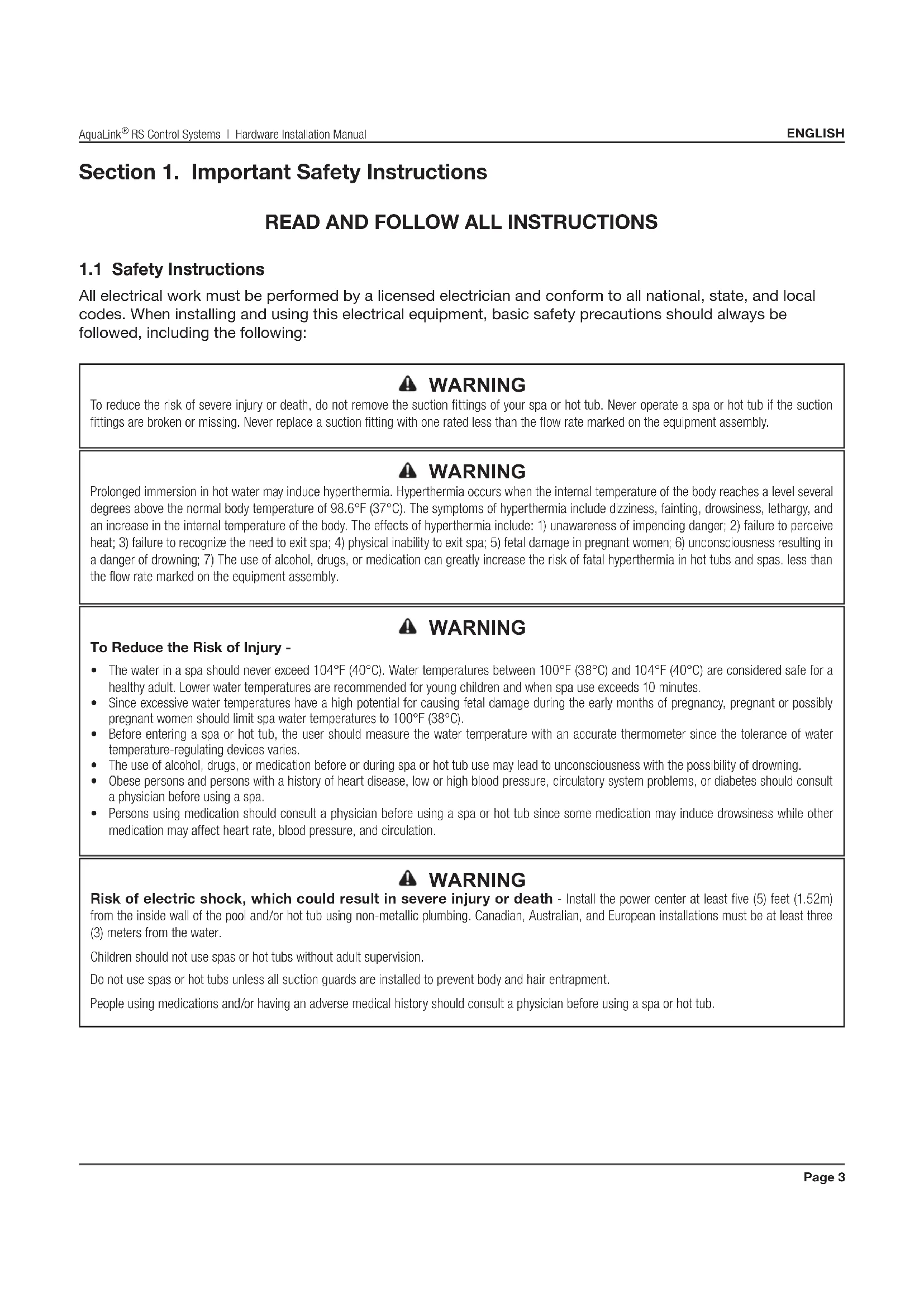
Dimensions

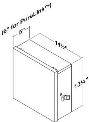
Standard Power Center
natural_image
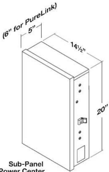
Technical line drawing of a mechanical device with a lever and coiled components (no text or symbols)iAquaLink Web-Connected Device
Suitable Listed Breakers (Available Locally)
| Manufacturer | CIRCUIT BREAKER | Filler Plate | ||||
| Single | Double | Twin | Quad | GFCB | ||
| Cutler-Hammer ^®1 Murray ^®2 Siemens ^®3 Square D ^®4 Thomas & Betts ^®5 | BRMP-TQPHOMTB | BRMP-TQPHOMTB | BRMH-TQTHOMT TBBD | BQCMH-TQTHOMTTBBQ | GFCBMP-GTQPFHOMGFB | BRFPLX100FPQF3HOMFP FP-1C-TB |
1 Cutler-Hammer is a registered trademark of Cutler-Hammer, Inc.
2 Murray is a registered trademark of Briggs & Statton Corp.
^3 Siemens is a registered trademark of Siemens Energy and Automation, Inc.
^4 Square D is a registered trademark of Square D Company.
^5 Thomas & Betts is a registered trademark of Thomas & Betts Corp.
2.2 Basic Plumbing
2.2.1 Plumbing for Pool and Spa Combination
The intake and return JVA's turn si mul ta neous ly so when the spa button is pressed on the AquaLink RS control panel, water circulation switches between pool and spa (consult the Jandy Valve Actuator Installation and Operation Manual to ensure that the JVA's are synchronized and rotate properly). Please consult the Jandy Valve® Plumb ing Manual for further examples of pool/spa plumbing.
For pool only/spa only or dual equipment plumbing, please refer to the Jandy Valve Plumbing Manual for further examples.
NOTE When the filter system is shared (a pool/spa combo), the spa water must be able to overflow back to the pool.
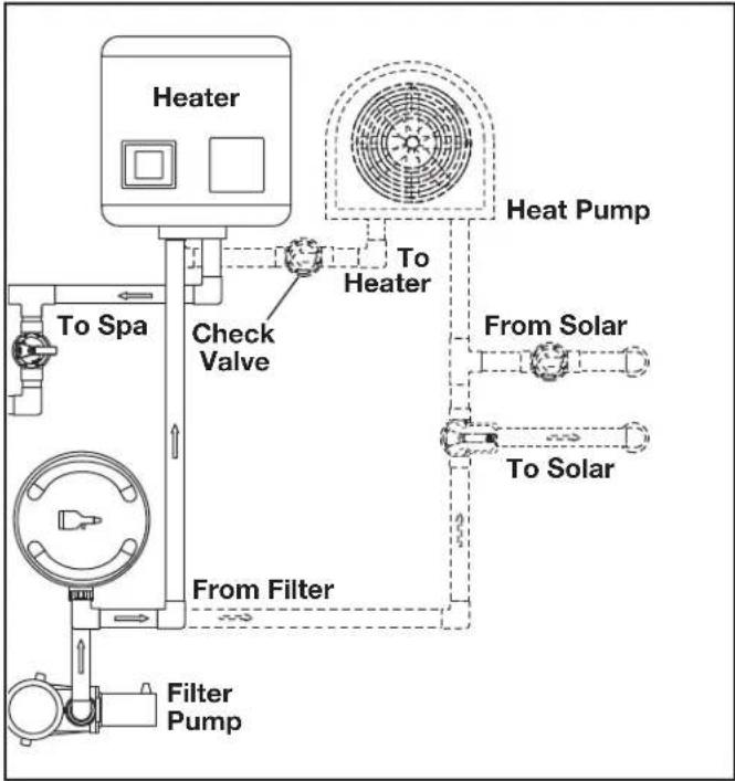
flowchart
graph TD
    A["Heater"] --> B["To Spa"]
    B --> C["Check Valve"]
    C --> D["From Filter"]
    D --> E["Filter Pump"]
    F["Heat Pump"] --> G["To Heater"]
    G --> H["From Solar"]
    H --> I["To Solar"]
Figure 1. Heat Pump Plumbing
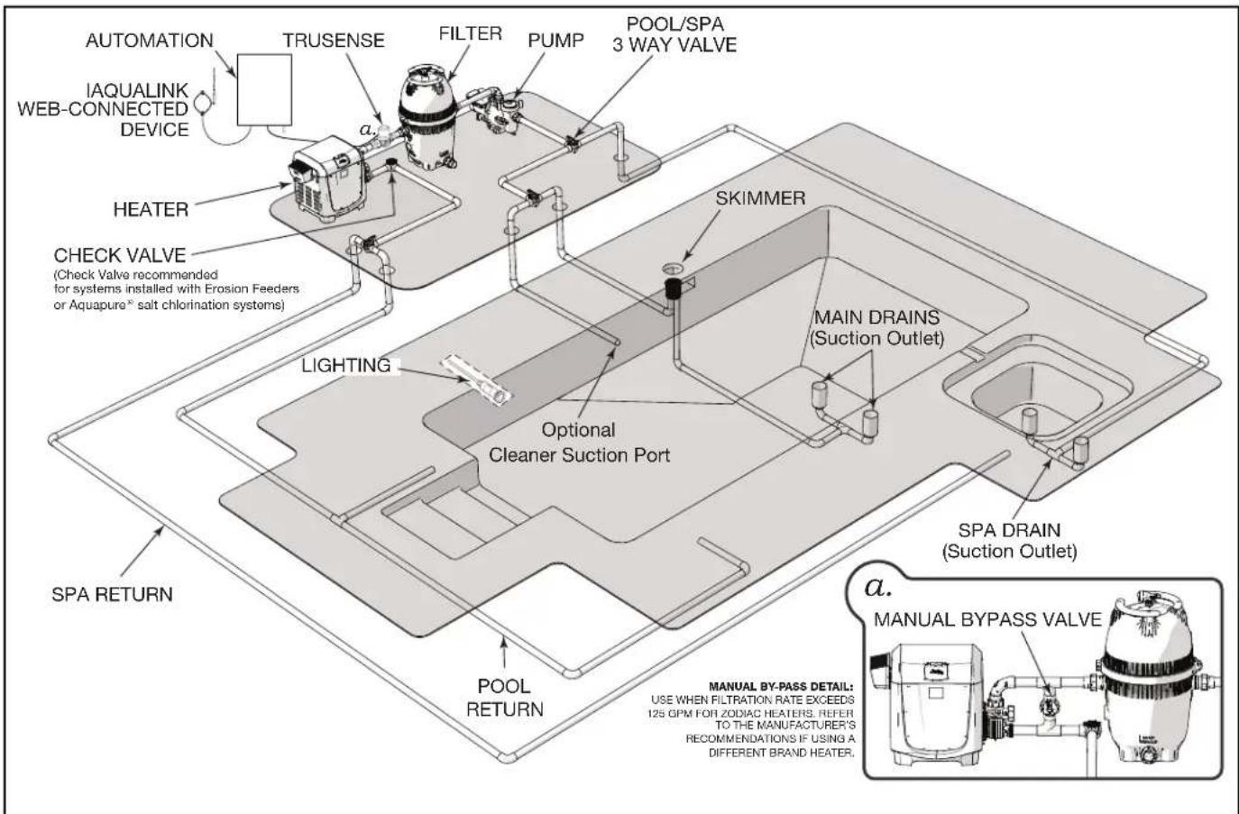
flowchart
graph TD
    A["AUTOMATION"] --> B["TRUSENSE"]
    C["IAQUALINK WEB-CONNECTED DEVICE"] --> B
    B --> D["FILTER"]
    D --> E["PUMP"]
    E --> F["POOL/SPA 3 WAY VALVE"]
    G["HEATER"] --> H["CHECK VALVE (Check Valve recommended for systems installed with Erosion Feeders or Aquapure® salt chlorination systems)"]
    H --> I["LIGHTING"]
    I --> J["Optional Cleaner Suction Port"]
    K["SPA RETURN"] --> L["POOL RETURN"]
    M["MAIN DRAINS (Suction Outlet)"] --> N["SKIMMER"]
    O["SPA DRAIN (Suction Outlet)"] --> P["MANUAL BY-PASS VALVE"]
    Q["a. MANUAL BY-PASS DETAIL: USE WHEN FILTRATION RATE EXCEEDS 12S QPM FOR ZODIAC HEATERS. REFER TO THE MANUFACTURER'S RECOMMENDATIONS IF USING A DIFFERENT BRAND HEATER."]
Figure 2. Typical Water Piping Confi guration
2.2.2 Booster Pump Pool Cleaner Plumbing
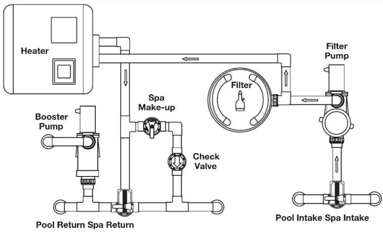
flowchart
graph TD
    A["Heater"] --> B["Booster Pump"]
    B --> C["Pool Return Spa Return"]
    C --> D["Check Valve"]
    D --> E["Spa Make-up"]
    E --> F["Filter"]
    F --> G["Filter Pump"]
    G --> H["Pool Intake Spa Intake"]
    style A fill:#f9f,stroke:#333
    style H fill:#bbf,stroke:#333
2.2.3 Non-Booster Pump Pool Cleaner Plumbing
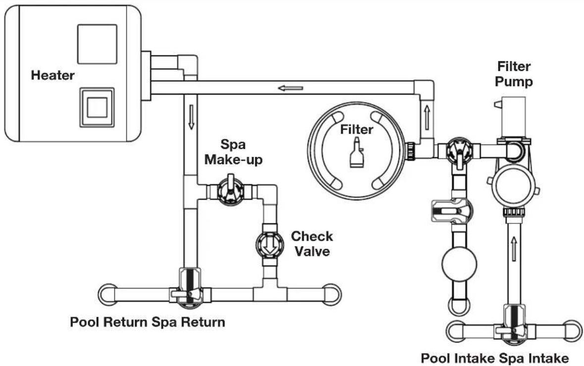
flowchart
graph TD
    A["Heater"] --> B["Spa Make-up"]
    B --> C["Check Valve"]
    C --> D["Pool Return Spa Return"]
    D --> E["Pool Intake Spa Intake"]
    F["Filter"] --> G["Filter Pump"]
    G --> H["Water Inlet"]
    style A fill:#f9f,stroke:#333
    style B fill:#ccf,stroke:#333
    style C fill:#cfc,stroke:#333
    style D fill:#fcc,stroke:#333
    style E fill:#cff,stroke:#333
    style F fill:#ffc,stroke:#333
    style G fill:#fcc,stroke:#333
    style H fill:#ffc,stroke:#333
Section 3. Installation
3.1 Power Center Mounting
- The power center should be located at or near the equipment pad. Locate the power center at least five (5) feet or more away from pool/spa and five (5) feet off the ground. All national, state, and local codes are applicable.
NOTE For Canadian installations, the power center must be at least three (3) meters (9.8 feet) away from the pool/spa and 1.5 meters (5 feet) above the ground.
-
Use the mounting brackets and instructions provided with the standard power center and/or sub-panel power center.
-
Sub-panel power centers have special code requirements. Be sure to follow all applicable local and state codes to insure safe installation.
NOTE The power center is not to be considered as suitable for use as service equipment. Therefore, it is required to have the appropriate means of disconnection, circuit isolation, and/or branch circuit protection installed upstream of the power center.
3.2 High Voltage Wiring
3.2.1 System Power
WARNING
Potentially high voltages in the AquaLink Power Center can create dangerous electrical hazards, possibly causing death, serious injury or property damage. Turn off power at the main circuit of the AquaLink Power Center to disconnect the Power Center from the system. To properly and safely wire the system, be sure to carefully follow the applicable requirements of the National Electrical Code ^® (NEC ^® ), NFPA 70 or the Canadian Electrical Code (CEC ^® ), CSA C22.1. All applicable local installation codes must also be adhered to.
Depending on the amount of equipment being controlled, run 12 " or 34 " conduit from the power supply panel to the bottom of the power center. If you are using the sub-panel power center, wire power to the appropriate breakers. Pull in appropriate wire for equipment. Each piece of equipment requires its own high voltage relay. Connect 120 volts for US/CAN to the power center terminals. Connect equipment ground(s). See Figures 3 and 4.
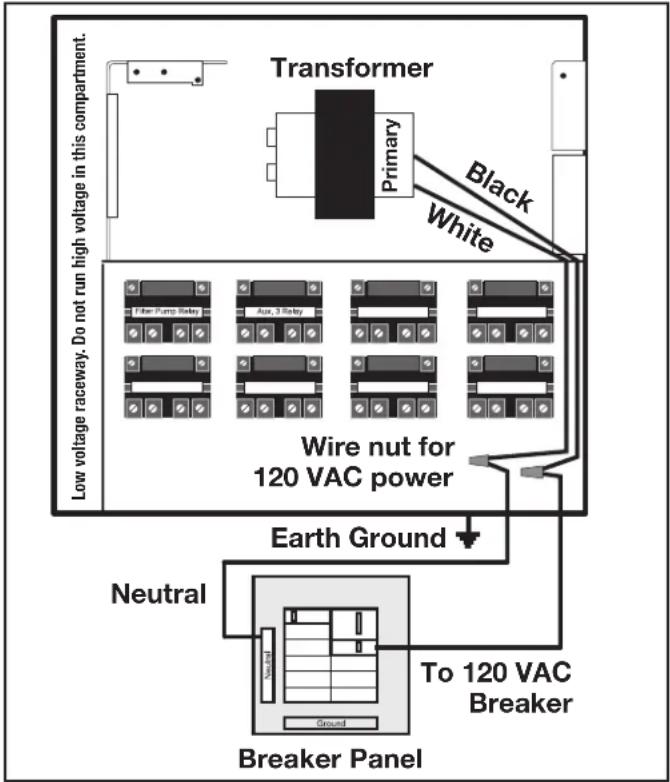
Figure 3. Standard Power Center
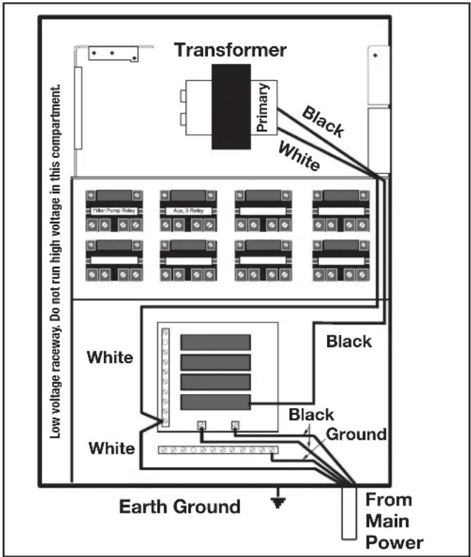
Figure 4. Sub-Panel Power Center
3.2.2 3HP (Standard) Relays
For each piece of 240 volt equipment to be controlled, connect line power to the two (2) line terminals and connect equipment power to the two (2) load terminals on the same relay.
For each piece of 120 volt equipment, connect power to a line terminal and connect equipment to a load terminal on the same relay.
NOTE The following are the contact ratings for 3HP (Standard) Relay. DO NOT exceed any ratings. 3 HP @ 240 VAC; 1½ HP @ 120 VAC; 25 Amps; 1500 Watts.
3.2.3 Bonding the Power Center
Install a bonding lug to the power center enclosure. Connect the bond lug, using a #8 solid copper core wire, to an approved earth ground (an approved ground stake, grid, or conducting metal water pipe buried to a sufficient depth). See Figure 5.
The National Electrical Code ^® (NEC ^® in the United States) or the Canadian Electrical Code (CEC in Canada) requires pool equipment to be bonded to each other. Check your local codes to determine if the NEC or CEC and/or other local installation codes are enforced by the Authority Having Jurisdiction
(AHJ in the United States) or the local competent authorities in Canada. A solid, copper 8.37 mm2 (8 AWG) wire is required per the NEC, and 13.3 mm ^2 (6AWG) per the CEC, for bonding the equipment to a permanent bonding connection that is acceptable to the local AHJ or the local competent authorities in Canada.
Refer to your locally enforced codes for the acceptable bonding wire gauge. Do not use the power center as the common bonding point. Each piece of non-related pool equipment requiring a ground should also be bonded to the common approved bonding point.
National Electrical Code ^® (NEC ^® ) requires bonding of the Pool Water. Where none of the bonded pool equipment, structures, or parts are in direct connection with the pool water; the pool water shall be in direct contact with an approved corrosion-resistant conductive surface that exposes not less than 5800 mm ^2 (9 in ^2 ) of the surface area to the pool water at all times. The conductive surface shall be located where it is not exposed to physical damage or dislodgement during usual pool activities, and it shall be bonded in accordance with the bonding requirements of NEC Article 680. Refer to locally enforced codes for any additional pool and spa bonding requirements
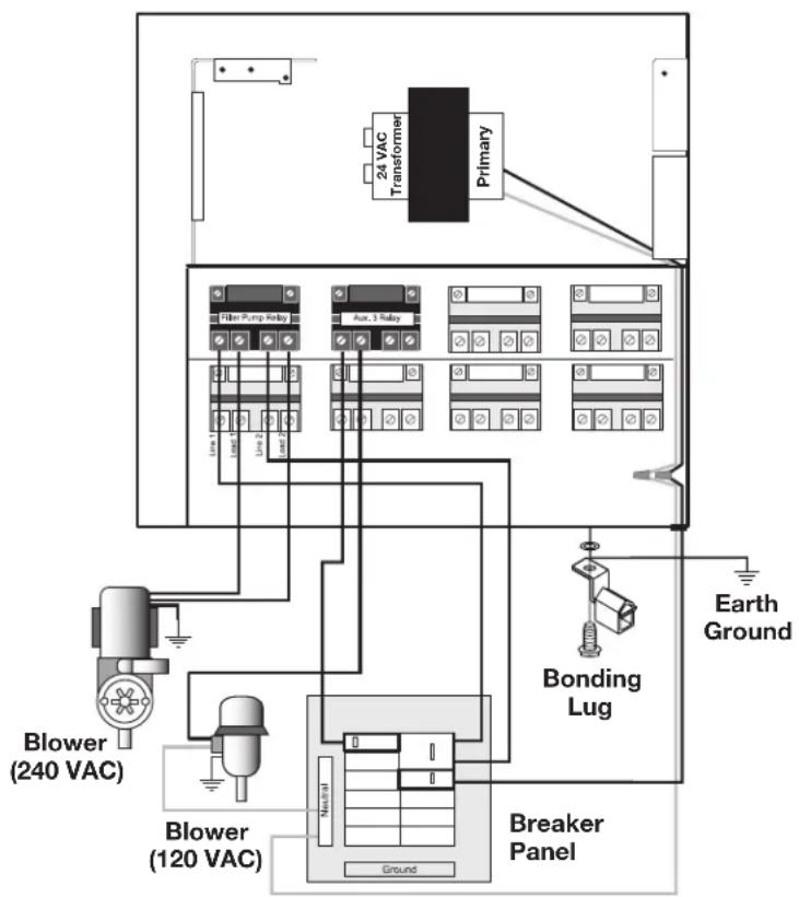
Figure 5. Standard Power Center - Bonding
3.2.4 High Voltage Underwater Lighting GFCI Wiring
CAUTION
A Ground Fault Circuit Interrupter (GFCI) must be provided in high voltage pool/spa lights. The conductors on the load side of the GFCI device shall not occupy conduit, boxes, or enclosures containing other conductors unless the other conductors are also on the load side of a GFCI, or unless the other conductors are segregated, separated by barrier(s) or routed and secured to provide permanent spacing from the conductors on the load side of the GFCI. Refer to local codes for complete details.
CAUTION
The AquaLink RS system is for fixed installations only and to be used in conjunction with swimming pool equipment. Also refer to the installation instructions relating to the swimming pool equipment for which the system will be an integral part. The system is to be supplied through a residual current device (RCD) with a rated residual operating current of 30mA. If the supply cord is damaged it must be replaced by the manufacturer or its service agent or similarly qualified person in order to avoid hazard.
- For a standard power center, install a GFCI receptacle or RCD next to the breaker panel. For a sub-panel power center install a GFCI receptacle in the power center (use the knockout provided on the right side of the sub-panel power center). See Figure 6.
- Connect neutral and hot wire (from circuit breaker) to the LINE side of the GFCI.
- Connect neutral (white wire) and the hot (black wire) from the light to the LOAD side of the GFCI.
- Connect ground from the light to the grounding bar inside the power center.
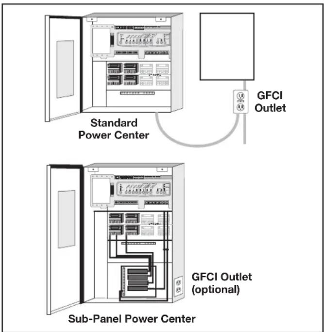
Figure 6. GFCI Installation for High Voltage Underwater Lighting
3.2.5 Jandy Pool and Spa Lights Wiring
The Jandy Pool and Spa Lights can be wired into the Jandy AquaLink RS control system to ensure simplified operation of the lights, as well as a means to synchronize the color change function. Connect the lights to one of the auxiliary relays in the power center.
NOTE It is recommended to connect one (1) light per relay so each light can be controlled separately. However, up to four lights can be connected on a single relay. If there are more than four (4) lights installed on one AquaLink RS system, ensure there is more than one (1) auxiliary relay available in the Power Center.
Refer to Figures 7 and 8 to connect the Jandy pool and spa lights to the power center.
NOTE The Jandy pool and spa lights are available in 120-volt and 12-volt versions. If installing a 12-volt light, a 120-volt/12-volt step-down (AC) transformer must be used. For more information about 12-volt installations, refer to the Jandy Digital, Color Changing, Underwater Pool and Spa Lights Installation and Operation Manual.
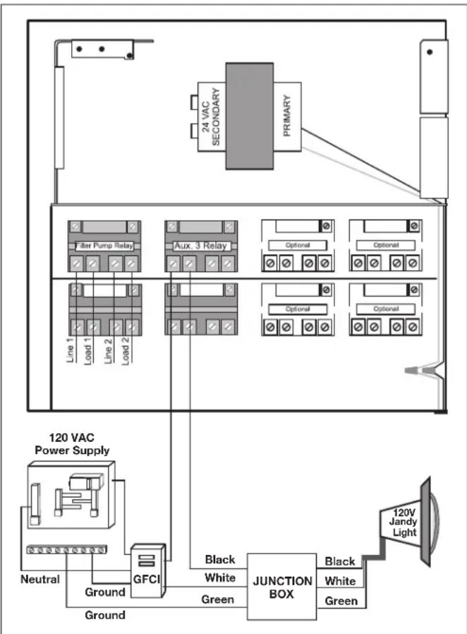
flowchart
graph TD
    A["120 VAC Power Supply"] --> B["Ground"]
    B --> C["GFCI"]
    C --> D["Black White Green Junction BOX"]
    D --> E["120V Jandy Light"]
    F["24 VAC SECONDARY PRIMARY"] --> G["Line 1 Load 1 Line 2 Load 2"]
    H["Filter Pump Relay"] --> I["Aux. 3 Relay"]
    J["Optional"] --> K["Optional"]
    L["Ground"] --> M["Ground"]
    N["Neutral"] --> C
    O["Alternative"] --> P["Alternative"]
    Q["Alternative"] --> R["Alternative"]
Figure 7. 120-Volt Jandy Pool and Spa Light Wiring Diagram
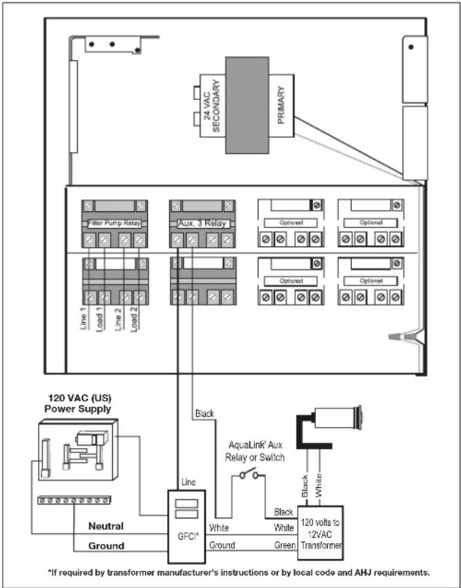
3.2.6 Infinite Watercolors Nicheless LED Light

WARNING
RISK OF ELECTRICAL SHOCK OR ELECTROCUTION,
which could result in serious injury or death. A Ground Fault Circuit Interrupter (GFCI) for 120 Volt transformers should be used if required by the transformer manufacturer or if required by the local applicable code and/or Authority Having Jurisdiction (AHJ). When a GFCI is used, the conductors on the load side of the GFCI circuit shall not occupy conduit, boxes, or enclosures containing other conductors unless the additional conductors are also protected by a GFCI. Refer to local codes for complete details.

WARNING
RISK OF ELECTRICAL SHOCK OR ELECTROCUTION,
which could result in serious injury or death. The Jandy Infinite WaterColors Nicheless LED Lights are only available for 14 Volt AC power. For supply connection, use only an isolating low voltage power supply with ungrounded output, evaluated and listed by a NRTL for swimming pool use.
flowchart
graph TD
    A["120 VAC (US) Power Supply"] --> B["Line 1"]
    A --> C["Line 2"]
    A --> D["Line 3"]
    A --> E["Line 4"]
    A --> F["Line 5"]
    A --> G["Line 6"]
    A --> H["Line 7"]
    A --> I["Line 8"]
    A --> J["Line 9"]
    A --> K["Line 10"]
    A --> L["Line 11"]
    A --> M["Line 12"]
    A --> N["Line 13"]
    A --> O["Line 14"]
    A --> P["Line 15"]
    A --> Q["Line 16"]
    A --> R["Line 17"]
    A --> S["Line 18"]
    A --> T["Line 19"]
    A --> U["Line 20"]
    A --> V["Line 21"]
    A --> W["Line 22"]
    A --> X["Line 23"]
    A --> Y["Line 24"]
    A --> Z["Line 25"]
    A --> AA["Line 26"]
    A --> AB["Line 27"]
    A --> AC["Line 28"]
    A --> AD["Line 29"]
    A --> AE["Line 30"]
    A --> AF["Line 31"]
    A --> AG["Line 32"]
    A --> AH["Line 33"]
    A --> AI["Line 34"]
    A --> AJ["Line 35"]
    A --> AK["Line 36"]
    A --> AL["Line 37"]
    A --> AM["Line 38"]
    A --> AN["Line 39"]
    A --> AO["Line 40"]
    A --> AP["Line 41"]
    A --> AQ["Line 42"]
    A --> AR["Line 43"]
    A --> AS["Line 44"]
    A --> AT["Line 45"]
    A --> AU["Line 46"]
    A --> AV["Line 47"]
    A --> AW["Line 48"]
    A --> AX["Line 49"]
    A --> AY["Line 50"]
    A --> AZ["Line 51"]
    A --> BA["Line 52"]
    A --> BB["Line 53"]
    A --> BC["Line 54"]
    A --> BD["Line 55"]
    A --> BE["Line 56"]
    A --> BF["Line 57"]
    A --> BG["Line 58"]
    A --> BH["Line 59"]
    A --> BI["Line 60"]
    A --> BJ["Line 61"]
    A --> BK["Line 62"]
    A --> BL["Line 63"]
    A --> BM["Line 64"]
    A --> BN["Line 65"]
    A --> BO["Line 66"]
    A --> BP["Line 67"]
    A --> BQ["Line 68"]
    A --> BR["Line 69"]
    A --> BS["Line 70"]
    A --> BT["Line 71"]
    A --> BU["Line 72"]
    A --> BV["Line 73"]
    A --> BW["Line 74"]
    A --> BX["Line 75"]
    A --> BY["Line 76"]
    A --> BZ["Line 77"]
    A --> CA["Line 78"]
    A --> CB["Line 79"]
    A --> CC["Line 80"]
    A --> CD["Line 81"]
    A --> CE["Line 82"]
    A --> CF["Line 83"]
    A --> CG["Line 84"]
    A --> CH["Line 85"]
    A --> CI["Line 86"]
    A --> CJ["Line 87"]
    A --> CK["Line 88"]
    A --> CL["Line 89"]
    A --> CM["Line 90"]
    A --> CN["Line 91"]
    A --> CO["Line 92"]
    A --> CP["Line 93"]
    A --> CQ["Line 94"]
    A --> CR["Line 95"]
    A --> CS["Line 96"]
    A --> CT["Line 97"]
    A --> CU["Line 98"]
    A --> CV["Line 99"]
    A --> CW["Line 100"]

    subgraph Power Supply
        direction TB
        direction LR
        Black
        White
        Green
        Black
        White
        Black
        White
        Green
        Black
        White
        Black
        White
        Black
        White
        Black
        White
        Black
        White
        Black
        White
        Black
        White
        Black
        White
        Black
        White
        Black
        White
        Black
        White
        Black
        White
        Black
        White
        Black
        White
        Black
        White
        Black
        White
        Black
        White
        Black

    Note: The diagram shows a schematic of a transformer with labels for each component and connection points. The legend is embedded in the diagram as it is not explicitly labeled in the code.
Figure 8. 12-Volt Jandy Pool and Spa Light Wiring Diagram
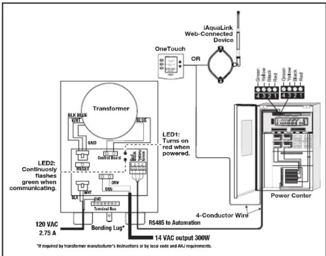
The Jandy Infinite WaterColors Nicheless LED Lights must be controlled by the Infinite WaterColors LED Light Controller and AquaLink automation system.
Refer to Figure 9 to connect the Jandy Infinite WaterColors Nicheless LED Lights and to the Infinite WaterColors LED Light Controller manual for connecting the Infinite WaterColors LED Light Controller to the AquaLink automation system.
- Knock out an opening in the right compartment.
- Run low voltage light through a cord grip and secure to the enclosure
- Connect the low voltage wires black to orange and white to orange. See Figure 9.
3.2.7 Wire Gauge and Length
CAUTION
Jandy ^® Nicheless Underwater LED Lights are low voltage fixtures. Improper wire gauge and wire length can effect the performance of these products. Follow the guidelines below to determine the proper operation and optimum performance of the lights.
The output voltage of the Infinite WaterColors LED Light Controller is 14 VAC to accommodate the voltage drop across cords up to 200 ft. Installations should not exceed 200 ft.
NOTE Each color mode has a slightly different power draw
3.2.8 Fourteen (14) Volt Installation
The Infinite WaterColors LED Light Controller IS required to power Infinite WaterColors Lights.
NOTE For optimum performance do not exceed the load factor specified by the instructions included with the transformer.
3.2.9 RS-485 Connection
See low voltage wiring, Section 3.3.
To ensure maximum safety, use only the Jandy Infinite WaterColors LED Light Controller listed for swimming pool and spa use.
CAUTION
To prevent risk of fire which could result in property damage, and to ensure optimum performance, do not exceed the load factor specified in the instructions provided by the transformer manufacturer.
flowchart
graph TD
    A["Transformer"] -->|BLK BLUE VIRT| B["LED2: Continuously flashes green when communicating."]
    A -->|GREEN GND| C["Control Board"]
    A -->|RESET| D["Terminal Bus"]
    A -->|ONIN| E["RS485 to Automation"]
    A -->|ONIN| F["120 VAC 2.75 A"]
    A -->|ONIN| G["Bonding Lug*"]
    A -->|ONIN| H["14 VAC output 300W"]
    A -->|ONIN| I["RS485 to Automation"]
    A --> J["OneTouch"]
    J --> K["OR"]
    K --> L["iAquaLink Web-Connected Device"]
    L --> M["Green Yellow Black Red Green Yellow Black Red"]
    L --> N["Power Center"]
    N --> O["4-Conductor Wire"]
    O --> P["Red"]
    O --> Q["Red"]
    O --> R["Red"]
Figure 9. Wiring LED Lights to the Infinite WaterColors LED Light Controller
3.2.10 Variable Speed Pump Wiring (High Voltage)
With the AquaLink it is possible to control up to sixteen (16) variable speed pumps. This section describes how to supply AC power to the pumps. For instructions on how to connect the low voltage communications wiring (RS485) see Section 3.3.3.
3.2.11 Jandy Variable Speed Pump
For pump high voltage wiring specifications and instructions, please refer to the installation/operation manual of the corresponding pump.
WARNING
Potentially high voltages in the AquaLink Power Center can create dangerous electrical hazards, possibly causing death, serious injury or property damage. Turn off power at the main circuit of the AquaLink Power Center to disconnect the Power Center from the system. To properly and safely wire the system, be sure to carefully follow the applicable requirements of the National Electrical Code ^® (NEC ^® ), NFPA 70 or the Canadian Electrical Code (CEC ^® ), CSA C22.1. All applicable local installation codes must also be adhered to.
To connect a Jandy variable speed pump to a dedicated circuit breaker.
- Make sure all electrical breakers and switches are turned off before wiring the motor.
- Make sure the wiring voltage is appropriate for the pump model being used. Refer to the pump installation manual for specifications.
- Use #12 AWG for wire runs up to 100 feet and #10 AWG for lengths longer than 100 feet. When in doubt use a heavier gauge (larger diameter) wire. Heavier gauge will allow the motor to run cooler and more efficient.
- Make sure all electrical connections are clean and tight.
- Strip the wires to the appropriate length so they do not overlap or touch when connected.
- Permanently ground the motor using the green ground wire, as shown in Figure 10. Use the correct wire size and type specified by National Electrical Code (NEC) and the Canadian Electrical Code (CEC). Make sure the ground wire is connected to an electrical service ground.
- Bond the motor to the pool structure in accordance with the National Electrical Code (NEC) and the Canadian Electrical Code (CEC). Use a solid No. 8 AWG or larger copper conductor (US). Run a wire from the external
bonding lug to the pool bonding structure, as shown in Figure 10.
- Connect the red and black wires of the pump to the two line side connections on the filter pump relay as shown in Figure 10.
- Refer to low voltage Section 3.3.4 to connect the RS-485 communication wiring.
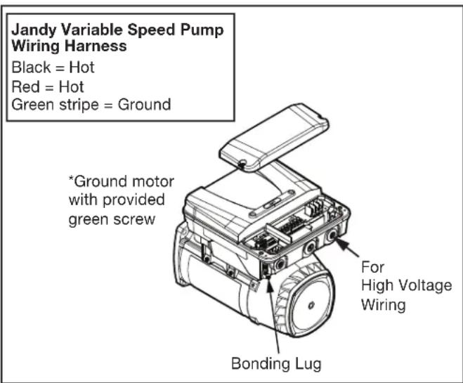
Figure 10. Jandy External Bonding
3.2.12 Pentair® Variable Speed/Flow Pumps
WARNING
Potentially high voltages in the AquaLink Power Center can create dangerous electrical hazards, possibly causing death, serious injury or property damage. Turn off power at the main circuit of the AquaLink Power Center to disconnect the Power Center from the system. To properly and safely wire the system, be sure to carefully follow the applicable requirements of the National Electrical Code ^® (NEC ^® ), NFPA 70 or the Canadian Electrical Code (CEC ^® ), CSA C22.1. All applicable local installation codes must also be adhered to.
To connect a Pentair variable speed/flow pump to the AC power.
- Make sure all electrical breakers and switches are turned off before wiring the motor.
- Make sure that the wiring voltage is 230 VAC.
- Use #12 AWG for wire runs up to 100 feet and #10 AWG for lengths longer than 100 feet. When in doubt use a heavier gauge (larger diameter) wire. Heavier gauge will allow the motor to run cooler and more efficient.
-
Make sure all electrical connections are clean and tight.
-
Cut the wires to the appropriate length so they do not overlap or touch when connected.
- Permanently ground the motor using the green ground wire, as shown in Figure 11. Use the correct wire size and type specified by National Electrical Code® (NEC®) and the Canadian Electrical Code (CEC®). Make sure the ground wire is connected to an electrical service ground.
- Bond the motor to the pool structure in accordance with the National Electrical Code (NEC) and the Canadian Electrical Code (CEC). Use a solid No. 8 AWG or larger copper conductor (US). Run a wire from the external bonding lug to the pool bonding structure, as shown in Figure 11.
- Connect the two red hot wires of the pump to the two line side connections on the filter pump relay as shown in Figure 11.
- Refer to low voltage Section 3.3.4 to connect the RS-485 communication wiring.

Figure 11. Pentair External Bonding
3.3 Low Voltage Wiring
Minimum wire size should be 22 AWG. If wire run is more than 300 feet, larger wire should be used. Two (2) RS485 4 pin red terminals are provided on the RS power center board. For additional connections utilize a multiplex PCB, part #6584.
3.3.1 Bezel Connection
Plug the 24 VAC power plug from the transformer into its 3-pin terminal on the back of the power center PCB as shown in Figure 12. Mount the bezel to the power center using the screws provided.
24 VAC Power Plug Connection
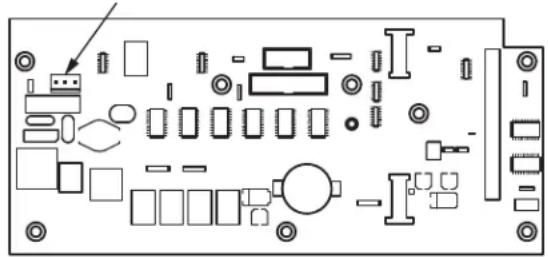
natural_image
Pure electrical circuit lines without any symbolsFigure 12. Power Center PCB (back view)
3.3.2 Control Panel Cable to Power Center PCB
Make provision for the four conductor, 22 AWG or larger cable to be run between the indoor control panel and the power center. Never run high voltage and low voltage in the same conduit. Pull cable through the knockout with the Heyco ^®1 fitting and into the low voltage compartment. Strip back jacket 6". Strip each wire a 1/4" and connect to the red, 4-pin connector on the power center PCB. A multiplex kit may be required if there are more than two cables running to a red, 4-pin connector. See Figure 13.
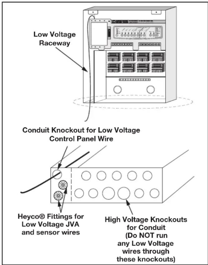
Figure 13. Control panel Cable to Power Center PCB
3.3.3 Variable Speed Pump to Power Center PCB Cable
The low voltage wiring for the variable speed pumps consists of the RS485 communications four conductor, 22 AWG or larger cable. Make provision for the cable to be run between the pump and the power center. Never run high voltage and low voltage in the same conduit. Pull cable through the knockout with the Heyco fitting and into the low voltage compartment. Strip back jacket 6". Strip each wire a 1/4" and connect to the red, 4-pin connector on the power center PCB. A multiplex kit may be required if there are more than two cables running to each of the red, 4-pin connectors on the power center PCB. See Figure 14.
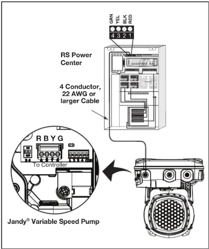
Figure 14. Low Voltage Wiring for Jandy Variable Speed Pump
3.3.4 Wiring the Jandy Variable Speed Pump
Connection from the AquaLink power center PCB to the Jandy ePump is via an RS485 cable. The cable pin out is shown below.
| RS485 Wire Connections for Jandy ePump | |
| This side connects to J1 or J4 of power center PCB or to the multiplexer PCB. | This side of the cable connects to the Jandy ePump. |
| Pin 1(no connection, not used) | Pin 1(no connection, not used) |
| Pin 2 (SD+) Pin 2 (SD+) | |
| Pin 3 (SD-) Pin 3 (SD-) | |
| Pin 4(no connection, not used) | Pin 4(no connection, not used) |
3.3.5 Jandy Variable Speed Pump DIP switch settings
Dipswitch Settings with Local Controller
Please refer to the following table for required settings for Dip switches 3-4 when the pump is connected to a local controller.
| Local Controller DIP Switch Settings | ||
| Controller | Switch 3 Switch | 4 |
| JEP-R OFF | OFF | |
| iQPUMP01 | OFF OFF | |
| SpeedSet | Dip Switch 3-4 settings are only important when connected to a Jandy automation system using SpeedSet automation pass-through wiring connection on the bottom of the controller.If applicable, please see following sections. | |
Dip Switch Settings with Automation
Dip Switch 3-4 setting rules are not common across all Jandy automation systems. Please reference the following sections to understand the required settings.
For Jandy Aqualink RS Automation System users, a 2022 mid-year update changes the method in which pumps in this manual interact with Jandy Aqualink RS systems. Refer to the RS manual for more information.
Pre-2022 Aqualink RS Firmware Rev\_V and Earlier
Aqualink RS systems using firmware Rev V and earlier, manufactured prior to mid-year 2022, support up to 4 variable-speed pumps. Each pump is assigned an address of 1 through 4 using Dip Switches 3-4 on the pump. Use the table below for pump address assignment settings.
These settings are used when connected to the RS485 connection on the pump or when connected to the pump using a SpeedSet controller's automation pass-through wiring connection on the bottom of the controller.
| Local Controller DIP Switch Settings | ||
| Address | Switch 3 Switch | 4 |
| Pump 1 OFF | OFF | |
| Pump 2 ON | OFF | |
| Pump 3 | OFF ON | |
| Pump 4 ON | ON | |
2022 Aqualink RS Firmware Rev W and Later
Aqualink RS systems using Rev W and later, manufactured after mid-year 2022, support up to 16 variable-speed pumps that utilize a pre-assigned PUMP ADDRESS. Dip Switches 3-4 are not utilized. Pumps in this manual are all assigned a unique PUMP ADDRESS at the factory. The PUMP ADDRESS label can be found on the pump motor in the location shown below.
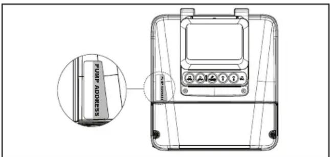
Figure 15. Pump Address Label Location
When setting up pumps using this method, the pump address of each pump will initially appear in the unassigned pump address section of the iAqualink App or other automation setup device. Utilize the App or other device to complete pump setup.
3.3.6 Wiring the Pentair ^® Pump
The Pentair IntelliFlo® VF LCD control panel is disabled when communicating with the AquaLink system and “DISPLAY NOT ACTIVE” will be displayed. Note that AquaLink RS will not start communicating with the Pentair IntelliFlo VF until it has been configured accordingly. See the AquaLink Owner’s Manual (P/N 6593L) for more information.
Connection from the AquaLink power center PCB to the Pentair variable speed/flow pumps is via the two-wire cable (Pentair P/N 350122). The cable pin out is shown in Figure 16.
In order to operate up to four (4) Pentair variable speed pumps the motor must be addressed. Refer to the Pentair manual for instructions.
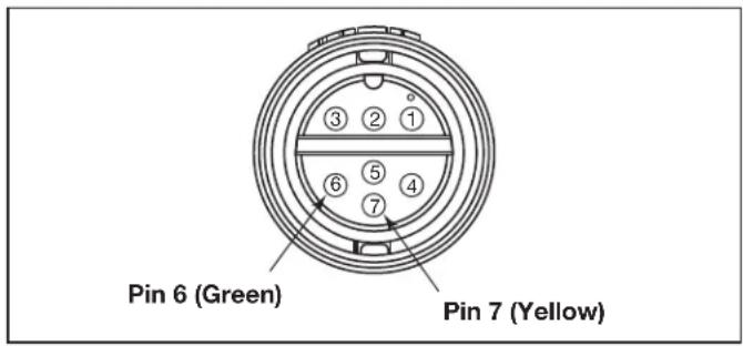
Figure 16. Cable Connector at the Pump Side
| Jandy RS485 (RED) Connector | Pentair RS485 Cable Assembly |
| Pin 1 (no connection) | |
| Pin 2 Yellow Wire | |
| Pin 3 Green Wire | |
| Pin 4 (no connection) |
3.4 Heater Connection
The heater connection section applies to all heaters or heat pumps with thermostatic circuitry of 24 VAC or less.
NOTE If you are connecting a heater with thermostatic circuitry of 120 VAC or greater, do not connect to the green, 10-pin terminal bar. Instead connect the heater to a high voltage relay in the power center and plug the spare relay into the electric heater relay socket on the power center PCB.
3.4.1 Jandy Heater Connections
-
Connect two #14 gauge wires, designed for use in hot environments, to the #1 and #2 terminals on the green, 10-pin terminal bar.
-
Connect the other ends of the #14 gauge wires from step 1 to the fireman's switch terminal bar in place of the factory installed wire loop.
- Do not disconnect high limit or pressure switches.
- Turn the heater thermostat(s) to maximum setting.
- Turn the heater switch to the ON position. For dual thermostat heaters turn switch to Spa position.
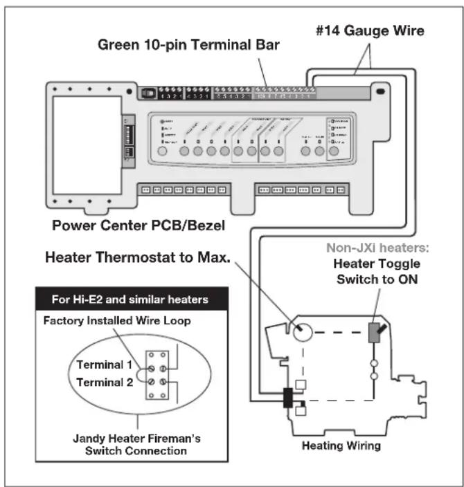
Figure 17. Jandy Heater Connection
3.4.2 Guidelines for Sophisticated Diagnostic Communication to Jandy JXi™ Heaters
- Confirm the JXi heater software and AquaLink RS software revisions are compatible (see tables below).
- Run a 4-conductor cable from the JXi heater or the Air Energy heat pump power interface red, 4-pin connector to the power center red, 4-pin connector (see Figure 18).
| JXi Power Interface Software Revision | AquaLink RS Software Revision |
| Any N or Later |
NOTE If connecting more than two (2) items to the power center red, 4-pin connector, a multiplex PCB (P/N 6584) is required.
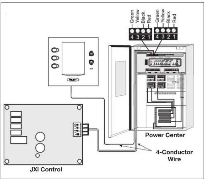
Figure 18. Jandy JXi Heater Connection to Power Center
3.4.3 Other Brands Heater and Pump Connections
To set up heater connections on heaters and heat pumps made by other manufactures, please refer to the Installation Manual provided with these heaters and heat pumps.
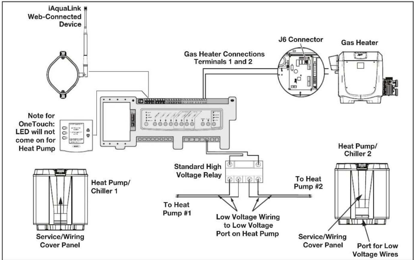
3.4.4 Guidelines for a Gas Heater and a Heat Pump/Chiller Installation
NOTE The following steps provide the procedure for installing a Jandy JRT Series Heat Pump and controlling it with the solar pump relay. If your Jandy JRT Series Heat Pump is equipped with an RS485 Interface then you do not need to use the solar pump relay to control it. You can control the heat pump via the RS485 interface of the AquaLink RS.
- Set DIP switch S2 bit 1 to the ON position. The AquaLink will auto-relabel solar as heat pump.
- To run the wires from the heat pump control panel, remove the five (5) screws that attach the service/wiring cover panel to the heat pump. See Figure 19.
flowchart
graph TD
    A["iAquaLink Web-Connected Device"] --> B["Note for OneTouch: LED will not come on for Heat Pump"]
    B --> C["Gas Heater Connections Terminals 1 and 2"]
    C --> D["J6 Connector"]
    D --> E["Gas Heater"]
    C --> F["Standard High Voltage Relay"]
    F --> G["To Heat Pump #1"]
    F --> H["Low Voltage Wiring to Low Voltage Port on Heat Pump"]
    H --> I["Service/Wiring Cover Panel"]
    F --> J["Heat Pump/Chiller 1"]
    F --> K["Heat Pump/Chiller 2"]
    style A fill:#f9f,stroke:#333
    style B fill:#ccf,stroke:#333
    style C fill:#cfc,stroke:#333
    style D fill:#fcc,stroke:#333
    style E fill:#cff,stroke:#333
    style F fill:#ffc,stroke:#333
    style G fill:#cfc,stroke:#333
    style H fill:#fcc,stroke:#333
    style I fill:#cfc,stroke:#333
    style J fill:#fcc,stroke:#333
    style K fill:#cfc,stroke:#333
Figure 19. Heater and Heat Pump/Chiller Wiring
- Run the wires from the heat pump control panel through the wiring conduit located on the outer right hand side of the heat pump.
- Connect the heat pump to a standard relay, then connect the relay to the solar pump output on the AquaLink PCB.
- The solar button will activate the heat pump/chiller and the pool and/or spa heater buttons will activate the gas heater. In this manner the pool or spa can be heated or chilled by the heat pump, the gas heater or both.
NOTE To program the heat pump control panel, refer to the Heat Pump Manual.
3.5 Temperature Sensors
- Drill 3/8" hole in pipe between filter pump and filter and install the water temperature sensor per instructions (make certain the o-ring is in place).
- Install air temperature sensor outside the power center can, not in direct sunlight and away from motors and other heat sources.
- Install solar temperature sensor (optional) adjacent to solar panels.
NOTE If a solar sensor is not installed, the solar button can be labeled and used as an extra auxiliary.
4. Run the wire to the power center, through the low voltage raceway. Cut off excess wire. Strip the wire jacket back 6", then strip each wire 14 ". Connect sensor wires to the green, 10-pin terminal bar (see Figure 20).
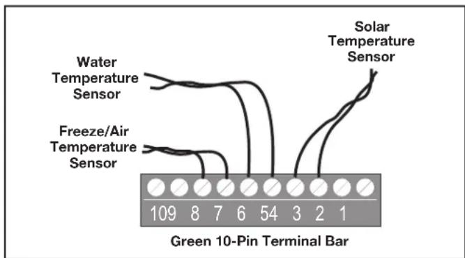
Figure 20. Temperature Sensor Wiring for a Pool/Spa Combination
3.6 Jandy Valve ^® Actuators
NOTE Mount the JVA's according to the Jandy Valve Actuator Installation and Operation Manual.
JVA cable is type SJW-A marked water resistant class 3 cable and does not require conduit. Knockouts and Heyco® fittings are provided in the low voltage raceway.
- Route the JVA wire to the power center.
- Run the wire through the low voltage raceway and plug the JVA connectors into their proper sockets (see Section 6. Power Center Wiring Diagram). Verify that the JVA on the suction plumbing is connected to the Intake JVA Socket, and the discharge plumbing is connected to the Return JVA Socket.
NOTE Do not coil the JVA wires inside power center. To shorten the wire, remove the JVA cover and disconnect the wire. Shorten, strip, and reconnect.
- For alternate plumbing configurations the JVA cam settings can be adjusted as needed. See the Jandy Valve Actuator Installation and Operation Manual, Cam Setting Chart for proper settings.
3.7 Jandy TruSense Water Chemistry Analyzer
NOTE: Always install TruSense after the filter and before the heating system and water care devices (saltwater chlorinator cell, chlorinator, acid injection...).
- Run the RS485 cable from the TruSense Water Chemistry analyzer to the AquaLink RS power center.
- Route the four conductor RS485 cable through the low voltage raceway and connect the red connector to the automation system. See Figure 21b.
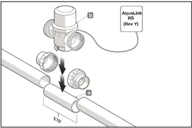
Figure 21. TruSense Calibration Application
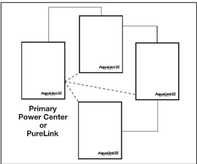
3.8 Auxiliary Power Centers
AquaLink RS All button models support one (1) auxiliary power center.
AquaLink RS models support a maximum of three (3) auxiliary power centers.
- The auxiliary power centers may be wired "in series", starting from the primary power center (solid line) or wired "in parallel" from the primary power center (dashed line). See Figure 22.
- Run four conductor, 22 AWG or larger cable between the red, 4-pin ter mi nal bars in each power center.
flowchart
graph TD
    A["Primary Power Center or PureLink"] --> B["AquaLink"]
    A --> C["AquaLink"]
    A --> D["AquaLink"]
    A --> E["AquaLink"]
    B -.-> C
    C -.-> D
    E -.-> D
Figure 22. Wiring Multiple Power Centers
NOTE
- All temperature sensors, heater connections and the main filter pump must be wired to the primary power center.
- Never put more than two (2) wires into each of the pins of the red, 4-pin terminal bar (use a Jandy® multiplex board).
- If more than one auxiliary power center is installed, set the jumpers as shown in Figure 23.
NOTE In the 2nd, 3rd, or 4th power centers, light dimming relay must be connected to auxiliary B5-B8, C5-C8, or D5-D8.
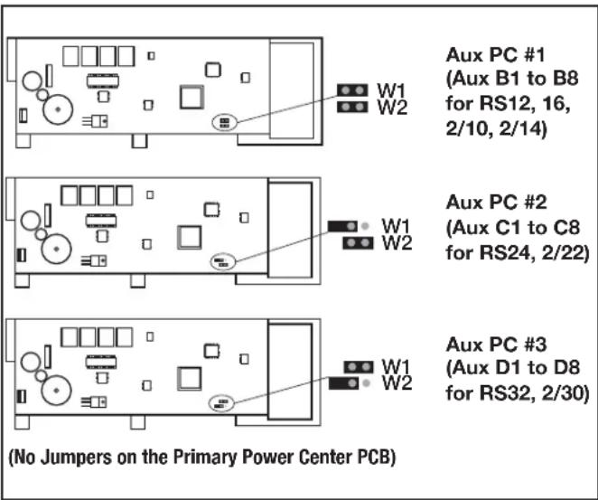
Figure 23. Setting Jumpers for Multiple Auxiliary Power Centers
3.9 OneTouch Control Panel Indoor Installation
3.9.1 Surface Mount OneTouch Indoor Installation
- With the aid of the homeowner, find the best location for the control panel.
- Place surface mount box in the location chosen for the control panel. Mark the holes for drilling. Drill 3/16" holes for the sheet rock anchors and a 1¼" hole for the 4-conductor cable.
- Run the 4-conductor cable from the power center to the location of the control panel (see Figure 24).
- Pull the 4-conductor cable through the hole in the wall and the hole in the surface mount box. Mount the box to the wall using the screws provided.
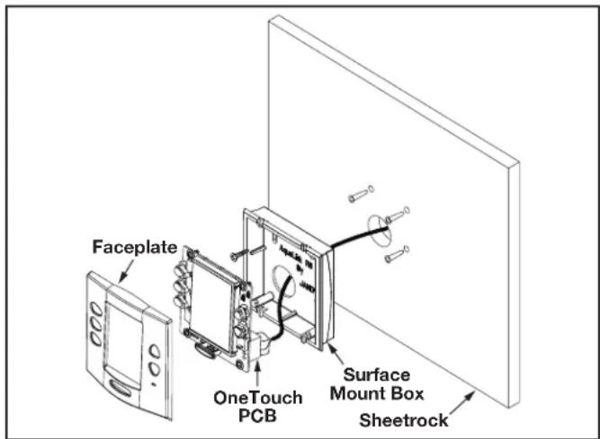
Figure 24. OneTouch™ Surface Mount Installation
- Wire the 4-conductor cable to the red, 4-pin terminal bar (see Figure 25). Push the 4-pin terminal bar onto the back of the OneTouch PCB. Place the PCB with LCD and buttons back into the box. Insert the screws and hand tighten. Do not overtighten. Snap the faceplate into place.
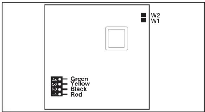
Figure 25. OneTouch PCB - Back View
3.9.2 Flush Mount OneTouch Indoor Installation
- With the aid of the homeowner, find the best location for the control panel.
- Place the flush mount box in the location chosen for the control panel. Level the box and trace around the outside of the box with a pencil. Cut the hole being careful not to oversize.
- Route the 4-conductor cable from the power center to the indoor control panel.
-
Pull the 4-conductor cable through the hole in the wall and the hole in the flush mount box. Push the flush mount box into the hole in the wall with the correct orientation (see Figure 26).
-
Depending on what size sheet rock (5/8" or 1/2"), determine which side of the cleat is to be facing you (see Figure 27).
- Insert a screw through the screw boss (see Figure 26). Put a cleat into the top "U" shaped hole. Hand tighten the screw and repeat the process for the bottom cleat.
- Wire the 4-conductor cable to the red, 4-pin terminal bar. Push the 4-pin terminal bar onto the back of the OneTouch PCB. Place the OneTouch PCB back into the Flush Mount Housing. Insert the screws with rubber washers and hand tighten. Do not overtighten. Snap the faceplate into place.
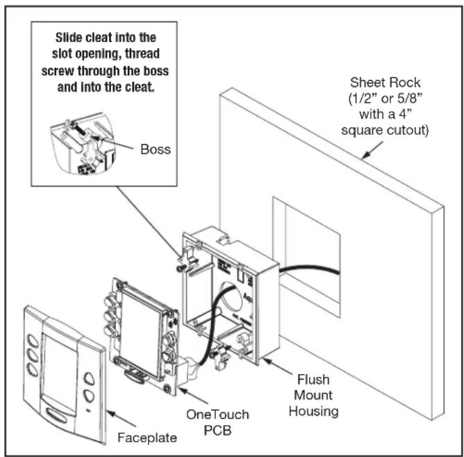
Figure 26. OneTouch Flush Mount Installation
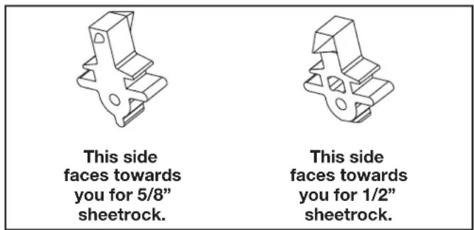
Figure 27. Cleat Orientation
3.9.3 Multiple AquaLink RS OneTouch Control Panel Indoor Installation
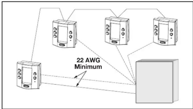
The AquaLink RS allows each system to support a maximum of 4 indoor control panels (see Figure 28). The control panels may be wired “in series” starting from the first control panel (solid lines), or wired “in parallel” from the AquaLink RS power center (dotted lines), or any combination of the two. In other words, any number of indoor control panels and/or power centers can be connected by means of the red, 4-pin terminal bar in any combination of “series” or “parallel” wiring.
NOTE Minimum wire size should be 22 AWG. If more than one control panel is installed, or the length of run is more than 300 feet, larger wire should be used.
flowchart
graph TD
    A["Device 1"] --> B["Device 2"]
    C["Device 3"] --> D["Device 4"]
    E["Device 5"] --> F["Device 6"]
    B --> G["Server"]
    D --> G
    F --> G
    style G fill:#cccccc,stroke:#333
Figure 28. Installing Multiple OneTouch Control Panels
3.9.4 AquaLink RS OneTouch Control Panel Jumper Settings
Move these jumpers only when installing more than one control panel on a system (see Figure29). The jumpers are used to give each control panel a unique system address. When replacing an existing control panel, change the jumper settings to match those on the one being replaced.
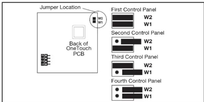
Figure 29. Jumper Settings for Multiple OneTouch™ Control Panels
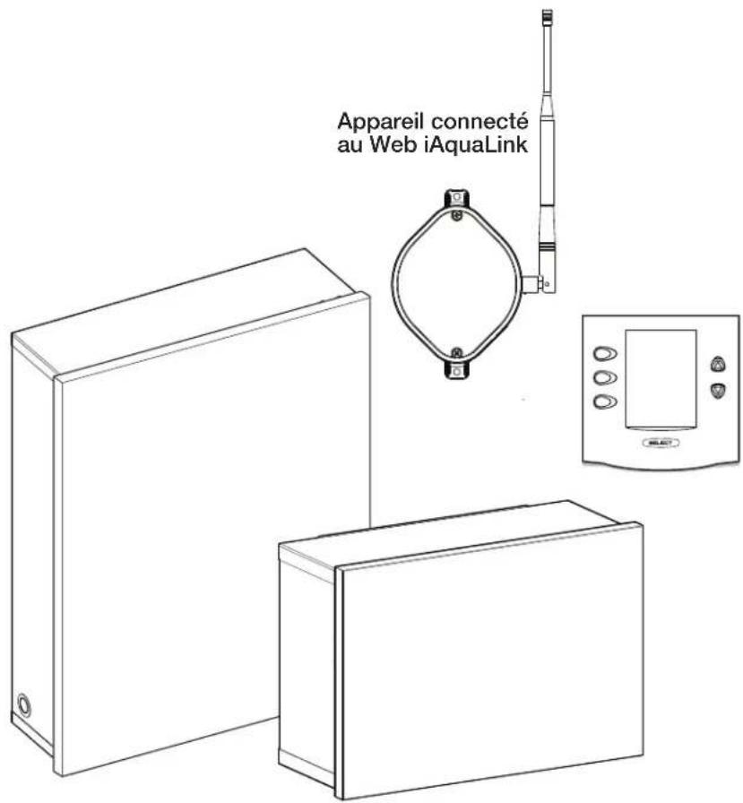
3.10 iAquaLink Web-Connected Device Installation
The iAquaLink device can be installed outdoors, on the equipment pad, or inside your home with a choice of wired or wireless connection.
The wireless iAquaLink device will transmit through walls and around corners. The transceivers do not require line of sight to communicate. Steel framing, aluminum siding, wrought iron, cyclone fences, leaded glass, and other 2.4 GHz frequency items may inhibit/prevent communication between the iAquaLink J-Box and the WiFi Access Point.
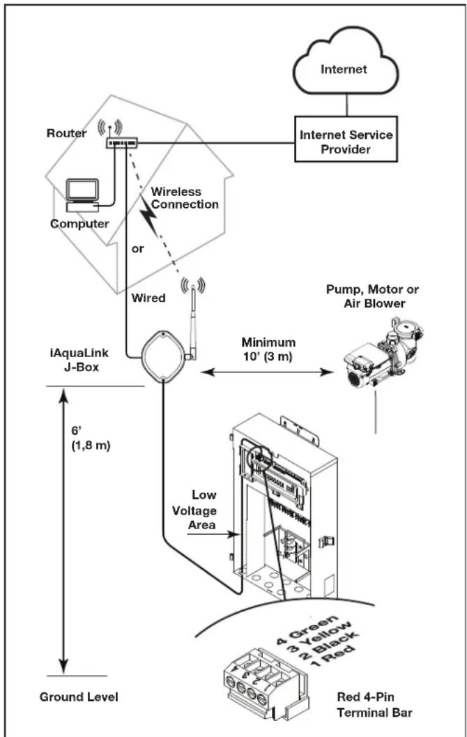
3.10.1 Outdoor Installation
WARNING
Potentially high voltages in the power center can create dangerous electrical hazards, possibly causing death, serious injury or property damage. Turn off power at the main circuit feeding the power center to disconnect the power center from the system.
Never run high voltage and low voltage in the same conduit.
- Turn off all power to the power center.
- Mount the outdoor iAquaLink J-box at least six (6) feet (1,8 m) above the ground, at least ten (10) feet (3 m) from any motor or air blowers that may be in the vicinity, and at least five (5) feet (1.5 m) away from other transceiver J-boxes. See Figure 31.
NOTE To improve performance of the transceiver, mount the iAquaLink device more than six (6) feet (1.8 m) above the ground. - Open the door to the power center and remove the dead panel.
- Pull cable through a knockout and into the low voltage area.
- Strip back the insulation jacket of the cable approximately 6" (15 cm).
- Strip each wire 14 " (6 mm) and connect to the red, wire connector on the power center PCB. A multiplex kit (P/N 6584) may be required if there are more than two (2) cables running to a red, wire connector on the PCB.
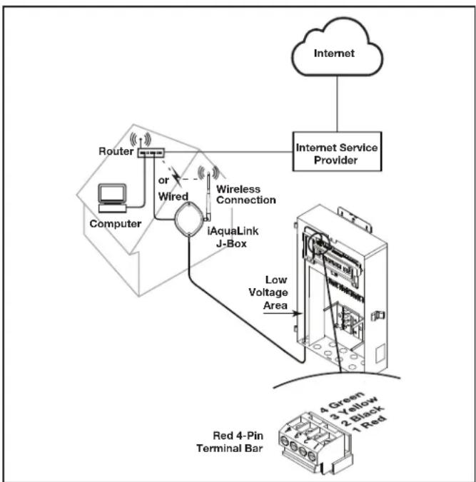
3.10.2 Indoor Installation

WARNING
Potentially high voltages in the power center can create dangerous electrical hazards, possibly causing death, serious injury or property damage. Turn off power at the main circuit feeding the power center to disconnect the power center from the system.
NOTE When installing the iAquaLink device indoors, if another AquaLink wired interface (ie. OneTouch™, All-button, etc.) is mounted indoors, the two devices may share an RS-485 (4-wire) cable to communicate from inside the home to the AquaLink control panel. In this scenario, the RS-485 cable from the iAquaLink device should be connected to the red 4-wire connector in the back of the wired interface. The red 4-wire connector will then have two cables running to it: the cable from the iAquaLink device, and the cable that runs to the AquaLink system on the equipment pad.
flowchart
graph TD
    A["Internet Service Provider"] --> B["Internet"]
    B --> C["Router"]
    C --> D["Computer"]
    D --> E["iAquaLink J-Box"]
    E --> F["Pump, Motor or Air Blower"]
    F --> G["Low Voltage Area"]
    G --> H["Red 4-Pin Terminal Bar"]
    H --> I["Ground Level"]
    E --> J["6' (1,8 m)"]
    J --> K["Wireless Connection or Wired"]
    K --> E
    style A fill:#f9f,stroke:#333
    style B fill:#ccf,stroke:#333
    style C fill:#cfc,stroke:#333
    style D fill:#fcc,stroke:#333
    style E fill:#cff,stroke:#333
    style F fill:#ffc,stroke:#333
    style G fill:#cfc,stroke:#333
    style H fill:#fcc,stroke:#333
    style I fill:#ffc,stroke:#333
Figure 30. iAquaLink J-Box Outdoor Installation
Never run high voltage and low voltage in the same conduit.
- Turn off all power to the power center.
- Find a suitable place inside your home to mount the iAquaLink device.
- Install the iAquaLink device at least six (6) feet (1.8 m) above the ground and at least five (5) feet (1.5 m) away from other transceiver J-boxes.
NOTE To improve performance of the iAquaLink device, you may wait to permanently mount it after it has been powered up. The signal strength indicator shown during the WiFi Hotspot method is a convenient way to determine & optimize signal strength between the iAquaLink device and the router.
- Open the door to the power center and remove the dead panel.
- Pull cable through the knockout and into the low voltage area. See Figure 31.
- Strip back the insulation jacket of the cable approximately 6" (15 cm).
- Strip each wire 14 " (6 mm) and connect to the red, wire connector on the power center PCB. A multiplex kit (P/N 6584) may be required if there are more than two (2) cables running to a red, wire connector on the power center PCB.
flowchart
graph TD
    A["Internet Service Provider"] --> B["Router"]
    B --> C["Computer"]
    C --> D["or Wired"]
    D --> E["iAquaLink J-Box"]
    E --> F["Low Voltage Area"]
    F --> G["Red 4-Pin Terminal Bar"]
    H["4 Green 3 Yellow 2 Black 1 Red"] --> G
Figure 31. iAquaLink J-Box Indoor Installation
3.10.3 Set Up the iAquaLink Device for Wireless Connection
There are 2 ways to do this, the Hotspot Method and the WPS Method.
For wired connection skip to Section 4.5
Connect iAquaLink to the Home Network - WiFi Hotspot Method
- Remove the two (2) screws from the cover of the iAquaLink J-box. Remove the gasket and cover. See Figure 32.
- Inside the iAquaLink, toggle the WiFi - Wired switch to clear the Wi-Fi settings and put the iAquaLink in desired setup mode.
-
After clearing the WiFi settings and with the Wired/WiFi switch set to WiFi, use a smartphone or WiFi enabled device and go to WiFi settings. Connect to the network labeled iAquaLink, followed by the last three digits of the iAquaLink device number. For example, iAquaLink ABC, if the last 3 digits of the device were ABC.
-
Locate the device number on the side product label or the door hanger that came with the device
-
Some devices will automatically re-direct you to the Log In Screen. If not, open a browser and go to any web page, such as zodiacpoolsystems.com
-
iAquaLink will display the networks it detects, as well as signal strength. Select the network iAquaLink should use.
NOTE If prompted for a password, enter the password for the home network (caps sensitive). iAquaLink will disconnect from the smartphone at this point.
- Within 2 minutes, the yellow LED should turn solid yellow, indicating it is communicating with the router. When the green LED illuminates, the iAquaLink is connected.
Connect iAquaLink to the Home Network - WPS (WiFi Protected Setup) Method
- Remove the two (2) screws from the cover of the iAquaLink J-box. Remove the gasket and cover. See Figure 32.
- Push the WPS Button on the pool owner's router. To find it, look for the ⬆ symbol or see the following notes.
NOTE Some brands use other names (like Quick Setup) or other icons (such as padlock or similar) for WPS. Some routers may have WPS disabled, which may require using the hotspot method. The hotspot method is recommended for Apple routers
-
Inside the iAquaLink, toggle the WiFi - Wired switch to clear the Wi-Fi settings and put the iAquaLink in desired setup mode.
-
After clearing the WiFi settings and with the Wired/WiFi switch set to WiFi, press and release the WPS button on the iAquaLink and wait for the small yellow LED, next to the WPS button to start blinking slowly.
-
Within 2 minutes, the yellow LED should stop blinking, and the green LED will illuminate. The iAquaLink is now connected.
For additional assistance, contact our Technical Support Department at 1-800-822-7933.
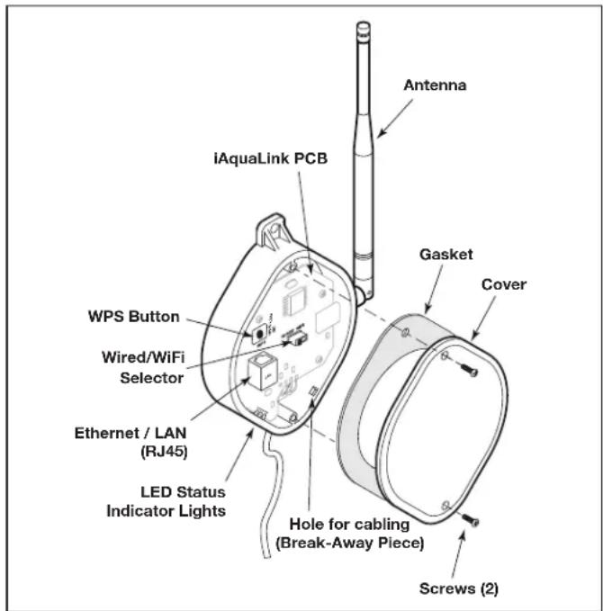
Figure 32. iAquaLink Device PCB Components
3.10.4 Set Up the iAquaLink Device for Wired Connection
NOTE To prevent potential Ethernet signal interference, order and install part# R0616800. (Does not apply to wi-fi installations).
- Remove the two (2) screws that secure the cover and gasket on the iAquaLink device. Remove the gasket and cover. See Figure 33.
- Slide the Wired/WiFi switch to the WIRED position.
- To allow the cable to exit the device, use needle nose pliers to remove the break-away piece. Wrap the cable inside the J-box and route it through the break-away hole.
- Using an Ethernet (RJ45) cable connect the iAquaLink device to the homeowner's router.
- Reinstall the cover and gasket on the iAquaLink J-box with the two (2) screws previously removed.
3.11 Powered Hardware Connection Test:
- When installation is complete and safe, turn power On at the breakers to restore power for the RS system and any attached peripheral equipment.
- Verify that all LEDs in the Power Center are on.
- Verify that all connected peripheral equipment are connected and on.
- Verify that the OneTouch Control Panel and/or the iAquaLink Web-connected Device are connected and on. All LEDs should show Green.
- Refer to the RS Control System Owner's Manual, as well as the specific equipment Owner's manual, for further details on programming all connected peripheral equipment.
3.12 Further Reference Information
For RS programming and operation, please refer to the AquaLink RS Control System Owner's Manual (P/N H0812100 Rev A) located at www.jandy.com under the Residential Automation RS Section.
Section 4. Troubleshooting
4.1 OneTouch Quick Troubleshooting Guide
| Symptom Problem | Possible Solution | |
| Power center override switches operate when in service or time out mode, but the control panel is completely dead (no lights on, no display). | Power supply problem. Check connection of the outside two wires (red & green) of the four conductor cable. If wired correctly, check the voltage between these two wires. Voltage for an All button system should be 7+ VDC and for a OneTouch system, 8+ VDC (use the higher voltage for a mixed system). | |
| All LEDs are on at the control panel and the part # and revision letter of the control panel software are displayed. The override switches at the power center operate as they should. | Control panel is not communicating with the power center PCB. | Check the two center wires (black & yellow) of the four conductor cable. Also check the installation of the CPU Board on the power center PCB. If the PPD is not seated correctly the system will not communicate. |
| All LEDs are on at the control panel and the part # and revision letter are displayed, but override switches at the power center do not operate at all. | 1. Damaged or improperly installed CPU Board.2. Damaged power center PCB. | 1. Check alignment of the CPU Board.2. If CPU Board is installed correctly, replace the power center PCB. |
| Some buttons do not operate from the control panel, nor from the power center override switches. | Wrong CPU Board chip installed at the power center PCB. | Check part number and revision letter by pressing the reset button at the control panel. The second part number and revision letter displayed is for the CPU Board indicating which model. |
| System locked up. Microprocessor locked. Turn off power to the system and turn back on. | ||
| Programs do not run at the correct time. | AquaLink does not display correct time and date. | At the control panel set correct time and date. |
| One button on the Four Function Remote or SpaLink® RS does not operate. | Check programming first. If the Four Function Remote or SpaLink RS is programmed correctly, the button may be shorted. | Replace the Four Function Remote or SpaLink RS. Use MENU, REVIEW, SPA SWITCH (or SPA LINK) to check programming. |
| Pool cleaner booster pump turns on without the filter pump being on, and can run with the spa on. | System is not recognizing DIP switch S1-1 is on. Note: before turning on any DIP switches, first turn off all equipment. | Turn off all equipment buttons, then turn off power to the system, finally turn off, then on, DIP switch S1-1. Turn on power and test system. |
| Symptom Problem P | Possible Solution | |
| Model is one of the AquaLink RS Dual Equipment, message scrolls "ADJUSTABLE FREEZE SENSOR NOT INSTALLED".System comes on at times that are not programmed. | Normal operation when a Dual Equipment AquaLink RS is controlling a solar system and an adjustable freeze sensor is not installed. | Either install the adjustable freeze sensor, or wait 24 hours and this message will go away. |
| System comes on at times that are not programmed. | Phantom programs. At the control panel press MENU, then scroll to REVIEW. Make note of all programs (the Four Function Remote setting, labels, and temperature settings) then turn off all DIP switches and go to the control panel. CLEAR MEMORY, reprogram and try system again. | |
| Heater will not fire. Heater LED will not light in "Service Mode". | Water temperature sensor not installed or defective. | Check water temperature sensor. |
4.2 iAquaLink Troubleshooting Guide
Use the troubleshooting information in the following table for suggestions.
| Symptom Problem | Possible Solution | |
| The iAquaLink is on and the startup screen is displayed. The override switches at the power center operate as they should. | The iAquaLink is not communicating with the power center PCB. | Check the cabling to the iAquaLink Web-Connect device (all conductors). |
| The iAquaLink is on and the "Waiting for connection..." screen is displayed, but override switches at the power center do not operate at all. | 1. Damaged or improperly installed CPU board.2. Wrong CPU board.3. Damaged power center PCB. | 1. Check alignment of the CPU board.2. Make sure that the CPU board is revision R or later for an AquaLink RS system. Make sure that the CPU board is revision 6.0 or later for PDA control system.3. If CPU board is installed correctly, replace the power center PCB. |
| Some buttons do not operate from the iAquaLink, nor from the power center override switches. | Wrong CPU board installed at the power center PCB. | Make sure that the CPU board is revision R or later for an AquaLink RS system. Make sure that the CPU board is revision 6.0 or later for PDA control system. |
| Programs do not run at the correct time. | The iAquaLink does not display correct time and date. | At the iAquaLink screen, set correct time and date. |
| Communication is lost. | Signal Interference. | The wireless iAquaLink J-box will stop communicating anytime interference (such as a 2.4 GHz device) prevents a valid signal transmission. When communication is lost the iAquaLink screen will lock on the "waiting for connection..." screen until a good link is again achieved, usually within a few seconds. |
4.3 LED Status Indicator Lights
Normal Operating Mode
| Function LED Indication | |
| Power (Red) ON | = PowerOFF = No power |
| Network Connection* (Yellow) | ON = Connected to NetworkFast Flashing = CommunicationSlow Flashing/OFF = Not connected |
| Online Status** (Green) | ON = On-Line (connected to internet)OFF = Off-Line |
* Network Connection: the connection between the iAquaLink device and the Wi-Fi access point (ie. wires router)
** Online Status: the connection to the internet. Only possible when Yellow LED indicates the iAquaLink is already connected or communicating to the router.
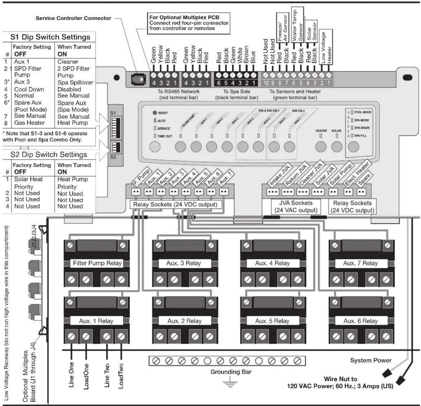
Section 5. Power Center Wiring Diagram for Combos and Onlys
flowchart
graph TD
    A["Service Controller Connector"] --> B["S1 Dip Switch Settings"]
    B --> C["Factory Setting OFF"]
    B --> D["When Turned ON"]
    B --> E["To RS485 Network (red terminal bar)"]
    B --> F["To Spa Side (black terminal bar)"]
    B --> G["To Sensors and Heater (green terminal bar)"]
    B --> H["Reset AUTO SERVICE TIME OUT"]
    B --> I["RS6 & RSE ONLY AUX 1-7"]
    B --> J["RELay Sockets (24 VDC output)"]
    B --> K["JVA Sockets (24 VAC output)"]
    B --> L["RELay Sockets (24 VDC output)"]
    M["Low Voltage Raceway (J1 through J4)"] --> N["Optional Multiplex Board"]
    M --> O["Line One LoadOne Line Two LoadTwo"]
    P["For Optional Multiplex PCB Connect red four-pin connector from controller or remotes"] --> Q["Green Yellow Black Red Green Yellow Black Red Red Black Green White Brown Blue Not Used Not Used Red Black Red Black Red Low Voltage Heater"]
    P --> R["Freeze/Air Sensor Water Temp. Sensor Solar Sensor Low Voltage Heater"]
    S["S2 Dip Switch Settings"] --> T["Factory Setting OFF"]
    S --> U["When Turned ON"]
    S --> V["Solar Heat Priority Not Used Not Used Not Used"]
    W["S1"] --> X["To RS485 Network (red terminal bar)"]
    W --> Y["To Spa Side (black terminal bar)"]
    W --> Z["To Sensors and Heater (green terminal bar)"]
    AA["Relay Sockets (24 VDC output)"] --> AB["Filter Pump Relay"]
    AA --> AC["Aux. 3 Relay"]
    AA --> AD["Aux. 4 Relay"]
    AA --> AE["Aux. 7 Relay"]
    AA --> AF["Aux. 1 Relay"]
    AA --> AG["Aux. 2 Relay"]
    AA --> AH["Aux. 5 Relay"]
    AA --> AI["Aux. 6 Relay"]
    AA --> AJ["Grounding Bar"]
    AK["Power Supply"] --> AL["Water Temp. Sensor"]
    AK --> AM["Solar Sensor"]
    AK --> AN["SPA MODE"]
    AK --> AO["SPA DRAIN"]
    AK --> AP["SPA FILL"]
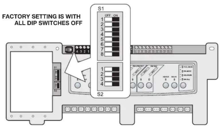
Section 6. Power Center PCB DIP Switch Settings
6.1 DIP Switch Functions
S1 DIP #1 ON- AUX 1 Controls Pool Cleaner
If you installed a booster pump for a pool cleaner, the relay coil for the booster pump must be plugged into the AUX 1 relay socket. If a non-booster pump cleaner is installed, plug the JVA into the cleaner JVA socket. Turn ON DIP Switch #1.
- Main filter pump turns on whenever cleaner turns on.
- Cleaner will not turn on until filter pump has been on for three (3) minutes (to ensure priming of system).
- Cleaner turns off when water circulation is to spa.
- Cleaner turns off when spa spillover feature is activated.
- Cleaner turns off for three (3) minutes when solar is activated (to ensure air is purged from the system).
- AquaLink RS control panel display reads "CLEANER" rather than "AUX 1".
S1 DIP #2 ON- AUX 2 Controls Low Speed of Filter Pump
Turn this switch ON if you want to control both speeds of a two-speed filter pump. With this switch on, the filter pump button on the AquaLink RS control panel will control high speed and the AUX 2 button will control low speed.
IMPORTANT You must also install a Jandy two-speed relay.
S1 DIP #3 ON- AUX 3 Controls Spa Spillover (Operates with Pool/Spa Combination)
Turn this switch ON, and when the AUX 3 button on the AquaLink RS control panel (or spa side switch) is pressed, the return valve actuator will rotate to spa circulation. Because the intake valve actuator does not rotate, the spa will fill with water and overflow into the pool.
NOTE Leave AUX 3 relay socket empty.
S1 DIP #4 ON- Heater Cool Down Disabled
Turn this switch ON to disable the heater cool down safety feature on the AquaLink RS.
WARNING
Turn this DIP Switch ON only if you are using an electric heater or a heat pump that does not retain residual heat. If you are turning this switch ON for service purposes, be sure to turn it back off to ensure that equipment operates as specified.
S1 DIP #5 ON- Factory Use Only
This switch is used for calibration by Jandy® certified technicians only. Please leave this switch in the OFF position.
S1 DIP #6 ON
Change spare AUX to activate when filter pump is on and system is in spa mode (pool/spa combination units only). Spare AUX socket is on the front side of the power center PCB.
S1 DIP #7 ON- Not Used
This switch only applies to DUAL EQUIPMENT systems. When OFF a separate heater is used for the pool and spa. When ON the pool and spa share the same heater.
S1 DIP #8 ON- Heat Pump Instead of Gas Heater
Turn this switch ON if you have installed a heat pump instead of a gas heater. After thermostat setting has been reached, heater will remain OFF for 5 minutes.
S2 DIP #1 ON- Heat Pump Priority
This switch is used for configuring solar priority or heat pump priority. Set this switch to ON if heat pump priority will be used. Set this switch to OFF if solar priority is to be used.
6.2 DIP Switch Settings for Pool and Spa Combination
| S1 DIP Switch # OFF ON | ||
| 1 AUX1= any equipment AUX1= Pool Cleaner | ||
| 2 AUX2= any equipment AUX2= Low Speed for a two-speed filter pump.Filter pump circuit becomes High Speed. | ||
| 3 AUX3= any equipment AUX3= Spa Spillover effect- Combination controls only. | ||
| 4 Heater cool down operates. Heater cool down disabled. | ||
| 5 Normal operation Factory adjustment- when this switch is on, temperature delays are eliminated and solar temperature is displayed.Do not leave this switch in the ON position. | ||
| 6 Spare Aux activates with Filter Pump when Spa OFF. | No change on Revision "HH" or older PPD. With revision "I" or newer, Spare AUX operation is reversed. | |
| 7 Spare No change on Combination or Only Controls. | ||
| 8 After thermostat setting has been reached, heater will remain OFF for three (3) minutes. | Heat Pump installed; after thermostat setting has been reached, heater will remain OFF for five (5) minutes. | |
| S2 DIP Switch # OFF ON | ||
| 1 The AquaLink RS will be able to control a Solar Heating system (If a solar sensor is connected to the solar sensor input). | The AquaLink RS will be able to control a Heat Pump. (The AquaLink RS will not be able to control a Solar Heating system.) | |
| 2 NOT USED | ||
| 3 NOT USED | ||
| 4 NOT USED | ||
6.3 DIP Switch Settings for Pool or Spa Only
| S1 DIP Switch # OFF ON | ||
| 1 AUX1= any equipment AUX1= Pool Cleaner | ||
| 2 AUX2= any equipment AUX2= Low Speed for a two-speed filter pump. | ||
| Filter pump circuit becomes High Speed. | ||
| 3 AUX3= any equipment No change | ||
| 4 Heater cool down operates. Heater cool down disabled. | ||
| 5 Normal operation Factory adjustment- when this switch is on, temperature delays are eliminated and solar temperature is displayed.Do not leave this switch in the ON position. | ||
| 6 Spare No change | ||
| 7 Spare No change | ||
| 8 After thermostat setting has been reached, heater will remain OFF for 3 minutes. | Heat Pump installed; after thermostat setting has been reached, heater will remain OFF for 5 minutes. | |
| S2 DIP Switch # OFF ON | |
| 1 The AquaLink RS will be able to control a Solar Heating system (If a solar sensor is connected to the solar sensor input). | The AquaLink RS will be able to control a Heat Pump. (The AquaLink RS will not be able to control a Solar Heating system.) |
| 2 NOT USED | |
| 3 NOT USED | |
| 4 NOT USED | |
6.4 DIP Switch Settings for Heat Pump Installation
This table shows how to configure the system for SOLAR PRIORITY or HEAT PUMP PRIORITY.
| DIP S2-1 | GREEN 10-PIN TERMINAL BAR | RS485 HEAT PUMP DESCRIPTION |
| OFF No | sensor installed Not connected In this configuration | there is no Solar Heating and no Heat Pump. Extra AUX is available. |
| OFF Sensor | installed Not connected In this configuration | there is Solar Heating and there is Solar Priority. There is no Heat Pump. |
| OFF Sensor | installed Connected In this configuration there | is Solar Heating and there is Solar Priority. There is Heat Pump. There is Heat Pump Priority. |
| ON No | sensor installed Not connected In this configuration | there is no Solar Heating. There is a mechanically connected Heat Pump. There is Heat Pump Priority (a limited implementation). |
| ON Sensor | installed Not connected In this configuration there | there is no Solar Heating. There is a mechanically connected Heat Pump. There is Heat Pump Priority (full implementation). |
| ON Sensor | installed Connected In this configuration there | is no Solar Heating. There is an RS485 controlled Heat Pump. There is Heat Pump Priority. |
NOTES
Zodiac Pool Systems LLC
2882 Whiptail Loop # 100
Carlsbad, CA 92010, USA
Jandy.com | 1.800.822.7933
Zodiac Pool Systems Canada, Inc.
2-3365 Mainway
Burlington, ON L7M 1A6, Canada
Jandy.ca | 1.800.822.7933
A Fluidra Brand
©2023 Zodiac Pool Systems LLC. All rights reserved. ZODIAC * is a registered trademark of Zodiac International,
S.A.S.U., used under license. All other trademarks are the property of their respective owners.
6594_REVU

Intertek
ETL Listed
Conforms to UL STD 1563
Certified to CSA STD C22.2 No. 218.1

Section 3. Installation....42
Incandescent 1 500 watts
natural_image
Technical line drawing of a mechanical device with hoses and a central shaft (no text or symbols)Section 3. Installation
natural_image
Pure electrical circuit lines without any symbolsZodiac Pool Systems LLC
2882 Whiptail Loop # 100
Carlsbad, CA 92010, USA
Jandy.com | 1.800.822.7933
Zodiac Pool Systems Canada, Inc.
2-3365 Mainway
Burlington, ON L7M 1A6, Canada
Jandy.ca | 1.800.822.7933
Une marque Fluidra
natural_image
Technical line drawing of a mechanical device with a cylindrical component and a rod (no text or symbols)Zodiac Pool Systems LLC
2882 Whiptail Loop # 100
Zodiac Pool Systems Canada, Inc.
2-3365 Mainway
Jandy.ca | 1.800.822.7933
Una marca Fluidra
- AquaLink® RS Control Systems
- WARNING
- Table of Contents
- Section 1. Important Safety Instructions .....3
- Section 2. System Overview ...... 5
- Section 3. Installation....8
- Section 4. Troubleshooting....25
- Section 5. Power Center Wiring Diagram for Combos and Onlys .....28
- Section 6. Power Center PCB DIP Switch Settings....29
- EQUIPMENT INFORMATION RECORD
- Section 1. Important Safety Instructions
- READ AND FOLLOW ALL INSTRUCTIONS
- Safety Instructions
- To Reduce the Risk of Injury -
- FCC Regulatory Compliance Statement
- SAVE THESE INSTRUCTIONS
- Section 2. System Overview
- System Component Specifications and Dimensions
- Specifications (USA and Canada)
- Dimensions
- Basic Plumbing
- Plumbing for Pool and Spa Combination
- Booster Pump Pool Cleaner Plumbing
- Non-Booster Pump Pool Cleaner Plumbing
- Section 3. Installation
- Power Center Mounting
- High Voltage Wiring
- System Power
- 3HP (Standard) Relays
- Bonding the Power Center
- High Voltage Underwater Lighting GFCI Wiring
- CAUTION
- Jandy Pool and Spa Lights Wiring
- Infinite Watercolors Nicheless LED Light
- RISK OF ELECTRICAL SHOCK OR ELECTROCUTION,
- Wire Gauge and Length
- Fourteen (14) Volt Installation
- RS-485 Connection
- Variable Speed Pump Wiring (High Voltage)
- Jandy Variable Speed Pump
- Pentair® Variable Speed/Flow Pumps
- Low Voltage Wiring
- Bezel Connection
- Control Panel Cable to Power Center PCB
- Variable Speed Pump to Power Center PCB Cable
- Wiring the Jandy Variable Speed Pump
- Jandy Variable Speed Pump DIP switch settings
- Dipswitch Settings with Local Controller
- Dip Switch Settings with Automation
- Pre-2022 Aqualink RS Firmware Rev\_V and Earlier
- Aqualink RS Firmware Rev W and Later
- Wiring the Pentair ® Pump
- Heater Connection
- Jandy Heater Connections
- Guidelines for Sophisticated Diagnostic Communication to Jandy JXi™ Heaters
- Other Brands Heater and Pump Connections
- Guidelines for a Gas Heater and a Heat Pump/Chiller Installation
- Temperature Sensors
- Jandy Valve ® Actuators
- Jandy TruSense Water Chemistry Analyzer
- Auxiliary Power Centers
- NOTE
- OneTouch Control Panel Indoor Installation
- Surface Mount OneTouch Indoor Installation
- Flush Mount OneTouch Indoor Installation
- Multiple AquaLink RS OneTouch Control Panel Indoor Installation
- AquaLink RS OneTouch Control Panel Jumper Settings
- iAquaLink Web-Connected Device Installation
- Outdoor Installation
- Indoor Installation
- Set Up the iAquaLink Device for Wireless Connection
- Connect iAquaLink to the Home Network - WiFi Hotspot Method
- Connect iAquaLink to the Home Network - WPS (WiFi Protected Setup) Method
- Set Up the iAquaLink Device for Wired Connection
- Powered Hardware Connection Test:
- Further Reference Information
- Section 4. Troubleshooting
- iAquaLink Troubleshooting Guide
- LED Status Indicator Lights
- Section 6. Power Center PCB DIP Switch Settings
- DIP Switch Functions
- S1 DIP #1 ON- AUX 1 Controls Pool Cleaner
- S1 DIP #2 ON- AUX 2 Controls Low Speed of Filter Pump
- S1 DIP #3 ON- AUX 3 Controls Spa Spillover (Operates with Pool/Spa Combination)
- S1 DIP #4 ON- Heater Cool Down Disabled
- S1 DIP #5 ON- Factory Use Only
- S1 DIP #6 ON
- S1 DIP #7 ON- Not Used
- S1 DIP #8 ON- Heat Pump Instead of Gas Heater
- S2 DIP #1 ON- Heat Pump Priority
- DIP Switch Settings for Heat Pump Installation
- NOTES
- Section 3. Installation....42
Brand : Jandy
Model : AquaLink RS All Button
Category : Electronic control system