
PAC - Controller POLARIS - Free user manual and instructions
Find the device manual for free PAC POLARIS in PDF.
| Product Type | Pool/Spa Automation Controller |
| Brand | Polaris |
| Model | PAC |
| Power Supply | 120 V AC, 60 Hz, 1.67 A |
| High Voltage Contact Rating | 15 A max, 1.5 HP at 120 V AC |
| Number of Auxiliary Relays | 3 (Aux 1, Aux 2, Aux 3) |
| Outputs | 1 filter pump, 3 auxiliary (including chlorinator, light transformer) |
| Sensor Inputs | Water temperature, air temperature, solar sensor (optional) |
| Communication | RS-485 for iAquaLink™ and other devices |
| Number of Timer Programs | Up to 10 combinations (on/off) |
| Display | Backlit LCD with menus |
| Freeze Protection | Yes, adjustable from 34 °F to 42 °F (1 °C to 6 °C) |
| Dimensions (approx.) | 20 cm x 15 cm x 8 cm (estimate) |
| Weight (approx.) | 1.5 kg (estimate) |
| Operating Temperature | -10 °C to 50 °C |
| Protection Rating | IPX4 (estimate) |
| Safety | GFCI/ELCB protection required, grounding, interlocks |
| Maintenance | Regularly check sensors, keep housing clean and dry |
| Spare Parts | Sensors, mounting brackets, cables (contact customer service) |
| Certifications | ETL, UL Std 1563, CSA C22.2 No. 218.1 |
| Warranty | Manufacturer warranty (see terms) |
Frequently Asked Questions - PAC POLARIS
User questions about PAC POLARIS
0 question about this device. Answer the ones you know or ask your own.
Ask a new question about this device
Download the instructions for your Controller in PDF format for free! Find your manual PAC - POLARIS and take your electronic device back in hand. On this page are published all the documents necessary for the use of your device. PAC by POLARIS.
USER MANUAL PAC POLARIS
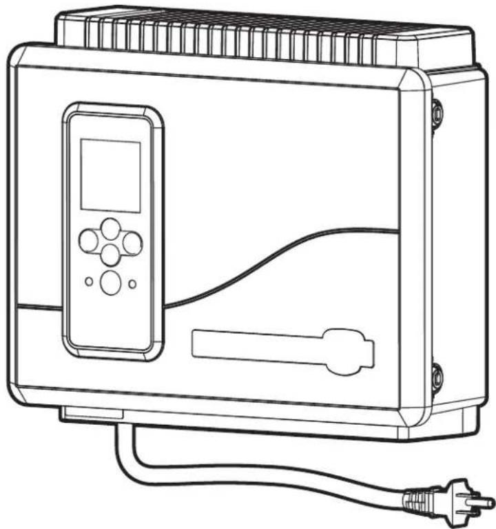
natural_image
Line drawing of a portable electronic device with control panel, power cord, and plug (no text or symbols)Above-Ground
Pool Automation Control
PAGAUT
Owner's Manual
English | Français | Español
WARNING
FOR YOUR SAFETY - This product must be installed by a qualified pool professional or personnel who are knowledgeable with the standards and code requirements for above ground pool equipment. The maintainer must be a qualified pool professional or personnel with sufficient experience in pool equipment installation and maintenance so that all of the instructions in this manual can be followed exactly.
Improper installation and/or operation may result in death, serious injury or property damage. DO NOT MODIFY THIS EQUIPMENT.

Before installing this product, read and follow all warning notices and instructions that accompany this product. Failure to follow warning notices and instructions may result in death, serious injury or property damage. Consult Polaris customer service at 1-800-822-7933 for assistance. Improper installation and/or operation may void the warranty.
Table of Contents
Section 1. Important Safety Instructions....3
Section 2. System Overview....5
2.1 Package Contents....5
2.2 Electrical Specifications 5
2.3 Materials and Tools 5
Section 3. Install Controller Box ....5
3.1 Mount the Controller Enclosure 5
3.2 Bonding the Power Center 6
Section 4. High Voltage Plug In....6
4.1 Plug In Assignment 6
Section 5. Low Voltage Wiring....6
5.1 Wire the Temperature Sensors 6
5.2 Install the Water Temperature Sensor....6
5.3 Install a Solar Sensor (if applicable) 7
5.4 Install Additional Low Voltage Equipment (i.e., Heater Connection) 7
5.5 Install iAquaLink ™ (if applicable) 7
5.6 Mount the iAquaLink Device 7
5.7 Wire the iAquaLink Device....7
5.8 Install Jandy Valve ^® Actuators (JVAs) (if applicable) 7
Section 6. User Interface....7
6.1 Navigation Buttons....7
Section 7. Install Settings....8
7.1 Freeze Protect 8
7.2 Units 9
7.3 Languages 9
7.4 Clear Memory 9
7.5 Color Lights....9
7.6 Label Auxiliary Functions 10
7.7 Temp Calibrate....10
7.8 Solar Priority (if applicable)....10
7.9 Assign JVA....10
7.10 Diagnostics 11
Section 8. Main Menu....12
8.1 Equipment Status.... 12
8.2 Filter Pump....12
8.3 Pool Heater On/Off 12
8.4 Turn Aux1, Aux2 or Aux3 On/Off 12
8.5 Turn Specific Equipment On/Off Manually 13
8.6 Turn All Equipment Off 14
Section 9. Pool Only System Menu Flow Diagrams....15
9.1 Main Menu 15
9.2 Install Settings Menu.... 16
Section 10. Glossaries ....17
10.1 Glossary of Safety Delays and Lockouts 17
10.2 Glossary of Alert Messages 17
Section 11. Wiring Diagram....18
FCC Regulatory Compliance Statement
This device complies with Part 15 of the FCC Rules. Operation is subject to the following two conditions:
- This device may not cause harmful interference, and
- This device must accept any interference received, including interference that may cause undesired operation/
CAUTION: Changes or modifications not expressly approved by the party responsible for compliance may void the user's authority to operate the equipment.
NOTE: This equipment has been tested and found to comply with the limits for a Class B digital device, pursuant to Part 15 of the FCC Rules. These limits are designed to provide reasonable protection against harmful interference in a residential installation. This equipment generates, uses and can radiate radio frequency energy and, if not installed and used in accordance with the instructions, may cause harmful interference to radio communications. However, there is no guarantee that interference will not occur in a particular installation. If this equipment does cause harmful interference to radio or television reception, which can be determined by turning the equipment off and on, the user is encouraged to try to correct the interference by one or more of the following measures:
- Reorient or relocate the receiving antenna.
- Increase the separation between the equipment and receiver.
- Connect the equipment into an outlet on a circuit different from that to which the receiver is connected.
- Consult the dealer or an experienced radio/TV technician for help.
Section 1. Important Safety Instructions
READ AND FOLLOW ALL INSTRUCTIONS
All electrical work must be performed by a licensed electrician and conform to all national, state, and local codes. When installing and using this electrical equipment, basic safety precautions should always be followed, including the following:

DANGER
To reduce the risk of severe injury or death, do not remove the suction fittings of your spa or hot tub. Never operate a spa or hot tub if the suction fittings are broken or missing. Never replace a suction fitting with one rated less than the flow rate marked on the equipment assembly.

WARNING
Prolonged immersion in hot water may induce hyperthermia. Hyperthermia occurs when the internal temperature of the body reaches a level several degrees above the normal body temperature of 98.6^ F ( 37^ C). The symptoms of hyperthermia include dizziness, fainting, drowsiness, lethargy, and an increase in the internal temperature of the body. The effects of hyperthermia include: 1) unawareness of impending danger; 2) failure to perceive heat; 3) failure to recognize the need to exit spa; 4) physical inability to exit spa; 5) fetal damage in pregnant women; 6) unconsciousness resulting in a danger of drowning. The use of alcohol, drugs, or medication can greatly increase the risk of fatal hyperthermia.

WARNING
To Reduce the Risk of Injury
a) The water in a spa should never exceed 104^ F ( 40^ C). Water temperatures between 100^ F ( 38^ C) and 104^ F ( 40^ C) are considered safe for a healthy adult. Lower water temperatures are recommended for young children and when spa use exceeds 10 minutes.
b) Since excessive water temperatures have a high potential for causing fetal damage during the early months of pregnancy, pregnant or possibly pregnant women consult a physician before using a spa or hot tub, and should limit spa water temperatures to 100^ F ( 38^ C). Water temperature in excess of 100^ F ( 38^ C) may be injurious to your health.
c) Before entering a spa or hot tub, the user should measure the water temperature with an accurate thermometer since the tolerance of water temperature-regulating devices varies.
d) The use of alcohol, drugs, or medication before or during spa or hot tub use may lead to unconsciousness with the possibility of drowning.
e) Obese persons and persons with a history of heart disease, low or high blood pressure, circulatory system problems, or diabetes should consult a physician before using a spa.
f) Persons using medication should consult a physician before using a spa or hot tub since some medication may induce drowsiness while other medication may affect heart rate, blood pressure, and circulation.

WARNING
Risk of electric shock which could result in severe injury or death - Install the controller at least 2 ft. (0.6m) vertically off the ground and five (5) feet (1.52 m) from the inside wall of the pool and/or hot tub using non-metallic plumbing so children cannot use the equipment to access the pool and be injured or drown. Canadian installations must be at least three (3) meters from the water.
PREVENT CHILD DROWNING: Do not let anyone, especially small children, sit, step, lean or climb on any equipment installed as part of your pool's operational system.
Children should not use spas or hot tubs without adult supervision.
Do not use spas or hot tubs unless all suction guards are installed to prevent body and hair entrapment.
People using medications and/or having an adverse medical history should consult a physician before using a spa or hot tub.

WARNING
To avoid injury ensure that you use this control system to control only packaged pool/spa heaters which have built-in operating and high limit controls to limit water temperature for pool/spa applications. This device should not be relied upon as a safety limit control.
WARNING
People with infectious diseases should not use a spa or hot tub.
To avoid injury, exercise care when entering or exiting the spa or hot tub.
Do not use drugs or alcohol before or during the use of a spa or hot tub to avoid unconsciousness and possible drowning.
Pregnant or possibly pregnant women should consult a physician before using a spa or tub.
Water temperature in excess of 100^ F ( 38^ C) may be hazardous to your health.
Before entering a spa or hot tub, measure the water temperature with an accurate thermometer.
Do not use a spa or hot tub immediately following strenuous exercise.
Prolonged immersion in a spa or hot tub may be injurious to your health.
Do not permit any electric appliance (such as a light, telephone, radio, or television) within five (5) feet (1.52 m) of a spa or hot tub.
The use of alcohol, drugs or medication can greatly increase the risk of fatal hyperthermia in hot tubs and spas.
WARNING
A terminal bar marked "GROUND" is provided within the controller. To reduce the risk of electrical shock which can cause serious injury or death, connect this terminal bar to the grounding terminal of your electric service or supply panel with a continuous copper conductor having green insulation and one that is equivalent in size to the circuit conductors supplying this equipment, but no smaller than no. 12 AWG (3.3 mm ^2 ). In addition, a second wire connector should be bonded with a no. 8 AWG (8.4 mm ^2 ) copper wire to any metal ladders, water pipes, or other metal within five (5) feet (1.52 m) of the pool/spa. In Canada the bonding wire must be minimum 6 AWG (13.3 mm ^2 ).
WARNING
To reduce the risk of electric shock, fire or injury, service should only be attempted by a qualified pool service professional.
Risk of Electric Shock. Connect only to a branch circuit protected by a ground-fault circuit-interrupter (GFCI). (in Canada: CONNECT ONLY TO A CIRCUIT PROTECTED BY A CLASS A GROUND FAULT CIRCUIT INTERRUPTER) Contact a qualified electrician if you cannot verify that the circuit is protected by a GFCI.
Such a GFCI should be tested on a routine basis. (In Canada: TEST THE GROUND FAULT CIRCUIT INTERRUPTER BEFORE EACH USE OF THE SPA) To test the GFCI, push the test button. The GFCI should interrupt power. Push the reset button. Power should be restored. If the GFCI fails to operate in this manner, the GFCI is defective. If the GFCI interrupts power to this equipment without the test button being pushed, a ground current is flowing, indicating the possibility of an electric shock. Do not use this equipment. Disconnect this equipment and have the problem corrected by a qualified service representative before using.
Do not bury the cords. Locate cords to minimize abuse from lawn mowers, hedge trimmers, and other equipment.
To reduce the risk of electric shock, replace damaged cord immediately and do not use an extension cord to connect unit to electric supply; provide a properly located outlet.
This equipment is for use with permanently-installed pools only. Do not use with storable pools. A storable pool is constructed so that it is capable of being readily disassembled for storage and reassembled to its original integrity. A permanently-installed pool is constructed in or on the ground or in a building such that it cannot be readily disassembled for storage.
To reduce the risk of injury, do not permit children to use this product unless they are supervised at all times.
CAUTION
The conductors on the load side of the ground-fault circuit-interrupter shall not occupy conduit, boxes, or enclosures containing other conductors unless the additional conductors are also protected by a ground-fault circuit-interrupter. Refer to local codes for complete details. MAINTAIN WATER CHEMISTRY IN ACCORDANCE WITH MANUFACTURER'S INSTRUCTIONS.
Section 2. System Overview
2.1 Package Contents
- Four Function Controller
• Water Temperature Sensor Kit
• Air Temperature Sensor - Mounting Hardware
- Mounting Bracket
• Installation Manual/ Owner's Manual
2.2 Electrical Specifications
Power Supply 120 VAC; 60 Hz; 1.67 A
Contact Rating High voltage - 15 A;
1.5HP @ 120 VAC
1500 Watts Incandescent
Low Voltage - Class 2,
1 A @ 24 VAC
2.3 Materials and Tools
Installation Materials Furnished
- Screw Set (includes Plastic Anchors)
• Metal Mounting Bracket
Tools Needed for Installation
- Power Drill
- 3/16" Drill Bit - Hammer Drill Bit (only necessary to drill into brick or concrete)
- Pencil or Marking Pen
- Flat Head Screwdriver
• Phillips Head Screwdriver - Small Flathead or Slotted Screwdriver
• Protective Safety Eyewear - Protective Work Gloves
Section 3. Install Controller Box
WARNING
FOR YOUR SAFETY: This product must be serviced by a professional pool/spa service technician as described on the front cover of this manual. The procedures in this manual must be followed exactly.
Failure to follow warning notices and instructions may result in property damage, serious injury, or death. Improper installation and/or operation may void the warranty.
Risk of Electric Shock. Connect only to a branch circuit protected by a ground-fault circuit-interrupter (GFCI). Contact a qualified electrician if you cannot verify that the circuit is protected by a GFCI. To reduce the risk of electric shock, do not use extension cord to connect unit to electric supply; provide a properly located outlet.
CAUTION
To reduce the risk of electric shock do not place the power pack closer than 5 feet (1.5 m) from the pool. In Canada, at least 3 meters (10 feet) horizontally from the edge of the pool.
Do not bury the cords. Locate cords to minimize abuse from lawn mowers, hedge trimmers, and other equipment.
When mounting the controller box in the equipment pad, instructions must be followed exactly. Read through the Important Safety Information section completely before beginning installation and before operating the equipment.
Before you begin installation, make sure you have the necessary tools and a suitable location to install the automation system.
NOTE: The controller should be located at or near the equipment pad.
Locate the controller at least five (5) feet or more away from pool and two (2) feet (0.6m) off the ground. In Canada, at least 3 meters (10 feet) horizontally from the edge of the pool. All national, state, and local codes are applicable.
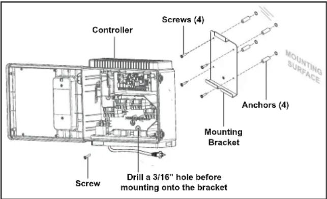
3.1 Mount the Controller Enclosure
- Using a flat screwdriver, rotate door tumblers counter-clockwise to unlock the front cover of the controller.
- Open the front cover door and remove the mounting hardware kit.
- Using the holes in the bracket as a guide, mark four (4) dots on the surface where the controller will be mounted. The four (4) mounting holes are 3-15/16" (10 cm) apart center to center.
NOTE: Make sure to mark out the four (4) holes as accurately as possible.
- Drill four (4) holes in the mounting surface.
-
Press the four (4) plastic anchors firmly into holes.
-
Screw the mounting bracket onto the mounting surface with the four (4) screws provided.
CAUTION
FOR YOUR SAFETY: Make sure to perform the following step BEFORE mounting the enclosure onto the mounting bracket, otherwise, damage to the threaded hole of the mounting bracket may occur.
- Open the front cover of the controller and locate the fastening hole under the ground bar. Drill a 3/16" hole through the plastic enclosure.
- Line up the slot in the controller enclosure with the guide in the mounting bracket and hook on to mount.
- Secure the controller enclosure to the mounting bracket with the single fine thread Phillips screw provided.
- Plug into the GFCI outlet.
3.2 Bonding the Power Center
In addition to being properly grounded per this installation manual, and in accordance with the requirements of the National Electrical Code (NEC), or in Canada the Canadian Electrical Code (CEC), the power center must be bonded to all metal parts of the swimming pool or hot tub structure and to all electrical components and equipment associated with the pool water circulation system. The bonding must be accomplished by using a solid copper conductor, No. 8 AWG or larger. In Canada No. 6 AWG or larger must be used. Bond the power center using the external bonding lug provided on the outer frame.
National Electrical Code® (NEC®) requires bonding of the Pool Water. Where none of the bonded pool equipment, structures, or parts are in direct connection with the pool water; the pool water shall be in direct contact with an approved corrosion-resistant conductive surface that exposes not less than 5800 mm² (9 in²) of the surface area to the pool water at all times. The conductive surface shall be located where it is not exposed to physical damage or dislodgement during usual pool activities, and it shall be bonded in accordance with the bonding requirements of NEC Article 680. Refer to locally enforced codes for any additional bonding requirements.
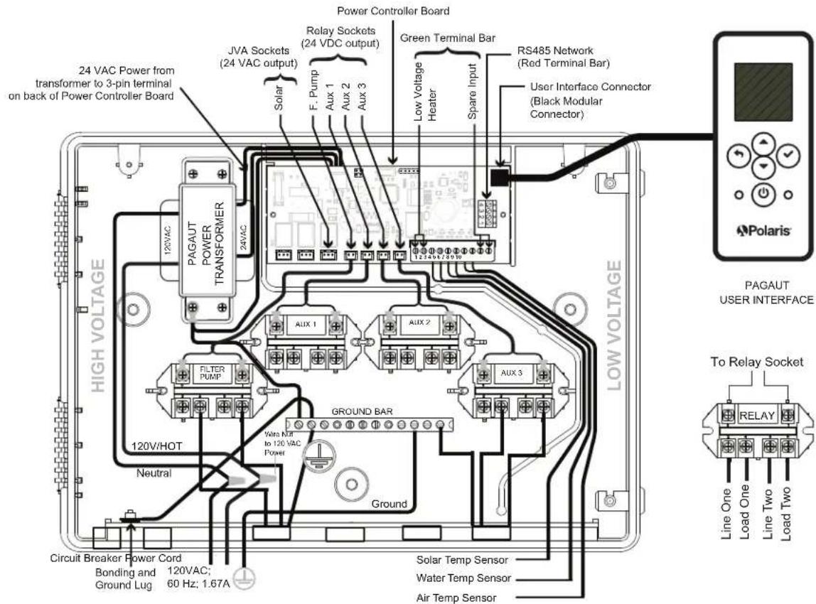
Section 4. High Voltage Plug In
4.1 Plug In Assignment
The following call-outs display the plug in assignments of the pool equipment.
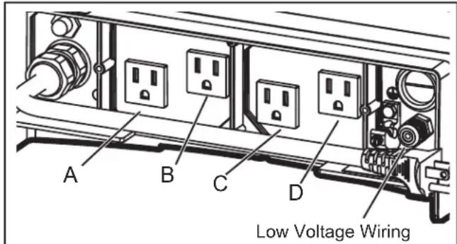
A - Filtration Pump: (120 VAC, 60Hz, 10A Max)
B (Aux 2) - Saltwater Chlorinator / Water Sanitizer: (120 VAC, 60Hz, 3A Max)
C (Aux 2) & D (Aux 3) - Low Voltage Light Transformer: (120 VAC, 60Hz, 1A Max)
Section 5. Low Voltage Wiring
All low voltage wiring should be run through the knockouts in the low voltage compartment (right side of controller enclosure).
IMPORTANT: Never run high voltage and low voltage in the same conduit.
5.1 Wire the Temperature Sensors
Wire the temperature sensors on the 10-pin green connector. The air temperature sensor is factory-installed on the 10-pin green connector (pins 7,8). The water temperature sensor and necessary installation hardware is included.
5.2 Install the Water Temperature Sensor
- Drill a hole (3/8") for mounting the water temperature sensor line in the pipe between the pump and the filter (before the heater).
- Install the O-ring on the sensor and insert the sensor into the hole. Wrap and tighten metal clamp around the pipe to secure sensor.
- Feed the sensor wire through the black low voltage wiring knockout.
- Strip 1/4" of insulation and separate the wires.
- Connect sensor wires to pins 5 and 6 of the 10-pin green connector.
5.3 Install a Solar Sensor (if applicable)
If there is a solar panel in the equipment configuration, wire the solar panel temperature sensor to the 10-pin green connector. The solar sensor should be installed adjacent to the solar panel so it will sense the same temperature as the solar panels. Do not install in the pipe.
- Feed the sensor wire through the black low voltage wiring knockout.
- Strip 1/4" of insulation and separate the wires.
- Connect sensor wires to pins 3 and 4.
5.4 Install Additional Low Voltage Equipment (i.e., Heater Connection)
If there is additional low voltage equipment installed, such as low voltage heating, wire to pins 1 and 2 on the 10-pin green connector.
5.5 Install iAquaLink ™ (if applicable)
NOTE: For complete instructions and safety information, refer to the iAquaLink Quick Start Guide (included in the iAquaLink packaging), or the full iAquaLink manual (found online at www.PolarisPool.com).
5.6 Mount the iAquaLink Device
Mount the iAquaLink at least 6 feet off the ground and at least 8 feet from motors, such as a blower.
5.7 Wire the iAquaLink Device
Wire the iAquaLink device on the red RS-485 connector.
- Feed wire through the black low voltage wiring knockout.
- Connect four (4) separate wires to each terminal.
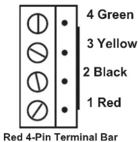
NOTE: Wire only two (2) devices (e.g, the iAquaLink™ and one additional device) to the RS-485 connector. If you have more than one additional device in your equipment configuration, use a multiplex board.
5.8 Install Jandy Valve ^® Actuators (JVAs) (if applicable)
You may wire up to a JVA on the PAC to control a water feature or solar panel, for example.
You may wire up to a JVA on the PAC to control a water feature or solar panel, for example.
NOTE: Read and follow complete installation instructions and safety information in the Jandy Valve Actuator owner's manual (included in the JVA packaging).
- Install JVA on equipment lines according to installation instructions in the owner's manual.
- Feed intake JVA wire through the black low voltage wiring knockout.
- Plug JVAs to Solar socket.
- If the solar sensor is installed the solar JVA will automatically assign to Solar Heat. If solar sensor is not installed the solar JVA may be assigned to one of the three (3) assemblies.
Section 6. User Interface
All system programming and installation setup is performed through the automation system user interface UI.
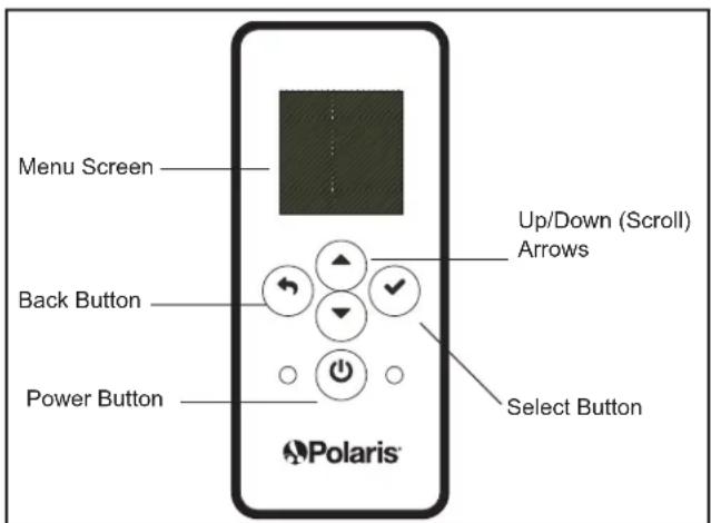
6.1 Navigation Buttons
Use the following buttons on the user interface to access and select all menus and commands:


Scroll up/down within current menu to highlight a specific menu command.


Select
Select current highlighted menu command.
Display the next menu or activate the selected function.
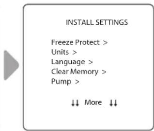
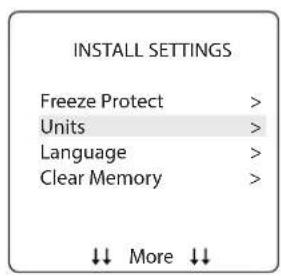
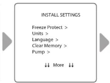
Section 7. Install Settings
Install Settings is a hidden menu, mostly used for setup and reference purposes.
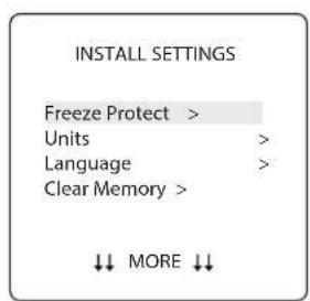
Settings available through this menu:
- Freeze Protect
Automatically turn specific equipment on to protect against freezing temperatures.
- Units
Change units of measurement displayed on the User Interface (temperature and time format).
- Language
Change language displayed on the User Interface.
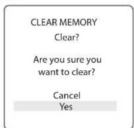
- Clear Memory
Clear all programmed data in the controller for all equipment.
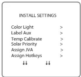
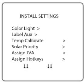
- Color Lights
Only available if specific lights are installed in your configuration.
- Label Aux
Assign custom labels to auxiliary equipment, such as an air blower, cleaner, solar pump, etc.
- Temp Calibrate
Adjust temperature displayed on the User Interface up or down by four (4) degrees.
- Solar Priority
Only available if solar heating is installed in your system.
- Assign JVA
Assign Jandy Valve® Actuators (JVAs) to specific AUX relays, as intake or return in Pool Only mode.
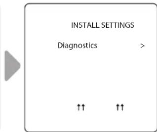
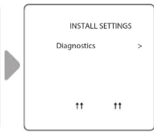
- Diagnostics
Display software revision information and alerts for troubleshooting purposes.
To access the Install Settings Menu:
- Press and hold Up/Down arrow keys at the same time for about 5 seconds.
7.1 Freeze Protect
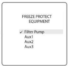
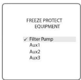
NOTE By factory default the filter pump circuit is freeze protected. During freeze protection, the filter pump cannot be turned off.
IMPORTANT
Freeze protection is intended to protect equipment and plumbing for short periods of freezing only. It does this by activating the filtration pump and circulating the water to prevent freeze inside equipment or plumbing. Freeze protection does not guarantee that equipment will not be damaged by extended periods of freezing temperatures or power outages. In these conditions, the pool and spa should be shut down completely (e.g. drained of water and closed for the winter) until warmer weather exists.

CAUTION
Activating the spa during freezing conditions will override freeze protection. This means that if you are using your spa when freezing conditions exist, freeze protection will not circulate water to non-spa related equipment that you may have freeze protected (e.g. pool cleaner, booster pump.) Under these circumstances, the potential for equipment damage may exist.
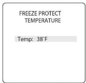
Set Temperature:
INSTALL SETTINGS > FREEZE PROTECT > SET TEMP
Set outside temperature at which freeze protect function is activated. Activation temperature can be adjusted between 34^ F and 42^ F. Default freeze protection activation temperature is 38^ F. The freeze protected equipment will turn off when the temperature increases 2^ F above the activation temperature.
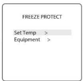

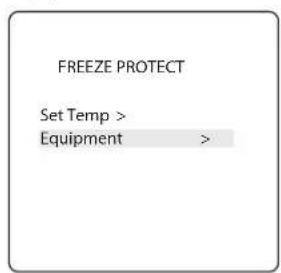
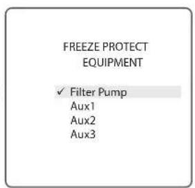
Select Equipment:
INSTALL SETTINGS > FREEZE PROTECT > EQUIPMENT
Assign freeze protection to a selected piece of equipment.
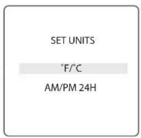
7.2 Units
INSTALL SETTINGS>UNITS
Change the temperature units (Fahrenheit - Celcius) and time format (12-hour AM/PM to 24-hour clock).
7.3 Languages
MAIN/STATUS>MENU>SYSTEM SETUP>LANGUAGE
Change the language displayed on the user interface. Languages available are:
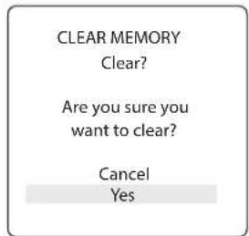
Clear all stored values (e.g., auxiliary labels, programs, remote settings, and thermostat settings) from the Polaris PAC memory. All settings will be reset to default factory settings. Time and date is not cleared.
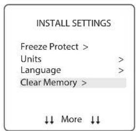
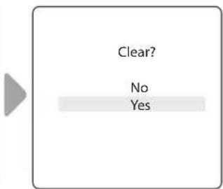
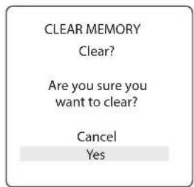
- The system asks you to verify you are sure you want to clear memory.
- There is a 15-second delay and *MEMORY CLEARED* message is displayed.
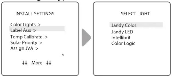
7.5 Color Lights
INSTALL SETTINGS > COLOR LIGHTS
NOTE You will only see this option if colored lights are installed in your system.
Select type of light installed (e.g., Jandy Colors™ or Jandy® LED Light) and assign the light to an available auxiliary relay.
Select Light Type:
flowchart
graph LR
    A["INSTALL SETTINGS"] --> B["SELECT LIGHT"]
    A --> C["Color Lights >"]
    A --> D["Label Aux >"]
    A --> E["Temp Calibrate >"]
    A --> F["Solar Priority >"]
    A --> G["Assign JVA >"]
    A --> H["More ↓↓"]
    A --> I["↓↓"]
    style A fill:#f9f,stroke:#333
    style B fill:#ccf,stroke:#333
    style C fill:#cfc,stroke:#333
    style D fill:#fcc,stroke:#333
    style E fill:#cff,stroke:#333
    style F fill:#ffc,stroke:#333
    style G fill:#cfc,stroke:#333
    style H fill:#fcc,stroke:#333
    style I fill:#cfc,stroke:#333
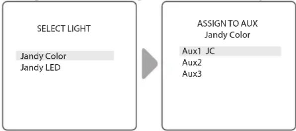
Assign Selected Light to an Auxiliary:
flowchart
graph LR
    A["SELECT LIGHT\nJandy Color\nJandy LED"] --> B["ASSIGN TO AUX\nJandy Color\nAux1 JC\nAux2\nAux3"]
- JC is displayed next to AUX if a Jandy Colors light has been assigned.
- JL is displayed next to AUX if a Jandy LED Light has been assigned.
- Press Select button with JC or JL highlighted to toggle control by the auxiliary on or off.
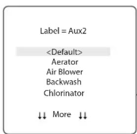
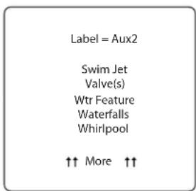
7.6 Label Auxiliary Functions
INSTALL SETTINGS>LABEL AUX
Assign labels to auxiliary equipment to display text in the user interface instead of AUX 1, 2, or 3.
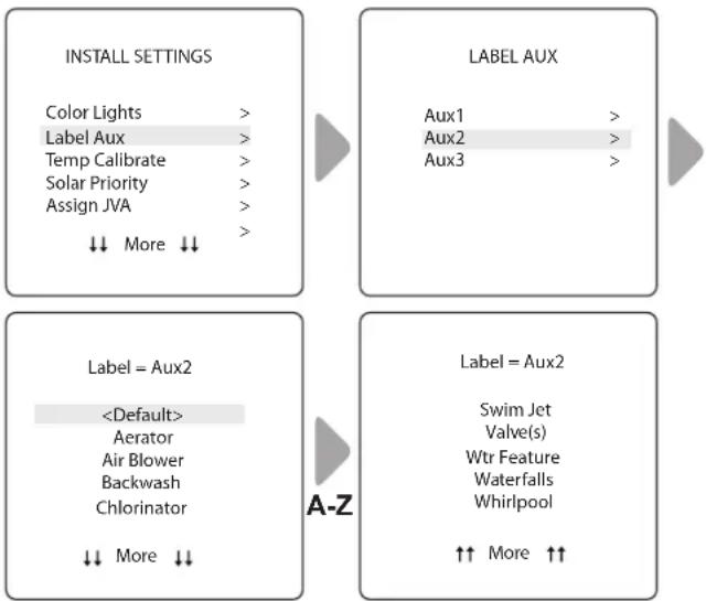
flowchart
graph TD
    A["INSTALL SETTINGS"] --> B["LABEL AUX"]
    B --> C["Label = Aux2"]
    C --> D["Label = Aux2"]
    style A fill:#f9f,stroke:#333
    style B fill:#ccf,stroke:#333
    style C fill:#cfc,stroke:#333
    style D fill:#fcc,stroke:#333
- Choose from labels listed A-Z on each screen.
7.7 Temp Calibrate
INSTALL SETTINGS>TEMP CALIBRATE
Adjust temperature displayed on the Polaris PAC up or down by 4 degrees.
NOTE If the temperature is off by more than four (4) degrees, contact your local service representative.
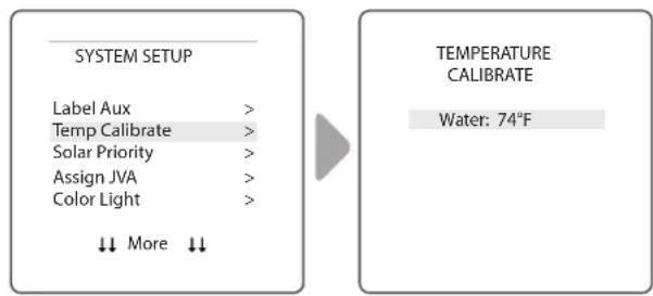
- Use Up/Down arrows to set new temperature value.
7.8 Solar Priority (if applicable)
INSTALL SETTINGS>SOLAR PRIORITY
NOTE: You will only see this option if solar heating is installed in your system.
Enable the system to use solar heat first, when available. If solar heat is no longer available, the system will automatically switch to the alternate heat source.
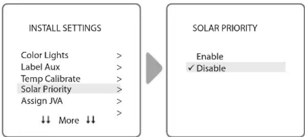
flowchart
graph LR
    A["INSTALL SETTINGS"] --> B["SOLAR PRIORITY"]
    A --> C["Color Lights >"]
    A --> D["Label Aux >"]
    A --> E["Temp Calibrate >"]
    A --> F["Solar Priority >"]
    A --> G["Assign JVA >"]
    A --> H["More ↓↓"]
    B --> I["Enable ✓ Disable"]
- When solar and heater are enabled the solar will heat the water until either the thermostat setting has been reached or solar heat is no longer available.
- If the solar panel is not hot enough, solar heat will shut off and the other heat source (usually gas heater) will take over to bring the water up to the thermostat setting.
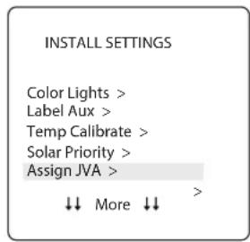
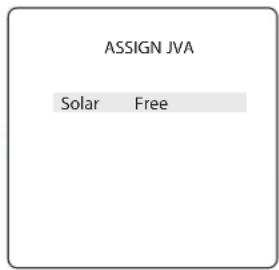
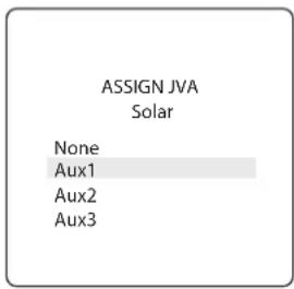
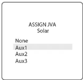
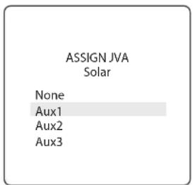
7.9 Assign JVA
INSTALL SETTINGS>ASSIGN JVA
NOTE: If the system is a pool/spa combination, without solar, only the solar JVA is assignable. If the system is a pool or spa only system, without solar, all three JVAs are assignable. The example shown is for a pool or spa only system without solar.
Allow Jandy Valve® Actuators (JVAs) to be assigned to any auxiliary on the Polaris PAC controller, so that when you select this auxiliary, the valve turns. Assigning JVAs lets the pool owner control certain features like diverting water to a waterfall or bank of spa jets. Multiple JVAs can be assigned to one auxiliary without extra hardware.
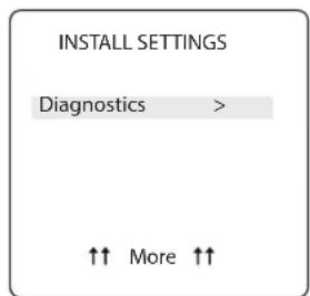
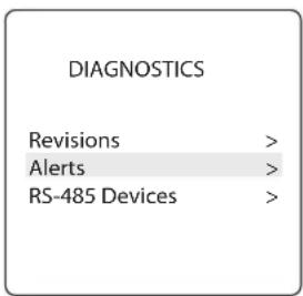
7.10 Diagnostics
INSTALL SETTINGS>DIAGNOSTICS
For troubleshooting purposes, view diagnostic information relating to current firmware revisions, system alerts or error messages, and status of devices connected to the RS-485 controller.
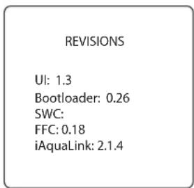
View Revision Number:
INSTALL SETTINGS>DIAGNOSTICS>REVISIONS
View your system firmware revision number for troubleshooting.
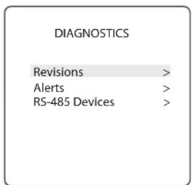
View Alert Messages
INSTALL SETTINGS>DIAGNOSTICS>ALERTS
View alerts or error messages. See Section 10. Glossaries for a complete list and explanation of all system messages.
![CURRENT ALERTS [BLANK UNTIL AN ALERT OCURS]](/content/2026/04/611139/images/73348358e564919a18e3b60506485b6aca527b19be09d91b3b95b840c2bc1013.jpg)
- Screen is blank if the controller has no errors to report.
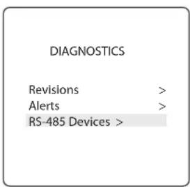
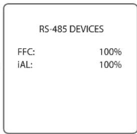
View RS-485 Device Status:
INSTALL SETTINGS>DIAGNOSTICS>RS-485 DEVICES
View status of devices connected to the RS-485 controller. Depending on your equipment configuration, any combination of the following equipment may be displayed:
• FFC - Polaris PAC Controller
- iAL - iAquaLink
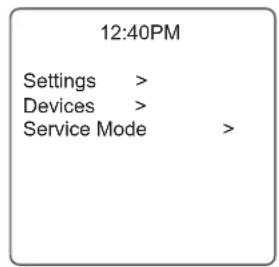
Section 8. Main Menu
From the Main menu, access commands to turn equipment on/off, program scheduled times to turn equipment on/off automatically, and view current operating status for specific equipment in your configuration.
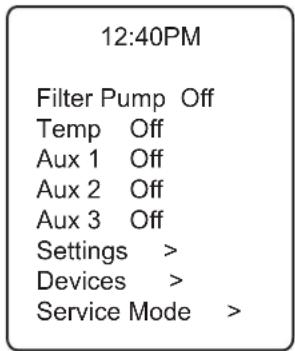
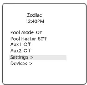
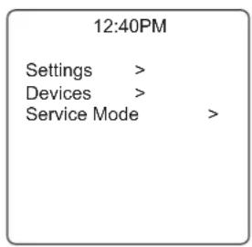
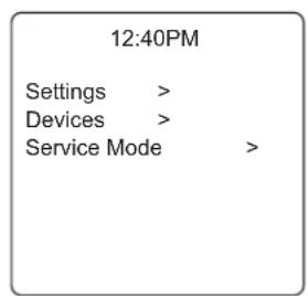
MAIN MENU
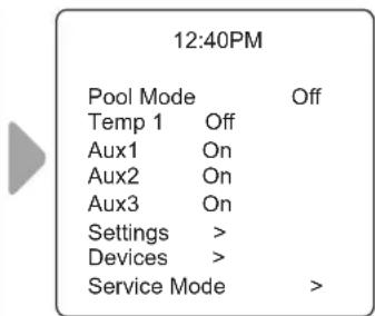
8.1 Equipment Status
If any of the equipment is currently enabled in your system, the screen alternately displays the Main menu and the Equipment Status screen.
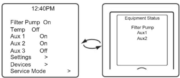
flowchart
graph LR
    A["12:40PM"] --> B["Filter Pump On Temp Off Aux 1 On Aux 2 On Aux 3 Off Settings > Devices > Service Mode >"]
    B --> C["Equipment Status"]
    C --> D["Filter Pump Aux1 Aux2"]
8.2 Filter Pump
MAIN > FILTER PUMP
Turn on Filter Pump whenever you want to filter the pool. Filter Pump enables the filter pump to circulate water through the filter and pool heater.
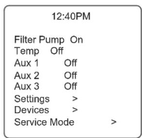
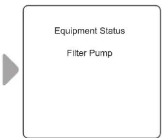
- When Filter Pump is activated, the Equipment Status menu is displayed indicating the Filter Pump is ON.
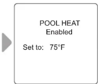
8.3 Pool Heater On/Off
MAIN > POOL HEATER
Enable the heater for the pool. Heater will turn on automatically as long as the filter pump is on and the water temperature is below the temperature set point.
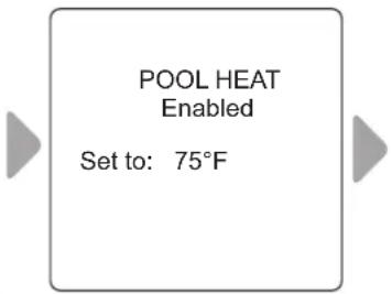
- Increase or decrease current pool temperature by pressing Select to highlight the setting. Press Up/Down arrows to increase or decrease temperature.
- To turn pool heater OFF, press Select when Pool Heater is highlighted in the Main menu.
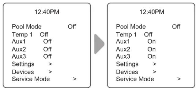
8.4 Turn Aux1, Aux2 or Aux3 On/Off
MAIN > AUX1, AUX2, AUX3
NOTE: If you have assigned labels to auxiliary equipment, the label will be displayed in the Main menu.
Turn ON or OFF auxiliary equipment, for example pool lights, salt chlorinator, or UV system.
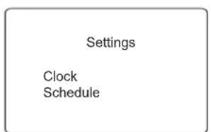
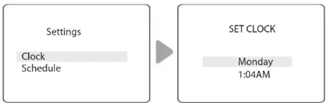
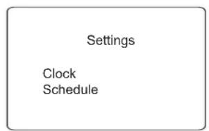
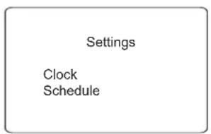
Set the System Clock:
$$ M A I N > S E T T I N G S > C L O C K $$
Set the current day of the week and time. This setting is the time clock basis for defining schedules for the filter pump and other equipment.
flowchart
graph LR
    A["Settings\nClock\nSchedule"] --> B["SET CLOCK\nMonday\n1:04AM"]
- Current programmed day flashes when selected. Scroll through days of the week to display desired day, then press Select.
- Current programmed time (hour) flashes when selected. Scroll through 24 hours to display desired time, then press Select.
- Current programmed time (minutes) flashes when selected. Scroll through 60 minutes to display desired time, then press Select.
Define Specific Equipment ON/OFF Schedules:
$$ M A I N > S E T T I N G S > S C H E D U L E S $$
Define automatic ON and OFF times for specific equipment in your installation. You may set different schedules for any single day, weekdays, weekends, or assign the same schedule for all days. Set a maximum of ten programs combined.
Define schedules for the following equipment as applicable:
- Filter Pump
- Pool Heater
• Solar Heater (if applicable) - Aux1, Aux2, and Aux3 (as applicable)
NOTE: You will only see equipment listed in the menu if it is installed as part of your system.
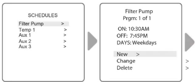
Example: Define Filter Pump Schedule
$$ \text { MAIN } > \text { SETTINGS } > \text { SCHEDULES } > \text { FILTER PUMP } $$
NOTE: Example shown is for defining the filter pump schedule. The procedure to define or change ON / OFF times for all equipment listed in Schedules Menu is identical to defining Filter Pump schedule.
- Choose CHANGE to change the current displayed schedule for selected equipment.
-
Choose DELETE to remove the current schedule from system programming. The system asks for verification: Delete? No Yes.
-
If there is no schedule currently set up for the selected equipment, the system displays the message: No Schedules Entered. Choose NEW to begin programming a schedule.
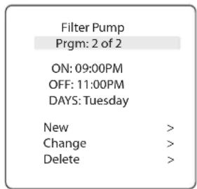
- If there is more than one schedule currently set up for the selected equipment, the system indicates total number of programs currently entered for this equipment (e.g., Program 2 of 2).
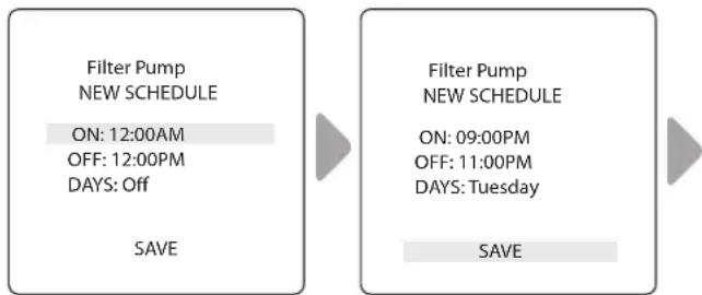
- Set ON time and OFF times:
– Current programmed time (hour) flashes when selected. Scroll through 24 hours to display desired time, then press Select.
- Current programmed time (minutes) flashes when selected. Scroll through 60 minutes to display desired time, then press Select.
- Set DAYS:
– Current programmed day flashes when selected. Scroll through days of the week to display desired day, ALL DAYS, WEEKENDS, or WEEKDAYS, then press Select.
- When you select SAVE to enter new program data, the system indicates total number of programs currently entered for this equipment (e.g., Program 2 of 2).
8.5 Turn Specific Equipment On/Off Manually
MAIN > DEVICES
Example: Define Filter Pump Schedule
flowchart
graph LR
    A["SCHEDULES"] --> B["Filter Pump"]
    A --> C["Filter Pump Prgm: 1 of 1"]
    B --> D["ON: 10:30AM"]
    B --> E["OFF: 7:45PM"]
    B --> F["DAYS: Weekdays"]
    B --> G["New >"]
    B --> H["Change"]
    B --> I["Delete"]
flowchart
graph LR
    A["Filter Pump NEW SCHEDULE<br>ON: 12:00AM<br>OFF: 12:00PM<br>DAYS: Off"] --> B["Save"]
    C["Filter Pump NEW SCHEDULE<br>ON: 09:00PM<br>OFF: 11:00PM<br>DAYS: Tuesday"] --> D["SAVE"]
- Choose NEW to keep the schedule displayed and program an additional schedule for selected equipment.
Turn selected equipment ON and OFF manually. The following equipment may be displayed depending on your pool's configuration:
- Filter Pump
- Temp1
- Solar Heat (*only displayed if a solar heater and solar sensor is part of your configuration)
- Aux1, Aux2, and Aux3 (* only if unlabeled auxiliaries; labeled equipment is displayed by name)
8.6 Turn All Equipment Off
MAIN > DEVICES > ALL OFF
Manually turn OFF all equipment that is currently turned on or enabled in your system.
| Air 78°F | |
| Filter Pump Off | |
| Temp 1 | > |
| Aux 1 | > |
| Aux 2 > | |
| Aux3 | > |
| Settings | > |
| Devices | > |
| Service Mode > | |

| Devices | |
| Filter Pump | > |
| Temp 1 | > |
| Aux1 | Off |
| Aux2 | Off |
| Aux3 | On |
| All Off | |
| ↑↑ | ↑↑ |
Section 9. Pool Only System Menu Flow Diagrams
9.1 Main Menu
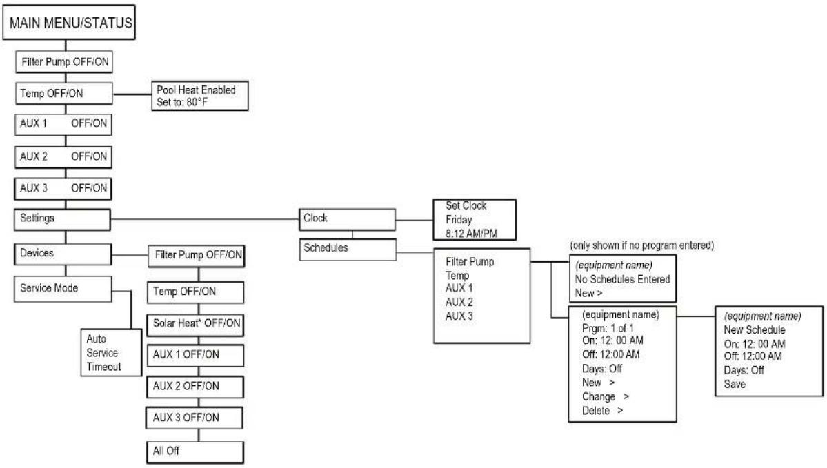
flowchart
graph TD
    A["MAIN MENU/STATUS"] --> B["Filter Pump OFF/ON"]
    B --> C["Temp OFF/ON"]
    C --> D["AUX 1 OFF/ON"]
    D --> E["AUX 2 OFF/ON"]
    E --> F["AUX 3 OFF/ON"]
    F --> G["Settings"]
    G --> H["Devices"]
    H --> I["Service Mode"]
    I --> J["Auto Service Timeout"]
    J --> K["Filter Pump OFF/ON"]
    K --> L["Temp OFF/ON"]
    L --> M["Solar Heat* OFF/ON"]
    M --> N["AUX 1 OFF/ON"]
    N --> O["AUX 2 OFF/ON"]
    O --> P["AUX 3 OFF/ON"]
    P --> Q["All Off"]

    C --> R["Pool Heat Enabled Set to: 80°F"]
    G --> S["Clock"]
    S --> T["Schedules"]
    T --> U["Set Clock Friday 8:12 AM/PM"]
    U --> V["Filter Pump Temp AUX 1 AUX 2 AUX 3"]
    V --> W["(only shown if no program entered)"]
    V --> X["(equipment name) No Schedules Entered New >"]
    V --> Y["(equipment name) Prgm: 1 of 1 On: 12:00 AM Off: 12:00 AM Days: Off New > Change > Delete >"]
    V --> Z["(equipment name) New Schedule On: 12:00 AM Off: 12:00 AM Days: Off Save"]
9.2 Install Settings Menu
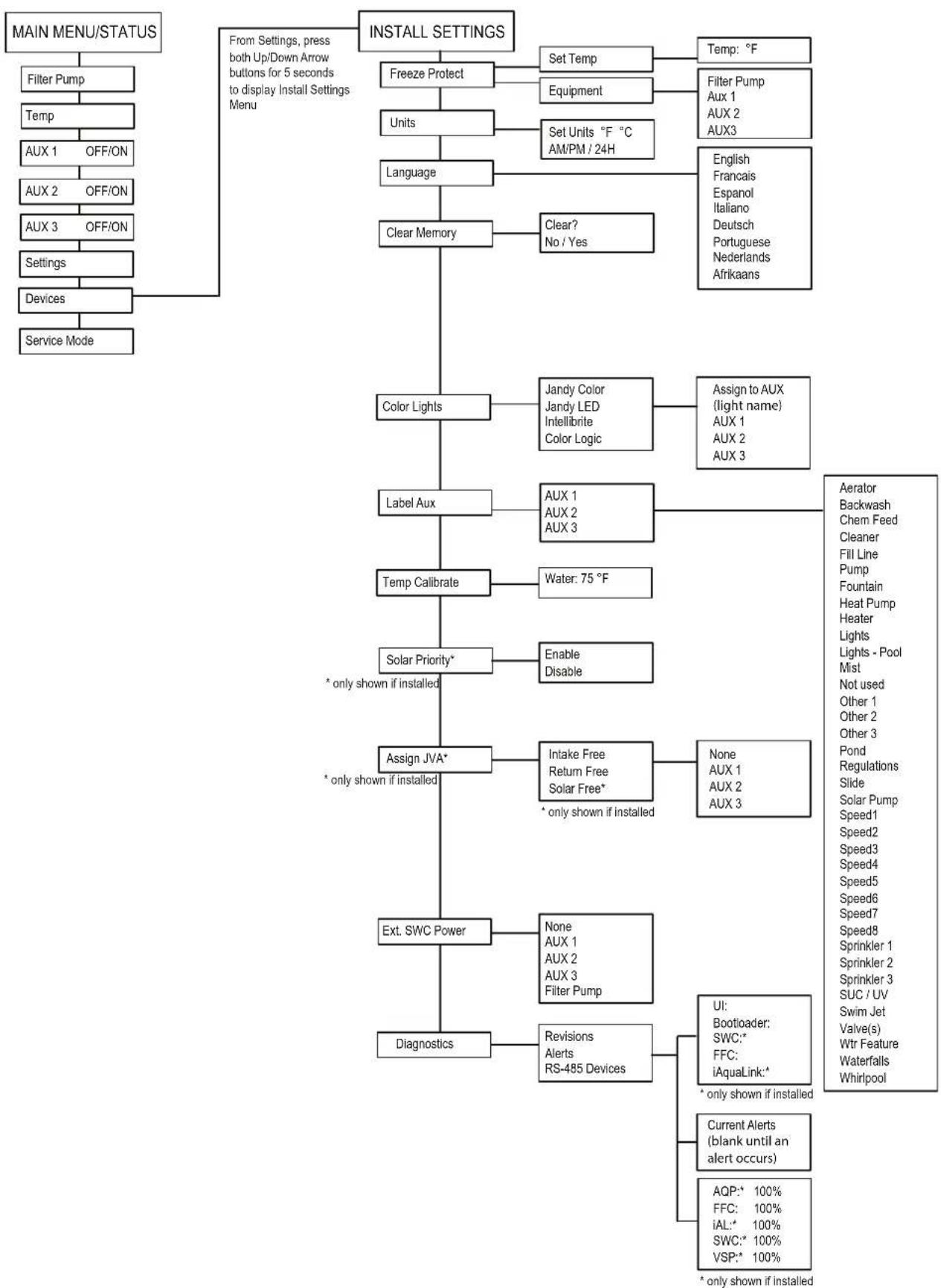
flowchart
graph TD
    A["MAIN MENU/STATUS"] --> B["Filter Pump"]
    B --> C["Temp"]
    C --> D["AUX 1 OFF/ON"]
    D --> E["AUX 2 OFF/ON"]
    E --> F["AUX 3 OFF/ON"]
    F --> G["Settings"]
    G --> H["Devices"]
    H --> I["Service Mode"]

    J["INSTALL SETTINGS"] --> K["Freeze Protect"]
    K --> L["Units"]
    L --> M["Language"]
    M --> N["Clear Memory"]
    N --> O["Color Lights"]
    O --> P["Label Aux"]
    P --> Q["Temp Calibrate"]
    Q --> R["Solar Priority*"]
    R --> S["Assign JVA*"]
    S --> T["Ext. SWC Power"]
    T --> U["Diagnostics"]

    V["From Settings, press both Up/Down Arrow buttons for 5 seconds to display Install Settings Menu"] --> W["Set Temp"]
    W --> X["Equipment"]
    X --> Y["Set Units °F °C AM/PM / 24H"]
    Y --> Z["Clear? No / Yes"]

    AA["Temp: °F"] --> AB["Filter Pump Aux 1 AUX 2 AUX3"]
    AB --> AC["English Francais Espanol Italiano Deutsch Portuguese Nederlands Afrikaans"]

    AD["Assign to AUX (light name) AUX 1 AUX 2 AUX 3"] --> AE["Aerator Backwash Chem Feed Cleaner Fill Line Pump Fountain Heat Pump Heater Lights Lights - Pool Mist Not used Other 1 Other 2 Other 3 Pond Regulations Slide Solar Pump Speed1 Speed2 Speed3 Speed4 Speed5 Speed6 Speed7 Speed8 Sprinkler 1 Sprinkler 2 Sprinkler 3 SUC / UV Swim Jet Valve(s) Wtr Feature Waterfalls Whirlpool"]

    AF["* only shown if installed"] --> AG["* only shown if installed"]

    AH["Enable Disable"] --> AI["Assign JVA*"]
    AI --> AJ["Intake Free Return Free Solar Free*"]
    AJ --> AK["* only shown if installed"]

    AL["None AUX 1 AUX 2 AUX 3"] --> AM["* only shown if installed"]

    AN["UI: Bootloader: SWC:* FFC: iAquaLink:* * only shown if installed"] --> AO["Current Alerts (blank until an alert occurs)"]
    AO --> AP["AQP:* 100% FFC: 100% iAL:* 100% SWC:* 100% VSP:* 100% * only shown if installed"]
Section 10. Glossaries
10.1 Glossary of Safety Delays and Lockouts
Heater Cool Down Delay
When the system is heating and the Filter Pump is turned off, the Filter Pump will remain on for five (5) minutes, and will continue to circulate the water. This delay allows water to cool the heater down by circulating water through it, preventing equipment damage. The five (5) minute delay starts counting down when the heater goes off. If the heater has been off for five (5) minutes or more, prior to turning off the Filter Pump, there will not be a delay.
Heater Start-up
The heater will only come on if the water is circulating (for example, the filter pump is on and has been circulating for 15 seconds) and the actual water temperature is below the temperature you set with Temp Set in the Menu. If these conditions are not met, the heater will be enabled (ready to go), but will not fire.
Heater "Short Cycling" Prevention
When the heater is activated and the desired temperature is reached, heater will turn off and remain off for three (3) minutes, even if the temperature falls below the desired temperature. This feature prevents heater short cycling (in other words, the heater turning off and on in rapid succession).
Cleaner Lockout
The pool cleaner will only activate if the Filter Pump is on and water is circulating. The pool cleaner requires that water is circulating to the pool in order for it to operate.
Enabled
When activated allows the function to work.
Disabled
When activated does not allow the function to work.
10.2 Glossary of Alert Messages
FREEZE PROTECT
This message indicates that freezing conditions have been detected by the freeze protection sensor, and that equipment assigned to freeze protection are active (for example, the filter pump). See Freeze Protection Menu for more information.
NOTE: The filter pump is always protected; auxiliary circuits can be assigned to freeze protection. If a freeze protected Auxiliary is turned off during freeze protection, a message will be displayed indicating that item is off but will turn on in X amount of minutes. The minutes will vary depending on how long freeze mode has been active from one (1) to 15 minutes.
SENSOR OPEN
This error message indicates that the sensor is not installed properly or is malfunctioning. Call your pool service person to resolve this problem.
NOTE: If the message reads Water TEMP Open, the heater will not fire. If message Air TEMP OPEN is displayed, freeze protection will not operate correctly.
This message is displayed when you attempt to turn off the filter pump while a spa spillover is on. Since the filter pump is necessary for spillover operation, the pump will remain on until the spillover is turned off.
This message indicates that the filter pump is circulating water to cool down the heater. The filter pump will continue to run for five minutes to protect the heater from damage, whenever the heater has fired and has been off for less than five (5) minutes.
SERVICE MODE
Service mode is used by the pool service person to aid them in servicing the pool.
SENSOR SHORT
This error message indicates that the sensor is not installed properly or is malfunctioning. Call your pool service person to resolve this problem.
NOTE: If the message reads WATER TEMP SHORT, the heater will not fire. If the message AIR TEMP SHORT is displayed, freeze protection will not operate correctly.
TIME-OUT MODE
Time Out mode is used by the pool service person to aid them in servicing the pool. The automation system user interface will not be functional for three (3) hours, or until the switch at the Controller is turned back to AUTO mode. The time remaining for TIME OUT mode is displayed on the user interface screen
Section 11. Wiring Diagram
NOTES
Zodiac Pool Systems LLC
2882 Whiptail Loop # 100
Carlsbad, CA 92010, USA
1.800.822.7933
PolarisPool.com
Zodiac Pool Systems Canada, Inc.
2-3365 Mainway, Burlington,
ON L7M 1A6, Canada
1.800.822.7933
PolarisPool.ca
©2022 Zodiac Pool Systems LLC. All rights reserved. Polaris® and the Polaris 3-wheeled cleaner design are registered trademarks of Zodiac Pool Systems LLC. All other trademarks referenced herein are the property of their respective owners.
H0770000_REVB

ETL LISTED CONFORMS TO UL STD 1563 Certified to CAN/CSA C22.2 N° 218.1
natural_image
Line drawing of a portable electronic device with control panel, power cord, and plug (no text or symbols)1 500 watts incandescent
Basse tension - Classe 2,
1 A à 24 V. c.a.
7.2 Unités
PARAMÈTRES D'INSTALLATION>UNITÉS
flowchart
graph LR
    A["SELECT LIGHT\nJandy Color\nJandy LED"] --> B["ASSIGN TO AUX\nJandy Color\nAux1 JC\nAux2\nAux3"]
7.10 Diagnostics
PARAMÈTRES D'INSTALLATION > DIAGNOSTICS
Section 8. Menu principal
flowchart
graph LR
    A["12:40PM"] --> B["Filter Pump On"]
    B --> C["Temp Off"]
    C --> D["Aux 1 On"]
    D --> E["Aux 2 On"]
    E --> F["Aux 3 Off"]
    F --> G["Settings >"]
    G --> H["Devices >"]
    H --> I["Service Mode >"]
    I --> J["Equipment Status"]
    J --> K["Filter Pump<br>Aux1<br>Aux2"]
    K --> L["~"]
    L --> M["Feedback Loop"]
flowchart
graph LR
    A["Settings\nClock\nSchedule"] --> B["SET CLOCK\nMonday\n1:04AM"]
flowchart
graph TD
    A["SCHEDULES"] --> B["Filter Pump Prgm: 1 of 1"]
    B --> C["Filter Pump NEW SCHEDULE"]
    C --> D["Filter Pump NEW SCHEDULE"]
    D --> E["Final Output"]

    subgraph SCHEDULES
        F["Filter Pump > Temp 1 > Aux 1 Aux 2 Aux 3"]
    end

    subgraph Filter Pump
        G["ON: 10:30AM OFF: 7:45PM DAYS: Weekdays"]
        H["New > Change Delete"]
    end

    subgraph NEW SCHEDULE
        I["ON: 12:00AM OFF: 12:00PM DAYS: Off"]
        J["SAVE"]
    end

    subgraph Final Output
        K["ON: 09:00PM OFF: 11:00PM DAYS: Tuesday"]
        L["SAVE"]
    end
Filter Pump
Prgm: 2 of 2
ON: 09:00PM
OFF: 11:00PM
DAYS: Tuesday
New >
Change
Delete
Zodiac Pool Systems LLC
2882 Whiptail Loop # 100
Carlsbad, CA 92010, USA
1.800.822.7933
PolarisPool.com
Zodiac Pool Systems Canada, Inc.
2-3365 Mainway, Burlington,
ON L7M 1A6, Canada
1.800.822.7933
PolarisPool.ca
natural_image
Line drawing of a portable electronic device with control panel, power plug, and cable (no text or symbols)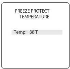
Seleccionar equipo:
7.2 Unidades

7.10 Diagnóstico
flowchart
graph LR
    A["12:40PM"] --> B["Filter Pump On"]
    B --> C["Temp Off"]
    C --> D["Aux 1 On"]
    D --> E["Aux 2 On"]
    E --> F["Aux 3 Off"]
    F --> G["Settings >"]
    G --> H["Devices >"]
    H --> I["Service Mode >"]
    I --> J["Equipment Status"]
    J --> K["Filter Pump Aux1 Aux2"]
8.2 Bomba del filtro
MAIN (PRINCIPAL) > FILTER PUMP (BOMBA DEL FILTRO)
flowchart
graph LR
    A["12:40PM"] --> B["Settings > Devices > Service Mode >"]
    C["POOL HEAT Enabled\nSet to: 75°F"] --> A

flowchart
graph LR
    A["Settings\nClock\nSchedule"] --> B["SET CLOCK\nMonday\n1:04AM"]
Zodiac Pool Systems LLC
2882 Whiptail Loop # 100
Zodiac Pool Systems Canada, Inc.
2-3365 Mainway, Burlington,
ON L7M 1A6, Canadá
1.800.822.7933
PolarisPool.ca
- Above-Ground
- Pool Automation Control
- WARNING
- Table of Contents
- Section 1. Important Safety Instructions....3
- Section 2. System Overview....5
- Section 3. Install Controller Box ....5
- Section 4. High Voltage Plug In....6
- Section 5. Low Voltage Wiring....6
- Section 6. User Interface....7
- Section 7. Install Settings....8
- Section 8. Main Menu....12
- Section 9. Pool Only System Menu Flow Diagrams....15
- Section 10. Glossaries ....17
- Section 11. Wiring Diagram....18
- FCC Regulatory Compliance Statement
- Section 1. Important Safety Instructions
- READ AND FOLLOW ALL INSTRUCTIONS
- DANGER
- CAUTION
- Section 2. System Overview
- Package Contents
- Electrical Specifications
- Materials and Tools
- Installation Materials Furnished
- Tools Needed for Installation
- Section 3. Install Controller Box
- Mount the Controller Enclosure
- Bonding the Power Center
- Section 4. High Voltage Plug In
- Plug In Assignment
- Section 5. Low Voltage Wiring
- Wire the Temperature Sensors
- Install the Water Temperature Sensor
- Install a Solar Sensor (if applicable)
- Install Additional Low Voltage Equipment (i.e., Heater Connection)
- Install iAquaLink ™ (if applicable)
- Mount the iAquaLink Device
- Wire the iAquaLink Device
- Install Jandy Valve ® Actuators (JVAs) (if applicable)
- Section 6. User Interface
- Navigation Buttons
- Select
- Section 7. Install Settings
- To access the Install Settings Menu:
- Freeze Protect
- IMPORTANT
- Set Temperature:
- Select Equipment:
- Units
- Languages
- Color Lights
- Label Auxiliary Functions
- INSTALL SETTINGS>LABEL AUX
- Temp Calibrate
- INSTALL SETTINGS>TEMP CALIBRATE
- Solar Priority (if applicable)
- INSTALL SETTINGS>SOLAR PRIORITY
- Assign JVA
- INSTALL SETTINGS>ASSIGN JVA
- Diagnostics
- INSTALL SETTINGS>DIAGNOSTICS
- View Revision Number:
- INSTALL SETTINGS>DIAGNOSTICS>REVISIONS
- View Alert Messages
- INSTALL SETTINGS>DIAGNOSTICS>ALERTS
- View RS-485 Device Status:
- INSTALL SETTINGS>DIAGNOSTICS>RS-485 DEVICES
- Section 8. Main Menu
- Equipment Status
- Filter Pump
- Pool Heater On/Off
- Turn Aux1, Aux2 or Aux3 On/Off
- Set the System Clock:
- Define Specific Equipment ON/OFF Schedules:
- Example: Define Filter Pump Schedule
- Turn Specific Equipment On/Off Manually
- Turn All Equipment Off
- Section 9. Pool Only System Menu Flow Diagrams
- Section 10. Glossaries
- Glossary of Safety Delays and Lockouts
- Heater Cool Down Delay
- Heater Start-up
- Heater "Short Cycling" Prevention
- Cleaner Lockout
- Enabled
- Disabled
- Glossary of Alert Messages
- FREEZE PROTECT
- SENSOR OPEN
- SERVICE MODE
- SENSOR SHORT
- TIME-OUT MODE
- NOTES
- Unités
- PARAMÈTRES D'INSTALLATION>UNITÉS
- PARAMÈTRES D'INSTALLATION > DIAGNOSTICS
- Section 8. Menu principal
- Seleccionar equipo:
- Unidades
- Diagnóstico
- Bomba del filtro
Brand : POLARIS
Model : PAC
Category : Controller