
3335 - Multimeter PeakTech - Free user manual and instructions
Find the device manual for free 3335 PeakTech in PDF.
| Product type | Digital multimeter |
| Brand | PeakTech |
| Model | 3335 |
| Display | LCD 38 mm, 3 1/2 digits, max 1999, with backlight |
| Dimensions | 92 (W) x 195 (H) x 38 (D) mm |
| Weight | 380 g |
| Power supply | 9 V battery |
| Auto power off | After 15 minutes of inactivity |
| Safety | CAT III 600 V, double insulation (class II), overload protection |
| Maximum input voltage | 600 V DC/AC |
| DC voltage measurement | 200 mV to 600 V, accuracy ±0.5% + 2 digits to ±0.8% + 2 digits |
| AC voltage measurement | 2 V to 600 V, accuracy ±1.0% + 3 digits to ±1.2% + 5 digits, frequency 50-100 Hz |
| DC current measurement | 200 µA to 10 A, accuracy ±1.0% + 3 digits to ±2.5% + 10 digits |
| AC current measurement | 2 mA to 10 A, accuracy ±1.2% + 3 digits to ±3.0% + 10 digits, frequency 50-100 Hz |
| Resistance measurement | 200 Ω to 20 MΩ, accuracy ±1.0% + 2 digits to ±2.0% + 5 digits |
| Capacitance measurement | 2 nF to 200 µF, accuracy ±4% + 3 digits to ±10% + 5 digits (for <100 µF) |
| Frequency measurement | 20 kHz, accuracy ±1.5% + 5 digits, sensitivity 0.2 V RMS to 10 V RMS |
| Temperature measurement | -20°C to +760°C (-4°F to +1400°F) with type K probe, accuracy ±3% + 3 digits |
| Special functions | Data Hold, diode test, audible continuity test, backlight, °C/°F selection |
| Fuses | F1: 200 mA/600 V (5x20 mm), F2: 10 A/250 V (6.3x32 mm) |
| Included accessories | Test leads, 9 V battery, temperature adapter, temperature probe |
Frequently Asked Questions - 3335 PeakTech
User questions about 3335 PeakTech
0 question about this device. Answer the ones you know or ask your own.
Ask a new question about this device
Download the instructions for your Multimeter in PDF format for free! Find your manual 3335 - PeakTech and take your electronic device back in hand. On this page are published all the documents necessary for the use of your device. 3335 by PeakTech.
USER MANUAL 3335 PeakTech
600 V DC/AC eff in allen anderen
Bereichen
natural_image
Simple line drawing of a trash bin with diagonal lines crossing the rim (no text or symbols)This product complies with the requirements of the following European Community directives: 2014/30/EU (Electromagnetic Compatibility) and 2014/35/EU (Low Voltage) as amended by 2014/32/EU (CE-Marking). Overvoltage CAT III 600V, Pollution degree 2.
CAT I: For signal level, telecommunication, electronic with small transient over voltage
CAT II: For local level, appliances, main wall outlets, portable equipment
CAT III: Supplied from a cable under earth; fixed installed switches, automatic cut-off or main plugs
CAT IV: Units and installations, which are supplied overhead lines, which are stand in a risk of persuade of a lightning, i.e. main-switches on current input, overvoltage-diverter, current use counter.
To ensure safe operation of the equipment and eliminate the danger of serious injury due to short-circuits (arcing), the following safety precautions must be observed.
Damages resulting from failure to observe these safety precautions are exempt from any legal claims whatever.
* Do not exceed the maximum permissible input ratings (danger of serious injury and/or destruction of the equipment).
* The meter is designed to withstand the stated max voltages. If it is not possible to exclude without that impulses, transients, disturbance or for other reasons, these voltages are exceeded a suitable prescale (10:1) must be used.
* Do not operate the meter before the cabinet has been closed and screwed safely as terminal can carry voltage.
* Replace a defective fuse only with a fuse of the original rating. Never short-circuit fuse or fuse holding.
* Disconnect test leads or probe from the measuring circuit before switching modes or functions.
* Do not conduct voltage measurements with the test leads connected to the mA/A- and COM-terminal of the equipment.
* The 10A-range is protected. To avoid damage or injury, use the meter only in circuits limited by fuse or circuit breaker to 10A or 2000VA.
* To avoid electric shock, disconnect power to the unit under test and discharge all capacitors before taking any resistance measurements.
* Do not conduct current measurements with the leads connected to the V/Ω-terminals of the equipment.
* Check test leads and probes for faulty insulation or bare wires before connection to the equipment.
* To avoid electric shock, do not operate this product in wet or damp conditions. Conduct measuring works only in dry clothing and rubber shoes, i. e. on isolating mats.
* Never touch the tips of the test leads or probe.
* Comply with the warning labels and other info on the equipment.
* Do not turn the rotary function switch during voltage or current measurement, otherwise the meter could be damaged.
* Do not input values over the maximum range of each measurement to avoid damages of the meter.
* Always start with the highest measuring range when measuring unknown values.
* Use caution when working with voltages above 35V DC or 25V AC. These Voltages pose shock hazard.
* Do not operate the equipment near strong magnetic fields (motors, transformers etc.).
* Do not subject the equipment to direct sunlight or extreme temperatures, humidity or dampness.
* Do not subject the equipment to shocks or strong vibrations.
* Keep hot soldering irons or guns away from the equipment.
* Allow the equipment to stabilize at room temperature before taking up measurement (important for exact measurements).
* Replace the battery as soon as the battery indicator “BAT” appears. With a low battery, the meter might produce false reading that can lead to electric shock and personal injury.
* Fetch out the battery when the meter will not be used for long period.
* Periodically wipe the cabinet with a damp cloth and mid detergent. Do not use abrasives or solvents.
* The meter is suitable for indoor use only
* Do not store the meter in a place of explosive, inflammable substances.
* Opening the equipment and service – and repair work must only be performed by qualified service personnel
* Do not modify the equipment in any way
* - Measuring instruments don't belong to children hands -
Cleaning the cabinet
Clean only with a damp, soft cloth and a commercially available mild household cleanser. Ensure that no water gets inside the equipment to prevent possible shorts and damage to the equipment.
1.1. Safety Symbols
The following symbols are imprinted on the front panel of the meter to remind you of measurement limitations and safety.
| 10 A | The maximum current that you can measure at this terminal is 10 A DC/AC. This terminal is fuse protected by F 10A/600 V fuse. When using this range with high current, keep the duty cycle to 30 sec. on load and 15 minutes off load. |
| mA | The maximum current that you can measure with this terminal is 200 mA that is fuse protected by 200 mA/600 V fuse. |
 | Refer to the complete operating instructions. |
 | To avoid electrical shock or instrument damage, do not connect the common Input COM Terminal to any source of 600 V DC/AC with respect to earth ground. |
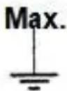
 | The maximum voltage this meter can measure is 600 V DC/AC |
| WARNING | This WARNING symbol indicates potentially hazardous situation, which if not avoided, could result in death or serious injury. |
 | Be exceptionally careful when measuring high voltages. Do not touch the terminals or test leads ends |
 | Indicates protection class II(Double Insulation) |
| CAT III | Overvoltage category III |
1.2. Input Limits
| Function | Terminal | Input limits |
| V DC | V/Ω/CAP/Hz/°C/°F+COM | 600 V DC/ACrms |
| V AC | 600 V DC/ACrms | |
| Ω | 250 V DC/ACrms | |
| mA DC/AC | mA + COM | 0,2 A / 600 V DC/AC |
| 10 A DC/AC | 10 A + COM | 10 A / 600 V DC/AC |
| →●))) | V/Ω/CAP/Hz/°C/°F+COM | 250 V DC/ACrms |
| Frequency | 250 V DC/ACrms | |
| Temperature | 250 V DC/ACrms | |
| Capacitance | 250 V DC/ACrms |
2. Introduction
The multimeter is heavy-duty and rugged hand-held multimeter that will give you confidence and peace of mind in your every measuring job. Please read these operating instructions very carefully before commencing your measurements.
* Data Hold Function - freezes the display so you can keep the measured value there even after you disconnect the probes.
* Auto polarity operation
* Overload and Transient protection
* Backlight
* Low Battery indicator appears when you need to replace the batteries.
* Beeper sounds tones for overload warning, continuity function and range selection.
* Auto power off
2.1. General Characteristics
| Display | 3 1/2 digit 38 mm LCD display, max. indication 1999, with automatic polarity indication |
| Overrange indication | "OL" |
| Low battery indication | Battery symbol „BAT“ appears, if battery is low |
| Reading time | 2 reading per second, nominal |
| Auto power off | after 15 minutes |
| Betriebstemperaturbereich | 0...50°C (32 ... 122°F) |
| Lagertemperaturbereich | -20...+60°C (-4 ... +140°F) |
| Temperaturbereich für angegebene Genauigkeit | 18...28°C; < 70% RH |
| Spannungsversorgung | 9 V battery (Neda 1604 or equivalent) |
| Abmessungen (B x H x T) | 92 x 195 x 38 mm |
| Gewicht | 380 g |
| Accessories | test leads, operating manual, battery, temperature adaptor, thermocouple |
3. Functions and Ranges
3.1. DC Voltage
| Range | Resolution | Accuracy |
| 200 mV | 100 μV | +/-0,5% rdg. + 2 dgt. |
| 2 V | 1 mV | |
| 20 V | 10 mV | |
| 200 V | 100 mV | |
| 600 V | 1 V | +/-0,8% rdg. + 2 dgt. |
Input impedance: 10 MΩ
Overload protection: 250 V DC/AC
rms
(15 Sec. in 200 mV range)
600 V DC/AC
rms in all other ranges
3.2. AC Voltage
| Range | Resolution | Accuracy |
| 2 V | 1 mV | +/- 1,0% rdg. + 3 dgt. |
| 20 V | 10 mV | |
| 200 V | 100 mV | |
| 600 V | 1 V | +/- 1,2% rdg. + 5 dgt. |
Input impedance: 10 MΩ
Frequency range: 50 ... 100 Hz
Overload protection: 600 V DC/AC
rms in all ranges
3.3. DC Current
| Range | Resolution | Accuracy |
| 2 mA | 1 μA | ±1,0% rdg. + 3 dgt. |
| 20 mA | 10 μA | ±1,5% rdg. + 3 dgt. |
| 200 mA | 100 μA | |
| 10 A | 10 mA | ±2,5% rdg.+ 10 dgt. |
Overload protection:
0,2 A / 600 V fuse in mA-Input (Fast-blow fuse)
10 A / 600 V fuse in 10 A-Input (Fast-blow fuse)
10 A for max. 30 sec.
3.4. AC Current
| Range | Resolution | Accuracy |
| 2 mA | 1 μA | +/- 1,2% rdg. + 3 dgt. |
| 200 mA | 100 μA | +/- 2,0% rdg. + 3 dgt. |
| 10 A | 10 mA | +/- 3,0% rdg. + 10 dgt. |
Frequency - range: 50 ... 100 Hz
Overload protection
0,2 A / 600 V fuse in mA-Input (Fast-blow fuse)
10 A / 600 V fuse in 10 A-Input (Fast-blow fuse)
10 A for max. 30 sec.
3.5. Resistance
| Range | Resolution | Accuracy |
| 200 Ω | 0,1 Ω | +/- 1,0% rdg. + 4 dgt. |
| 2 kΩ | 1 Ω | +/- 1,0% rdg. + 2 dgt. |
| 20 kΩ | 10 Ω | +/- 1,2% rdg. + 2 dgt. |
| 200 kΩ | 100 Ω | |
| 2 MΩ | 1 kΩ | |
| 20 MΩ | 10 kΩ | +/- 2,0% rdg. + 5 dgt. |
Overload protection:
250 V DC/ACrms
3.6. Frequency
| Range | Resolution | Accuracy |
| 20 kHz | 10 mHz | +/- 1,5% rdg. + 5 dgt. |
Input voltage: 250 V DC/AC
Sensitivity: 0,2 V
rms
rms ... 10 Vrms
3.7. Capacitance
| Range | Resolution | Accuracy |
| 2 nF | 1 pF | ± 4% rdg.+ 10 dgt. |
| 20 nF | 10 pF | ± 4% rdg.+ 3 dgt. |
| 200 nF | 0,1 nF | |
| 2 μF | 1 nF | |
| 200 μF | 0,1 μF | <100μF: ± 10% rdg. + 5 dgt.>100μF: Not specified |
Overload protection: 250 V DC/AC
rms
3.8. Temperature
| Range | Resolution | Accuracy |
| -20 ...+ 760°C | 1°C | ± 3% rdg.+ 3 dgt. |
| -4 ... + 1400°F | 1°F |
Sensor: Type-K Thermocouple
3.9. Diode
| Range | Resolution | Accuracy | Test-current | Open circuit voltage |
| 2 V | 1 mV | ±1,5% rdg. +3 dgt. | 1,0 mA | 2,8 V DC typical |
3.10. Continuity check
Audible continuity threshold: Less than 50 Ω
Test current: < 0,3 mA
Overload protection: 250 V DC or AC _rms
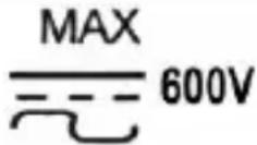
- Front Panel Description
text_image
HOLD 1333 20 1 9 10 PeakTech® 3335 DMM Ω 200 2K 20K 200K 2M 20M F 200u 2u 200m 20m 2n 2m 20m A— 200m 10 200m 2m TEMP 2 20K Hz 200m V~ 20 200 600 600 200 V~ 4 5 AUTO POWER OFF A~ 10A mA V-Ω CAP COM MAX 10A FUSED MAX 200mA FUSED CAT BI 600V MAX 600V FOR 30 SEC. MAX EVERY 10 MIN. 8 7Fig. 1
(1) 3 12 digit LCD-display with backlight
(2) Rotary selector
(3) COM input-jack
(4) V/Ω/CAP/Hz/Temp.-input jack
(5) mA input-jack
(6) 10 A input-jack
(7) DATA-HOLD
(8) °C/°F-button
(9) Backlight-button
(10) ON/OFF-button
4.1. Description
(1) Digital Display Digital readings are displayed on a 1999 count display with automatic polarity indication and decimal point placement.
(2) Function selector To select the measuring range
(3) COM Common Terminal Return terminal for all measurements.
(4) V/Ω/CAP/Hz/Temp. Continuity, Diode, Ohms, Volt, Frequency terminal.
(5) mA Input terminal For current measurements up to 200 mA DC/AC when the rotary selector is in the mA position.
(6) 10 A - Input Terminal
For current measurements (AC or DC) up to 10 A when the rotary selector switch is in the 10 A position.
(7) Data Hold function
The data hold feature lets you hold a reading on the display. To turn on the data hold feature, press HOLD until HOLD appears on the display.
(8) °C/°F-Button
The °C/°F button is used for the switchover between °C and °F in the temperature measurement.
(9) Backlight
The backlight helps to read measuring values from the display at unfavourable lighting conditions.
(10) ON/OFF-button
To switch on or off the unit.
5. Preparation for Operation
5.1. Using the test leads
CAUTION!
Note on using the supplied safety test leads according the IEC / EN 61010-031:2015:
Measurements in the field of overvoltage category CAT I or CAT II can be performed with test leads without sleeves with a maximum of up to 18mm long, touchable metallic probe, whereas for measurements in the field of overvoltage category CAT III or CAT IV test leads with put on sleeves, printed with CAT III and CAT IV must be used, and therefore the touchable and conductive part of the probes have only max. 4mm of length.
Use only the identical type of test leads supplied with your meter. These test leads are rated for 1200 V.
Cautions!
* Although the replacement probes are rated for 1200 V, the maximum rating of your meter is 600 V DC/AC. If you try to measure DC voltages above 600 V or AC voltages 600 V rms, you might damage your meter and expose yourself to a serious shock hazard. Use extreme care when you measure high voltages.
* Never connect the probe you plug into the COM terminal to a source of voltage greater than 600 V DC/AC _rms with respect to earth/ground. This creates a serious shock hazard.
5.2. Using the stand
Use your meter's stand to prop up the meter. If you prop your meter on a bench-top, the stand helps provide a better viewing angle.
To use the stand as a prop, just open it away from the meter and set it on a flat surface.
6. How to make measurements
6.1. Measuring AC/DC voltage
Understanding Phantom readings:
In some DC and AC voltage ranges, when the test leads are not connected to any circuit, the display might show a phantom reading. This is normal. The meter's high input sensitivity produces a wandering effect. When you connect the test leads to a circuit, accurate reading appears.
Warning!
Do not try to measure a voltage greater than 600 V DC/AC. You might damage your meter and expose yourself to a severe shock hazard.
Follow these steps to measure DC/AC Voltage.
- Set the rotary selector to the desired position. Select the range as required for the voltage level to be measured. If you do not know the voltage level, start with the range switch set to the highest voltage position and reduce the setting as needed to get a reading.
- Plug the black test lead into the meter's COM terminal and the red test lead into the V/Ω/CAP/Hz/Temp.- terminal.
- Connect the test leads to the DC/AC voltage source you want to measure.
Warning! When you connect the test probes to an AC outlet, do not turn the rotary selector switch to another range. It could damage the meter's internal components or injure you.
6.2. Measuring AC/DC Current
Warning!
* Do not apply voltage directly across the terminals. You must connect the meter in series with the circuit.
* The 10 A terminal is fused. A severe fire hazard and short circuit danger exists if you apply a voltage with high-current capability to this terminal. The meter can be destroyed under such conditions.
To measure current, break the circuit and connect the probes to two circuit connection points. Never connect the probes across a voltage source in parallel. Doing so can blow the fuse or damage the circuit under test.
Note: The maximum input current is 0,2 A or 10 A depending on the terminal used. In these ranges excessive current blows the fuses, which you must replace.
- Set the rotary selector to the desired A range. If you do not know the current level, set it to the highest position and reduce the setting as needed to get a reading.
- Plug the black test lead into your meter's COM terminal and the red test lead into your meter's mA or 10 A terminal.
- Remove power from the circuit under test and then break the circuit at the appropriate point.
- Connect the test leads in series with the circuit.
- Apply power and read the current. Your meter displays the current value.
Note: If you see the meter for DC current, “-” appears or disappears. This indicates the polarity of the measured current.
6.3. Measuring Resistance
Warning!
* Never connect the test leads to a source of voltage when you have the selected the OHMS function and plugged the test leads into the V/Ω/CAP/Hz/Temp.-terminal.
* Be sure that the circuit under test has all power removed and that any associated capacitors are fully discharged before you make a resistance measurement.
The resistance measuring circuit compares the voltage gained through a known resistance (internal) with the voltage developed across the unknown resistance. So, when you check in-circuit resistance, be sure the circuit under test has all power removed (all capacitors are fully discharged).
- Set the rotary selector to the desired OHM range.
- Plug the black test lead into your meter's COM terminal and the red test lead into your meter's V/Ω/COM/Hz/Temp.-terminal.
- Connect the test leads to the device you want to measure.
Notes:
* If the measured resistance value exceeds the maximum value of the range selected, "OL" appears flashes. This indicates an overload. Select a higher range. In this mode the beeper does not sound.
* When you short the test leads in the 200 Ω range, your meter displays a small value (no more than 0.3 Ω). This value is due to your meter's and test leads internal resistance. Make a note of this value and subtract it from small resistance measurements for better accuracy.
6.4. Measuring Frequency
Warning!
If you try to measure the frequency of a signal that exceeds 250V AG_ms , you might damage your meter and expose yourself to a severe shock hazard.
Follow these steps to measure the frequency of a signal:
- Set the rotary selector to FREQ.
- Plug the black test lead into your meter's COM terminal and the red test lead into you meter's V/Ω/CAP/Hz/Temp.-terminal.
- Connect the test leads to the frequency source.
Warning! When you connect the test leads to an AC outlet, do not turn the function rotary selector to another range. It could damage the meter's internal components or injure you.
Note: For the most accurate measurements, we strongly recommend you to use a BNC cable with ferrite core.
6.5. Capacitance measurements
Warning!
To avoid electric shock, disconnect power to the unit under test and discharge all capacitors before taking any capacitance measurements. Remove the batteries and unplug the line cords.
- Set the function switch to the CAP position.
- Plug the black test lead into your meter's COM terminal and the red test lead into your meter's V/Ω/CAP/Hz/Temp.- terminal.
- Touch the test leads to the capacitor to be tested. The display will indicate the proper decimal point value.
6.6. Temperature measurements
Warning!
To avoid electric shock, disconnect both test probes from any source of voltage before making a temperature measurement.
- If you wish to measure temperature in °F, set the function switch to the °F range. If you wish to measure temperature in °C, set the function switch to the °C range.
- Insert the Temperature probe into the negative (-) jack (COM) and the positive (+) jack (Temperature), making sure to observe the correct polarity.
- Touch the Temperature probe head to the part whose temperature you wish to measure. Keep the probe touching the part under test until the reading stabilizes (about 30 seconds).
- Read the temperature in the display. The digital reading will indicate the proper decimal point and value.
6.7. Checking Continuity
Warning!
Never perform a continuity measurement on a circuit that has power connected.
Follow these steps to check a circuit's continuity.
- Set the rotary selector to (((o)))
- Plug the black test lead into your meter's COM terminal and the red test lead into your meter's V/Ω/CAP/Hz/Temp.- terminal.
- Remove power from the circuit.
- Connect the test leads to the circuit.
Note:
The buzzer sounds if the measured resistance is below about 50 Ω approximately.
6.8. Checking diodes
This function lets you check diodes and other semiconductors for opens and shorts. It also lets you determine the forward voltage for diodes. You can use this function when you need to match diodes.
- Set the rotary selector to the diode position.
- Plug the black test lead into your meter's COM terminal and the red test lead into your meter's V/Ω/COM/Hz/Temp.- terminal.
- Connect the test leads to the diode you want to check and note the meter reading.
Notes:
* If the display shows a value for example 0.2 for a germanium diode or 0.5 for a silicon diode, reverse the diode. If the meter indicates and overrange, the diode is good. The displayed number is the diode's actual forward voltage (up to 2.0 volts).
* If the display indicates an overrange condition “OL”, reverse the polarity of the connection. If the display shows a value, the device is good. The displayed value is the component’s actual forward voltage (up to 2.0 volts). If the display still indicates an overrange condition, the device is open.
* If the display shows a value both before and after you reverse the polarity, the device is shorted.
When you connect the diode to the meter and the meter displays the devices forward voltage, the red test lead is connect to the diodes anode, and the black test lead is connected to the diode's cathode. This meter supplies enough forward voltage to light most LED's. However, if the LED's forward voltage is greater than 2.0 volts, the meter incorrectly indicates that the device is open.
7. Care and Maintenance
7.1. Installing the battery
Your meter requires a 9 V battery for power. The battery symbol appears when the battery voltage drops to the certain limits. For proper operation, replace the battery as soon as possible. Continued use with a low battery will lead to abnormal readings.
Warning!
To avoid electric shock, disconnect both test leads from equipment before you remove or install the battery.
Follow these steps to install the battery:
- Turn off the power and disconnect the two test leads.
- Remove the screws to open the back cover.
- Remove the battery.
- Place the battery into the insulation capsule.
- Replace the back cover and secure it with the screws.
WARNING! Do not operate the meter until you replace the battery and close the battery compartment cover.
Notes:
Never leave a weak or dead battery in your meter. Even a leakproof battery can leak damaging chemicals. When you are not going to use your meter for a week or more, remove the battery.
Statutory Notification about the Battery Regulations
The delivery of many devices includes batteries, which for example serve to operate the remote control. There also could be batteries or accumulators built into the device itself. In connection with the sale of these batteries or accumulators, we are obliged under the Battery Regulations to notify our customers of the following:
Please dispose of old batteries at a council collection point or return them to a local shop at no cost. The disposal in domestic refuse is strictly forbidden according to the Battery Regulations. You can return used batteries obtained from us at no charge at the address on the last side in this manual or by posting with sufficient stamps.

natural_image
Simple line drawing of a trash bin with diagonal lines crossing the base and top (no text or symbols)Batteries, which contain harmful substances, are marked with the symbol of a crossed-out waste bin, similar to the illustration shown left. Under the waste bin symbol is the chemical symbol for the harmful substance, e.g. „Cd“ for cadmium, „Pb“ stands for lead and „Hg“ for mercury.
You can obtain further information about the Battery Regulations from the Bundesministerium für Umwelt, Naturschutz und Reaktorsicherheit (Federal Ministry of Environment, Nature Conservation and Reactor Safety).
7.2. Replacing the fuse WARNING!
To avoid electric shock disconnect the test leads before removing the battery or the fuse. Replace only with the same type of battery or fuse. Service should be performed only by qualified personnel.
Caution! For continued protection against fire or other hazard, replace only with a fuse of the specified voltage and current ratings.
F1 200 mA / 600 V F; 5x20mm F2 10 A / 600 V F; 6,3x32mm
Follow these steps to replace the fuse:
- Turn off the meter and disconnect the test leads.
- Remove the rear cover by unscrewing the 5 screws and pulling off the meter's cover.
- Install the new fuse in the fuse compartment.
- Replace the cover and secure it with the screws.
WARNING!
Do not operate the meter before the case cover has been closed and screwed safely.
7.3. General Maintenance
Your digital multimeter is an example of superior design and craftsmanship. The following suggestions will help you care for your meter so you can enjoy it for years.
* Keep your meter dry. If it does get wet, wipe it dry immediately. Liquids might contain minerals that can corrode the electronic circuits.
* Handle your meter gently and carefully. Dropping it can damage circuit boards and cases and cause the meter to work improperly.
* Keep your meter always from dust and dirt, which can cause premature wear of parts.
* Wipe your meter with a damp soft cloth occasionally to keep it looking new. Do not use harsh chemicals, cleaning solvents or strong detergents to clean the meter.
* Use only a brand-new battery of the same size and type. Always remove an old or weak battery. It can leak chemicals that destroy electronic circuits.
Modifying or tampering with your meter's internal components can cause malfunction and might invalidate its warranty.
All rights, also for translation, reprinting and copy of this manual or parts are reserved.
Reproduction of all kinds (photocopy, microfilm or other) only by written permission of the publisher.
This manual considers the latest technical knowing. Technical changing which are in the interest of progress reserved.
We herewith confirm, that the units are calibrated by the factory according to the specifications as per the technical specifications.
We recommend to calibrate the unit again, after 1 year.
natural_image
Simple line drawing of a trash bin with diagonal lines crossing the base and top (no text or symbols)250 V DC/AC _eff
natural_image
Simple line drawing of a trash bin with diagonal lines crossing the base and two crossed arms (no text or symbols)natural_image
Simple line drawing of a trash bin with diagonal lines crossing the base and two crossed arms (no text or symbols)© PeakTech ^® 02/2021 Pt/Po./Mi/Lie