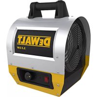
DXH330 - Heating DEWALT - Free user manual and instructions
Find the device manual for free DXH330 DEWALT in PDF.


| Product Type | Forced Air Electric Heater |
| Brand | DeWalt |
| Model | DXH330 |
| Intended Use | Supplemental indoor heating, professional use |
| Heating Power | 11,260 BTU/h (3,300 W) |
| Airflow | 200 ft³/min (5.66 m³/min) |
| Power Supply | 240 V AC, single-phase |
| Adjustable Thermostat | From -5 °C to 35 °C |
| Power Cord Type | 14/3 AWG for length ≤ 3 m |
| Dimensions (L x W x H) | 35.6 x 30.5 x 38.1 cm |
| Weight | 8.6 kg |
| Safety Distances (combustibles) | Front: 1.8 m; sides and rear: 0.6 m; top: 0.6 m |
| Thermal Protection | Overheat Limiter (77 °C) |
| Heating Indicator | Indicator light 'heating in progress' |
| On/Off Switch | Yes, with neon indicator |
| Assembly Required | Yes (handle to attach with 4 screws) |
| Cleaning | Moderate compressed air for interior; dry cloth for exterior |
| Motor Maintenance | No lubrication required (sealed motor) |
| Warranty | 1 year against defects in material and workmanship |
| Customer Service | 855-805-5745 (Mon-Fri, 8:30 AM-5:00 PM EST) |
Frequently Asked Questions - DXH330 DEWALT
User questions about DXH330 DEWALT
0 question about this device. Answer the ones you know or ask your own.
Ask a new question about this device
Download the instructions for your Heating in PDF format for free! Find your manual DXH330 - DEWALT and take your electronic device back in hand. On this page are published all the documents necessary for the use of your device. DXH330 by DEWALT.
USER MANUAL DXH330 DEWALT
If you have questions or comments, contact us.
Electric Forced Air Heater DXH330 and DXH1000TS
READ INSTRUCTIONS CAREFULLY: Read and follow all instructions. Place instructions in a safe place for future reference. Do not allow anyone who has not read these instructions to assemble, adjust or operate the heater.
VEUILLEZ LIRE ATTENTIVEMENT LES INSTRUCTIONS :
Definitions: Safety Guidelines
The definitions below describe the level of severity for each signal word. Please read the manual and pay attention to these symbols.
▲ DANGER: Indicates an imminently hazardous situation which, if not avoided, will result in death or serious injury.
▲ WARNING: Indicates a potentially hazardous situation which, if not avoided, could result in death or serious injury.
CAUTION: Indicates a potentially hazardous situation which, if not avoided, may result in minor or moderate injury.
NOTICE: Indicates a practice not related to personal injury which, if not avoided, may result in property damage.
⚠WARNING: DO NOT OPERATE THIS HEATER UNTIL YOU READ AND UNDERSTAND THIS INSTRUCTION MANUAL FOR SAFETY, OPERATION, AND MAINTENANCE INSTRUCTIONS.
ACAUTION: Use of this heater in any means not described in this manual may cause fire, electric shock, personal injury and/or property damage.
▲CAUTION: This heater is hot when in use. To avoid burns, do not let bare skin touch hot surfaces. Keep combustible materials, such as furniture, pillows, bedding, papers, clothes, and curtains at least 6 feet (1.8 m) from the front of the heater and keep them at least 2 feet (.6 m) away from the sides and rear
ACAUTION: In order to avoid unintended cycling of the heater, always unplug or disconnect unit from power source when not in use.
▲CAUTION: Do not cover the power supply wiring or run the wiring under any carpet or rugs. Arrange cord and connections away from traffic patterns so it is not a tripping hazard.
▲CAUTION: Connect unit to only properly grounded outlets and adequately sized and grounded electrical systems.
▲CAUTION: Do not use this unit with unapproved or under sized electrical connections or wiring. They may overheat and cause a risk of fire.
▲WARNING: Do not use the heater if the unit, plug or cord has visible damage or the unit has malfunctioned. Contact a reputable electrician before reusing.
▲WARNING: Do not expose to wet conditions; unit is intended for indoor use only.
▲WARNING: Unit not intended for use in indoor areas where heater may be exposed to water. Avoid use in bathrooms, laundry rooms or any other areas where the unit may come in contact with water.
▲WARNING: Do not insert or allow any foreign objects to enter the unit via the intake or exhaust vents on the unit. Failure to observe this warning may result in electric shock, fire or damage to the unit.
▲WARNING: To prevent fire do not block either the air intake or exhaust.
▲WARNING: Unit is equipped with internal active electrical components that spark during use. Do not use in areas where fumes from gasoline, paint or other flammable liquids may be present.
▲WARNING: Extreme caution must be used when any heater is used by or near children or invalids and whenever the heater is left operating and unattended.
SAVE THESE INSTRUCTIONS.
Assembly
- Remove the heater and all of the packaging material from the box.
- Check all of the packing material for loose parts and set aside.
- Remove and retain the four handle mounting screws that are threaded into the top shell.
- Thoroughly inspect the heater for damage. If any is found do not contact the place of purchase. Please call the Manufacturer at 855-805-5745.
- Use the four handle mounting screws to fasten the handle to the top of the heater
Note: Do not over tighten the screws as they can crack the handle.
The handle is located in the carton loose be sure not to throw out.
CONTENTS
WARNINGS....2
ASSEMBLY....3
OPERATION 3-4
SPECIFICATIONS....4
CLEARANCES....4
MAINTENANCE....4
TROUBLESHOOTING 5
WIRING DIAGRAMS 6
PARTS LISTS/EXPLODED VIEWS.... 7-10
WARRANTY 11
INSTRUCTIONS FOR ORDERING PARTS 11
Operational Information
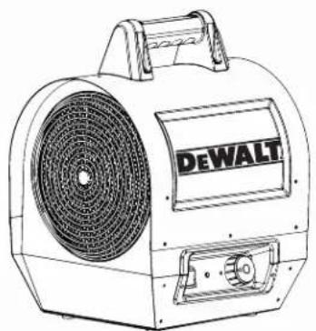
The DeWalt Electric forced air heaters are designed to be used by professionals.
Heat is created by electric current passing through coiled metal elements bringing them up to very high temperatures. The fan then passes room air over the hot elements exchanging cold air for warm.
The air moving over the coils keeps them from reaching temperatures that are not safe for the normal operation of the heater. However it is important to keep all combustible materials and any objects that may be sucked into the fan blades at a safe distance (please refer to the table on the next page for appropriate distances). Make sure that the fan blades remain unobstructed at all times.
Keep unit clean and dust free. Do not block unit intake or exhaust at any time.
Operation
Review and understand all warnings in this manual. Follow all local codes. These heaters are designed to be used with 240v ac only.
Starting Instructions, After Heater Has Been Professionally Wired
- Place the heater on a stable and level surface. Insure clearance to combustibles are observed (see table on this page).
- Turn thermostat counter-clockwise to lowest setting.
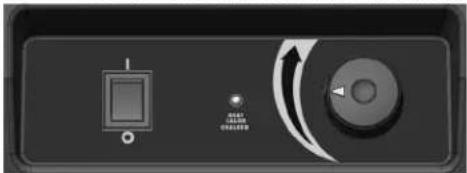
- Depress power switch into the on "I" position.
- Turn thermostat knob up (clockwise) until desired temperature is reached. The heat "on" indicator light will illuminate when the knob reaches a temperature higher than that of the current room.
- The heating element and fan will remain on until the temperature setting is reached. The heating element will cycle on and off as needed. The fan will remain on as long as the control switch is in the on position.
DXH1000TS ONLY: The DXH1000TS is equipped with 10kW/7kW power selection switch, located on the back of the heater in the lower right corner. The (7kW) setting requires a power source of 240Vac/28A on a 30 amp/2 pole circuit breaker. The high (10kW) setting requires a power source of 240Vac/42A on a 50 amp/2 pole circuit breaker. Always confirm your source and power selection switch setting prior to operating the heater.
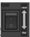
To Stop Heating
- Rotate the thermostat knob to the lowest position.
1a. Let cool for 10 minutes.
- Flip the power switch into the off "O" position.
NOTE: This heater is equipped with an overheat limit switch which may cause the heater to stop. If the power switch is in the on "I" position and the heat indicator light and fan are both off, the overheat limit switch has activated. Check and remove the cause of the overheating before restarting. This can take up to 15 minutes to cool before it can be restarted.
Maintenance
▲ WARNING:
Never attempt to service the heater while the unit is hot, In use, or plugged in. Only qualified service technicians should service these units.
• Thoroughly inspect the unit prior to use.
- Keep heater clean and free of dust and debris.
- The use of an air compressor can be used to blow out the dust from the heater case. Be sure to only use moderate air pressure as to not damage any internal components.
- A soft dry cloth should be used for cleaning of outer shell and handle.
• The fan motor is sealed and does not need to be lubricated.
Specifications
| Model: DXH330 DXH1000TS | ||
| Heat Output BTU/WATTS 1 | 1260/3300 | 22861/6.7kW-4121/10kW |
| Airflow (CFM) 200 325 | ||
| Electrical Supply 240Vac 240Vac | ||
| Thermostat 23 F - 95 F 23 F - 95 F | ||
| Power Cord | Min. 14/3 AWG for 10' or Less | Min. 10/3 AWG for 10' or Less |
| Dimensions: (L"xW"xH") | 14"x12"x15" 23"x13"x16" | |
| Weight (lbs.) | 19 lb. | 37 lb. |
Clearance to Combustibles
| Outlet (Feet) | 6 (1.8m) |
| Rear (Feet) | 2 (.6m) |
| Tom (Feet) | 2 (.6m) |
| Bottom | Non-combustible floor |
ON/OFF HEAT ON INDICATOR LIGHT THERMOSTAT
natural_image
Close-up of a control panel with a square indicator and a rotary knob (no visible text or symbols)FIG. 1
Storage
When not in use, the heater must be disconnected from power source, dusted off and the cord should be loosely wound around the handle.
For service :
Please call Toll-Free 855-805-5745 www.dewalt.com
Our office hours are 8:00 AM – 5:00 PM, EST, Monday through Friday.
Please include the model number, date of purchase, and description of problem in all communication.
WARNING: USE ONLY MANUFACTURER'S REPLACEMENT PARTS. USE OF ANY OTHER PARTS COULD CAUSE INJURY OR DEATH. REPLACEMENT PARTS ARE ONLY AVAILABLE DIRECT FROM THE FACTORY AND MUST BE INSTALLED BY A QUALIFIED SERVICE AGENCY.
Troubleshooting
| Unit does not work • Defective thermostat or wrong thermostat setting• Open circuit breaker or fuse• Thermal overload switch has been tripped• Faulty Connection• Damaged or defective plug or outlet | |
| Unit runs continuously • Defective thermostat or wrong thermostat setting• Heat losses higher than unit capacity (unit undersized) | |
| Elements are on but motor does not rotate • Defective Motor• Blocked fan blades | |
| Enclosure is extremely hot • Defective thermal protection• Blocked air vents• Defective motor | |
| Desired room temperature cannot be reached • One or more elements are defective• Defective thermostat or wrong thermostat setting• Voltage lower than that written on Rate tag• Heat losses higher than unit capacity (unit undersized) | |
| Overheating • Defective thermostat or wrong thermostat setting• Defective Motor | |
| Heater emits a humming sound • Defective motor• Fan blade blocked• Contact defective (10K only) |
Maximum Overload Protection ... 15A/2-Pole
WIRING DIAGRAM Model DXH330
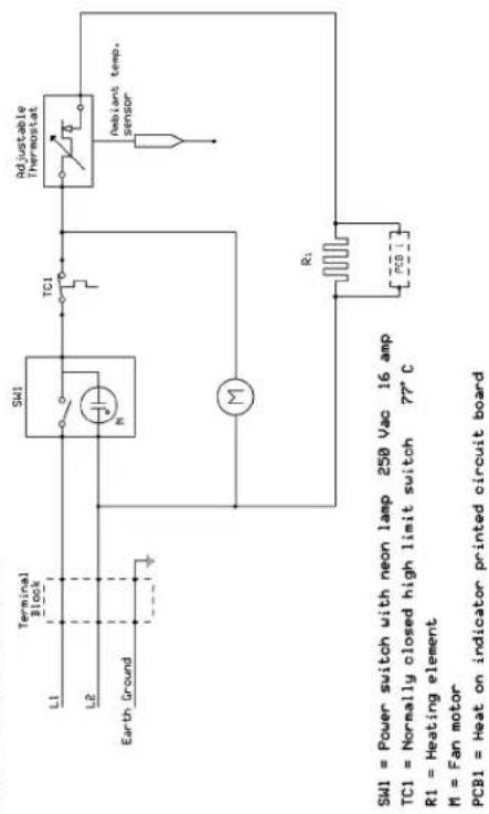
Wiring Diagrams
WIRING DIAGRAM Model DXH1000TS
Maximum Overload Protection ... 58A/2-Pole
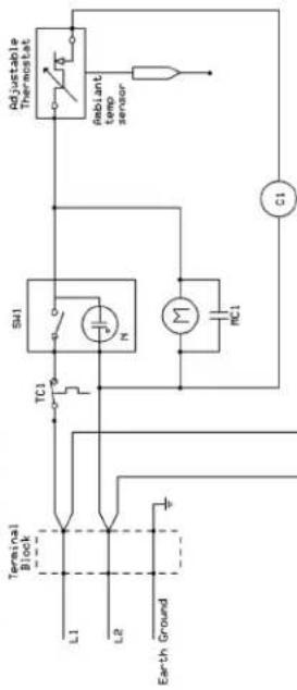
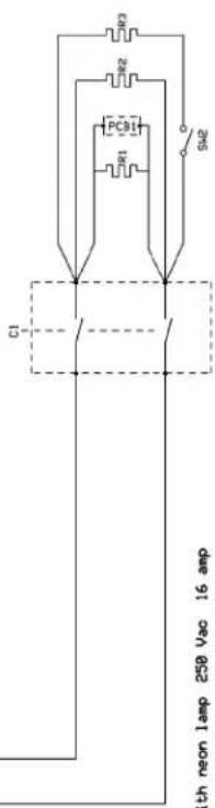
SWI = Power switch with neon lamp 250 Vac 16 amp
SW2 = Full/Partial power switch 250 Vac 16 amp
TCI = Normally closed high limit
C1 = Contactor & contactor
R1 - R3 = Heat
M = Fan motor
MC1 = Motor capacitor
PCB1 = Heat on indicator printed circuit board
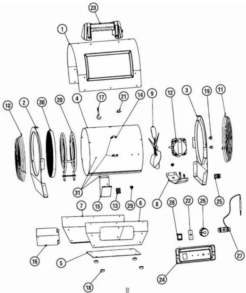
Parts List DXH330
| REF. #......ITEM#......DESCRIPTION | REF. #......ITEM#......DESCRIPTION |
| 1......41037......COVER, TOP, SHELL, OUTER | 16......41051......DOOR, ACCESS |
| 2......N/A......PANEL, FRONT | 17......41029......SUPPORT, HEATING ELEMENT |
| 3......N/A......PANEL, REAR | 18......41030......FOOT, RUBBER |
| 4......410 40......SHIELD, RADIATION, TUBE | 19......41031......CLIP, SENSOR, CAPILLARY TUBE |
| 5......N/A......BASE, PLATE | 20......41052......ELEMENT, HEATING |
| 6......N/A......PANEL, SIDE, LEFT | 21......41032......SWITCH,HIGH LIMIT, 77C |
| 7......N/A......PANEL, SIDE, RIGHT | 22......41053......BOARD, CIRCUIT, HEAT ON,INDICATOR |
| 8......410 44......BRACKET, MOUNT, MOTOR | 23......40656......HANDLE, CARRY |
| 9......410 45......BLADE, FAN | 24......N/A......PANEL, CONTROL, PLASTIC |
| 10......41046......GUARD, GRILL, FRONT | 25......41025......BUSHING, STRAIN, RELIEF |
| 11......41047......GUARD, GRILL, REAR | 26......41027......KNOB, THERMOSTAT, PLASTIC |
| 12......41048......MOTOR, FAN | 27......41034......THERMOSTAT, TEMPERATURE, AMBIANT |
| 13......41049......BLOCK, TERMINAL, WIRING | 28......41035......SWITCH, LIGHTED, ON/OFF |
| 14......N/A......BRACKET, WIRE MOUNT | 29......41036......BUSHING, PLASTIC, WIRE |
| 15......N/A......BLOCK, TERMINAL, BRACKET | 30......N/A......FRONT SCREEN ASSEMBLY |
| 31......41098......RADIATION SHIELD TUBE W/BRACKETS |
▲ WARNING:
Use only manufacturer's replacement parts. Use of any other parts could cause injury or death. Replacement parts are only available direct from the factory and must be installed by a qualified service agency.
For Service
Please call Toll-Free 855-805-5745 www.dewalt.com Our office hours are 8:00 AM – 5:00 PM, EST, Monday through Friday. Please include the model number, date of purchase, and description of problem in all communication.
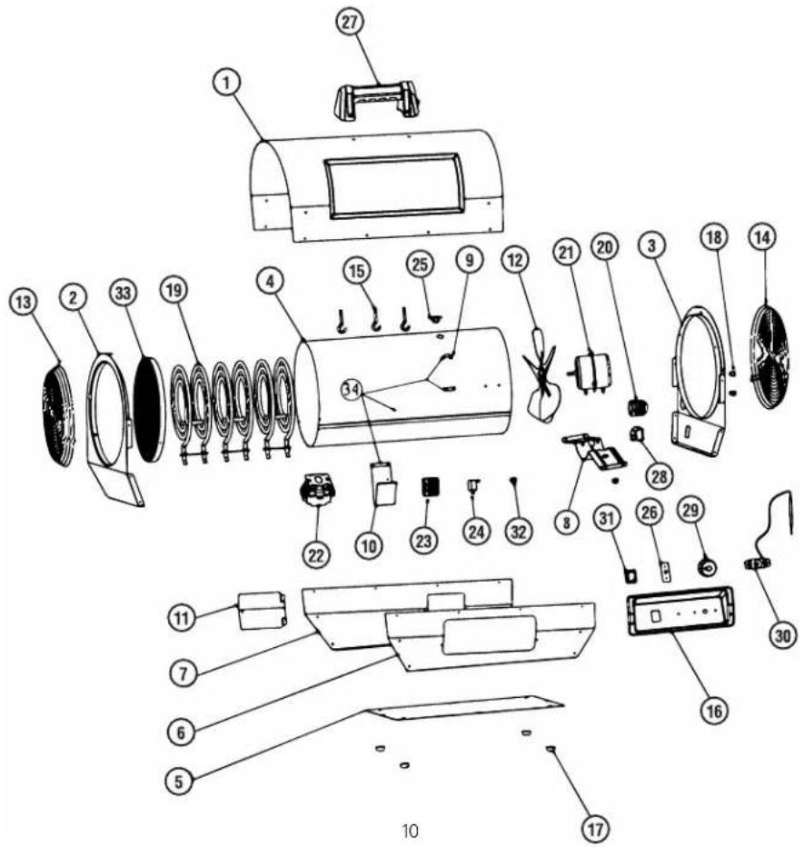
Parts List DXH1000
| REF. #......ITEM#......DESCRIPTION | REF. #......ITEM#......DESCRIPTION |
| 1......41054......COVER, TOP, SHELL, OUTER | 18......41031......CLIP, SENSOR, CAPILLARY TUBE |
| 2......N/A......PANEL, FRONT | 19......41052......ELEMENT, HEATING |
| 3......N/A......PANEL, REAR | 20......41066......BUSHING, STRAIN, RELIEF |
| 4......41057......SHIELD, RADIATION, TUBE | 21......41067......MOTOR, FAN |
| 5......41058......BASE, PLATE | 22......41068......CONTACTOR, ELEMENT, HEATING |
| 6......N/A......PANEL, SIDE, LEFT | 23......41069......BLOCK, TERMINAL, WIRING |
| 7......N/A......PANEL, SIDE, RIGHT | 24......41070......CAPACITOR, MOTOR, STARTER |
| 8......41061......BRACKET, MOUNT, MOTOR | 25......41032......SWITCH, HIGH LIMIT, 77C |
| 9......N/A......BRACKET, WIRE MOUNT | 26......41053......BOARD, CIRCUIT, HEAT ON, INDICATOR |
| 10......N/A......BLOCK, TERMINAL, BRACKET | 27......40656......HANDLE, CARRY |
| 11......41051......DOOR, ACCESS | 28......41035......SWITCH, LIGHTED, 10KW/7KW |
| 12......41063......BLADE, FAN | 29......41027......KNOB, THERMOSTAT, PLASTIC |
| 13......41064......GUARD, GRILL, FRONT | 30......41034......THERMOSTAT, TEMPERATURE, AMBIENT |
| 14......41065......GUARD, GRILL, REAR | 31......41035......SWITCH, LIGHTED, ON/OFF |
| 15......41029......SUPPORT, HEATING ELEMENT | 32......41036......BUSHING, PLASTIC, WIRE |
| 16......N/A......PANEL, CONTROL, PLASTIC | 33......41062......FRONT SCREEN ASSEMBLY |
| 17......41030......FOOT, RUBBER | 34......41099......RADIATION SHIELD TUBE W/BRACKETS |
WARNING:
Use only manufacturer's replacement parts. Use of any other parts could cause injury or death. Replacement parts are only available direct from the factory and must be installed by a qualified service agency.
For Service
Please call Toll-Free 855-805-5745 www.dewalt.com
Our office hours are 8:00 AM – 5:00 PM, EST, Monday through Friday.
Please include the model number, date of purchase, and description of problem in all communication.
DXH1000TS
DEWALT®
INSTRUCTION MANUAL
Electric Forced-Air Heater DXH330, DXH1000TS
natural_image
Line drawing of a DeWALT air purifier with fan and vent slots (no text or symbols on body)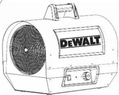
natural_image
Line drawing of a DeWALT air purifier with fan and vent slots (no text or symbols on body)Warning:
Use only manufacturer's replacement parts. Use of any other parts could cause injury or death. Replacement parts are only available direct from the factory and must be installed by a qualified service agency.
PARTS ORDERING INFORMATION:
PURCHASING: Accessories may be purchased at any DeWalt® local dealer or direct from the factory
FOR INFORMATION REGARDING SERVICE:
Please call Toll-Free 855-805-5745
www.dewalt.com
Our office hours are 8:00 AM - 5:00 PM, EST, Monday through Friday.
Please include the model number, date of purchase, and description of problem in all communication.
LIMITED WARRANTY:
DeWalt ^® warrants its heaters and accessories to be free from defects in material and workmanship for a period of 1 year from date of purchase. DeWalt ^® will repair or replace this product free of charge if it has been proven to be defective within the 1-year period, and is returned at customer expense with proof of purchase to DeWalt ^® within the warranty period.
DEWALT®, GUARANTEED TOUGH® and the yellow and black color scheme are trademarks of the DEWALT Industrial Tool Co., used under license. ©2015 DEWALT. EGI/Enerco Group Inc. Under license from Dewalt Industrial Tool Co.
If you have questions or comments, contact us.
MANUEL D'INSTRUCTIONS
Electric Forced Air Heater DXH330 and DXH1000TSp
READ INSTRUCTIONS CAREFULLY: Read and follow all instructions. Place instructions in a safe place for future reference. Do not allow anyone who has not read these instructions to assemble, adjust or operate the heater.
natural_image
Close-up of a control panel with a square indicator and circular dial (no text or symbols visible)FIG. 1
Entreposage
DEWALT®
MANUEL D'INSTRUCTIONS
natural_image
Line drawing of a DeWALT air purifier with fan and vent slots (no text or symbols on body)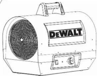
natural_image
Line drawing of a DeWALT air purifier with fan and vent (no text or symbols on body)AVERTISSEMENT :
If you have questions or comments, contact us.
MANUEL D'INSTRUCTIONS
Electric Forced Air Heater DXH330 and DXH1000TS
READ INSTRUCTIONS CAREFULLY: Read and follow all instructions. Place instructions in a safe place for future reference. Do not allow anyone who has not read these instructions to assemble, adjust or operate the heater.
VEUILLEZ LIRE ATTENTIVEMENT LES INSTRUCTIONS :
natural_image
Close-up of a control panel with a square indicator and circular dial (no readable text or symbols)FIG. 1
Almacenamiento
Lista de partes DXH1000
| REF......ARTÍCULO......DESCRIPCIÓN | REF......ARTÍCULO......DESCRIPCIÓN |
| 1......41054......CUBIERTA, SUPERIOR, EXTERNA | 18......41031......PINZA, SENSOR, TUBO CAPILAR |
| 2......N/A......PANEL, FRONTAL | 19......41052......ELEMENTO, CALEFACTOR |
| 3......N/A......PANEL, TRASERO | 20......41066......CASQUILLO, PRENSACABLES |
| 4......41057......PANTALLA, RADIACIÓN, TUBO | 21......41067......MOTOR, VENTILADOR |
| 5......41058......BASE, PLACA | 22......41068......CONTACTOR, ELEMENTO, CALEFACTOR |
| 6......N/A......PANEL, LATERAL, IZQUIERDO | 23......41069......BLOQUE, TERMINAL, CABLEADO |
| 7......N/A......PANEL, LATERAL, DERECHO | 24......41070......CAPACITOR, MOTOR, ARRANCADOR |
| 8......41061......SOPORTE, MONTAJE, MOTOR | 25......41032......INTERRUPTOR, LÍMITE SUPERIOR, 77 °C |
| 9......N/A......SOPORTE, MONTAJE DE CABLES | 26......41053......PLACA, CIRCUITO, CALEFACCIÓN ENCENDIDA, INDICADOR |
| 10......N/A......BLOQUE, TERMINAL, SOPORTE | 27......40656......ASA, TRANSPORTACIÓN |
| 11......41051......PUERTA, ACCESO | 28......41035......INTERRUPTOR, ENCENDIDO, 10KW/7KW |
| 12......41063......ASPA, VENTILADOR | 29......41027......CONTROL, TERMOSTATO, PLÁSTICO |
| 13......41064......PROTECTOR, REJILLA, FRONTAL | 30......41034......TERMOSTATO, TEMPERATURA, AMBIENTE |
| 14......41065......PROTECTOR, REJILLA, TRASERO | 31......41035......INTERRUPTOR, ENCENDIDO, ENCENDIDO/APAGADO |
| 15......41029......SOPORTE, ELEMENTO CALEFACTOR | 32......41036......CASQUILLO, PLÁSTICO, CABLE |
| 16......N/A......PANEL, CONTROL, PLÁSTICO | 33......41062......ASAMBLEA DE PANTALLA FRONTAL |
| 17......41030......PATA, GOMA | 34......41099......RADIACIÓN TUBO SHIELD CON SOPORTES |
ADVERTENCIA:
DEWALT®
natural_image
Line drawing of a portable air purifier with 'DEWALT' branding on the front panel (no additional text or symbols)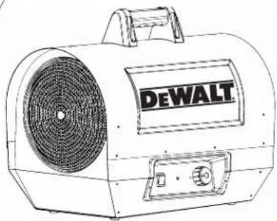
natural_image
Line drawing of a DeWALT air purifier with fan and vent slots (no text or symbols on body)Advertencia:



- Definitions: Safety Guidelines
- ⚠WARNING: DO NOT OPERATE THIS HEATER UNTIL YOU READ AND UNDERSTAND THIS INSTRUCTION MANUAL FOR SAFETY, OPERATION, AND MAINTENANCE INSTRUCTIONS.
- Assembly
- CONTENTS
- Operational Information
- Operation
- Starting Instructions, After Heater Has Been Professionally Wired
- To Stop Heating
- Maintenance
- ▲ WARNING:
- Storage
- For service :
- For Service
- WARNING:
- DEWALT®
- INSTRUCTION MANUAL
- Electric Forced-Air Heater DXH330, DXH1000TS
- PARTS ORDERING INFORMATION:
- FOR INFORMATION REGARDING SERVICE:
- LIMITED WARRANTY:
- Entreposage
- MANUEL D'INSTRUCTIONS
- AVERTISSEMENT :
- Almacenamiento
- ADVERTENCIA:
Brand : DEWALT
Model : DXH330
Category : Heating