
KWCU265HSS - Range hood KITCHENAID - Free user manual and instructions
Find the device manual for free KWCU265HSS KITCHENAID in PDF.
| Brand | KitchenAid |
| Model | KWCU265HSS |
| Product Type | Wall-mounted range hood |
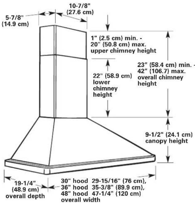
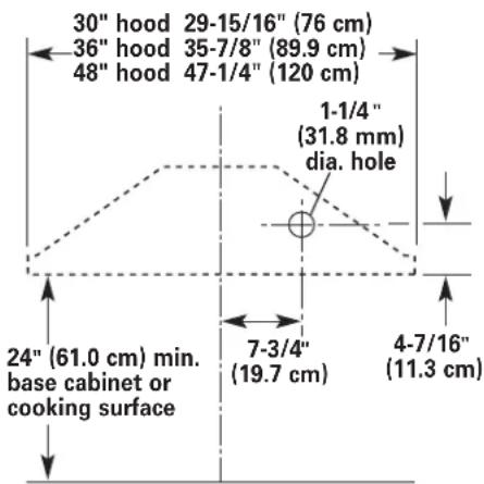
| Width (30-inch model) | 76 cm (29 15/16 in) |
| Width (36-inch model) | 89.9 cm (35 3/8 in) |
| Width (48-inch model) | 120 cm (47 1/4 in) |
| Overall depth | 48.9 cm (19 1/4 in) |
| Height of the hood | 24.1 cm (9 1/2 in) |
| Total chimney height (min) | 58.4 cm (23 in) |
| Total chimney height (max) | 106.7 cm (42 in) |
| Power supply | 120 V, 60 Hz, AC, 15 A |
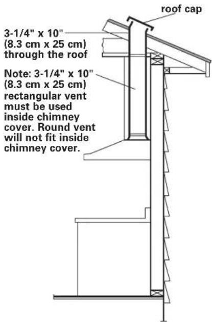
| Accepted duct types | Rectangular 8.3 x 25 cm or round ø 17.8 / 20.3 / 22.9 cm |
| Maximum duct length (rect. 8.3x25 cm) | 10.7 m (35 ft) |
| Lighting | Fluorescent lamp F33-15W-T8 with S2 starter |
| Filters | Washable metal filters (dishwasher-safe); charcoal filter option |
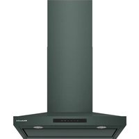
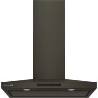
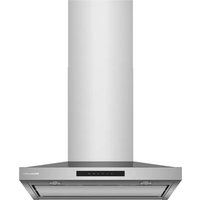
| Material | Stainless steel |
| Controls | Light and fan switches + speed control |
| Number of speeds | Variable (speed control) |
| Installation | Wall mount, external exhaust (roof or wall) possible recirculation |
| Recommended maintenance | Frequent cleaning of filters and surfaces with mild detergent |
| Warranty | 1-year limited (parts and labor) |
Frequently Asked Questions - KWCU265HSS KITCHENAID
User questions about KWCU265HSS KITCHENAID
0 question about this device. Answer the ones you know or ask your own.
Ask a new question about this device
Download the instructions for your Range hood in PDF format for free! Find your manual KWCU265HSS - KITCHENAID and take your electronic device back in hand. On this page are published all the documents necessary for the use of your device. KWCU265HSS by KITCHENAID.
USER MANUAL KWCU265HSS KITCHENAID
Installation Instructions and Use and Care Guide
30" (76.2 cm)
36" (91.4 cm)
48" (121.9 cm)
Wall-Mount Canopy Range Hood
IMPORTANT:
Read and save these instructions.
IMPORTANT:
Installer: Leave Installation Instructions with the homeowner.
Homeowner: Keep Installation Instructions for future reference.
Save Installation Instructions for local electrical inspector's use.
Quick Reference
Table of Contents:
Pages
2 Before you start
3 Product dimensions
3 Cabinet dimensions
3 Venting requirements
5 Electrical requirements
7 Installation steps
8 Use and Care Information
9 Wiring diagram
9 Accessories
10 Warranty
12 Requesting Assistance or Service


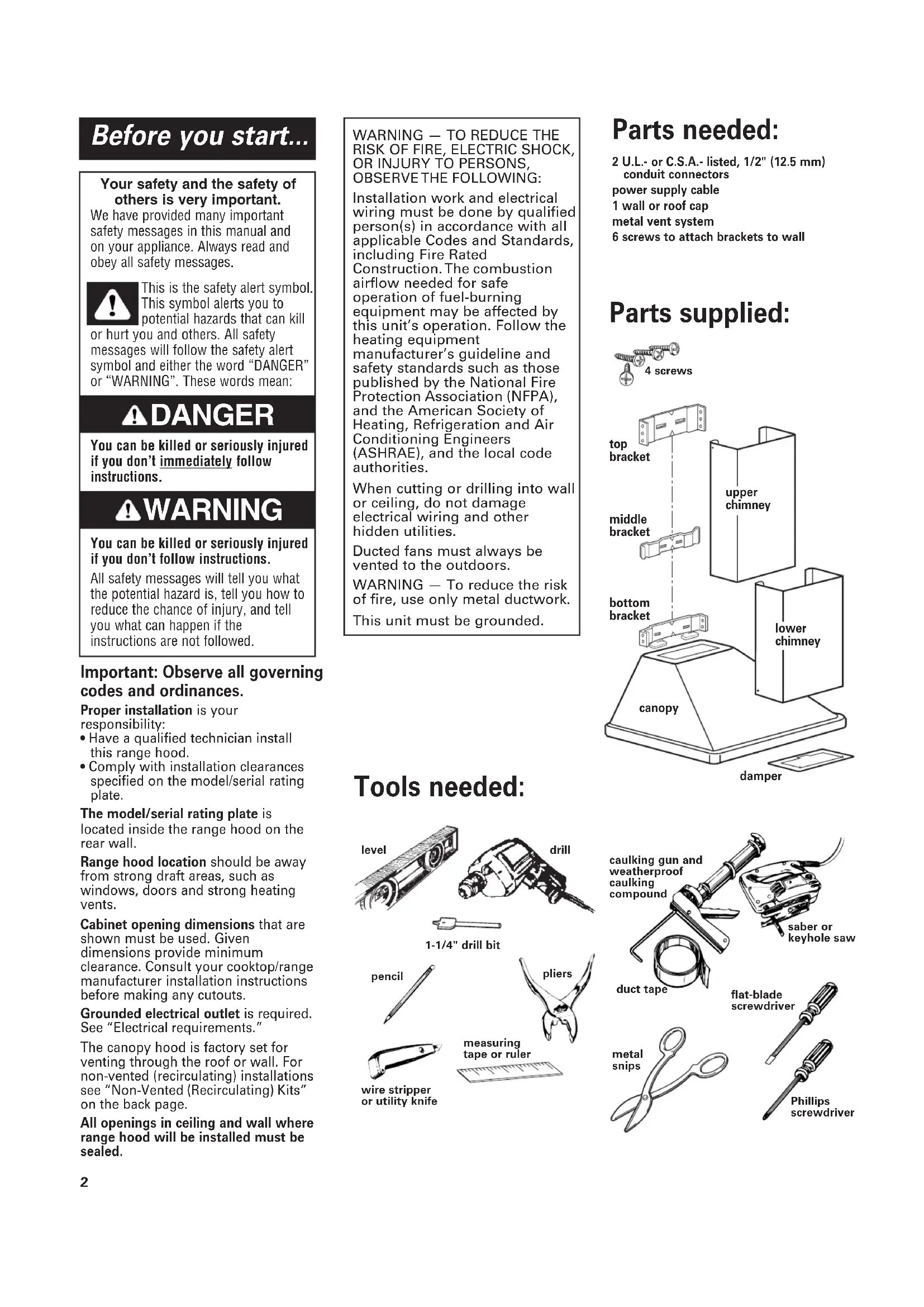
Before you start...
Your safety and the safety of others is very important.
We have provided many important safety messages in this manual and on your appliance. Always read and obey all safety messages.

This is the safety alert symbol. This symbol alerts you to potential hazards that can kill
or hurt you and others. All safety messages will follow the safety alert symbol and either the word “DANGER” or “WARNING”. These words mean:
! DANGER
You can be killed or seriously injured if you don't immediately follow instructions.
WARNING
You can be killed or seriously injured if you don't follow instructions.
All safety messages will tell you what the potential hazard is, tell you how to reduce the chance of injury, and tell you what can happen if the instructions are not followed.
Important: Observe all governing codes and ordinances.
Proper installation is your responsibility:
- Have a qualified technician install this range hood.
- Comply with installation clearances specified on the model/serial rating plate.
The model/serial rating plate is located inside the range hood on the rear wall.
Range hood location should be away from strong draft areas, such as windows, doors and strong heating vents.
Cabinet opening dimensions that are shown must be used. Given dimensions provide minimum clearance. Consult your cooktop/range manufacturer installation instructions before making any cutouts.
Grounded electrical outlet is required. See "Electrical requirements."
The canopy hood is factory set for venting through the roof or wall. For non-vented (recirculating) installations see "Non-Vented (Recirculating) Kits" on the back page.
All openings in ceiling and wall where range hood will be installed must be sealed.
WARNING — TO REDUCE THE RISK OF FIRE, ELECTRIC SHOCK, OR INJURY TO PERSONS, OBSERVE THE FOLLOWING:
Installation work and electrical wiring must be done by qualified person(s) in accordance with all applicable Codes and Standards, including Fire Rated Construction. The combustion airflow needed for safe operation of fuel-burning equipment may be affected by this unit's operation. Follow the heating equipment manufacturer's guideline and safety standards such as those published by the National Fire Protection Association (NFPA), and the American Society of Heating, Refrigeration and Air Conditioning Engineers (ASHRAE), and the local code authorities.
When cutting or drilling into wall or ceiling, do not damage electrical wiring and other hidden utilities.
Ducted fans must always be vented to the outdoors.
WARNING — To reduce the risk of fire, use only metal ductwork.
This unit must be grounded.
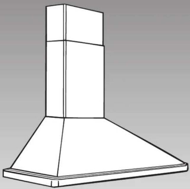
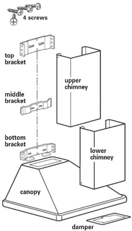
Parts needed:
6 screws to attach brackets to wall
Parts supplied:
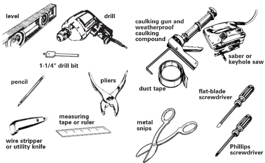
Tools needed:
Cabinet dimensionsProd
Venting requirements
Vent system must terminate to the outside.
Do not terminate the vent system in an attic or other enclosed area.
Do not use 4 inch (10.2 cm) laundry-type wall caps.
Use metal vent only. Rigid metal vent is recommended. Do not use plastic or metal foil vent.
For the most efficient and quiet operation:
• The size of the vent should be uniform.
- Use no more than three 90° elbows.
- Make sure there is a minimum of 24" (61 cm) of straight vent between the elbows if more than one elbow is used.
- Do Not install two elbows together.
- The length of vent system and number of elbows should be kept to a minimum to provide efficient performance.
- The vent system must have a damper. If roof or wall cap has a damper, Do Not use damper supplied with the range hood.
- Use duct tape to seal all joints in the vent system.
- Use caulking to seal exterior wall or roof opening around the cap.
Determine which venting method is best for your application and follow "Preparation" under "Installation steps" on Page 5.
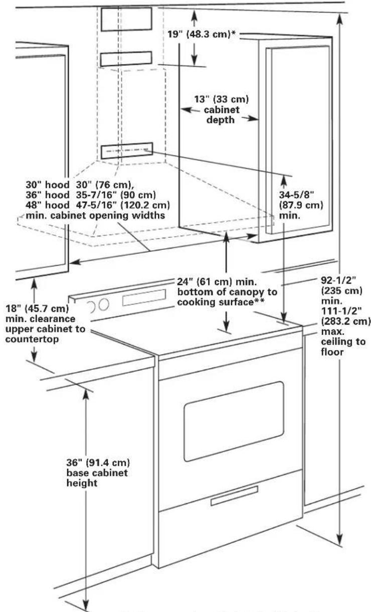
* If the canopy hood is installed higher than 24" (61 cm) above the cooking surface, the middle bracket must be installed at the bottom point of the upper chimney sleeve.
** If the canopy hood is mounted higher than 24" (61 cm) above cooking surface, depending on ceiling height, upper chimney may need to be cut.
Venting methods
This canopy range hood is factory set for venting through the roof or wall. For non-vented (recirculating) installations, see "Non-Vented (Recirculating) Kits" on back page.
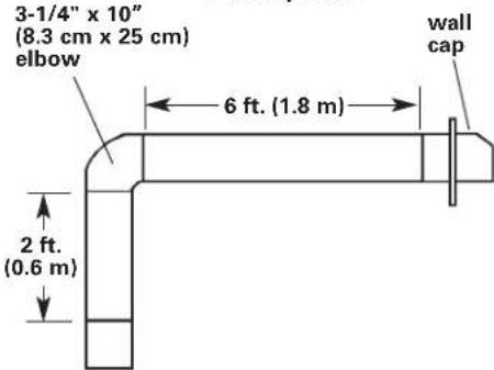
Vent system needed for installation is not included. 3-1/4" x 10" (8.3 cm x 25 cm) rectangular, 7" (17.8 cm) round, 8" (20.3 cm) round or 9" (22.9 cm) round vent may be used. The hood exhaust opening is 3-1/4" x 10" (8.3 cm x 25 cm).
Vent system can terminate either through the roof or wall. To vent through a wall, a 90° elbow is needed.
The vent system length should not exceed the lengths shown in the chart below.
| Vent size Maximum length |
| 3-1/4" x 10" 35 ft. (10.7 m)(8.3 cm x 25 cm) |
| 7" (17.8 cm) round 40 ft. (12.2 m) |
| 8" (20.3 cm) round 50 ft. (15.2 m) |
| 9" (22.9 cm) round 60 ft. (18.3 m) |
Vertical roof venting
Horizontal wall venting

Calculating the vent system length
To calculate the length of the system you need, add the equivalent feet for each vent piece used in the system.
| Vent Piece 3-1/4" x 10" (8.3 cm x 25 cm) 7" (17.8 cm), 8" (20.3 cm) Rectangular or 9" (22.9 cm) Round | ||
| 45° elbow 7.0 feet | (2.1 m) 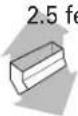 | (0.8 cm) 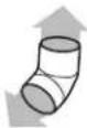 |
| 90° elbow 5.0 feet | (1.5 m) 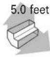 | (1.5 m) 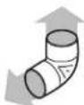 |
| 90° flat elbow | 12.0 feet (3.7 m) 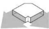 | |
| transition to round | 5.0 feet (1.5 m)  | |
| wall cap | 0.0 feet (0.0 m)  | |
3-1/4" x 10" (8.3 cm x 25 cm)
vent system
Maximum length = 35 ft. (10.7 m)
1 - 90° elbow = 5 ft. (1.5 m)
8 ft. (2.4 m) straight = 8 ft. (2.4 m)
1 - wall cap = 0 ft. (0 m)
Length of 3-1/4" x 10"
(8.3 cm × 25 cm)
system = 13 ft. (4 m)
Note: Flexible vent is Not recommended.
If it is used, each foot of flexible vent used is equivalent to two feet (61 cm) of straight metal vent when calculating the vent system length. (Example: A flexible elbow equals two standard elbows.)
Electrical requirements
Important: Observe all governing codes and ordinances.
It is the customer's responsibility:
- To contact a qualified electrical installer.
- To assure that the electrical installation is adequate and in conformance with National Electrical Code, ANSI/NFPA 70 — latest edition*, or CSA Standards C22.1-94, Canadian Electrical Code, Part 1 and C22.2 No.0-M91 - latest edition** and all local codes and ordinances.
If codes permit and a separate ground wire is used, it is recommended that a qualified electrician determine that the ground path is adequate.
A 120-volt, 60-Hz, AC-only, fused electrical system is required on a
separate 15-amp circuit, fused on both sides of the line.
Do not ground to a gas pipe.
Check with a qualified electrician if you are not sure range hood is properly grounded.
Do not have a fuse in the neutral or ground circuit.
IMPORTANT:
Save Installation Instructions for electrical inspector's use.
The range hood must be connected with copper wire only.
The range hood should be connected directly to the fused disconnect (or circuit breaker) box through flexible armored or nonmetallic sheathed copper cable. A U.L.- or C.S.A.-listed strain relief must be provided at each end of the power supply cable. Wire sizes (COPPER
WIRE ONLY) and connections must conform with the rating of the appliance as specified on the model/serial rating plate.
Wire sizes must conform to the requirements of the National Electrical Code ANSI/NFPA 70 — latest edition*, or CSA Standards C22.1-94, Canadian Electrical Code Part 1 and C22.2 No. 0-M91 - latest edition** and all local codes and ordinances.
A U.L.- or C.S.A.-listed conduit connector must be provided at each end of the power supply cable (at the range hood and at the junction box).
Copies of the standards listed may be obtained from:
* National Fire Protection Association Batterymarch Park Quincy, Massachusetts 02269
** CSA International 8501 East Pleasant Valley Road Cleveland, Ohio 44131-5575
Installation steps
Preparation
Do not cut a joist or stud unless absolutely necessary. If a joist or stud must be cut, then a supporting frame must be constructed.
Before making cutouts, make sure there is proper clearance within the ceiling or wall for exhaust vent.
-
If possible, disconnect and move freestanding or slide-in range from cabinet opening to provide easier access to rear wall. Otherwise put a thick, protective covering over countertop, cooktop or range to protect from damage or dirt. Select a flat surface for assembling the unit. Cover that surface with a protective covering and place all canopy hood parts and hardware in it.
-
Determine and mark the centerline on the wall where the canopy hood will be installed.
-
Attach the lower bracket securely to the wall at the height shown. The dimension shown on page 3 is for mounting the canopy hood 24" (61 cm) above cooking surface. The lower bracket must be mounted with the
flanges on the bottom of the bracket so that the canopy hood will hang from them.
If a backsplash is to be used with this canopy hood, it MUST be installed before the canopy hood. Installation instructions for the backsplash are supplied with the backsplash kit. The height of the backsplash will determine the height of the bottom edge of the canopy hood.
- Attach the middle and upper brackets securely to the wall. The upper bracket should be installed about 1/8" (3 mm) away from the ceiling. The middle bracket (bright metal) must be installed with ends touching the wall and the curves facing outward.
Note: If the canopy hood is installed more than 24" (61 cm), the middle bracket must be installed at the bottom point of the upper chimney sleeve.
It may be necessary to cut the upper chimney. Be careful not to damage or bend upper chimney when cutting.
- Determine and make all necessary cuts in the wall for the vent system. Install the vent system before the canopy hood. See venting methods on page 4.
- Determine the required height for the power supply cable and cut a 1-1/4" (3.2 cm) hole at this location. Run wire through hole according to the National Electrical Code or CSA Standards and local codes and ordinances. There must be enough power supply cable from the fused disconnect (or circuit breaker) box to make the connection in the hood's electrical box.
Use caulking to seal all openings.
Do Not turn on power until installation is completed.
-
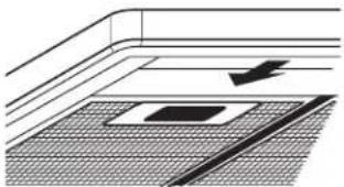
Press on handle in front of filters to release filters from range hood canopy. Remove filters and set aside.
-
Remove the terminal box cover from the canopy hood. Remove the power supply cable knockout using a flat-blade screwdriver. Attach conduit connector into power supply cable opening so that conduit connector clamping screws are inside of canopy hood.
WARNING
Excessive Weight Hazard Use two or more people to move and install range hood. Failure to do so can result in back or other injury.
-
Align the "T" area of the canopy hood slots with the lower bracket flanges. Push hood toward wall. Gently lower the hood making sure the lower bracket flanges are fully inserted into the slots. Check that the hood is secure on the lower bracket. Feed enough power supply cable through conduit connector to make electrical connections.
-
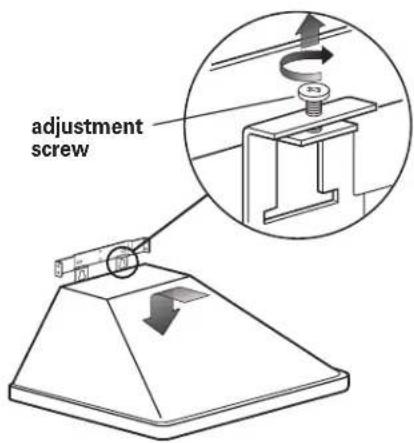
Level the hood and adjust hood height by turning the adjusting screws.
Electrical connection
WARNING

Electrical Shock Hazard Disconnect power before making electrical connections.
Connect ground wire to green ground screw in terminal box.
Failure to do so can result in death or electrical shock.
- Make electrical connection:
Connect the power supply cable to hood terminal box through the U.L.- or C.S.A.-listed conduit connector.
√ Connect the white wire of the power supply cable with the white lead in the hood using a twist-on connector; connect the black wire of the power supply cable with the black lead in the hood using a twist-on connector.
☑ Connect the power supply green (green and yellow) ground wire under the green, ground screw.
☑ Tighten conduit connector screws.
√ Replace the terminal box cover.
Install chimney sections
- If roof or wall cap does not have a damper, attach damper to exhaust opening on top of the canopy using two Phillips-head screws. Connect vent system to damper or hood and seal all connections with duct tape.
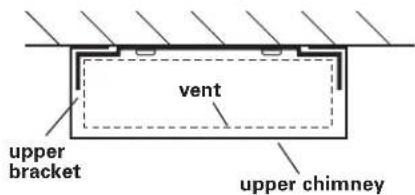
- Carefully fit the upper chimney rear flanges behind the upper and middle bracket.
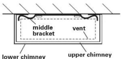
- Carefully fit the lower chimney rear flanges behind the upper chimney flanges on the middle bracket and behind the lower bracket.
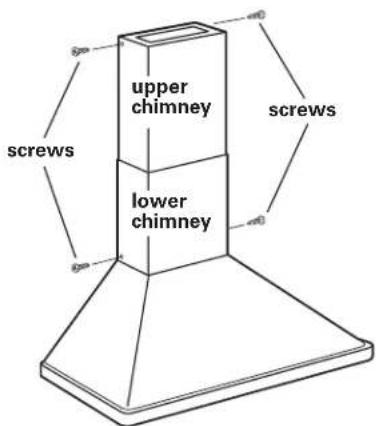
- When upper and lower chimney sections are in final position, attach the top of the upper chimney and the bottom of the lower chimney to the top and bottom brackets.
Check operation
-
Place filters in canopy openings so rear edge is over flange. Press filters up into position.
-
Turn power on.
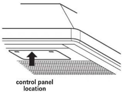
- The canopy hood controls are located in a grey panel on underside of the canopy. To open the panel, press on the front edge of panel and release. The control panel will drop down.
- Check the operation of the range hood:
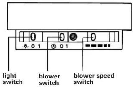
√ Move light switch to "1" position. The light should turn on.
√ Move blower switch to "1" position. The blower should operate.
√ Move the blower speed switch to the far left; blower speed should be LOW. Move blower speed to right; blower speed should gradually increase until you reach HIGH speed at far right.
√ Move blower and light switches to "0" position to turn blower and light off.
If range hood does not operate:
☑ Check that the circuit breaker is not tripped or the house fuse blown.
√ Disconnect power supply. Check that wiring is correct.
To get the most efficient use from your new range hood, read the "Use and Care Information" section. Keep your KitchenAid Installation Instructions and Use and Care Guide close to range hood for easy reference.
Use and Care Information
WARNING — TO REDUCE THE RISK OF FIRE, ELECTRIC SHOCK, OR INJURY TO PERSONS, OBSERVE THE FOLLOWING:
Use this unit only in the manner intended by the manufacturer. If you have questions, contact the manufacturer. Before servicing or cleaning unit, switch power off at service panel and lock switch power off at service panel and lock service panel to prevent power from being switched on accidentally. When the service disconnecting means cannot be locked, securely fasten a prominent warning device such as a tag to the service panel.
CAUTION: For general ventilating use only. Do not use to exhaust hazardous or explosive materials and vapors.
WARNING — TO REDUCE THE RISK OF A RANGE TOP GREASE FIRE:
Never leave surface units unattended at high settings. Boilovers cause smoking and greasy spillovers that may ignite. Heat oils slowly on low or medium settings.
Always turn hood ON when cooking at high heat or when cooking flaming foods.
Clean ventilating fans frequently. Grease should not be allowed to accumulate on fan or filter.
Use proper pan size. Always use cookware appropriate for the size of the surface element.
WARNING — TO REDUCE THE RISK OF INJURY TO PERSONS IN THE EVENT OF A RANGE TOP GREASE FIRE, OBSERVE THE FOLLOWING:
SMOTHER FLAMES with a close-fitting lid, cookie sheet, or metal tray, then turn off the burner. BE CAREFUL TO PREVENT BURNS. If the flames do not go out immediately, EVACUATE AND CALL THE FIRE DEPARTMENT.
NEVER PICK UP A FLAMING PAN — You may be burned.
DO NOT USE WATER, including wet dishcloths or towels — a violent steam explosion will result. Use an extinguisher ONLY if:
You know you have a Class ABC extinguisher, and you already know how to operate it.
The fire is small and contained in the area where it is started.
The fire department is being called.
You can fight the fire with your back to an exit.
This fan suitable for use with solid-state speed controls.
Operation
The canopy hood is designed to remove smoke, cooking vapors and odors from the cooktop area. For best results, start the hood before cooking and allow it to operate several minutes after the cooking is complete to clear all smoke and odors from the kitchen.
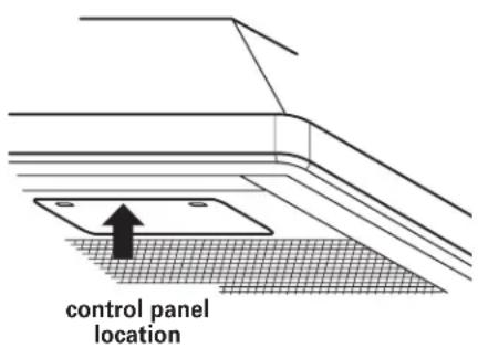
Opening the canopy hood control panel:
The hood controls are located in a grey panel on the underside of the canopy. To open the panel, press on the front edge of panel and release. The control panel will drop down.
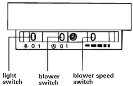
Operating the light:
ON: Move the light switch to the "1" position.
OFF: Move the light switch to the "0" position.
Operating the blower:
ON: Move the blower switch to the "1" position.
OFF: Move the blower switch to the "0" position.
Adjusting the blower speed:
The blower has variable speed control.
Move the switch to the far left for LOW speed and to the far right for HIGH speed.
Closing the range hood control panel:
Push up on the front edge of the control panel. The control panel will slide up into the canopy.
Cleaning
Filters:
The filters should be washed frequently. Place metal filters in dishwasher or hot detergent solution to clean.
Exterior surfaces:
Clean the range hood with a mild detergent and soft cloth. Do Not use abrasive cleanser or steel wool pads.
Maintenance
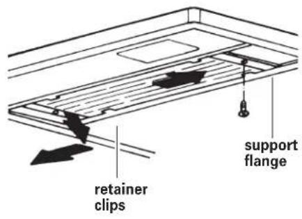
Replacing the light bulb:
This range hood uses fluorescent lamp type F33-15W-T8 and starter type 52.
Remove the retainer clips from both ends of the light cover. Carefully slide the cover all the way to the right. Then lower the left end of the glass below the support flange and remove the glass by sliding it back from the left.
Install a new fluorescent light bulb. Position the right end of the light cover over the flange and slide the cover all the way to the right. Position the left end of the light cover over the flange and slide the cover back to left. Reinstall the retainer clips.
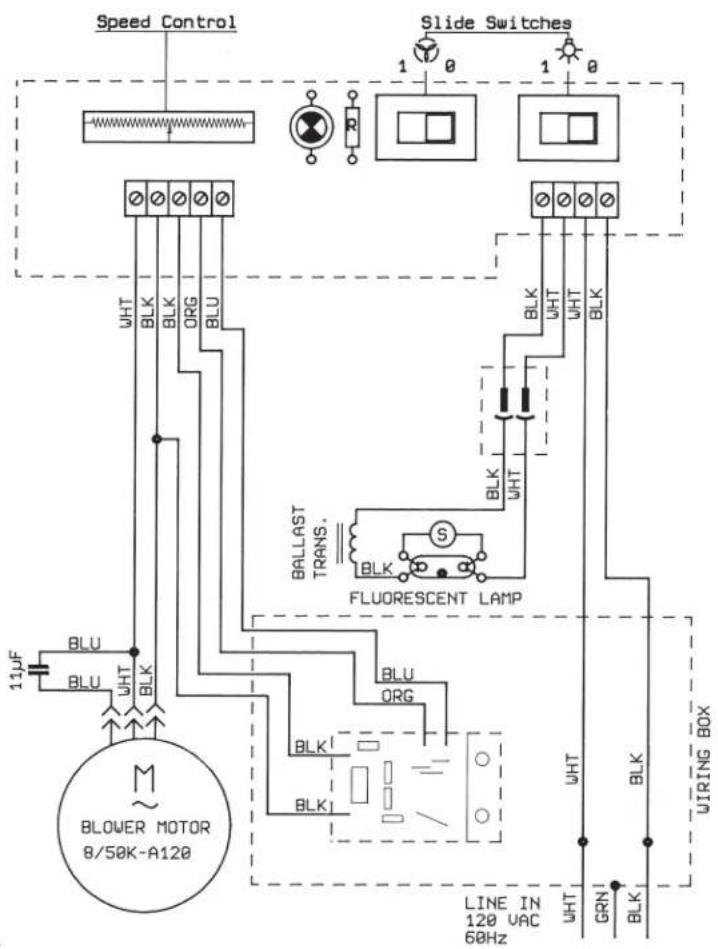
Wiring diagram
For assistance:
If you have questions about operating, cleaning or maintaining your range hood:
√√ Call the KitchenAid Consumer Assistance Center, 1-(800) 422-1230.
If you need service:
Maintain the quality built into your appliance by calling a KitchenAid-authorized service company. To obtain the name and number of an authorized service company:
√Contact the dealer from whom you purchased the appliance;
√Look in the Yellow Pages of your telephone directory under "Appliances — Household — Major — Service and Repair;"
√ Call the KitchenAid Consumer Assistance Center, 1-(800) 422-1230.
Accessories
available from your dealer
Note: Instructions are included with each kit.
Backsplash*: Must be installed before hood is installed. Stainless steel only. Part No. 8171295 30" (76.2 cm) Part No. 4378615 36" (91.4 cm) Part No. 8171296 48" (121.9 cm)
Utensil Bar: Stainless steel only Part No. 4378619 (side) 15" (38 cm) long Part No. 8171299 (back) 30" (76 cm) long Part No. 4378618 (back) 35-3/8" (90 cm) long
Charcoal Filters: Part No. 4378623 (2 per pkg.)
Non-Vented (Recirculating) Kits*: Part No. 4378621 (stainless steel) Part No. 4378622 (white) Part No. 8171290 (biscuit)
Wire Rack: Chrome only Part No. 8171297 30" (76.2 cm) Part No. 4378616 36" (91.4 cm) Part No. 8171298 48" (121.9 cm)
Rack Hanger Kit: Chrome only Part No. 4378617
Chimney Extensions*: Part No. 8171313 (stainless steel) Part No. 8171315 (biscuit) Part No. 8171314 (white)
*These instructions must be read before starting the canopy hood installation.
KITCHENAID® VENTILATION WARRANTY
ONE YEAR LIMITED WARRANTY
For one year from the date of purchase, when this major appliance is operated and maintained according to instructions attached to or furnished with the product, KitchenAid or KitchenAid Canada (hereafter "KitchenAid") will pay for factory specified parts and repair labor to correct defects in materials or workmanship. Service must be provided by a KitchenAid designated service company.
ITEMS KITCHENAID WILL NOT PAY FOR
- Service calls to correct the installation of your major appliance, to instruct you how to use your major appliance, to replace or repair house fuses or to correct house wiring or plumbing.
- Service calls to repair or replace appliance light bulbs, air filters or water filters. Those consumable parts are excluded from warranty coverage.
- Repairs when your major appliance is used for other than normal, single-family household use.
- Damage resulting from accident, alteration, misuse, abuse, fire, flood, acts of God, improper installation, installation not in accordance with electrical or plumbing codes, or use of products not approved by KitchenAid.
- Replacement parts or repair labor costs for units operated outside the United States or Canada.
- Pickup and delivery. This major appliance is designed to be repaired in the home.
- Repairs to parts or systems resulting from unauthorized modifications made to the appliance.
- Expenses for travel and transportation for product service in remote locations.
- The removal and reinstallation of your appliance if it is installed in an inaccessible location or is not installed in accordance with published installation instructions.
DISCLAIMER OF IMPLIED WARRANTIES; LIMITATION OF REMEDIES
CUSTOMER'S SOLE AND EXCLUSIVE REMEDY UNDER THIS LIMITED WARRANTY SHALL BE PRODUCT REPAIR AS PROVIDED HEREIN. IMPLIED WARRANTIES, INCLUDING WARRANTIES OF MERCHANTABILITY OR FITNESS FOR A PARTICULAR PURPOSE, ARE LIMITED TO ONE YEAR OR THE SHORTEST PERIOD ALLOWED BY LAW. KITCHENAID SHALL NOT BE LIABLE FOR INCIDENTAL OR CONSEQUENTIAL DAMAGES. SOME STATES AND PROVINCES DO NOT ALLOW THE EXCLUSION OR LIMITATION OF INCIDENTAL OR CONSEQUENTIAL DAMAGES, OR LIMITATIONS ON THE DURATION OF IMPLIED WARRANTIES OF MERCHANTABILITY OR FITNESS, SO THESE EXCLUSIONS OR LIMITATIONS MAY NOT APPLY TO YOU. THIS WARRANTY GIVES YOU SPECIFIC LEGAL RIGHTS AND YOU MAY ALSO HAVE OTHER RIGHTS, WHICH VARY FROM STATE TO STATE OR PROVINCE TO PROVINCE.
Outside the 50 United States and Canada, this warranty does not apply. Contact your authorized KitchenAid dealer to determine if another warranty applies.
If you need service, first see the “Troubleshooting” section of the Use & Care Guide. After checking “Troubleshooting,” additional help can be found by checking the “Assistance or Service” section or by calling KitchenAid. In the U.S.A., call 1-800-422-1230. In Canada, call 1-800-807-6777. 10/05
Requesting Assistance or Service
To avoid unnecessary service calls, please check the "Check Operation" section. It may save you the cost of a service call. If you still need help, follow the instructions below.
If you need assistance or service in U.S.A.
Call the KitchenAid Customer Interaction
Center toll-free at 1-800-422-1230.
Our consultants are available to assist you.
When calling: Please know the purchase date, and

the complete model and serial number of your appliance This information will help us better respond to your request.
Our consultants provide assistance with:
-
Features and specifications on our full line of appliances
● Installation information -
Use and maintenance procedures
- Accessory and repair parts sales
- Specialized customer assistance (Spanish speaking, hearing impaired, limited vision, etc.)
● Referrals to local dealers, service companies, and repair parts distributors
KitchenAid designated service technicians are trained to fulfill the product warranty and provide after-warranty service, anywhere in the United States.
To locate the designated KitchenAid service company in your area, you can also look in your telephone directory Yellow Pages.
If you need replacement parts
If you need to order replacement parts, we recommend that you only use factory-authorized parts. These parts will fit right and work right, because they are made to the same exacting specifications used to build every new KitchenAid* appliance.
To locate factory-authorized parts in your area, call our Customer Interaction Center telephone number, your nearest authorized service center, or KitchenAid Factory Service at 1-800-442-1111.
For further assistance
If you need further assistance, you can write to
KitchenAid with any questions or concerns at:
KitchenAid Brand Home Appliances
Customer Interaction Center
c/o Correspondence Dept.
2000 North M-63
Benton Harbor, MI 49022-2692
Please include a daytime phone number in your correspondence.
Requesting Assistance or Service
Before calling for assistance or service, please check the "Check Operation" section. It may save you the cost of a service call. If you still need help, follow the instructions below.
If you need assistance or service in Canada
1. If the problem is not due to one of the items listed in "Check Operation"†...

Contact the dealer from whom you purchased your appliance, or call the KitchenAid Canada Customer Interaction Center toll-free, 8:30 a.m. – 6 p.m. (EST), at 1-800-422-1230.
2. If you need service † ...
Contact your nearest KitchenAid Canada Appliance Service branch or authorized servicing outlet to service your appliance. (See list below.) Make sure the service company you contact is authorized to service your appliance during the warranty period.
When asking for assistance or service, please provide a detailed description of the problem, your appliance's complete model and serial numbers, and the purchase date. This information will help us respond properly to your request.
KitchenAid Canada Appliance Service – Consumer Services
Direct service branches:
BRITISH COLUMBIA 1-800-665-6788
ALBERTA 1-800-661-6291
ONTARIO Ottawa area 1-800-267-3456
(except 807 area code) Outside the Ottawa area 1-800-807-6777
MANITOBA, SASKATCHEWAN 1-800-665-1683
and 807 area code in ONTARIO
QUEBEC Montreal (except South Shore) 1-800-361-3032
South Shore Montreal 1-800-361-0950
Quebec City 1-800-463-1523
Sherbrooke 1-800-567-6966
ATLANTIC PROVINCES
1-800-565-1598
For further assistance
If you need further assistance, you can write to
KitchenAid Canada with any questions or concerns at:
Consumer Relations Department
KitchenAid Canada
1901 Minnesota Court
Mississauga, Ontario L5N 3A7
Please include a daytime phone number in your correspondence.
*National Fire Protection Association Batterymarch Park Quincy, Massachusetts 02269
**CSA International 8501 East Pleasant Valley Road Cleveland, Ohio 44131-5575
KitchenAid Brand Home Appliances
Customer Interaction Center
C/o Correspondence Dept.
2000 North M-63
Benton Harbor, MI 49022-2692
1901 Minnesota Court
Mississauga, Ontario L5N 3A7

- INSTALLATION INSTRUCTIONS AND USE AND CARE GUIDE
- IMPORTANT
- READ AND SAVE THESE INSTRUCTIONS
- QUICK REFERENCE
- TABLE OF CONTENTS
- BEFORE YOU START
- YOUR SAFETY AND THE SAFETY OF OTHERS IS VERY IMPORTANT
- DANGER
- WARNING
- IMPORTANT: OBSERVE ALL GOVERNING CODES AND ORDINANCES
- PARTS NEEDED
- CABINET DIMENSIONSPROD
- VENTING REQUIREMENTS
- FOR THE MOST EFFICIENT AND QUIET OPERATION
- VENTING METHODS
- CALCULATING THE VENT SYSTEM LENGTH
- NOTE: FLEXIBLE VENT IS NOT RECOMMENDED
- ELECTRICAL REQUIREMENTS
- INSTALLATION STEPS
- PREPARATION
- ELECTRICAL CONNECTION
- INSTALL CHIMNEY SECTIONS
- CHECK OPERATION
- USE AND CARE INFORMATION
- OPERATION
- OPENING THE CANOPY HOOD CONTROL PANEL
- OPERATING THE LIGHT
- OPERATING THE BLOWER
- ADJUSTING THE BLOWER SPEED
- CLOSING THE RANGE HOOD CONTROL PANEL
- CLEANING
- FILTERS
- EXTERIOR SURFACES
- MAINTENANCE
- REPLACING THE LIGHT BULB
- WIRING DIAGRAM
- FOR ASSISTANCE
- IF YOU NEED SERVICE
- ACCESSORIES
- KITCHENAID® VENTILATION WARRANTY
- ONE YEAR LIMITED WARRANTY
- ITEMS KITCHENAID WILL NOT PAY FOR
- DISCLAIMER OF IMPLIED WARRANTIES; LIMITATION OF REMEDIES
- REQUESTING ASSISTANCE OR SERVICE
- IF YOU NEED ASSISTANCE OR SERVICE IN U.S.A
- CALL THE KITCHENAID CUSTOMER INTERACTION
- OUR CONSULTANTS PROVIDE ASSISTANCE WITH
- IF YOU NEED REPLACEMENT PARTS
- FOR FURTHER ASSISTANCE
- IF YOU NEED ASSISTANCE OR SERVICE IN CANADA
- IF THE PROBLEM IS NOT DUE TO ONE OF THE ITEMS LISTED IN "CHECK OPERATION"†
- IF YOU NEED SERVICE †
- KITCHENAID CANADA APPLIANCE SERVICE – CONSUMER SERVICES
Brand : KITCHENAID
Model : KWCU265HSS
Category : Range hood