
WVU31UC0FB - Range hood KITCHENAID - Free user manual and instructions
Find the device manual for free WVU31UC0FB KITCHENAID in PDF.
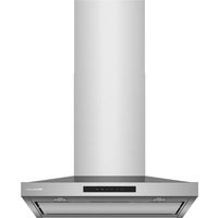
| Product Type | Range Hood |
| Brand | KitchenAid |
| Model | WVU31UC0FB |
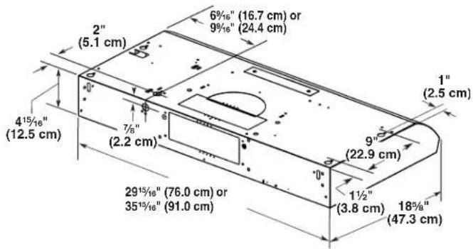
| Dimensions (W × D × H) | 76.0 × 47.3 × 16.7 cm (30" model) or 91.0 × 47.3 × 24.4 cm (36" model) |
| Power Supply | 120 V ~ 60 Hz, 15 A, protected circuit |
| Motor Power | 73 W (nominal) |
| Lighting | 1 E26 base bulb, 120 V, max 75 W |
| Fan Speed | Variable by rotary switch |
| Exhaust Type | External exhaust (7" round or 3 1/4" × 10" rectangular duct) or recirculation with optional charcoal filter |
| Material | Stainless steel |
| Grease Filter | Metal, dishwasher-safe or hand washable |
| Charcoal Filter | Optional, non-washable, lifespan approx. 6 months |
| Backdraft Damper | Rectangular 3 1/4" × 10" included |
| Maximum Duct Length | 10.7 m (rectangular) or 15.2 m (7" round) |
| Warranty | 1 year limited (parts and labor) |
Frequently Asked Questions - WVU31UC0FB KITCHENAID
User questions about WVU31UC0FB KITCHENAID
0 question about this device. Answer the ones you know or ask your own.
Ask a new question about this device
Download the instructions for your Range hood in PDF format for free! Find your manual WVU31UC0FB - KITCHENAID and take your electronic device back in hand. On this page are published all the documents necessary for the use of your device. WVU31UC0FB by KITCHENAID.
USER MANUAL WVU31UC0FB KITCHENAID
30" (76.2 CM) AND 36" (91.4 CM) RANGE HOOD
Installation Instructions and Use & Care Guide
For questions about features, operation/performance, parts, accessories or service, call: 1-800-253-1301 or visit our website at www.whirlpool.com
In Canada, call 1-800-807-6777 or visit our website at www.whirlpool.ca
HOTTE D'ASPIRATION DE 30" (76.2 CM) ET 36" (91.4 CM)
Models/Modèles:
WVU31UC0F/WVU31UC6F
RANGE HOOD SAFETY
Your safety and the safety of others are very important.
We have provided many important safety messages in this manual and on your appliance. Always read and obey all safety messages.

This is the safety alert symbol.
This symbol alerts you to potential hazards that can kill or hurt you and others.
All safety messages will follow the safety alert symbol and either the word "DANGER" or "WARNING."
These words mean:
DANGER
You can be killed or seriously injured if you don't immediately follow instructions.
WARNING
You can be killed or seriously injured if you don't follow instructions.
All safety messages will tell you what the potential hazard is, tell you how to reduce the chance of injury, and tell you what can happen if the instructions are not followed.
State of California Proposition 65 Warnings:
WARNING: This product contains one or more chemicals known to the State of California to cause cancer.
WARNING: This product contains one or more chemicals known to the State of California to cause birth defects or other reproductive harm.
IMPORTANT SAFETY INSTRUCTIONS
WARNING: TO REDUCE THE RISK OF FIRE, ELECTRIC SHOCK, OR INJURY TO PERSONS, OBSERVE THE FOLLOWING:
■ Use this unit only in the manner intended by the manufacturer. If you have questions, contact the manufacturer.
■ Before servicing or cleaning the unit, switch power off at service panel and lock the service disconnecting means to prevent power from being switched on accidentally. When the service disconnecting means cannot be locked, securely fasten a prominent warning device, such as a tag, to the service panel.
■ Installation work and electrical wiring must be done by qualified person(s) in accordance with all applicable codes and standards, including fire-rated construction.
■ Do not operate any fan with a damaged cord or plug. Discard fan or return to an authorized service facility for examination and/or repair.
■ Sufficient air is needed for proper combustion and exhausting of gases through the flue (chimney) of fuel burning equipment to prevent backdrafting. Follow the heating equipment manufacturer's guideline and safety standards such as those published by the National Fire Protection Association (NFPA), the American Society for Heating, Refrigeration and Air Conditioning Engineers (ASHRAE), and the local code authorities.
■ When cutting or drilling into wall or ceiling, do not damage electrical wiring and other hidden utilities.
■ Ducted fans must always be vented outdoors.
CAUTION: For general ventilating use only. Do not use to exhaust hazardous or explosive materials and vapors.
CAUTION: To reduce risk of fire and to properly exhaust air, be sure to duct air outside - do not vent exhaust air into spaces within walls or ceilings, attics or into crawl spaces, or garages.
WARNING: TO REDUCE THE RISK OF FIRE, USE ONLY METAL DUCTWORK.
WARNING: TO REDUCE THE RISK OF A RANGE TOP GREASE FIRE:
■ Never leave surface units unattended at high settings. Boilovers cause smoking and greasy spillovers that may ignite. Heat oils slowly on low or medium settings.
■ Always turn hood ON when cooking at high heat or when flambeing food (i.e. Crepes Suzette, Cherries Jubilee, Peppercorn Beef Flambé).
■ Clean ventilating fans frequently. Grease should not be allowed to accumulate on fan or filter.
■ Use proper pan size. Always use cookware appropriate for the size of the surface element.
WARNING: TO REDUCE THE RISK OF INJURY TO PERSONS IN THE EVENT OF A RANGE TOP GREASE FIRE, OBSERVE THE FOLLOWING: a
■ SMOTHER FLAMES with a close fitting lid, cookie sheet, or metal tray, then turn off the burner. BE CAREFUL TO PREVENT BURNS. If the flames do not go out immediately, EVACUATE AND CALL THE FIRE DEPARTMENT.
■ NEVER PICK UP A FLAMING PAN - you may be burned.
■ DO NOT USE WATER, including wet dishcloths or towels - a violent steam explosion will result.
■ Use an extinguisher ONLY if:
- You know you have a class ABC extinguisher, and you already know how to operate it.
- The fire is small and contained in the area where it started.
– The fire department is being called.
- You can fight the fire with your back to an exit.
a Based on "Kitchen Fire Safety Tips" published by NFPA.
■ WARNING: To reduce the risk of fire or electrical shock, do not use this fan with any solid-state speed control device.
READ AND SAVE THESE INSTRUCTIONS
TABLE OF CONTENTS TABLE DES MATIÈRES
RANGE HOOD SAFETY 2
INSTALLATION REQUIREMENTS....4
Tools and Parts....4
Location Requirements....4
Venting System 5
Electrical Requirements 6
INSTALLATION INSTRUCTIONS....7
RANGE HOOD USE....11
Range Hood Controls ....11
RANGE HOOD CARE....12
Cleaning 12
WIRING DIAGRAM....13
ASSISTANCE OR SERVICE....14
In the U.S.A. 14
In Canada....14
WARRANTY....15
SÉCURITÉ DE LA HOTTE DE CUISINIÈRE .....16
EXIGENCES D'INSTALLATION ....18
INSTRUCTIONS D'INSTALLATION....22
UTILISATION DE LA HOTTE ....26
ASSISTANCE OU SERVICE....29
Au Canada....29
GARANTIE....30
INSTALLATION REQUIREMENTS
Tools and Parts
Gather the required tools and parts before starting installation. Read and follow the instructions provided with any tools listed here.
Tools needed
| Metal snips |  | Wire stripper |  |
| #2 Phillips screwdriver |  | Flat-blade screwdriver |  |
| Pencil |  | Drill with 1/8"(3 mm), 1/2"(13 mm) and 11/4"(3 cm) bits |  |
| Caulking gun and weatherproof caulking compound |  |  | |
| Jigsaw or keyhole saw | |||
Parts supplied
Remove parts from package. Check that all parts are included.
#8-18 x 1"(4.2 x 25 mm)  flat-head screws flat-head screws | #8-18 x 5⁄8"(4.2 x 16 mm)  truss-head screws truss-head screws |
Drywall anchors  | Mounting brackets 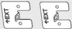 |
| Short Phillips head screws | |
31⁄4" x 10" (8.3 x 25.4 cm) rectangular damper 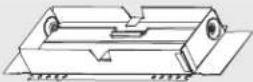 | |
Parts needed
| UL Listed/CSA Approved wire connectors |  | UL Listed/CSA Approved 1⁄2" (13 mm) strain relief | [XWAS] | 120V, 75W maximum, type E26 lamp | [822W] |
For 7" (17.8 cm) round vented installations
| 7" (17.8 cm)roundmetal ventsystem withwall or roof cap | 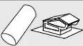 | 7" (17.8 cm)round damperPart NumberW10355451* |  |
| Vent clamps asrequired |  | 7" (17.8 cm)round ventmounting platePart NumberW10388168* |  |
For 31/4 " x 10" (8.3 x 25.4 cm) rectangular vented installations
| 31⁄4" x 10"(8.3 x 25.4 cm) rectangular metal vent system with wall or roof cap | 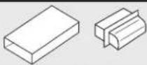 | Duct tape |
Optional accessories
| Charcoalfilter kitPart NumberW10355450* |  | Powercord kitPart NumberW10355452* |  | Stainless steelcleaner andpolishPart Number31462A* |
* For information on ordering, see the "Assistance or Service" section.
Location Requirements
IMPORTANT: Observe all governing codes and ordinances.
It is the installer's responsibility to comply with installation clearances specified on the model/serial/rating plate. The model/serial/rating plate is located inside the range hood on the left wall.
■Range hood location should be away from strong draft areas, such as windows, doors, and strong heating vents.
■Cabinet opening dimensions that are shown must be used. Given dimensions provide minimum clearance. Consult the cooktop/range manufacturer installation instructions before making any cutouts.
■This range hood is recommended for use with cooktops with a maximum total rating of 40,000 Btus or less.
■Grounded electrical outlet is required. See the "Electrical Requirements" section.
■All openings in ceiling and wall where range hood will be installed must be sealed.
■These range hoods are factory set for vented installations. Models that are capable of being installed as non-vented (recirculating) require charcoal filters. See the “Assistance or Service” section for information on ordering charcoal filters.
For Mobile Home Installations
The installation of this range hood must conform to the Manufactured Home Construction Safety Standards, Title 24 CFR, Part 328 (formerly the Federal Standard for Mobile Home Construction and Safety, title 24, HUD, Part 280) or when such standard is not applicable, the standard for Manufactured Home Installation 1982 (Manufactured Home Sites, Communities, and Setups) ANSI A225.1/NFPA 501A, or latest edition, or with local codes.
Product Dimensions
Installation Clearances
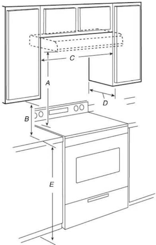
A. 24" (61 cm) minimum distance from electric cooking surface
24" (61 cm) minimum distance from gas cooking surface
30" (76.2 cm) suggested maximum above the cooking surface
B. 18" (45.7 cm) minimum clearance - upper cabinet to countertop
C. 30" (76.2 cm) minimum cabinet opening width for 30" (76.2 cm) model
36" (91.4 cm) minimum cabinet width for 36" (91.4 cm) models
D. 12" (30.5 cm) cabinet depth
E. 36" (91.4 cm) base cabinet height
Venting System
Venting Methods
NOTES:
■A flexible vent is not recommended. Flexible vent creates both back pressure and air turbulence that greatly reduce performance.
■The vent system is optional for this model.
Vent system can terminate either through the roof or wall. Use 31/4 x 10" (8.3 x 25.4 cm) rectangular with a maximum vent length of 35 ft (10.7 m) or 7" (17.8 cm) or larger round vent with a maximum length of 50 ft (15.2 m) for vent system.
Top Venting Wall Venting
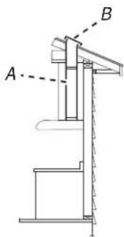
A. 7" (17.8 cm) round vent or 3 1/4 " x 10" (8.3 x 25.4 cm) rectangular vent through roof (purchased separately)
B. Roof cap with damper (purchased separately)
A. 7" (17.8 cm) round vent or 3' / 4" x 10" (8.3 x 25.4 cm) rectangular vent through wall (purchased separately)
B. Wall cap with damper (purchased separately)
Cold Weather Installations
An additional back draft damper should be installed to minimize backward cold air flow and a thermal break should be installed to minimize conduction of outside temperatures as part of the vent system. The damper should be on the cold air side of the thermal break.
The break should be as close as possible to where the vent system enters the heated portion of the house.
Makeup Air
Local building codes may require the use of makeup air systems when using ventilation systems greater than specified CFM of air movement. The specified CFM varies from locale to locale. Consult your HVAC professional for specific requirements in your area.
Venting Requirements
■Vent system must terminate to the outdoors, except for nonvented (recirculating) installations.
■Do not terminate the vent system in an attic or other enclosed area.
■Do not use a 4" (10.2 cm) laundry-type wall cap.
■Use 7" (17.8 cm) round metal vent or 3 1/4 " x 10" (8.3 x 25.4 cm) rectangular metal vent, depending on your installation requirement. Rigid metal vent is recommended. Plastic or metal foil vent is not recommended.
■The length of vent system and number of elbows should be kept to a minimum to provide efficient performance.
For the most efficient and quiet operation:
■Use no more than three 90° elbows.
■Make sure there is a minimum of 24" (61 cm) of straight vent between the elbows if more than 1 elbow is used.
■Do not install 2 elbows together.
■Use clamps or duct tape to seal all joints in the vent system.
■The vent system must have a damper. If roof or wall cap has a damper, do not use damper supplied with the range hood.
■Use caulking to seal exterior wall or roof opening around the cap.
Calculating Vent System Length
To calculate the length of the system you need, add the equivalent feet (meters) for each vent piece used in the system.
Vent System
| Vent Piece | |
| 45° elbow 2.5 ft (0.8 m) |  |
| 90° elbow 5 ft (1.5 m) | 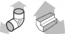 |
| 3 1/4 " x 10" (8.3 cm x 25.4 cm) flat elbow | 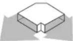 |
| 7" (17.8 cm) wall cap 0 ft (0 m) | 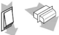 |
| 3 1/4 " x 10" (8.3 cm x 25.4 cm) to 7" (17.8 cm) |  |
| 3 1/4 " x 10" (8.3 cm x 25.4 cm) to 7" (17.8 cm) 90° elbow |  |
Example vent system
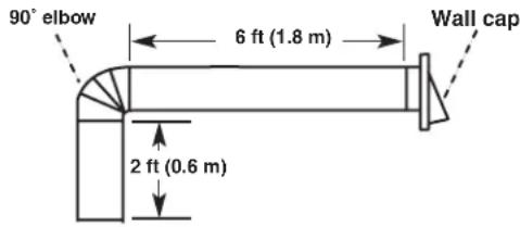
1 - 90° elbow = 5 ft (1.5 m)
1 - wall cap = 0 ft (0 m)
8 ft (2.4 m) straight = 8 ft (2.4 m)
System length = 13 ft (3.9 m)
Maximum Recommended Length
7" (17.8 cm) Round Vent = 50 ft (15.2 m)
31/4 x 10" (8.3 x 25.4 cm) = 35 ft (10.7 m)
Rectangular Vent
Electrical Requirements
Observe all governing codes and ordinances.
Ensure that the electrical installation is adequate and in conformance with National Electrical Code, ANSI/NFPA 70 (latest edition), or CSA Standards C22.1-94, Canadian Electrical Code, Part 1 and C22.2 No. 0-M91 (latest edition) and all local codes and ordinances.
If codes permit and a separate ground wire is used, it is recommended that a qualified electrician determine that the ground path is adequate.
A copy of the above code standards can be obtained from:
National Fire Protection Association
1 Batterymarch Park
Quincy, MA 02169-7471
CSA International
8501 East Pleasant Valley Road
Cleveland, OH 44131-5575
■A 120-volt, 60 Hz., AC-only, 15-amp, fused electrical circuit is required.
■If the house has aluminum wiring, follow the procedure below:
- Connect a section of solid copper wire to the pigtail leads.
- Connect the aluminum wiring to the added section of copper wire using special connectors and/or tools designed and UL Listed for joining copper to aluminum.
Follow the electrical connector manufacturer's recommended procedure. Aluminum/copper connection must conform with local codes and industry accepted wiring practices.
■Wire sizes and connections must conform with the rating of the appliance as specified on the model/serial/rating plate. The model/serial/rating plate is located inside the range hood on the left wall.
■Wire sizes must conform to the requirements of the National Electrical Code, ANSI/NFPA 70 (latest edition), or CSA Standards C22. 1-94, Canadian Electrical Code, Part 1 and C22.2 No. 0-M91 (latest edition) and all local codes and ordinances.
INSTALLATION INSTRUCTIONS
NOTES:
■Depending on your model, determine which venting method to use: roof, wall, or non-vented (recirculating).
It is recommended that the vent system be installed before the range hood is installed. Go to "Venting System" in the "Installation Requirements" section if you need assistance.
■Before making cutouts, make sure there is proper clearance within the ceiling or wall for the vent system.
1. Disconnect power
WARNING

Electrical Shock Hazard
Disconnect power before servicing.
Replace all parts and panels before operating.
Failure to do so can result in death or electrical shock.
2. Mark Hole Locations
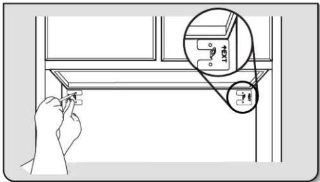
Align the exterior edge of the mounting brackets with the exterior edges of the upper cabinet.
IMPORTANT: The brackets should touch the upper cabinet. With a pencil, mark the upper holes on the brackets.
3. Install Brackets
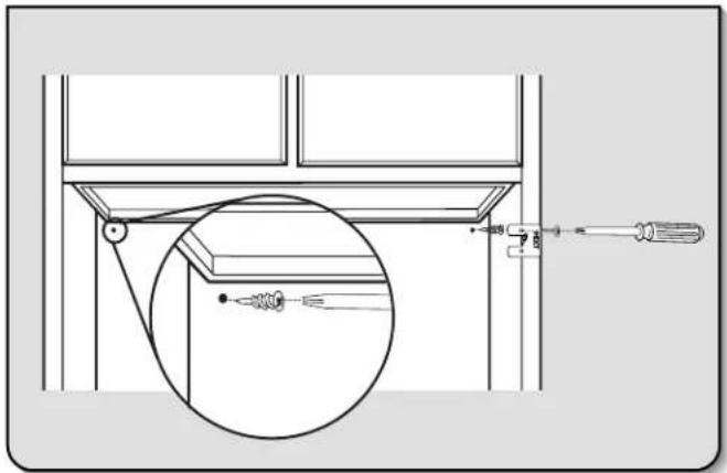
■Using a #2 Phillips screwdriver, install the drywall anchors.
■ Using #8-18 x 1" (4.2 x 25 mm) flat-head #2 Phillips screws, install the mounting brackets using the upper holes.
NOTE: For installations to a surface other than drywall, it is recommended that a qualified contractor determine the anchoring method.
4. Prepare Range Hood
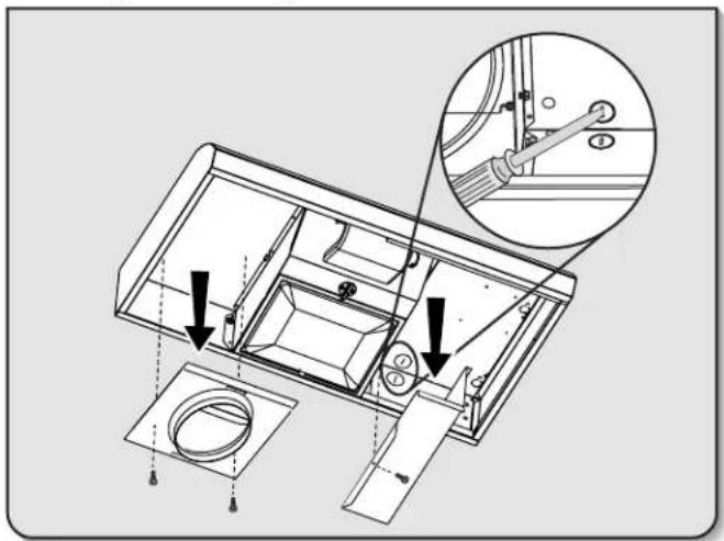
■Set the range hood on its back on a covered surface.
■Depending on your vent system, use a #2 Phillips screwdriver to remove the 7" (17.8 cm) round vent mounting plate or the rectangular damper attached with 3.5 x 9.5 mm screws.
■Using a #2 Phillips screwdriver, remove the electrical box cover.
■Using a flat-blade screwdriver, remove the appropriate power supply knockout.
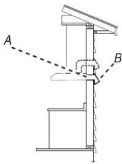
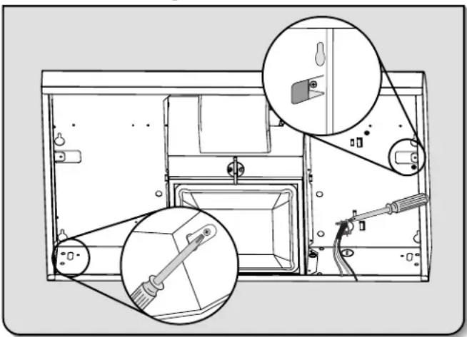
5. Mark Hole Locations
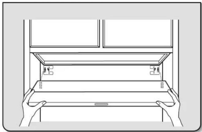
Lift the range hood into place and insert the mounting bracket tabs through the slots in the back of the range hood.
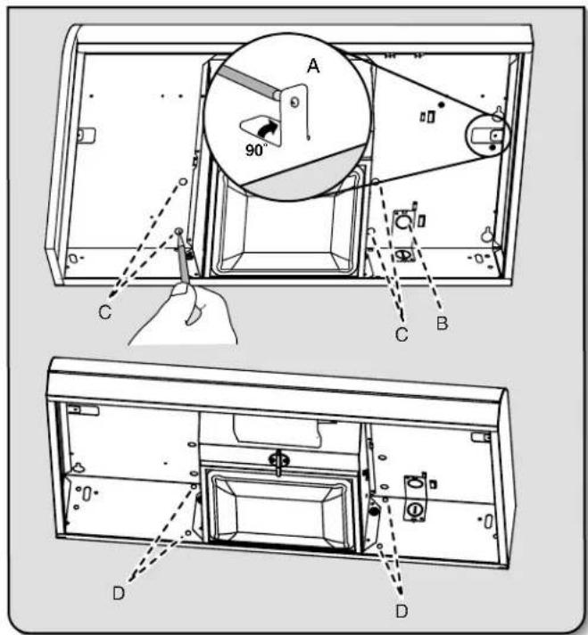
Hold the range hood firmly in place with one hand and bend each mounting tab (A) upward approximately 90°.
Mark the hole at the power supply knockout (B).
For a non-vented (recirculating) installation: Go to Step 7.
For a top-vented installation: Mark the 4 vent hole locations (C) on the top of the range hood.
For a rear-vented installation: Mark the 4 vent hole locations (D) on the rear of the range hood.
OPTIONAL: Mark the hole in each mounting tab.
Remove the range hood and set it aside.
6. Mark and Cut Vent Opening
3 1/4 " x 10" (8.3 x 25.4 cm) Rectangular Vent System
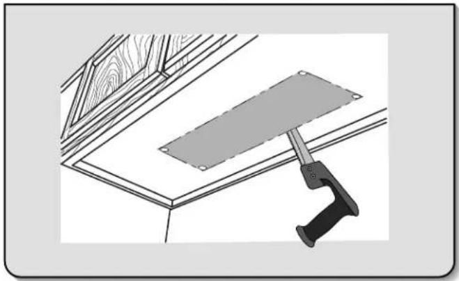
■Using a 1/2" (13 mm) drill bit, drill a hole in each of the dots marked previously on either the wall or upper cabinet. Using the outside edges of the holes, mark the vent opening.
■Using a jigsaw or keyhole saw, cut the vent opening.
7" (17.8 cm) Round Vent System
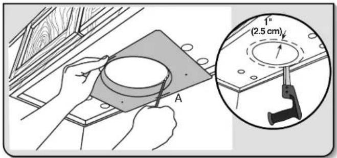
■Using the 7" (17.8 cm) round vent mounting plate, draw the vent opening outline on the underside of the cabinet:
-Place the vent mounting plate on the bottom of the cabinet. Position the edge of the plate with the widest distance (A) between the hole and edge of the mounting plate against the wall. Position the side edges of the mounting plate between the dots marked previously. IMPORTANT: The widest edge (A) of the vent mounting plate must be positioned against the wall.
-Trace the 7" (17.8 cm) vent opening (solid line) on the cabinet bottom.
■Using a jigsaw or keyhole saw, cut the vent opening 1" (2.5 cm) larger than the 7" (17.8 cm) hole traced (dashed line).
7. Drill Electrical Opening
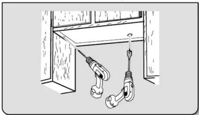
Using a 11/4 " (3 cm) drill bit, drill the hole in the dot marked previously at the electrical strain relief.
OPTIONAL: Using a 1/8 " (3 mm) drill bit, drill pilot holes for the dots marked previously at each mounting tab at an approximate 45° angle in an upward direction.
8. Prepare Range Hood Vents and Mounting Tabs
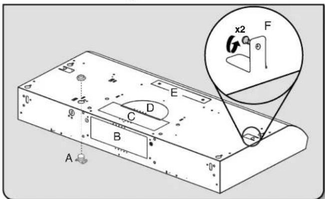
■Install Strain Relief
Install a UL Listed/CSA Approved 1/2 " (13 mm) strain relief (A).
■Mounting Tabs
Start a #8-18 x 5/8 " (4.2 x 16 mm) truss-head screw into the mounting tab (F) on each side of the range hood as shown in the inset. Insert the screws approximately 2 turns into the mounting tab holes.
■Non-vent (Recirculating) installations
Using a #2 Phillips screwdriver remove the 2 screws and remove the top, front rectangular vent cover (E). Go to Step 12.
■3 1/4" x 10" (8.3 x 25.4 cm) Rectangular Vent Installations
For top vent installations, remove the top, rectangular vent knockout (C).
OR
For wall vent installations, remove the rear rectangular vent knockout (B).
■7" (17.8 cm) Round Vent Installations
Remove both top knockouts (C and D).
9. Attach Vent Damper or Transition
3 1/4 " x 10" (8.3 x 25.4 cm) Rectangular Vent Damper
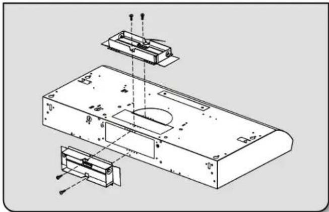
■Using (2) short Phillips head screws, install the 3 1/4 " x 10" (8.3 x 25.4 cm) rectangular damper over the top or rear vent knockout removed in Step 8.
NOTE: If the wall cap used has a damper and it interferes with the rectangular damper, remove the rectangular damper flap.
7" (17.8 cm) Round Vent Mounting Plate
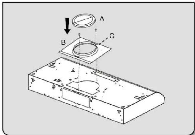
■ Using (2) short Phillips head screws, install the 7" (17.8 cm) round vent mounting plate over the vent knockouts removed in Step 8. Position the wide flange (C) to the front.
NOTE: An optional 7" (17.8 cm) round damper (A), Part Number W10355451, and a 7" (17.8 cm) round vent mounting plate (B), Part Number W10388168, are available as accessories. For information on ordering, see the "Assistance or Service" section.
■If installing the optional round damper, position it over the round vent mounting plate.
10. Mount Range Hood
■Lift the range hood into place, positioning the rear slots over the mounting brackets.
■Using a Phillips screwdriver, push on the screws that are started into the top mounting tabs and bend the tabs against the cabinet side walls. Attach the screws to the cabinet side walls.
IMPORTANT: Do not overtighten the screws.
■For direct wire installations, run the home power supply cable according to the National Electric Code or CSA standards and local codes and ordinances. There must be enough wiring from the fused disconnect (or circuit breaker) box to make the connection in the range hood electrical terminal box.
■Tighten the strain relief screws.
NOTE: Do not reconnect power until the installation is complete.
OPTIONAL: If you prefer, bend the rear tabs against the rear of the range hood and attach to the wall using #8-18 x 5/8" (4.2 x 16 mm) truss-head screws.
11. Connect Vent System
■Connect the ventwork to the range hood.
■Seal joints with vent clamps or duct tape to make secure and airtight.
■Check that the back draft dampers work properly.
12. Make Electrical Connection
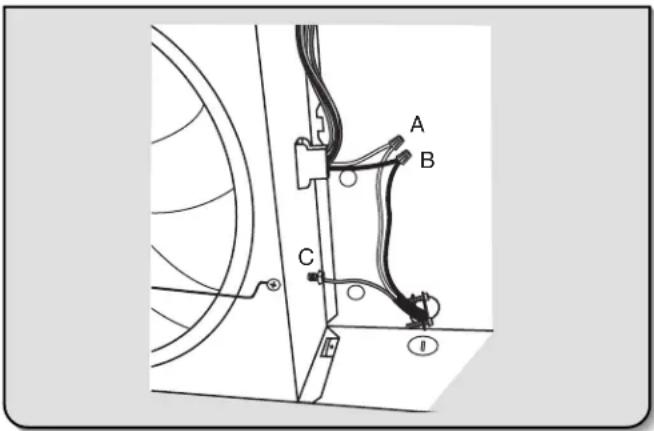
Option 1 - Direct Wire Installations
■Use a UL Listed/CSA Approved wire connector and connect the 2 white wires (A) together.
■Use a UL Listed/CSA Approved wire connector and connect the 2 black wires (B) together.
WARNING

Fire Hazard
Electrically ground the blower.
Use copper wire.
Connect ground wire to green ground screw in terminal box.
Failure to do so can result in death, fire, or electrical shock.
■Connect the green (or bare) ground wire (C) from the power supply to the green ground screw in the electrical box and tighten the screw securely.
Reinstall the electrical box cover. Reconnect power.
Option 2 - Power Cord Kit Installations
For optional power cord kit installations, follow the instructions supplied with the power cord kit. See the "Assistance or Service" section for information on ordering.
NOTE: Use only with range hood cord connection kits that have been investigated and found acceptable for use with this model range hood.
13. Complete the Installation
■Install a 120V, 75W maximum, light bulb with E26 base. See "Replacing the Light Bulb" in the "Range Hood Care" section.
■If removed previously, replace the filter. See “Metal or Charcoal Grease Filter” in the “Range Hood Care” section.
For vented installations: Install a metal filter.
For non-vented (recirculating) installations: Install a charcoal filter.
- Check the operation of the range hood fan and light. See the "Range Hood Use" section.
If the range hood does not operate, check to see whether a circuit breaker has tripped or a household fuse has blown. Disconnect the power and check the wiring connections.
NOTE: To get the most efficient use from your new range hood, read the "Range Hood Use" section.
RANGE HOOD USE
The range hood is designed to remove smoke, cooking vapors, and odors from the cooktop area. For best results, start the hood before cooking and allow it to operate several minutes after the cooking is complete to clear all smoke and odors from the kitchen.
The hood controls are located on the front panel of the range hood.
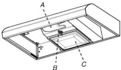
A. Light housing and cover
B. Grease filter retainer
C. Grease filter
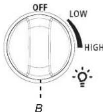
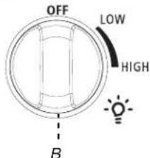
Range Hood Controls
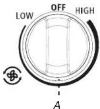
A. Fan speed switch
B. On/Off light switch
Operating the light
Turn the light switch to the right 1 position for Low (night light). Turn the light switch to the right 2 positions for High.
Operating the fan
The fan is variable speed. Rotate the fan switch to the right to turn the fan to the On position. Continue to rotate the switch to the desired fan speed.
To turn the fan off, rotate the fan speed switch to the left to the Off position.
RANGE HOOD CARE
Cleaning
IMPORTANT: Clean the hood and grease filters frequently according to the following instructions. Replace the grease filter before operating hood.
Exterior Surfaces
IMPORTANT: Do not use soap-filled scouring pads, abrasive cleaners, cooktop polishing creme, steel wool, gritty washcloths, or paper towels.
To avoid damage to the stainless steel, do not use cleaners that contain chlorine.
Cleaning Method:
■Liquid detergent or all-purpose cleaner:
Rinse with clean water and dry with a soft, lint-free cloth.
■Glass cleaner to remove fingerprints.
■For stainless steel models rub in the direction of the grain to avoid scratching, or damaging the surface.
■For stainless steel models, use Stainless Steel Cleaner and Polish, Part Number 31462A (not included): See the "Assistance or Service" section to order.

Metal or Charcoal Grease Filter
To Clean the Filter:
- Remove the screw from the grease filter retainer.
- Turn the grease filter retainer to release the filter.
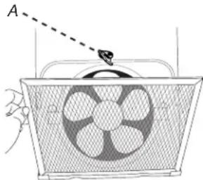
A. Filter retainer
- For vented installations: Wash the metal filter as needed in a dishwasher or hot detergent solution.
For non-vented (recirculating) installations: Replace the metal filter with a charcoal filter. The charcoal filter is not washable. It should last up to 6 months with normal use. For information on ordering, see the "Assistance or Service" section. Dispose of old charcoal filter.
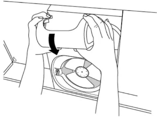
To Replace the Filter:
- To reinstall the filter, place the back edge of the filter into the channel at the rear of the hood. Push the filter into place and turn the filter retainer to secure the filter to the range hood.
- Replace the screw in the grease filter retainer.
Replacing the Light Bulb
Turn off the range hood and allow the light bulb to cool.
- Disconnect power.
- Squeeze the plastic lens cover and remove it from the hood.
- Screw a 120V, 75W maximum, light bulb with E26 base into the socket.
- Replace the lens cover by squeezing the cover and inserting the tabs into the slots.
- Reconnect power.
If the new light does not operate, make sure the light bulb is inserted correctly before calling service.
WIRING DIAGRAM

ASSISTANCE OR SERVICE
If you need service
Please refer to the warranty page in this manual.
If you need replacement parts
If you need to order replacement parts, we recommend that you use only factory specified parts. Factory specified parts will fit right and work right because they are made with the same precision used to build every new appliance.
To locate factory specified replacement parts in your area, call the following customer assistance telephone number or your nearest designated service center.
In the U.S.A.
Call the Whirlpool Customer eXperience Center toll-free:
1-800-253-1301 or visit our website at www.whirlpool.com.
Our consultants provide assistance with:
■Scheduling of service. Whirlpool designated service technicians are trained to fulfill the product warranty and provide after-warranty service anywhere in the United States.
■Features and specifications on our full line of appliances.
■Referrals to local dealers.
■Installation information.
■Use and maintenance procedures.
■Accessory and repair parts sales.
■Specialized customer assistance (Spanish speaking, hearing impaired, limited vision, etc.).
For further assistance
If you need further assistance, you can write to Whirlpool
Corporation with any questions or concerns at:
Whirlpool Brand Home Appliances
Customer eXperience Center
553 Benson Road
Benton Harbor, MI 49022-2692
Please include a daytime phone number in your correspondence.
In Canada
Call the Whirlpool Canada LP Customer eXperience
Centre toll-free: 1-800-807-6777 or visit our webpage www.whirlpool.ca.
Our consultants provide assistance with:
■Scheduling of service. Whirlpool designated service technicians are trained to fulfill the product warranty and provide after-warranty service anywhere in Canada.
■Features and specifications on our full line of appliances.
■Referrals to local Whirlpool dealers.
■Use and maintenance procedures.
■Accessory and repair parts sales.
■Referrals to local dealers, repair parts distributors, and service companies. Whirlpool Canada LP designated service technicians are trained to fulfill the product warranty and provide after-warranty service anywhere in Canada.
For further assistance
If you need further assistance, you can write to Whirlpool
Canada LP with any questions or concerns at:
Whirlpool Brand Home Appliances
Customer eXperience Centre
Whirlpool Canada LP
200 - 6750 Century Ave.
Mississauga, Ontario L5N 0B7
Please include a daytime phone number in your correspondence.
WHIRLPOOL® MAJOR APPLIANCE LIMITED WARRANTY
ATTACH YOUR RECEIPT HERE. PROOF OF PURCHASE IS REQUIRED TO OBTAIN WARRANTY SERVICE.
Please have the following information available when you call the Customer eXperience Center:
■Name, address and telephone number
■Model number and serial number
■A clear, detailed description of the problem
■ Proof of purchase including dealer or retailer name and address
IF YOU NEED SERVICE:
- Before contacting us to arrange service, please determine whether your product requires repair. Some questions can be addressed without service. Please take a few minutes to review the Troubleshooting or Problem Solver section of the Use and Care Guide, scan the QR code on the right to access additional resources, or visit www.whirlpool.com/product_help.
- All warranty service is provided exclusively by our authorized Whirlpool Service Providers. In the U.S. and Canada, direct all requests for warranty service to:
Whirlpool Customer eXperience Center

www.whirlpool.com/product_help
In the U.S.A., call 1-800-253-1301. In Canada, call 1-800-807-6777.
If outside the 50 United States or Canada, contact your authorized Whirlpool dealer to determine whether another warranty applies.
ONE YEAR LIMITED WARRANTY
WHAT IS COVERED WHAT IS NOT COVERED
For one year from the date of purchase, when this major appliance is installed, operated and maintained according to instructions attached to or furnished with the product, Whirlpool Corporation or Whirlpool Canada LP (hereafter "Whirlpool") will pay for Factory Specified Replacement Parts and repair labor to correct defects in materials or workmanship that existed when this major appliance was purchased, or at its sole discretion replace the product. In the event of product replacement, your appliance will be warranted for the remaining term of the original unit's warranty period.
YOUR SOLE AND EXCLUSIVE REMEDY UNDER THIS LIMITED WARRANTY SHALL BE PRODUCT REPAIR AS PROVIDED HEREIN. Service must be provided by a Whirlpool designated service company. This limited warranty is valid only in the United States or Canada and applies only when the major appliance is used in the country in which it was purchased. This limited warranty is effective from the date of original consumer purchase. Proof of original purchase date is required to obtain service under this limited warranty.
- Commercial, non-residential, multiple-family use, or use inconsistent with published user, operator or installation instructions.
- In-home instruction on how to use your product.
- Service to correct improper product maintenance or installation, installation not in accordance with electrical or plumbing codes or correction of household electrical or plumbing (i.e. house wiring, fuses or water inlet hoses).
- Consumable parts (i.e. light bulbs, batteries, air or water filters, preservation solutions, etc.).
- Defects or damage caused by the use of non-genuine Whirlpool parts or accessories.
- Conversion of products from natural gas or L.P. gas.
- Damage from accident, misuse, abuse, fire, floods, acts of God or use with products not approved by Whirlpool.
- Repairs to parts or systems to correct product damage or defects caused by unauthorized service, alteration or modification of the appliance.
- Cosmetic damage including scratches, dents, chips, and other damage to the appliance finishes unless such damage results from defects in materials and workmanship and is reported to Whirlpool within 30 days.
-
Discoloration, rust or oxidation of surfaces resulting from caustic or corrosive environments including but not limited to high salt concentrations, high moisture or humidity or exposure to chemicals.
-
Food or medicine loss due to product failure.
-
Pick-up or delivery. This product is intended for in-home repair.
-
Travel or transportation expenses for service in remote locations where an authorized Whirlpool servicer is not available.
-
Removal or reinstallation of inaccessible appliances or built-in fixtures (i.e. trim, decorative panels, flooring, cabinetry, islands, countertops, drywall, etc.) that interfere with servicing, removal or replacement of the product.
-
Service or parts for appliances with original model/serial numbers removed, altered or not easily determined.
The cost of repair or replacement under these excluded circumstances shall be borne by the customer.
DISCLAIMER OF IMPLIED WARRANTIES
IMPLIED WARRANTIES, INCLUDING ANY IMPLIED WARRANTY OF MERCHANTABILITY OR IMPLIED WARRANTY OF FITNESS FOR A PARTICULAR PURPOSE, ARE LIMITED TO ONE YEAR OR THE SHORTEST PERIOD ALLOWED BY LAW. Some states and provinces do not allow limitations on the duration of implied warranties of merchantability or fitness, so this limitation may not apply to you. This warranty gives you specific legal rights, and you also may have other rights that vary from state to state or province to province.
DISCLAIMER OF REPRESENTATIONS OUTSIDE OF WARRANTY
Whirlpool makes no representations about the quality, durability, or need for service or repair of this major appliance other than the representations contained in this warranty. If you want a longer or more comprehensive warranty than the limited warranty that comes with this major appliance, you should ask Whirlpool or your retailer about buying an extended warranty.
LIMITATION OF REMEDIES; EXCLUSION OF INCIDENTAL AND CONSEQUENTIAL DAMAGES
YOUR SOLE AND EXCLUSIVE REMEDY UNDER THIS LIMITED WARRANTY SHALL BE PRODUCT REPAIR AS PROVIDED HEREIN. WHIRLPOOL SHALL NOT BE LIABLE FOR INCIDENTAL OR CONSEQUENTIAL DAMAGES. Some states and provinces do not allow the exclusion or limitation of incidental or consequential damages, so these limitations and exclusions may not apply to you. This warranty gives you specific legal rights, and you also may have other rights that vary from state to state or province to province.
SÉCURITÉ DE LA HOTTE DE CUISINIÈRE
National Fire Protection Association
1 Batterymarch Park
Quincy, MA 02169-7471
CSA International
8501 East Pleasant Valley Road
Cleveland, OH 44131-5575
ASSISTANCE OU SERVICE

- 30" (76.2 CM) AND 36" (91.4 CM) RANGE HOOD
- HOTTE D'ASPIRATION DE 30" (76.2 CM) ET 36" (91.4 CM)
- RANGE HOOD SAFETY
- YOUR SAFETY AND THE SAFETY OF OTHERS ARE VERY IMPORTANT
- DANGER
- WARNING
- IMPORTANT SAFETY INSTRUCTIONS
- READ AND SAVE THESE INSTRUCTIONS
- TABLE OF CONTENTS TABLE DES MATIÈRES
- INSTALLATION REQUIREMENTS
- TOOLS AND PARTS
- PARTS SUPPLIED
- LOCATION REQUIREMENTS
- FOR MOBILE HOME INSTALLATIONS
- VENTING SYSTEM
- VENTING METHODS
- NOTES
- COLD WEATHER INSTALLATIONS
- MAKEUP AIR
- VENTING REQUIREMENTS
- FOR THE MOST EFFICIENT AND QUIET OPERATION
- CALCULATING VENT SYSTEM LENGTH
- MAXIMUM RECOMMENDED LENGTH
- ELECTRICAL REQUIREMENTS
- INSTALLATION INSTRUCTIONS
- DISCONNECT POWER
- ELECTRICAL SHOCK HAZARD
- MARK HOLE LOCATIONS
- INSTALL BRACKETS
- PREPARE RANGE HOOD
- MARK AND CUT VENT OPENING
- DRILL ELECTRICAL OPENING
- PREPARE RANGE HOOD VENTS AND MOUNTING TABS
- INSTALL STRAIN RELIEF
- MOUNTING TABS
- NON-VENT (RECIRCULATING) INSTALLATIONS
- 3 1/4" X 10" (8.3 X 25.4 CM) RECTANGULAR VENT INSTALLATIONS
- OR
- 7" (17.8 CM) ROUND VENT INSTALLATIONS
- ATTACH VENT DAMPER OR TRANSITION
- MOUNT RANGE HOOD
- CONNECT VENT SYSTEM
- MAKE ELECTRICAL CONNECTION
- OPTION 1 - DIRECT WIRE INSTALLATIONS
- OPTION 2 - POWER CORD KIT INSTALLATIONS
- COMPLETE THE INSTALLATION
- RANGE HOOD USE
- OPERATING THE LIGHT
- OPERATING THE FAN
- RANGE HOOD CARE
- CLEANING
- EXTERIOR SURFACES
- CLEANING METHOD
- METAL OR CHARCOAL GREASE FILTER
- TO CLEAN THE FILTER
- TO REPLACE THE FILTER
- REPLACING THE LIGHT BULB
- ASSISTANCE OR SERVICE
- IF YOU NEED SERVICE
- IF YOU NEED REPLACEMENT PARTS
- IN THE U.S.A
- OUR CONSULTANTS PROVIDE ASSISTANCE WITH
- FOR FURTHER ASSISTANCE
- IN CANADA
- WHIRLPOOL® MAJOR APPLIANCE LIMITED WARRANTY
- ONE YEAR LIMITED WARRANTY
- WHAT IS COVERED WHAT IS NOT COVERED
- DISCLAIMER OF IMPLIED WARRANTIES
- DISCLAIMER OF REPRESENTATIONS OUTSIDE OF WARRANTY
- LIMITATION OF REMEDIES; EXCLUSION OF INCIDENTAL AND CONSEQUENTIAL DAMAGES
- SÉCURITÉ DE LA HOTTE DE CUISINIÈRE
- ASSISTANCE OU SERVICE
Brand : KITCHENAID
Model : WVU31UC0FB
Category : Range hood