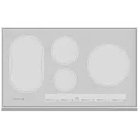
KIC36MS - Cooker Hestan - Free user manual and instructions
Find the device manual for free KIC36MS Hestan in PDF.


| Product Type | Induction Cooktop |
| Brand | Hestan |
| Model | KIC36MS |
| Width | 36 inches (91.4 cm) |
| Minimum depth of unprotected cabinets | 13 inches (33 cm) |
| Minimum height from countertop to cabinet | 18 inches (45.7 cm) |
| Power supply | 240 V / 208 V, 60 Hz, single phase |
| Total power | 10.8 kW (240 V) / 9.4 kW (208 V) |
| Maximum current | 45 A |
| Recommended circuit protection | 50 A (circuit breaker or fuse) |
| Cooking type | Induction |
| Number of cooking zones | 4 (estimate, not explicitly specified for this model but typical for 36 inches) |
| Functions | Touch control, lock (LOCK), pause, Power Booster, accidental shutdown |
| Safety | Child lock, mandatory grounding, automatic shut-off |
| Table material | Glass (mentioned in the manual) |
| Maintenance | Clean with a soft cloth, avoid abrasive products |
| Installation | Built-in, requires cutout in countertop |
| Compliance | UL STD 858, CSA C22.2 No.61, FCC |
| Intended use | Household only (not for mobile homes or outdoors) |
| Spare parts | Available at hestanhome.com |
| After-sales service | Contact Hestan at (888) 905-7463 or local dealer |
Frequently Asked Questions - KIC36MS Hestan
User questions about KIC36MS Hestan
0 question about this device. Answer the ones you know or ask your own.
Ask a new question about this device
Download the instructions for your Cooker in PDF format for free! Find your manual KIC36MS - Hestan and take your electronic device back in hand. On this page are published all the documents necessary for the use of your device. KIC36MS by Hestan.
USER MANUAL KIC36MS Hestan
natural_image
Close-up of a plated dish featuring sliced meat, cherry tomatoes, and garnished with green herbs (no text or symbols visible)INDOOR COOKING
Induction Cooktop KIC
Installation Manual
WARNING
IF THE INFORMATION IN THIS MANUAL IS NOT FOLLOWED EXACTLY, A FIRE OR EXPLOSION MAY RESULT CAUSING PROPERTY DAMAGE, PERSONAL INJURY, OR DEATH.
Do not store or use gasoline or other flammable vapors and liquids in the vicinity of this or any other appliance.
Installation and service must be performed by a qualified installer or service agency.
DO NOT REPAIR, REPLACE OR REMOVE ANY PART OF THE APPLIANCE UNLESS SPECIFICALLY RECOMMENDED IN THE MANUAL. IMPROPER INSTALLATION, SERVICE OR MAINTENANCE CAN CAUSE INJURY OR PROPERTY DAMAGE. REFER TO THIS MANUAL FOR GUIDANCE. ALL OTHER SERVICING SHOULD BE DONE BY A QUALIFIED TECHNICIAN.
READ THESE INSTRUCTIONS CAREFULLY AND COMPLETELY BEFORE INSTALLING OR USING YOUR APPLIANCE TO REDUCE THE RISK OF FIRE, BURN HAZARD, OR OTHER INJURY. KEEP THIS MANUAL FOR FUTURE REFERENCE.
SAFETY DEFINITIONS
WARNING
THIS INDICATES THAT DEATH OR SERIOUS INJURY MAY OCCUR AS A RESULT OF NOT OBSERVING THIS WARNING
CAUTION
THIS INDICATES THAT MINOR OR MODERATE INJURY MAY OCCUR AS A RESULT OF NOT OBSERVING THIS WARNING.
NOTICE
THIS INDICATES THAT DAMAGE TO THE APPLIANCE OR PROPERTY MAY OCCUR AS A RESULT OF NOT OBSERVING THIS WARNING.
INSTALLER: LEAVE THIS MANUAL WITH THE OWNER OF THE APPLIANCE. HOMEOWNER: RETAIN THIS MANUAL FOR FUTURE REFERENCE.
1 SAFETY PRECAUTIONS - BEFORE YOU BEGIN
2 MODEL NUMBERS
2 RATING LABEL
2 REGULATORY / CODE REQUIREMENTS
3 CUTOUT DIMENSIONS AND REQUIREMENTS
6 COOKTOP INSTALLATION
10 ELECTRICAL CONNECTIONS
12 FINAL SETUP
13 PARTS LIST
13 SERVICE
SAFETY PRECAUTIONS - BEFORE YOU BEGIN
When properly cared for, your Hestan appliance will provide safe, reliable service for many years. When using this appliance, basic safety practices must be followed as outlined below.
IMPORTANT: Save these instructions for the local Utility Inspector's use.
INSTALLER: Please leave these Installation Instructions with the owner.
OWNER: Please retain these Installation Instructions for future reference.
This appliance is NOT designed for installation in manufactured (mobile) homes or recreational park trailers. Do NOT install this appliance outdoors.
WARNING
ELECTRICAL SHOCK HAZARD
Disconnect power before installing or servicing appliance. Failure to do so can result in death or electrical shock.

natural_image
Silhouette of a person in motion with a curved arrow, no text or symbols presentELECTRICAL GROUNDING
- This appliance must be grounded. Grounding reduces the risk of electric shock in the event of a short circuit. Read the ELECTRICAL CONNECTIONS section of this manual for complete instructions.
• DO NOT ground to a gas pipe. - DO NOT use an extension cord with this appliance.
- DO NOT have a fuse in the NEUTRAL or GROUNDING circuit. A fuse in the NEUTRAL or GROUNDING circuit could result in an electrical shock.
OVEN MODELS
| MODEL NO. DESCRIPTION | CIRCUIT BREAKERREQ'D |
| KIC 30 30" Induction Cooktop 40 Amp | |
| KIC 36 36" Induction Cooktop 50 Amp |
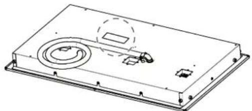
RATING LABEL
The rating label contains important information about your Hestan appliance such as the model and serial number, electrical rating and the minimum installation clearances.
The rating label is located on the bottom of the cooktop.
If service is necessary, contact Hestan Customer Care with the model and serial number information shown on the label.

TYPICAL RATING LABEL
natural_image
Technical line drawing of a rectangular electronic device with internal components and mounting holes (no text or symbols)Location of rating label
REGULATORY / CODE REQUIREMENTS
Installation of this cooking appliance must be made in accordance with local codes. In the absence of local codes, this unit should be installed in accordance with the National Electrical Code and local codes.
This appliance must be electrically grounded in accordance with local codes or in the absence of local codes with the National Electrical Code ANSI/NFPA 70, or Canadian Electrical code CSA C22.1.
30"
![30" 3/8 [771 mm] 21" 3/16 [538 mm] 1/4" [6mm] 2" 5/8 [66 mm] 1" 1/16 [27 mm]](/content/2026/04/608019/images/288d3a483fbd30e757c58c8c7ff03d5a8700323fd7f4bcc0984b02ca171d8d9f.jpg)
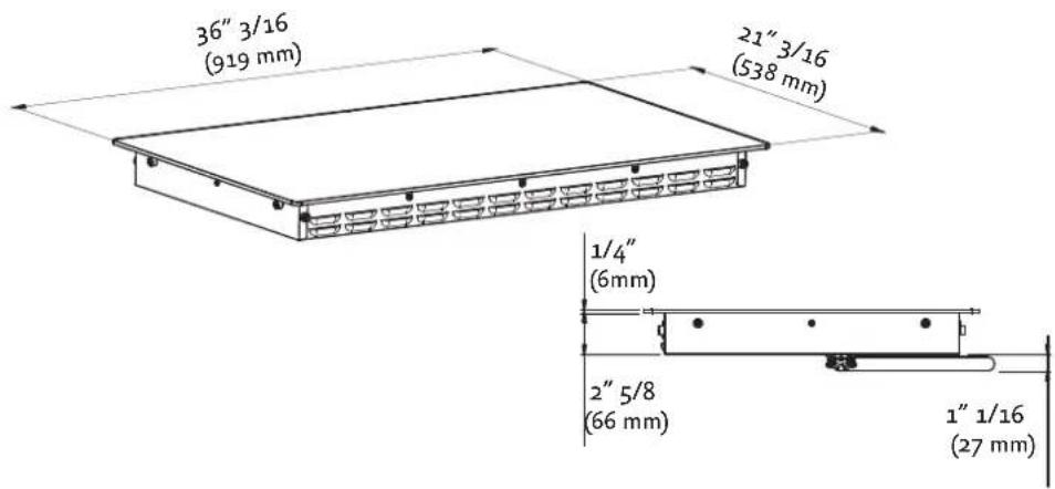
36"
![36" 3/16 [919 mm] 21" 3/16 [538 mm] 1/4" [6mm] 2" 5/8 [66 mm] 1" 1/16 [27 mm]](/content/2026/04/608019/images/019af61780eac099a008f03022fbd2aa044d55c0d14aaaa2419e12ae345f7960.jpg)
CUTOUT DIMENSION
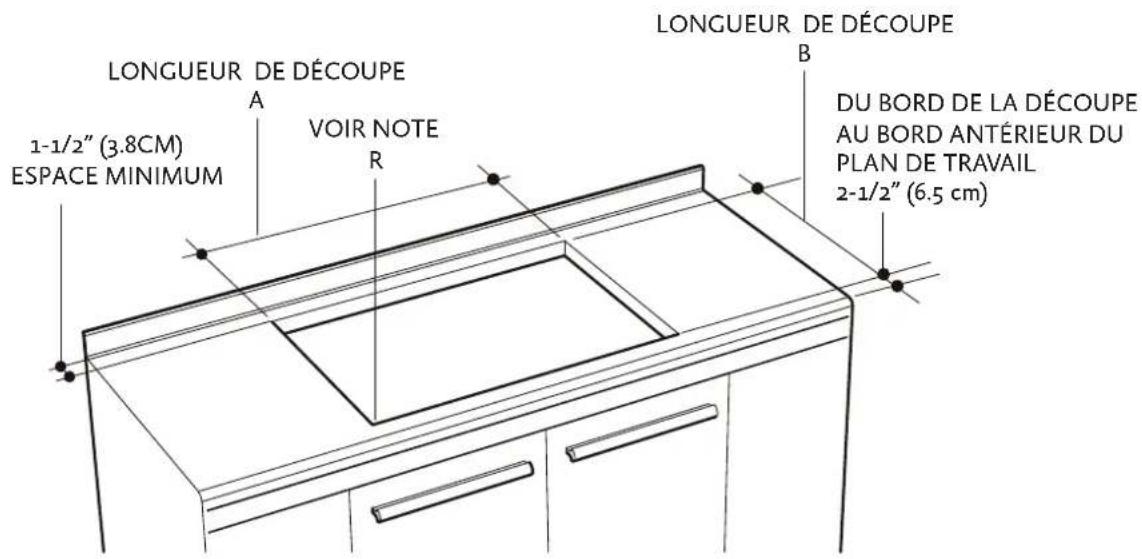
![LENGTH OF CUT 1-1/2" [3.8cm] MIN CLEARANCE A SEE NOTE R LENGTH OF CUT FROM EDGE OF CUTOUT TO FRONT EDGE OF COUNTERTOP 2-1/2" [6.5 cm]](/content/2026/04/608019/images/214ca989de8ff71a3726d97a2d50599da2ef4e1ee64cfa783e216f388dbdbb5a.jpg)
CUTOUT REQUIREMENTS

WALL COVERING CABINETS, AND COUNTERTOP MUST WITHSTAND HEAT UP TO 200° F [93° C]
| Cutout width | A | B | C |
| 30”[76.2cm] | 28-3/4” +/- 1/16”[73.0 cm +/- 0.1cm] | 19-7/16” +/- 1/16”[49.4 cm +/- 1mm] | 30”[76.2 cm] min |
| 36”[91.4cm] | 34-5/8” +/- 1/16”[87.9 cm +/- 0.1cm] | 19-7/16” +/- 1/16”[49.4 cm +/- 1mm] | 36”[91.4 cm] min |
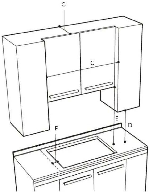
| Cutout width | D | E | F | G |
| 30”[76.2cm] | 18” [45.7 cm] minHeight from counter-top to nearest cabinet on either side of unit | 30” [76.2 cm] min.[see note*] Clearance from countertop to unprotected overhead surface | 2” [5 cm] min Clearance from cutout to side wall on the left and right of the unit | 13” [33 cm] Depth of unprotected overhead cabinets |
| 36”[91.4cm] |
NOTICE
Under the cooktop it is necessary to install a partition, as shown.
NOTE: 24" [61 cm] min. clearance if bottom of wood or metal cabinets is protected by not less than 1/4" [0.6 cm] flame retardant millboard covered with no less than No. 28 MSG sheet steel 0.015" [0.04 cm] stainless steel, or 0.024" [0.06 cm] aluminum or 0.020" [0.05 cm] copper. 30" [76.2 cm] min. clearance between top of cooking platform and bottom of unprotected wood or metal cabinet.
Important Preparation Suggestions
- Chamfer all exposed edges of decorative laminate to prevent damage from chipping.
- Radius corners of cutout and file to ensure smooth edges and prevent corner cracking. Recommend 1/4" or 3/8" diameter drill to start cut at each corner.
- Rough edges, inside corners which have not been rounded and forced fits can contribute to cracking of the countertop laminate.
VERTICAL CLEARANCES
* The ventilation opening is to extend the full length of the cooktop cutout.
![*1/4" [6 mm] min 25" [635 mm] min 2 1/2" [64mm] 3" [76 mm] 19 7/16"[494 mm] 1 5/8" [40 mm] max 5" [127 mm] min 2 1/2" [65 mm] 15 3/4" [400 mm] 36" [915 mm] 24" [610 mm] min 4 3/4" [120 mm] 1 1/2" [38 mm] min Partitian](/content/2026/04/608019/images/8dd489934d958c9c63d2be4e7564cf3560ee5d77092e622a145ce1c7a9733d29.jpg)
CAUTION
EXCESSIVE WEIGHT HAZARD
Use two or more people to move and install cooktop. Failure to do so can result in back or other injury.
CUT HAZARD
Beware of sharp edges. Use the polystyrene ends when carrying the product. Failure to use caution could result in minor injury or cuts.
Always consult the countertop manufacturer for specific instructions.
- Ensure the countertop is square and level and ensure no structural members interfere with space requirements.
• Prepare the cut-out according to the instructions (see cut-out dimensions). - Make sure the wall coverings, countertop and cabinets around the cooktop can withstand heat (up to 200°F / 93°C).
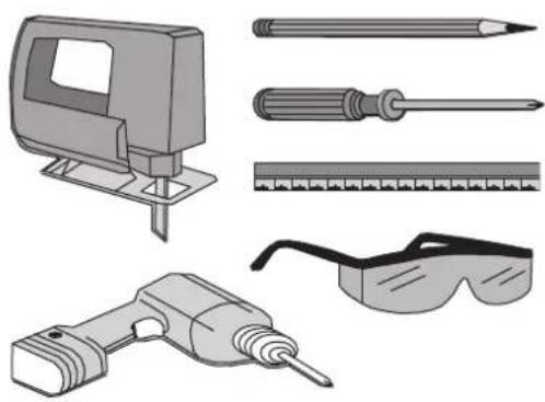
TOOLS WILL YOU NEED
natural_image
Illustration of various electrical components including a power shaver, screwdriver, and eyeglasses (no text or symbols present)STEP 1
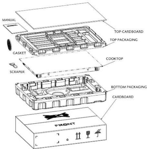
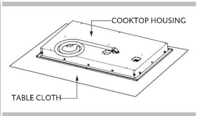
Remove packaging materials and literature package from the cooktop before beginning installation. Remove Installation Manual from literature pack and read them carefully before you begin.
PARTS
STEP 3
A foam tape is provided to seal the cooktop edges to the countertop. Apply tape approximately 1/16" (1.5 mm) from the glass edge to the underside of the cooktop glass. Use tape around the entire glass perimeter. Cut off excess where tape ends butt.

STEP 4
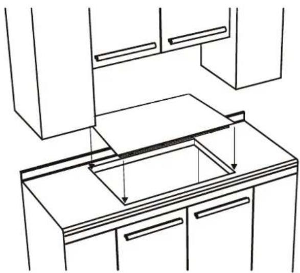
Insert the cooktop centered into the cutout opening. Make sure the front edge of the counter top is parallel to the cooktop.
Make a final check that all required clearances are met.
natural_image
Line drawing of a kitchen counter with drawers and appliances (no text or symbols)STEP 5
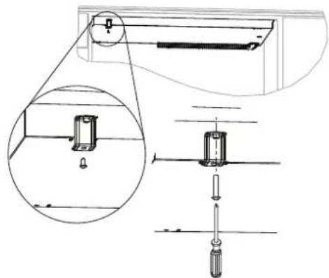
Four or six clamp brackets are provided to clamp the cooktop to the countertop. Tighten screws just enough to hold brackets in place when cooktop is put into cutout.
When all brackets are in place, tighten screws securely.
natural_image
Technical diagram showing a mechanical assembly with a magnified inset of a component detail (no text or symbols present)NOTICE
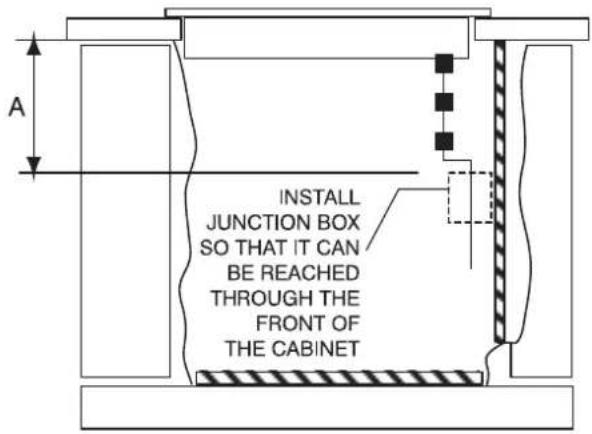
• THE ELECTRICAL CONDUIT IS 3 FEET LONG.
- The junction box must be located where it will allow considerable slack in the conduit for serviceability.
NOTICE
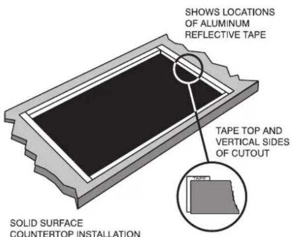
- For solid surface material installations such as Surel™ and Corian®, consult with solid surface manufacturer. Apply heat reflective tape such as Scotch® Aluminum Foil Tape #425 or #427 around the cutout so that it folds over on the top and sides.
- Do not wrap the tape underneath the cooktop.
- Be sure the tape extends beyond the outermost flange of the cooktop. All corners should be covered with tape.
ELECTRIC OPENING
A: 12" (30.5 cm) MIN FROM BOTTOM OF COUNTERTOP AND ADJACENT CABINET (RIGHT SIDE)
NOTICE
Use the countertop opening dimensions that are given with these Instructions.
- Check the cooktop base for an approved installation label. Verify approved oven model numbers that can be installed with your cooktop model number.
• The cooktop may be installed over a single oven.
• The cooktop should be centered over the oven. - Both the cooktop and the oven must be installed according to each specific installation instruction.
* The ventilation opening is to extend the full length of the cooktop cutout.
![*1/4" [6 mm] min 1/4" [6mm] min 2 1/2" [64mm] 25" [635 mm] min 3" [76 mm] 19 7/16" [494 mm] 1 5/8" [40 mm] max 2 1/2" [65 mm] 27 1/4" [692 mm] 4 3/4" [120 mm] 1 1/2" [38 mm] min 36" [915 mm] 24" [610mm] min 4" [101mm] min](/content/2026/04/608019/images/69af1dec498df97565325e852c676454e40d0a936c710bf8884952f482f3ab92.jpg)
WARNING
Disconnect power before servicing the product. Failure to do so could result in death or electrical shock.
General information
NOTICE
The models may be powered at 240V or 208V.
This cooktop does not require a neutral connection. If the cooktop is to be completely enclosed in a cabinet, feed the cooktop cable through the opening in the cabinet. Make the electrical connection following the appropriate steps for your installation. Your cooktop must be connected to the proper electrical voltage and frequency as specified in the table on the right.
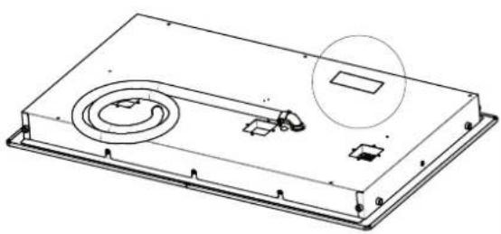
Location of serial tag
natural_image
Technical line drawing of a device casing with a circular component and mounting bracket (no text or symbols)The flexible conduit (supplied) 3 feet long (100 cm) located at the right rear of the cooktop bottom box should be connected directly into a junction box. Do not cut the conduit. A U.L - or CSA - listed conduit connector must be provided at each end of the power supply cable (at the cooktop and at the junction box.) A time delay fuse or circuit breaker is recommended. Do not ground to a gas pipe. Do not have a fuse in the grounding or neutral circuit. Fuse both supply (phase) lines.
NOTICE
Improper connection of aluminum house wiring to the copper leads can result in a serious problem such as an electrical fire.
| Model | Power Supply | ||||
| 240 V 60 Hz | 208 V 60 Hz | Approval code | |||
| 30" KIC30 | 7.2 kW | 30A | 6.45 kW | 31A | 815T40*T |
| 36" KIC36 | 10.8 kW | 45A | 9.4 kW | 45A | 815V50*U |
National Fire Protection Association Batterymarch Park, Quincy, Massachusetts 02169-7471
A three-wire, single phase, 240 Volt 60 cycle electrical system (properly circuit protected to meet Local Codes of NFPA No.70) must be provided. Unit must be properly grounded in accordance with local wiring code. The chart below recommends the minimum circuit protector and wire size if the appliance is the only unit on the circuit. If smaller sizes of wire are used, the unit efficiency will be reduced and a fire hazard may be created. It is advisable that the electrical wiring and hookup be accomplished by a competent electrician.
| Recommended Minimum Circuit protection | ||
| kW Rating on serial plate | Amperes | Wire size (AWG) |
| 0-4.8 20 12 | ||
| 4.9-6.9 30 10 | ||
| 7.0-9.9 40 8 | ||
| 10.0-11.9 | 50 | 8 |
| 12.0-14.9 | 60 | 6 |
Be sure your appliance is properly installed and grounded by a qualified technician. Ask your dealer to recommend a qualified technician or an authorized repair service. This cooktop does not require a neutral connection. If the cooktop is to be completely enclosed in a cabinet, feed the cooktop cable through the opening in the cabinet. Make the electrical connection following the appropriate steps for your installation.
This appliance is manufactured with a green ground wire connected to the cooktop chassis. After making sure that the power has been turned off, connect the flexible conduit from the cooktop to the junction box using a U.L. listed conduit connector. The instructions provided below present the most common way of connecting the cooktops. Your local codes and ordinances, of course, take precedence over these instructions. Complete electrical connections according to local codes and ordinances.
WARNING
Risk of Electric Shock, frame grounded to neutral of appliance through a link.
Grounding through the neutral conductor is prohibited for new branch-circuit installations (1996 NEC); mobile homes; and recreational vehicles, or in an area where local codes prohibit grounding through the neutral conductor.
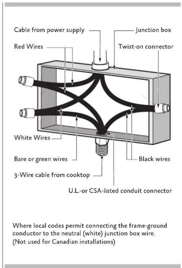
3-Wire branch circuit
Where local codes allow the connection of ground wire from the cooktop to the branch circuit neutral wire (gray or white colored wire) proceed as follows.
- If local codes permit, connect the green GROUND wire from the cooktop to the branch circuit neutral wire (gray or white colored wire).
- Connect the red and black leads from the cooktop to the corresponding leads in the junction box.
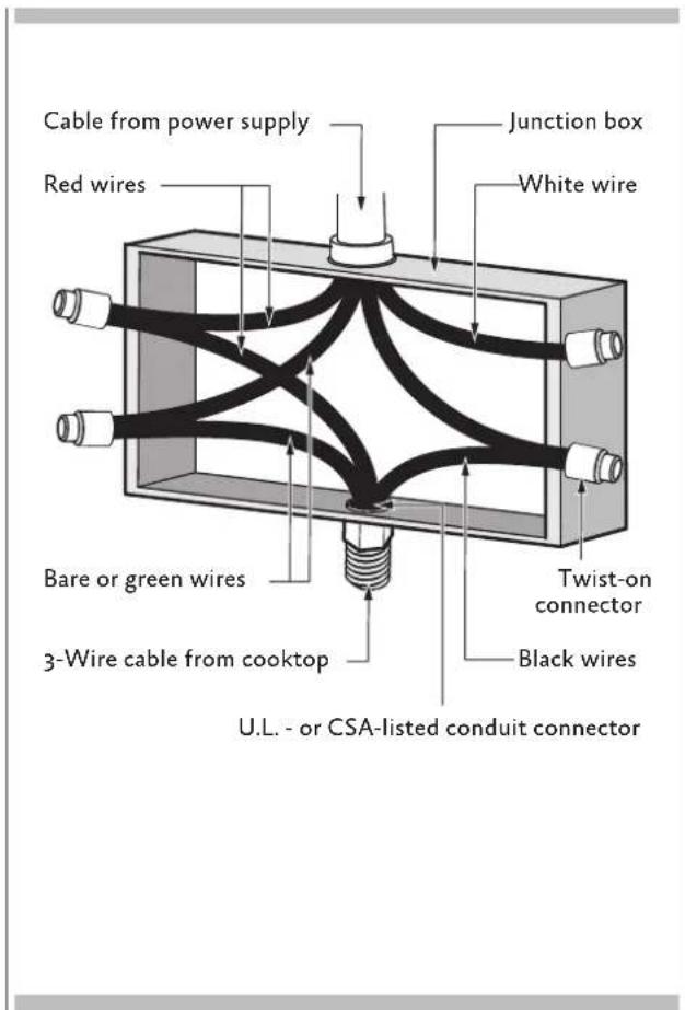
4--Wire branch circuit
- Connect the green ground wire from the cooktop to the ground wire in the junction box (bare or green colored wire).
- Connect the red and black leads from the cooktop to the corresponding leads in the junction box.
- Terminate and insulate the neutral (gray or white colored wire) in the junction box.
CLEANUP, VERIFY POWER
Remove any final packaging materials and protective film from all exterior areas.
Check the electrical requirements for the correct electrical supply and that the cooktop is properly grounded.
Check power at the junction box wires using a voltmeter having a range of 0-250 VAC.
- A 240 Volt supply should read 220 to 240 Volts between the black and red wires (Line to Line).
• A 208 Volt supply should read 190 to 208 Volts between the black and red wires.
FUNCTIONAL TEST
- Fill an induction-capable cooking utensil with 1/2 - 1" [1.2-2.5 cm] of water and place it on one of the cooking zones.
-
Switch the Control ON by touching the [ON OFF] key(1).
-
If the commands are locked, touch the lock key(2) for a few seconds. (See that the LOCK indicator (3) is on and turns off after a few seconds.) Then the controls should respond.
- Touch the zone select key (6) for the cook zone where the utensil is.
- Touch the power slider for that zone and set it to a level between 3 and 9.
- Observe that the display responds to the power setting, and observe that the cooking utensil begins to heat up.
- Touch the selector key (6) for that zone to turn it off.
- Touch the [ON OFF] key to turn the cooktop off.
| Item | Function | Item Function | ||
| 1 | PO | WER key 7 Power slider - minimum power | ||
| 2 | LO | CK key 8 Power slider - maximum power | ||
| 3 | LO | CK indicator 9 Select Power Booster | ||
| 4 | PA | USE key 10 Cooking zone level display | ||
| 5 | Pause and Recall involuntary switch-off indicator | 11 | Power level indicator | |
| 6 | Cooking zone selector (zone ON/OFF) | 12 Cooking zone indicator | ||

CRITERIA
If the controls respond as described and the utensil heats up, then the test is successful.
PARTS LIST
Please visit the Hestan website to access the parts list for your Hestan Indoor product: www.hestanhome.com.
SERVICE
All warranty and non-warranty repairs should be performed by qualified service personnel. To locate an authorized service agent in your zone, contact your Hestan dealer, local representative, or the manufacturer. Before you call, please have the model number and serial number information ready.
Hestan Commercial Corporation
3375 E. La Palma Avenue
Anaheim, CA 92806
(888) 905-7463
AVERTISSEMENT
L'INOBSERVATION DES INFORMATIONS DONNÉES DANS CE MANUEL PEUT ENTRAÎNER UN INCENDIE OU UNE EXPLOSION DE NATURE À CAUSER DES DÉGÂTS MATÉRIELS ET DES BLESSURES GRAVES, VOIRE MORTELLES.
natural_image
Silhouette of a person in motion with a curved arrow, no text or symbols presentnatural_image
Technical line drawing of a rectangular electronic device with a circular component and mounting holes (no text or symbols)EMPLACEMENT DE LA PLAQUE SIGNALÉTIQUE
RESPECT DE LA RÉGLEMENTATION ET DES CODES EN VIGUEUR
36"
DIMENSION DE LA DÉCOUPE
DISPOSITIONS POUR LA DÉCOUPE
LES REVETEMENTS DES MEUBLES ET LE PLAN DE TRAVAIL DOIVENT RESISTER A UNE CHALEUR DE 93° C [200° F]
| Découpe largeur | A | B | C |
| 30"[76,2cm] | 28-3/4" +/- 1/16"[73,0 cm +/- 0,1cm] | 19-7/16" +/- 1/16"[49,4 cm +/- 1mm] | 30"[76,2 cm] min |
| 36"[91,4cm] | 34-5/8" +/- 1/16"[87,9 cm +/- 0,1cm] | 19-7/16" +/- 1/16"[49,4 cm +/- 1mm] | 36"[91,4 cm] min |
PRÉCAUTION
RISQUE DU FAIT DU POIDS EXCESSIF
PIÉCES
ÉTAPE 1
natural_image
Technical diagram of a wall-mounted air conditioner unit with a close-up inset showing internal components (no text or labels)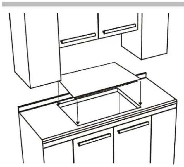
natural_image
Line drawing of a kitchen counter with drawers and appliances (no text or symbols)OUVERTURE DES LIGNES ÉLECTRIQUES
PRÉCAUTION
natural_image
Technical line drawing of a mechanical device casing with internal components and a highlighted section (no text or symbols)AVERTISSEMENT
National Fire Protection Association Batter/march Park Quincy, Massachusetts 02169-7471
Hestan Commercial Corporation
3375 E. La Palma Ave
Anaheim, CA 92806
(888) 905-7463

- INDOOR COOKING
- WARNING
- SAFETY DEFINITIONS
- SAFETY PRECAUTIONS - BEFORE YOU BEGIN
- ELECTRICAL SHOCK HAZARD
- ELECTRICAL GROUNDING
- OVEN MODELS
- RATING LABEL
- REGULATORY / CODE REQUIREMENTS
- CUTOUT REQUIREMENTS
- NOTICE
- Important Preparation Suggestions
- VERTICAL CLEARANCES
- CAUTION
- EXCESSIVE WEIGHT HAZARD
- CUT HAZARD
- STEP 1
- STEP 3
- STEP 4
- STEP 5
- ELECTRIC OPENING
- General information
- 3-Wire branch circuit
- 4--Wire branch circuit
- CLEANUP, VERIFY POWER
- FUNCTIONAL TEST
- CRITERIA
- PARTS LIST
- SERVICE
- AVERTISSEMENT
- RESPECT DE LA RÉGLEMENTATION ET DES CODES EN VIGUEUR
- DISPOSITIONS POUR LA DÉCOUPE
- PRÉCAUTION
- RISQUE DU FAIT DU POIDS EXCESSIF
- ÉTAPE 1
- OUVERTURE DES LIGNES ÉLECTRIQUES
Brand : Hestan
Model : KIC36MS
Category : Cooker