
MKC4150ES - Microwave Oven JENN-AIR - Free user manual and instructions
Find the device manual for free MKC4150ES JENN-AIR in PDF.
| Brand | JENN-AIR |
| Model | MKC4150ES |
| Product Type | Built-in Microwave Oven |
| Category | Microwave Oven |
| Product Dimensions (Width x Height x Depth) | 27" (68.6 cm): 24 1/8" x 14 13/16" x 19 1/16" 30" (76.2 cm): 30" x 14 13/16" x 19 1/16" |
| Trim Frame Dimensions (Width x Height) | 27" (68.6 cm): 26 3/4" x 20 1/8" 30" (76.2 cm): 29 3/4" x 20 1/8" |
| Electrical Supply | 115-120 V AC, 60 Hz, 15 or 20 A |
| Required Circuit | Dedicated circuit exclusive to microwave oven |
| Electrical Outlet | 3-prong, grounded |
| Maximum Weight Supported by Cabinet | 150 lb (68 kg) |
| Minimum Height Above Floor | 36" (91.4 cm) |
| Minimum Clearance Above Opening | 1" (25 mm) |
| Minimum Clearance Below Opening | 1 1/2" (38 mm) above an oven or warming drawer |
| Installation | Above an electric built-in oven or warming drawer. Not designed to be installed under a cooktop. |
| Required Tools | Phillips No. 2 screwdriver, tape measure, square, pencil, drill, 1/16" drill bit, level |
| Provided Parts | Screws, ducts, mounting rails, bottom duct, brackets, trim frame, spacers |
| Grounding | Required. Use cord with ground wire and pin. |
| Cleaning | Disconnect power source before cleaning. Replace parts and panels before operating. |
| Service | Contact local authorized dealer or approved service center. Keep model and serial numbers. |
| General Information | This manual contains important installation instructions. Read carefully before starting. |
Frequently Asked Questions - MKC4150ES JENN-AIR
User questions about MKC4150ES JENN-AIR
0 question about this device. Answer the ones you know or ask your own.
Ask a new question about this device
Download the instructions for your Microwave Oven in PDF format for free! Find your manual MKC4150ES - JENN-AIR and take your electronic device back in hand. On this page are published all the documents necessary for the use of your device. MKC4150ES by JENN-AIR.
USER MANUAL MKC4150ES JENN-AIR
This product is suitable for use above electric built-in ovens or warming drawers. This product is not suitable for use below cooktops. This Built-In Kit is designed for use with Jenn-Air Microwave Oven model specifying JMC3415ES Built-In Kit on the serial tag on the front of the microwave oven.
These Installation Instructions cover different models. The appearance of your particular model may differ slightly from the illustrations in these Installation Instructions.
Please read these instructions thoroughly before beginning installation.
Tools and Parts....2
Location Requirements....3
Minimum Dimensions....3
Product Dimensions....5
Electrical Requirements 5
INSTALLATION INSTRUCTIONS....6
Install Rear and Top Ducts....6
Install Rails and Bottom Duct 7
Install Microwave Oven and Trim Kit Frame 8
Complete Installation 9
To Remove Trim Kit Frame....9
ASSISTANCE 9
SÉCURITÉ DU FOUR À MICRO-ONDES ENCASTRÉ .....10
EXIGENCES D'INSTALLATION ....10
INSTRUCTIONS D'INSTALLATION....14
NOTE: Do not remove protective film from trim kit frame before installing ducts and other mounting hardware. Only remove film just before installing trim on cabinet.
Your safety and the safety of others are very important.
We have provided many important safety messages in this manual and on your appliance. Always read and obey all safety messages.

This is the safety alert symbol.
This symbol alerts you to potential hazards that can kill or hurt you and others.
All safety messages will follow the safety alert symbol and either the word "DANGER" or "WARNING."
These words mean:
DANGER
You can be killed or seriously injured if you don't immediately follow instructions.
WARNING
You can be killed or seriously injured if you don't follow instructions.
All safety messages will tell you what the potential hazard is, tell you how to reduce the chance of injury, and tell you what can happen if the instructions are not followed.
INSTALLATION REQUIREMENTS
Tools and Parts
Gather the required tools and parts before starting installation. Read and follow the instructions provided with any tools listed here.
Tools Needed
■Phillips #2 screwdriver
■Measuring tape
■Combination square/straight edge
Pencil
■Drill (for wall cabinet installations)
■ 116 " (0.16 cm) drill bit (for wall cabinet installations)
■6" (15.2 cm) level
Parts Supplied
Check that all parts are included.

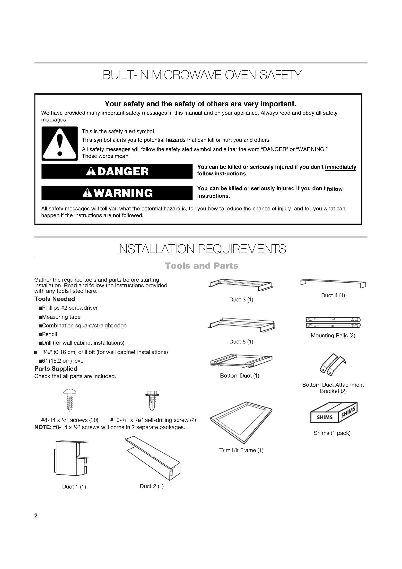
8-14 x 1/2" screws (20) #10-3/4" x 5/16" self-drilling screw (2)
NOTE: #8-14 x 1/2" screws will come in 2 separate packages.
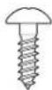
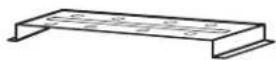
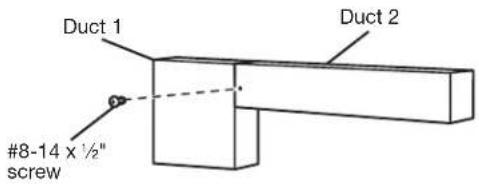
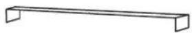
Duct 1 (1)
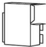
natural_image
Isometric line drawing of a rectangular mechanical part with a flanged side (no text or symbols)Duct 2 (1)
Duct 3 (1)
Duct 4 (1)
Duct 5 (1)
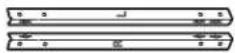
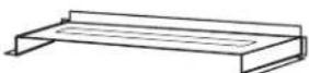
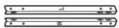
Mounting Rails (2)
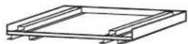
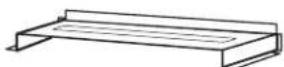
Bottom Duct (1)
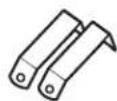
Bottom Duct Attachment Bracket (2)
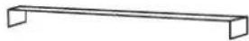
natural_image
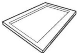
Simple line drawing of a rectangular frame with no text or symbolsTrim Kit Frame (1)

Shims (1 pack)
Location Requirements
The microwave oven may be located in a cabinet and/or above a built-in oven or warming drawer. Check the opening where the microwave oven will be installed. The bottom surface of the cutout must be a minimum of 36" (91.4 cm) above the floor. The location must provide:
■Wood cabinetry.
- Cutout opening that is plumb and square. See “Minimum Installation Clearances” in the “Minimum Dimensions” section.
■Cutout floor that is solid, level, and flush with bottom of cabinet cutout.
■Support for weight of at least 150 lbs (68 kg) which includes microwave oven and items placed inside.
■Grounded electrical outlet. See the "Electrical Requirements" section.
■Minimum installation clearances for installation location. See the "Minimum Dimensions" section.
■Complete enclosure around the recessed portion of the microwave oven, including a solid, full ceiling.
■A level floor – front to back and left to right.
Minimum Dimensions
Minimum Installation Clearances
For proper installation, the following minimum clearances must exist above and below the cutout opening.
Above Cabinet/Storage Drawer Installation Above Oven/Warming Drawer Installation
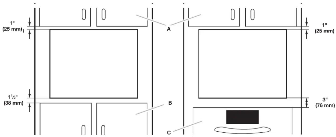
A. Upper cabinet
B. Lower cabinet or storage drawer
C. Lower oven or warming drawer
NOTE: The bottom surface of the cutout must be a minimum of 36" (91.4 cm) above the floor.
Cabinet Requirements
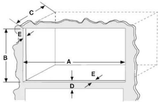
| DIMENSION 27" (68.6 CM)INSTALLATION | 30" (76.2 CM)INSTALLATION | |
| Width(Dimension A) | 26 14 " + 14 ", -0"(66.7 cm + 1.3 cm,-0 cm) | 29 14 " + 14 ", -0"(74.3 + 1.3 cm,-0 cm) |
| Height(Dimension B) | 18 ^13/16 " to 19 116 " (47.8 cm to 48.4 cm)for all installations | |
| Depth (Min.)(Dimension C) | 21 12 " (54.6 cm) with flush receptacle | |
| Minimumclearance betweencutout openings(Dimension D) | 3" (7.6 cm) if installed over oven/warming drawer | |
| Face Frame(Dimension E) | 2" (5.08 cm) min. finished return flushwith opening edge on all 4 sides. | |
IMPORTANT: The oven support surface must be solid, level, and flush with the bottom of the cabinet cutout. The floor must be able to support the microwave oven weight.
NOTE: Cabinet sides must be perpendicular to cabinet floor.
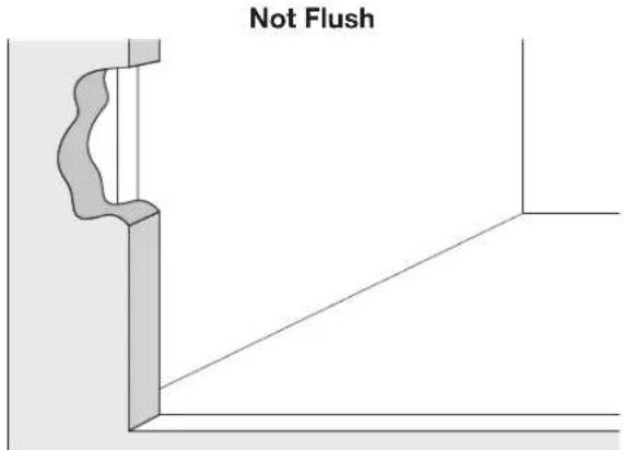
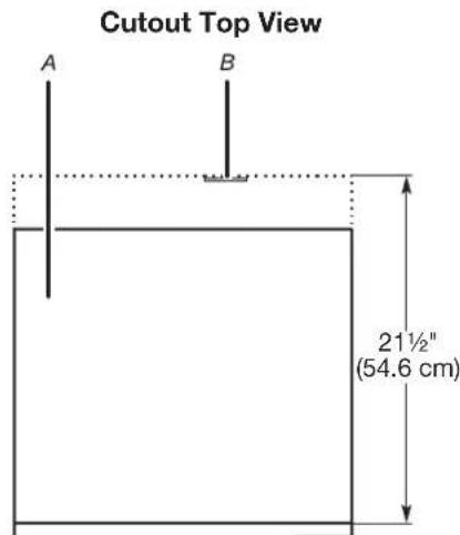
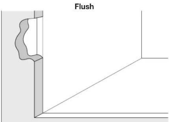
A. Microwave oven
B. Flush receptacle
Recommended Outlet Location
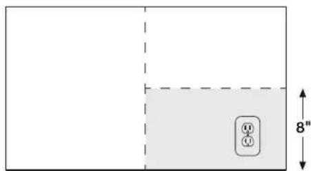
Rear Wall of Cutout
Product Dimensions
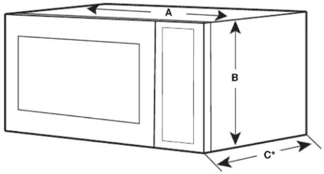
*Measurements include front facing of microwave oven.
| DIMENSION 27" (68.6 CM)INSTALLATION | 30" (76.2 CM)INSTALLATION | |
| Width(Dimension A) | 24 18 " (63.2 cm) 30" (76.2 cm) | |
| Height(Dimension B) | 14 ^13/_16 " (37.6 cm) | |
| Depth(Dimension C) | 19 ^1/_15 " (48.4 cm) | |
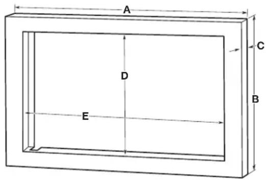
Trim Kit Frame Dimensions
| DIMENSION 27" (68.6 CM)INSTALLATION | 30" (76.2 CM)INSTALLATION | |
| A 2634 " (68 | 0 cm) 2934 " (75.6 cm) | |
| B 2018 " (51 | 1 cm) 2018 " (51.1 cm) | |
| C 114 " (3.2 cm) 114 " (3.2 cm) | ||
| D 14716 " (36.7 cm) 14716 " (36.7 cm) | ||
| E 2434 " (62 | 9 cm) 2434 " (62.9 cm) | |
Electrical Requirements
WARNING

Electrical Shock Hazard
Plug into a grounded 3 prong outlet.
Do not remove ground prong.
Do not use an adapter.
Do not use an extension cord.
Failure to follow these instructions can result in death, fire, or electrical shock.
Observe all governing codes and ordinances.
Required:
■A 3 prong, polarized 115- to 120-volt, 60 Hz, AC-only,
15- or 20-amp electrical outlet at the rear of the opening.
Recommended:
■A time-delay fuse or time-delay circuit breaker
■A separate circuit serving only this microwave oven
GROUNDING INSTRUCTIONS
■ For all cord connected appliances:
The microwave oven must be grounded. In the event of an electrical short circuit, grounding reduces the risk of electric shock by providing an escape wire for the electric current. The microwave oven is equipped with a cord having a grounding wire with a grounding plug. The plug must be plugged into an outlet that is properly installed and grounded.
WARNING: Improper use of the grounding plug can result in a risk of electric shock. Consult a qualified electrician or serviceman if the grounding instructions are not completely understood, or if doubt exists as to whether the microwave oven is properly grounded.
Do not use an extension cord. If the power supply cord is too short, have a qualified electrician or serviceman install an outlet near the microwave oven.
SAVE THESE INSTRUCTIONS
INSTALLATION INSTRUCTIONS
WARNING
Excessive Weight Hazard
Use two or more people to move and install microwave oven.
Failure to do so can result in back or other injury.
IMPORTANT: To prevent damage, do not remove protective film on the frame.
- Empty microwave oven cavity of any loose contents, including turntable.
- Ensure floor of cabinet is level.
Install Rear and Top Ducts
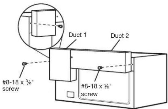
- Insert the edge of duct 1 into duct 2. Fasten together with 1 #8-14 x 1/2" screw.
- Remove the 2 existing #8-18 x 3/8 screws at upper right and left corners of the microwave oven.
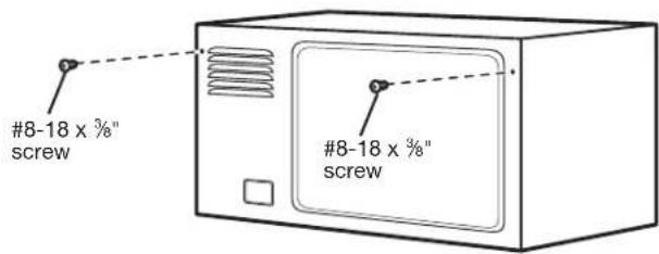
- Secure ducts 1 and 2 with #8-18 x 38 " screws just removed from the microwave oven.
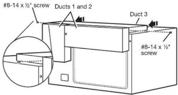
- Position duct 3 on the top of the microwave oven, inserting the edge of ducts 1 and 2 into duct 3. Secure duct 3 to ducts 1 and 2 using 2 #8-14 x 1/2" screws.
- Position duct 4 on top of the microwave oven and insert it into duct 3. Secure duct 4 to duct 3 using 2 #8-14 x 1/2" screws.
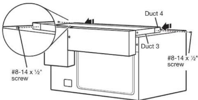
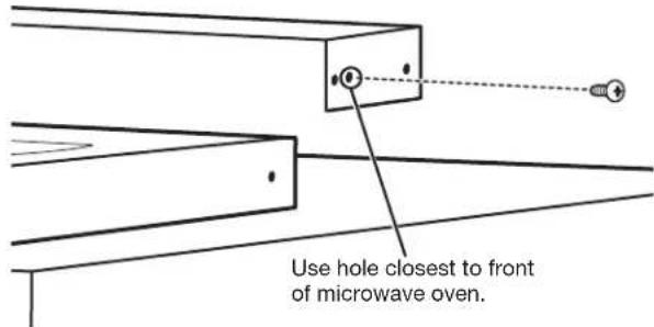
IMPORTANT: The double holes on duct 4 go toward the back of the microwave oven. On each side of duct 4, screw 1 #8-14 x ½" screw into the front-most hole of the double hole.
- Position duct 5 on top of the microwave oven and insert it into duct 4. Secure duct 5 using 3 #8-14 x 1/2" screws provided.
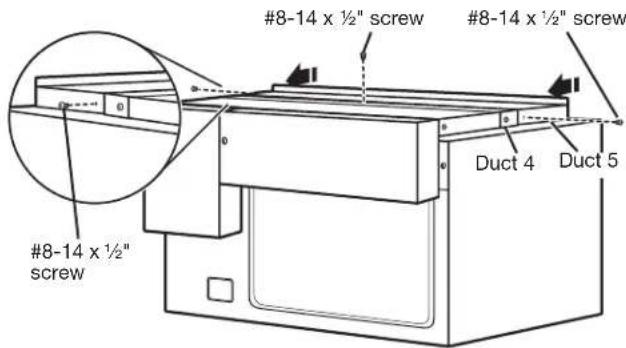
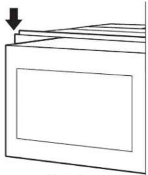
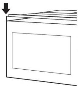
IMPORTANT: The flanges of duct 5 go under duct 4. The front edge of the duct should be flush with the microwave oven itself and not the door.
natural_image
Simple line drawing of a cabinet or storage unit with a downward arrow indicating compression (no text or symbols)Correct
natural_image
Simple line drawing of a rectangular box with a downward arrow pointing to its top surface (no text or symbols)Incorrect
Install Rails and Bottom Duct
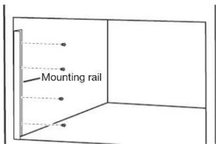
- Make sure notch is at bottom of rail. Position the rail marked L on the left side of the cabinet with the bottom edge resting on the cabinet floor. Verify rail is flush with the face of the cabinet before proceeding. Drill pilot holes. Attach mounting rail using 4 #8-14 x ½" screws.
NOTE: Drive screws in the center of the holes in the mounting rail.
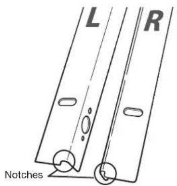
Right RailLeft Rail
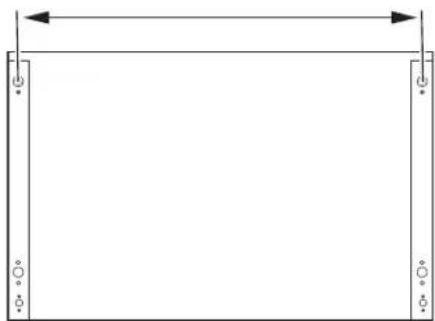
- Repeat Step 1 on right side of cabinet. Use the following chart and illustration to measure the distance between center of mounting rail holes. Use shims if measured distance is incorrect.
| 27" (68.6 CM)INSTALLATION | 30" (76.2 CM)INSTALLATION |
| 25 12 " (64.8 cm) 28 12 " (72.4 cm) |
natural_image
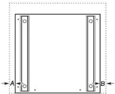
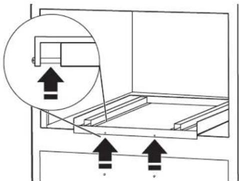
Simple line drawing of a rectangular frame with vertical supports and a horizontal double-headed arrow (no text or symbols)- Position bottom duct in cabinet so that each side of duct is the same distance from the side walls and spacers are flush with cabinet.
natural_image
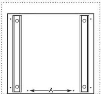
Pure geometric diagram of a rectangular frame with two vertical supports and labeled points A and B, no text or symbols present.Dimension A must equal Dimension B.
Spacers behind holes
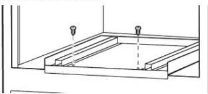
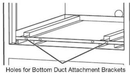
- Drill pilot holes for 2 holes on the front of the bottom duct.
natural_image
Simple line drawing of a square frame with vertical and horizontal bars, labeled with dimension A (no text or symbols beyond basic geometry)A. Pilot holes
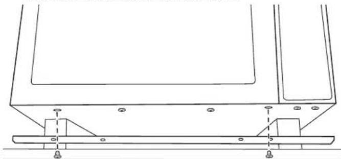
- Secure bottom duct to cabinet floor with 2 #8-14 x 1/2" screws on front of bottom duct.
natural_image
Pure technical line drawing of a structural frame with two bolt holes (no text or symbols)Install Microwave Oven and Trim Kit Frame
- Moving from right to left, remove the third and sixth screws from the front of the microwave bottom plate.
NOTE: Do not remove screws from door.
natural_image
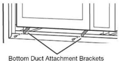
Technical line drawing of a structural support frame with mounting feet and base plate (no text or symbols)- Use the screws just removed to install the Bottom Duct Attachment Brackets in the same holes the screws were removed from.
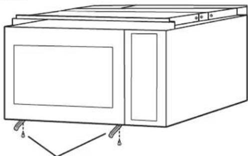
natural_image
Line drawing of a simple kitchen appliance with doors and wheels (no text or symbols)Bottom Duct Attachment Brackets
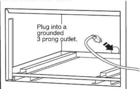
WARNING

Electrical Shock Hazard
Plug into a grounded 3 prong outlet.
Do not remove ground prong.
Do not use an adapter.
Do not use an extension cord.
Failure to follow these instructions can result in death, fire, or electrical shock.
- With the microwave oven near the opening, plug the microwave oven into the grounded 3 prong outlet.
NOTE: To avoid pinching of the power cord, make sure it is away from the bottom duct.
- Place the microwave oven in the cabinet on the risers. Make sure the feet are firmly seated in embossments located on risers. Verify that microwave oven is level.
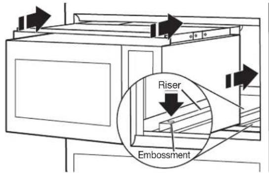
- Secure the microwave oven to the bottom duct. Using 2 #10-3/4" x 5/16" self-drilling screws, fasten the Bottom Duct Attachment Brackets to the first and fourth holes in the front of the bottom duct.
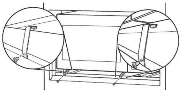
natural_image
Technical line drawing of a cylindrical mechanical component with two circular inset views showing internal components (no text or symbols)- Remove protective film from trim kit frame.
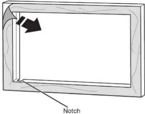
- Align trim kit frame studs with corresponding holes in mounting rails and snap into place.
NOTE: Top and bottom studs are different distances from the edge, so the trim kit frame will install in only 1 way. Ensure notch is in lower-left corner.
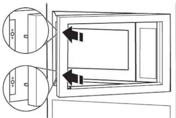
natural_image
Diagram of a door frame with two inset views showing internal components (no text or symbols)
natural_image
Simple line drawing of a rectangular frame with a central rectangle and a smaller side (no text or symbols)Installed Microwave Oven
Complete Installation
- Install the turntable in the microwave oven.
-
Check the operation of microwave oven by placing 1 cup (250 mL) of water on the turntable and programming cook time of 1 minute at 100% power.
-
If the microwave oven does not operate:
■Check that a household fuse has not blown or a circuit breaker tripped. Replace the fuse or reset the circuit breaker. If the problem continues, call an electrician.
■Check that the power supply cord is plugged into a grounded 3 prong outlet.
■See the Use and Care Guide for troubleshooting information.
Installation is now complete.
Save these Installation Instructions for future use.
To Remove Trim Kit Frame
Firmly grasp top of trim at vent area and pull away.
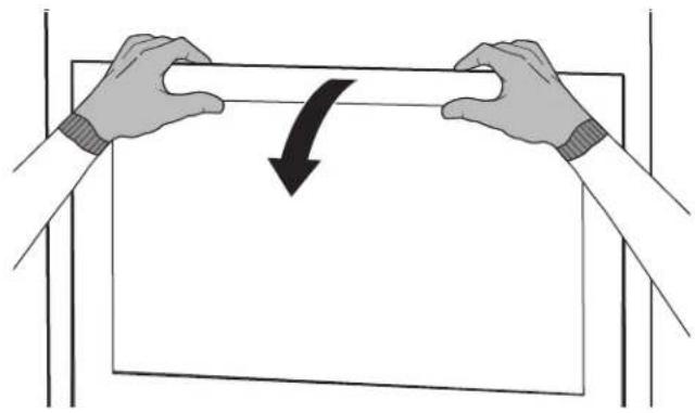
natural_image
Illustration of two hands holding a rectangular object with a curved arrow indicating rotation or compression (no text or symbols)ASSISTANCE
Call your authorized dealer or service center. When you call, you will need the microwave oven model number and serial number. Both numbers can be found on the model and serial number plate, which is located behind the microwave oven door on the front frame of the microwave oven.
If you need additional assistance, call us at our toll-free number or visit our website listed in the Use and Care Guide.
SÉCURITÉ DU FOUR À MICRO-ONDES ENCASTRÉ
natural_image
Pure technical line drawing of a rectangular mechanical part with no text or symbolsConduit 2 (1)

Conduit 3 (1)
Conduit 4 (1)
Conduit 5 (1)
natural_image
Simple line drawing of a rectangular frame with no text or symbolsnatural_image
Simple line drawing of stacked rectangular boxes with a downward arrow indicating compression (no text or symbols)Correct

natural_image
Simple line drawing of a rectangular box with a downward arrow pointing to its top surface (no text or symbols)Incorrect
natural_image
Simple line drawing of a rectangular frame with vertical supports and a horizontal double-headed arrow (no text or symbols)natural_image
Pure diagram of a rectangular frame with vertical and horizontal bars, no text or symbols presentnatural_image
Technical diagram showing a structural assembly with arrows indicating upward motion (no text or symbols present)natural_image
Simple line drawing of a rectangular frame with two vertical bars and centerlines, labeled 'A' at the bottom (no text or symbols within the frame)A. Avant-trous
natural_image
Technical line drawing of a structural support frame with two bolt holes (no text or symbols)natural_image
Technical line drawing of a mechanical assembly with mounting brackets and mounting holes (no text or symbols)natural_image
Line drawing of a microwave oven with doors and control panel (no text or symbols)natural_image
Technical line drawing of a cylindrical mechanical component with two circular inset views (no text or symbols)natural_image
Diagram of a door frame with two inset views showing internal components (no text or symbols)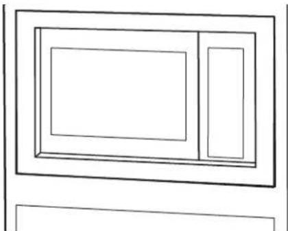
natural_image
Simple line drawing of a rectangular frame with two internal rectangles, no text or symbols present.natural_image
Illustration of two hands holding a rectangular object with a curved arrow indicating rotation or change (no text or symbols)ASSISTANCE


- INSTALLATION INSTRUCTIONS....6
- ASSISTANCE 9
- SÉCURITÉ DU FOUR À MICRO-ONDES ENCASTRÉ .....10
- EXIGENCES D'INSTALLATION ....10
- INSTRUCTIONS D'INSTALLATION....14
- Your safety and the safety of others are very important.
- DANGER
- WARNING
- INSTALLATION REQUIREMENTS
- Tools and Parts
- Tools Needed
- Parts Supplied
- 8-14 x 1/2" screws (20) #10-3/4" x 5/16" self-drilling screw (2)
- Location Requirements
- Minimum Dimensions
- Minimum Installation Clearances
- Cabinet Requirements
- Product Dimensions
- Electrical Requirements
- Electrical Shock Hazard
- Required:
- Recommended:
- GROUNDING INSTRUCTIONS
- ■ For all cord connected appliances:
- SAVE THESE INSTRUCTIONS
- INSTALLATION INSTRUCTIONS
- Excessive Weight Hazard
- Install Rear and Top Ducts
- Install Rails and Bottom Duct
- Install Microwave Oven and Trim Kit Frame
- Complete Installation
- To Remove Trim Kit Frame
- ASSISTANCE
- SÉCURITÉ DU FOUR À MICRO-ONDES ENCASTRÉ
Brand : JENN-AIR
Model : MKC4150ES
Category : Microwave Oven