RL75eN - Boiler Rinnai - Free user manual and instructions
Find the device manual for free RL75eN Rinnai in PDF.

| Product Type | Gas tankless water heater, direct vent |
| Brand / Model | Rinnai RL75eN |
| Dimensions (H x W x D) | 20.1 x 14.2 x 8.7 inches (511 x 361 x 221 mm) |
| Weight | 43.6 lb (19.8 kg) |
| Power Supply | 120 V AC, 60 Hz, 76 W (normal), 2 W (standby) |
| Max Thermal Output | 180,000 Btu/h (52.7 kW) |
| Hot Water Flow Rate | 0.26 - 7.5 GPM (1.0 - 28.5 L/min) |
| Temperature Setting | 98°F (37°C) to 160°F (71°C) with MCC-91 controller |
| Main Features | Instant hot water production, electronic temperature control, built-in freeze protection (-4°F/-20°C), recirculation mode (Economy/Comfort), compatible with multiple controllers |
| Maintenance | Flush heat exchanger with white vinegar if LC code appears, clean water inlet filter, manual drain if freeze risk |
| Cleaning | Clean water filter regularly; use a leak detector for gas connections |
| Safety | Pressure relief valve (150 psi), flame detection, automatic shutdown on overheat, freeze protection, gas safety switch |
| Main Spare Parts | Printed circuit board, fan/motor, heat exchanger, ignition electrodes, water flow servo, water filter |
| Repairability | Interventions by a qualified professional; original Rinnai parts required for warranty |
| General Information | Outdoor installation only (e model), certified for mobile homes, compliant with NOx 20 ppm, heat exchanger warranty 12 years (residential) |
Frequently Asked Questions - RL75eN Rinnai
User questions about RL75eN Rinnai
0 question about this device. Answer the ones you know or ask your own.
Ask a new question about this device
Download the instructions for your Boiler in PDF format for free! Find your manual RL75eN - Rinnai and take your electronic device back in hand. On this page are published all the documents necessary for the use of your device. RL75eN by Rinnai.
USER MANUAL RL75eN Rinnai
Direct Vent Tankless Water Heater Installation and Operation Manual
natural_image
Line drawing of a rectangular industrial or gas storage unit with control panel and mounting base (no text or symbols)
natural_image
Line drawing of a portable water heater with ventilation slots and control panel (no text or symbols)
Low Lead Content
NSF/ANSI 372

SANITATION

ANS Z21.10.3 • CSA 4.3
READ ALL OF THE INSTRUCTIONS THOROUGHLY BEFORE INSTALLING OR OPERATING THIS WATER HEATER.
This manual provides information on the installation, operation, and maintenance of the water heater. For proper operation and safety, it is important to follow the instructions and adhere to the safety precautions.
A licensed professional must install the water heater according to the exact instructions on pages 4-30.
The consumer must read the entire manual to properly operate the water heater and to have regular maintenance performed.

WARNING
If the information in these instructions is not followed exactly, a fire or explosion may result causing property damage, personal injury, or death.
— Do not store or use gasoline or other flammable vapors and liquids in the vicinity of this or any other appliance.
— WHAT TO DO IF YOU SMELL GAS
- Do not try to light any appliance.
- Do not touch any electrical switch; do not use any phone in your building.
- Immediately call your gas supplier from a neighbor's phone. Follow the gas supplier's instructions.
- If you cannot reach your gas supplier, call the fire department.
— Installation and service must be performed by a licensed professional.
This entire manual must be left for the consumer. The consumer must read and refer to this manual for proper operation and to maintain the water heater.
Table of Contents
Table of Contents 2
Safety Behaviors and Practices for the
Consumer and Installer 3
Installation Instructions
(for the licensed professional) 4
Prepare for Installation....5
Determine Installation Location 6
Freeze Protection....11
Checklist to Determine Installation Location... 12
Mount to Wall....12
Remove the Front Panel 12
Installation of Venting (indoor models only) ... 13
Condensate (indoor models only)....15
Checklist for Venting and Condensate
(indoor models only)....15
Installation of Plumbing....16
Checklist for Plumbing 19
Installation of Gas Supply 19
Connect Electricity 21
Adjust for High Altitude 21
Adjust for Vent Length (indoor models only) ..21
Checklist for Gas and Electricity....21
Installation of Temperature Controller......22
Final Checklist....24
Technical Data 25
Specifications 25
Dimensions....26
Pressure Drop and Water Flow Curves......27
Ladder Diagram....28
Recirculation Mode....29
Operation Instructions ....31
Consumer Operation Guidelines for the
Safe Operation of your Water Heater....32
How to Use the Temperature Controller......33
How to Set the Temperature ....34
Diagnostic Codes....36
Required Maintenance....39
Freeze Protection and Winterization .....40
Flushing the Heat Exchanger......41
Manual Draining of the Water Heater .....42
State Regulations....43
Replacement Parts 44
Consumer Warranty 45
French Version....48
NOTICE: Rinnai sometimes shares customer contact information with businesses that we believe provide products or services that may be useful to you. By providing this information, you agree that we can share your contact information for this purpose. If you prefer not to have your information shared with these businesses, please contact customer service and ask not to have your information shared. We will however, continue to contact you with information relevant to the product(s) you registered and/or your account with us.
If you have any questions or feel that the manual is incomplete contact Rinnai at 1-800-621-9419.
Important Safety Information
Safety Definitions

This is the safety alert symbol. This symbol alerts you to potential hazards that can kill or hurt you and others.
! DANGER
WARNING
CAUTION
Indicates an imminently hazardous situation which, if not avoided, will result in death or serious injury.
Indicates a potentially hazardous situation which, if not avoided, could result in death or serious injury.
Indicates a potentially hazardous situation which, if not avoided, could result in minor or moderate injury. It may also be used to alert against unsafe practices.
Safety Behaviors and Practices for the Consumer and Installer

WARNING
- Before operating, smell all around the appliance area for gas. Be sure to smell next to the floor because some gas is heavier than air and will settle on the floor.
- Keep the area around the appliance clear and free from combustible materials, gasoline, and other flammable vapors and liquids.
- Combustible construction refers to adjacent walls and ceiling and should not be confused with combustible or flammable products and materials. Combustible and/or flammable products and materials should never be stored in the vicinity of this or any gas appliance.
- Always check the water temperature before entering a shower or bath.
-
To protect yourself from harm, before performing maintenance:
Turn off the electrical power supply by unplugging the power cord or by turning off the electricity at the circuit breaker. (The temperature controller does not control the electrical power.)
Turn off the gas at the manual gas valve, usually located immediately below the water heater.
Turn off the incoming water supply. This can be done at the isolation valve immediately below the water heater or by turning off the water supply to the building. -
Use only your hand to push in or turn the gas control knob. Never use tools. If the knob will not push in or turn by hand, do not try to repair it; call a licensed professional. Force or attempted repair may result in a fire or explosion.
- Do not use this appliance if any part has been under water. Immediately call a licensed professional to inspect the appliance and to replace any part of the control system and any gas control which has been under water.
- Do not use substitute materials. Use only parts certified for the appliance.
- Should overheating occur or the gas supply fail to shut off, turn off the manual gas control valve to the appliance.
- Do not adjust the DIP switch unless specifically instructed to do so.
- Do not use an extension cord or an adapter plug with this appliance.
- Any alteration to the appliance or its controls can be dangerous and will void the warranty.

CAUTION
- BURN HAZARD. Hot exhaust and vent may cause serious burns. Keep away from water heater unit. Keep small children and animals away from the unit.
- Hot water outlet pipes leaving the unit can be hot to touch. In residential applications, insulation must be used for hot water pipes below 36" due to burn risk to children.

WARNING
California law requires this notice to be provided:
California Proposition 65:
This product contains chemicals known to the state of California to cause cancer, birth defects, or other reproductive harm.
Installation Instructions
It is recommended that a licensed professional install the appliance, inspect it, and leak test it before use. The warranty may be voided due to any improper installation.
The installer should have skills such as:
- Gas sizing.
- Connecting gas lines, water lines, valves, and electricity.
- Knowledge of applicable national, state, and local codes.
- Installing venting through a wall or roof.
- Training in installation of tankless water heaters. (Training can be accessed on-line at www.trainingevents.rinnai.us)
Type of installation
- For installation in residential and commercial applications.
- Certified for installation in manufactured (mobile) homes.
Installation Steps
Prepare for Installation 5
Determine Installation Location....6
Checklist to Determine Installation Location ... 12
Mount to Wall....12
Remove the Front Panel 12
Installation of Venting (indoor models only) ...13
Condensate (indoor models only)....15
Checklist for Venting and Condensate
(Indoor models only)....15
Installation of Plumbing 16
Checklist for Plumbing 19
Installation of Gas Supply....19
Connect Electricity ......21
Adjust for High Altitude 21
Adjust for Vent Length (indoor models only) ..21
Checklist for Gas and Electricity....21
Installation of Temperature Controller......22
Final Checklist....24
General Instructions Installer Qualifications
DO NOT
- Do not install the RL75i, RL94i, or the RLX94i outdoors.
- Do not install the RL75e or the RL94e indoors.
- Do not install the appliance in an area where water leakage of the unit or connections will result in damage to the area adjacent to the appliance or to lower floors of the structure. When such locations cannot be avoided, it is recommended that a suitable drain pan, adequately drained, be installed under the appliance. The pan must not restrict combustion air flow.
- Do not obstruct the flow of combustion and ventilation air. Combustion air shall not be supplied from occupied spaces.
- Do not use this appliance in an application such as a pool or spa heater that uses chemically treated water. (This appliance is suitable for filling large or whirlpool spa tubs with potable water.)
- Do not use substitute parts that are not authorized for this appliance.
MUST DO
- The installation must conform with local codes or, in the absence of local codes, with the National Fuel Gas Code, ANSI Z223.1/NFPA 54, or the Natural Gas and Propane Installation Code, CSA B149.1. If installed in a manufactured home, the installation must conform with the Manufactured Home Construction and Safety Standard, Title 24 CFR, Part 3280 and/or CAN/SCA Z240 MH Series, Mobile Homes.
- The appliance, when installed, must be electrically grounded in accordance with local codes or, in the absence of local codes, with the National Electrical Code, ANSI/NFPA 70, or the Canadian Electrical Code, CSA C22.1.
- The appliance and its appliance main gas valve must be disconnected from the gas supply piping system during any pressure testing of that system at test pressures in excess of 1/2 psi (3.5 kPa) (13.84 in W.C.).
General Instructions (continued)
- The appliance must be isolated from the gas supply piping system by closing its individual manual shutoff valve during any pressure testing of the gas supply piping system at test pressures equal to or less than 1/2 psi (3.5 kPa) (13.84 in W.C.).
- You must follow the installation instructions and those in Care and Maintenance for adequate combustion air intake and exhaust.
INFORMATION
- If a water heater is installed in a closed water supply system, such as one having a backflow preventer in the cold water supply line, means shall be provided to control thermal expansion. Contact the water supplier or local plumbing inspector on how to control thermal expansion.
- Should overheating occur or the gas supply fail to shut off, turn off the manual gas control valve to the appliance.
- Keep the air intake location free of chemicals such as chlorine or bleach that produce fumes. These fumes can damage components and reduce the life of your appliance.
Prepare for installation
Parts included
- Tankless water heater
• Color coded cold (blue) and hot (red) isolation valves - Pressure relief valve
- MC-91-2 temperature controller (integrated into indoor models; provided with outdoor models)
Tools needed
- Pipe wrenches (2)
- Gloves
- Adjustable pliers
- Safety glasses
- Screwdrivers (2)
- Level
- Wire cutters
Tools that might be needed
- Hammer drill with concrete bits
- Core drill with diamond head
- Saw
- Torch set
- Threading machine with heads and oiler
• Copper tubing cutter - Steel pipe cutter
Materials needed
- Soap or gas leak detector solution
- Teflon tape (recommended) or pipe compound
- Approved venting
Materials that may be needed
- Heat tape
- 5/8" ID PVC flexible tubing
- Pipe insulation
• 2 conductor 22 AWG wire for controller
• Electrical wire and conduit per local code
- Single gang electrical box
• Concrete wall anchors
- Wire nuts
- Optional pipe cover
• Unions and drain valves
- Optional temperature controller
Determine Installation Location
You must ensure that clearances will be met and that the vent length will be within required limits. Consider the installation environment, water quality, and need for freeze protection. Requirements for the gas line, water lines, electrical connection, and condensate disposal can be found in their respective installation sections of this manual.
Water Quality
Consideration of care for your water heater should include evaluation of water quality.
The water must be potable, free of corrosive chemicals, sand, dirt, or other contaminates. It is up to the installer to ensure the water does not contain corrosive chemicals, or elements that can affect or damage the heat exchanger. Water that contains chemicals exceeding the levels below affect and damage the heat exchanger. Replacement of the heat exchanger due to water quality damage is not covered by the warranty.
| Maximum Level | |
| Total Hardness Up to 200 mg / L | |
| Aluminum * Up to 0.2 mg / L | |
| Chlorides * Up to 250 mg / L | |
| Copper * Up to 1.0 mg / L | |
| Dissolved Carbon Dioxide (CO2) Up to 15.0 mg / L or PPM | |
| Iron * Up to 0.3 mg / L | |
| Manganese * Up to 0.05 mg / L | |
| pH * 6.5 to 8.5 | |
| TDS (Total Dissolved Solids) * Up to 500 mg / L | |
| Zinc * Up to 5 mg / L | |
* Source: Part 143 National Secondary Drinking Water Regulations
If you install this water heater in an area that is known to have hard water or that causes scale build-up the water must be treated and/or the heat exchanger flushed regularly.
When scale build-up in the heat exchanger begins to affect the performance of the water heater, a diagnostic code "LC#" will display. Flush the heat exchanger to prevent damage to it. Scale build up is caused by hard water set at a high temperature.
Rinnai offers Southeastern Filtration's "ScaleCutter Water Conditioning System" that offers superior lime scale prevention and corrosion control by feeding a blend of control compounds into the cold water supply.
| Part Number | Description |
| 103000038 | Southeastern FiltratrionScaleCutter System 3/4” Feed |
| 103000039 | ScaleCutter Refill |
Environment
Air surrounding the water heater, venting, and vent termination(s) is used for combustion and must be free of any compounds that cause corrosion of internal components. These include corrosive compounds that are found in aerosol sprays, detergents, bleaches, cleaning solvents, oil based paints/ varnishes, and refrigerants. The air in beauty shops, dry cleaning stores, photo processing labs, and storage areas for pool supplies often contains these compounds. Therefore it is recommended that outdoor models be used for these locations where possible.
The water heater, venting, and vent termination(s) should not be installed in any areas where the air may contain these corrosive compounds. If it is necessary for a water heater to be located in areas which may contain corrosive compounds, the following instructions are strongly recommended.
IMPORTANT CONSIDERATIONS FOR:
Indoor/Internal Water Heaters
- DO NOT Install in areas where air for combustion can be contaminated with chemicals.
- Before installation, consider where air has the ability to travel within the building to the water heater.
- Where possible, install the water heater in a sealed closet so that it is protected from the potential of contaminated indoor air.
- Chemicals that are corrosive in nature should not be stored or used near the water heater.
Outdoor/External Water Heaters and Vent Terminations of Indoor/Internal Water Heaters
- Install the water heater as far away as possible from exhaust vent hoods.
- Install as far away as possible from air inlet vents. Corrosive fumes may be released through these vents when air is not being brought in through them.
- Chemicals that are corrosive in nature should not be stored or used near the water heater or vent termination.
Damage and repair due to corrosive compounds in the air is not covered by warranty.
Terminal Clearances
For indoor models, you must install a vent termination to bring in combustion air and expel exhaust.

text_image
TERMINATION Clearance in Ref. A also applies to anticipated snow line SNOW Inside corner detail V G A H C V Fixed closed Operable F B B B V Operable Fixed closed V A X M V K Regulator vent outlet AIR SUPPLY INLET VENT TERMINAL AREA WHERE TERMINAL IS NOT PERMITTED| Direct Vent (Indoor Unit) Other than direct vent (Outdoor unit) | |||||
| Ref | Description | Canadian Installations (CSA B149.1) | US Installations (ANSI Z223.1 / NFPA 54) | Canadian Installations (CSA B149.1) | US Installations (ANSI Z223.1 / NFPA 54) |
| A | Clearance above grade, veranda, porch, deck, or balcony | 12 inches (30 cm) | 12 inches (30 cm) | 12 inches (30 cm) | 12 inches (30 cm) |
| B | Clearance to window or door that may be opened | 36 inches (91 cm) | 12 inches (30 cm) | 6 in (15 cm) for appliances ≤ 10,000 Btuh (3 kW), 12 in (30 cm) for appliances > 10,000 Btuh (3 kW) and ≤ 100,000 Btuh (30 kW), 36 in (91 cm) for appliances >100,000 Btuh (30 kW) | 4 ft (1.2 m) below or to side of opening; 1 ft (300 mm) above opening |
| C | Clearance to permanently closed window | * | * | * | * |
| D | Vertical clearance to ventilated soffit, located above the terminal within a horizontal distance of 2 feet (61 cm) from the center line of the terminal | * | * | * | * |
| E | Clearance to unventilated soffit | * | * | * | * |
| F | Clearance to outside corner | * | * | * | * |
| G | Clearance to inside corner | * | * | * | * |
| H | Clearance to each side of center line extended above meter/regulator assembly | * | * | * | * |
| I | Clearance to service regulator vent outlet | Above a regulator within 3 ft (91 cm) horizontally of the vertical center line of the regulator vent outlet to a maximum vertical distance of 15 ft (4.5 m) | * | Above a regulator within 3 ft (91 cm) horizontally of the vertical center line of the regulator vent outlet to a maximum vertical distance of 15 ft (4.5 m) | * |
| J | Clearance to nonmechanical air supply inlet to building or the combustion air inlet to any other appliance | 36 inches (91 cm) 12 inches (30 cm) | 6 in (15 cm) for appliances ≤ 10,000 Btuh (3 kW), 12 in (30 cm) for appliances > 10,000 Btuh (3 kW) and ≤ 100,000 Btuh (30 kW), 36 in (91 cm) for appliances >100,000 Btuh (30 kW) | 4 ft(1.2 m) below or to side of opening; 1 ft (300 mm) above opening | |
| K | Clearance to a mechanical air supply inlet | 6 ft (1.83 m) | 3 ft (91 cm) above if within 10 ft (3 m) horizontally | 6 ft (1.83 m) | 3 ft (91 cm) above if within 10 feet (3 m) horizontally |
| L | Clearance above paved sidewalk or paved driveway located on public property | 7 ft (2.13 m) 1 | * | 7 ft (2.13 m) [1] | 7 ft. (2.13 m) |
| M | Clearance under veranda, porch, deck, or balcony | 12 inches (30 cm) 2 | * | 12 inches (30 cm) [2] | * |
[1] A vent shall not terminate directly above a sidewalk or paved driveway that is located between two single family dwellings and serves both dwellings.
[2] Permitted only if veranda, porch, deck, or balcony is fully open on a minimum of two sides beneath the floor.
* For clearances not specified in ANSI Z223.1/NFPA 54, clearances are in accordance with local installation codes and the requirements of the gas supplier. Clearance to opposite wall is 24 inches (60 cm).
Additional clearances - RL75i, RL94i, RLX94i
Check to determine whether local codes supersede these clearances.
- Avoid termination locations near a dryer vent.
- Avoid termination locations near commercial cooking exhaust.
- You must install a vent termination at least 12 inches above the ground.
Important considerations for locating vent termination under a soffit (ventilated or unventilated or eave vent; or to a deck or porch)
- Do not install vent termination under a soffit vent such that exhaust can enter the soffit vent
- Install vent termination such that exhaust and rising moisture will not collect under eaves. Discoloration to the exterior of the building could occur if installed too close.
- Do not install the vent termination too close under the soffit where it could present recirculation of exhaust gases back into the combustion air intake part of the termination.
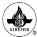
text_image
(0.30 m) to an inside corner 12" V V 12" (0.30 m) between terminals at same level INSIDE CORNER
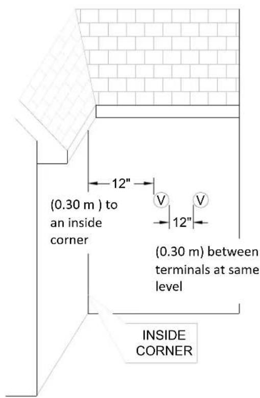
text_image
(1.52 m) between terminals at different levels 60" (1.52 m) vertically between terminals V V 60" (1.52 m)
text_image
(0.61 m) to wall or parapet 24"
text_image
(0.30 m) between terminals at same level 12"Additional clearances
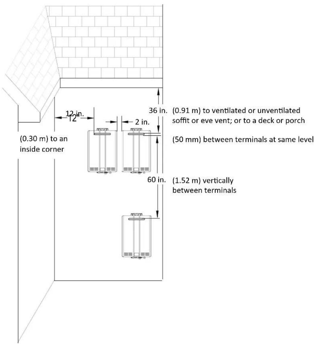
RL75e, RL94e
Local codes supersede these clearances.
- Avoid termination locations near a dryer vent.
- Avoid termination locations near commercial cooking exhaust.
- Avoid termination locations near any air inlets.
text_image
(0.30 m) to an inside corner 12 in. 12" 36 in. (0.91 m) to ventilated or unventilated soffit or eve vent; or to a deck or porch (50 mm) between terminals at same level 2 in. 60 in. (1.52 m) vertically between terminalsUnit clearances
text_image
to top to side to front to ground/bottomIndoor models: RL75i, RL94i, RLX94i
| to Combustibles inches (mm) | to Non-Combustibles inches (mm) | |
| Top of Heater | 6 * (152) | 2 *(51) |
| Back of Heater | 0 (zero) | 0 (zero) |
| Front of Heater | 6 (152) | 6 (152) |
| Sides of Heater | 2 (51) | 1/2 (13) |
| Ground/Bottom | 12 (305) | 12 (305) |
| Vent | 0 (zero) | 0 (zero) |
* 0 inches from vent components and condensate drain line.
The clearance for servicing is 24 inches in front of the water heater.
For closet installation, clearance is 6 inches (152 mm) from the front of the water heater.

text_image
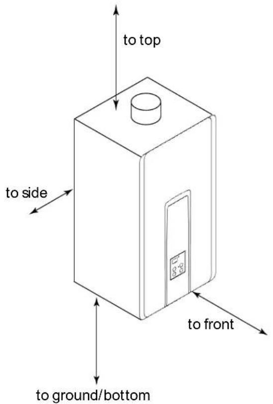
to top to side to front to ground/bottomOutdoor models: RL75e, RL94e
| to Combustibles inches (mm) | to Non-Combustibles inches (mm) | |
| Top of Heater | 12 (305) | 2 (51) |
| Back of Heater | 0 (zero) | 0 (zero) |
| Front (Panel) | 24 (610) | 0 (zero) |
| Front (Exhaust) | 24 (610) | 24 (610) |
| Sides of Heater | 6 (152) | 1/8 (3.2) |
| Ground/Bottom | 12 (305) | 2 (51) |
The clearance for servicing is 24 inches in front of the water heater.
Maximum vent length (indoor models only)
- Determine the number of 90 degree elbows in the vent system. (Two 45 degree elbows count as one 90 degree elbow.)
- Refer to the table to find the maximum vent length based on the number of elbows.
| Number of 90° Elbows | Maximum vent length |
| 0 41 ft (12.5 m) 1 | |
| 1 35 ft (10.7 m) 2 | |
| 2 29 ft (8.8 m) 3 | |
| 3 23 ft (7.0 m) 4 | |
| 4 17 ft (5.2 m) 4 | |
| 5 11 ft (3.4 m) 4 | |
| 6 5 ft (1.5 m) 4 |
- Adjust switch No. 1 in the SW1 DIP switch (tan switches) if required by the applicable note.
① If the length is greater than 21 ft (6.4 m) then move switch No. 1 (SW1) to OFF.
② If the length is greater than 15 ft (4.6 m) then move switch No. 1 (SW1) to OFF.
③ If the length is greater than 9 ft (2.7 m) then move switch No. 1 (SW1) to OFF.
④ Move switch No. 1 (SW1) to OFF.
Example: If you have one elbow then your maximum vent length is 35 feet (10.7 m). If your actual length is greater than 15 ft (4.6 m) then move switch no. 1 (SW1) to OFF.
NOTICE
If you have a longer vent length (see number 3 regarding max. vent length), switch No. 1 is required to be in the OFF position. This ensures the water heater will run properly. Blocked flue diagnostic codes and shutdowns may result if switch No. 1 is not in the correct position.
Freeze Protection
Make sure that in case of freezing weather that the water heater and its water lines are protected to prevent freezing. Damage due to freezing is not covered by the warranty.
With electrical power and gas supplied, the water heater will not freeze when the outside air temperature is as cold as -22^ (-30°C) for indoor models or is as cold as -4^ (-20°C) for outdoor models, when protected from direct wind exposure. Because of the “wind-chill” effect, any wind or circulation of the air on the unit will reduce its ability to protect itself from freezing.
In the event of a power failure and/or gas interruption at temperatures below freezing the water heater should be drained of all water to prevent freezing damage. In addition, drain the condensate trap and drain line.
Loss of freeze protection may result in water damage from a burst heat exchanger or water lines.
The unit may be drained manually. However, it is highly recommended to:
- drain down solenoid valves be purchased and installed that will automatically drain the unit if power is lost. These are available in a kit, 104000059. (The condensate trap is not affected by the auto drain down solenoid valves and will have to be manually drained.)
- a surge protector with terminals be purchased and installed which allows the solenoid valves to operate if the unit is disabled due to a diagnostic code. This is available as 104000057.
In addition, the solenoid valves should be connected electrically to a surge protector with terminals. This allows the solenoid valves to operate if the water heater is disabled due to a diagnostic code.
The freeze protection features will not prevent the external piping from freezing. It is recommended that hot and cold water pipes be insulated. Pipe cover enclosures may be packed with insulation for added freeze protection.
Checklist to Determine Installation Location
☐ The water heater is not exposed to corrosive compounds in the air.
☐ The water heater location complies with the clearances.
☐ For indoor models, the planned venting will not exceed the maximum length for the number of elbows used.
☐ The planned venting termination/air intake location meets the clearances.
□ Indoor air is not being used for combustion.
☐ The water supply does not contain chemicals or exceed total hardness that will damage the heat exchanger.
☐ A standard 3 prong 120 VAC, 60 Hz properly grounded wall outlet (for indoor models) or other 120 VAC, 60 Hz source is available.
☐ The installation must conform with local codes or, in the absence of local codes, with the National Fuel Gas Code, ANSI Z223.1/NFPA 54, or the Natural Gas and Propane Installation Code, CSA B149.1. If installed in a manufactured home, the installation must conform with the Manufactured Home Construction and Safety Standard, Title 24 CFR, Part 3280 and/or CAN/SCA Z240 MH Series, Mobile Homes.
☐ Leave the entire manual taped to the water heater (indoor models), temperature controller (outdoor models), or give the entire manual directly to the consumer.
Mount to Wall
text_image
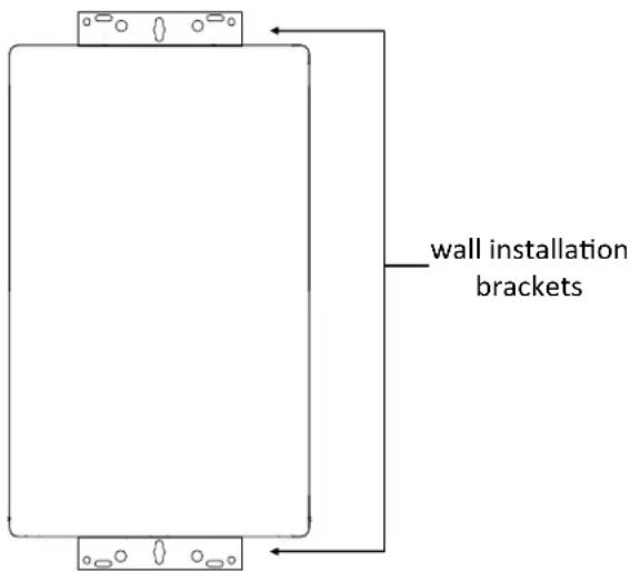
wall installation brackets- Identify the installation location and confirm that the installation will meet all required clearances.
- Securely attach the water heater to the wall using any of the holes in the wall installation brackets which are at the top and bottom of the water heater. Ensure that the attachment strength is sufficient to support the weight. Refer to the weight of the water heater in the Specifications section. Use a leveling tool to ensure that the water heater is level. Proper operation requires that the water heater be level.
NOTE: The water heater must be installed in an upright position. Do not install upside down or on its side.
Remove the Front Panel
Slide the plastic trim pieces on each side of the water heater to expose the screws.
Remove the 4 screws and pull off the front panel.
Installation of venting (indoor models only)
Install the correct venting for your model according to the venting manufacturer's instructions and the guidelines below.
Refer to the manufacturer's technical literature for specific part numbers and instructions.
| Manufacturer | Listed and Tested Vent Products for RL75i, RL94i, and RLX94i | Telephone Fax | Contact | |
| Ubbink | Rolux Vent System | 800-621-9419 | 678-829-1666 | www.rinnai.us |
| Heat-Fab | Saf-T Vent SC system | 800-772-0739 | 413-863-4803 | custsvc@heat-fab.com, www.heatfab.com |
| Metal-Fab | Corr/Guard Vent/Air Intake System | 800-835-2830 | 316-943-2717 | info@mtlfab.com, www.metal-fabinc.com |
Venting Guidelines
DO NOT
- Do not use PVC, CPVC, ABS or galvanized material to vent this appliance.
- Do not combine vent components from different manufacturers.
• Vent diameter must not be reduced. - Do not connect the venting system with an existing vent or chimney.
- Do not common vent with the vent pipe of any other water heater or appliance.
MUST DO
- This water heater is a direct vent water heater and therefore is certified and listed with the vent system. You must use vent components that are certified and listed with the water heater model.
- The vent system must vent directly to the outside of the building and use outside air for combustion.
- Avoid dips or sags in horizontal vent runs by installing supports per the vent manufacturer's instructions.
- Support horizontal vent runs every four feet and all vertical vent runs every six feet or in accordance with local codes.
- Venting should be as direct as possible with a minimum number of pipe fittings.
- Vent connections must be firmly pressed together so that the gaskets form an air tight seal.
- The vent piece connected to the water heater must be secured with one self-tapping screw.
INFORMATION
- Refer to the instructions of the vent system manufacturer for component assembly instructions.
- If the vent system is to be enclosed, it is suggested that the design of the enclosure shall permit inspection of the vent system. The design of such enclosure shall be deemed acceptable by the installer or the local inspector.
NOTICE
If it becomes necessary to access an enclosed vent system for service or repairs, Rinnai is not responsible for any costs or difficulties in accessing the vent system. The warranty does not cover obtaining access to a vent system in an enclosed environment.
Flue Installation (indoor models only)
Install the venting termination according to the diagrams and instructions below.
Horizontal Termination without using the Condensate Collector

WARNING
If the condensate collector is not used, the drain pipe must be capped to prevent exhaust gases and condensate from entering the building. The cap is supplied on the appliance. In such an instance slope the venting 1/4" per foot away from appliance according to vent manufacturer's installation instructions.

natural_image
Technical line drawing of a mechanical assembly with no visible text or symbols
text_image
Must from ance. ray * The condensate collector must be used in horizontal terminations if a vertical rise in the vent system exceeds 5ft. Maximum Height * 5 feet (1.52 m) Regions of cold climate will create m condensate in the vent system. The condensate collector should be used cold climates. If more than one elbow is used in the vertical section the condensate colle must be used.Horizontal Termination using Condensate Collector
Slope the venting 1/4" per foot toward the appliance according to the vent manufacturers installation instructions Dispose of condensate per local codes.

text_image
ppliance according to the vent facturers installation instructions. se of condensate per local codes. Condensate Trap 3 in (75 mm) minimumVertical Termination
(condensate collector must be used in all installations)
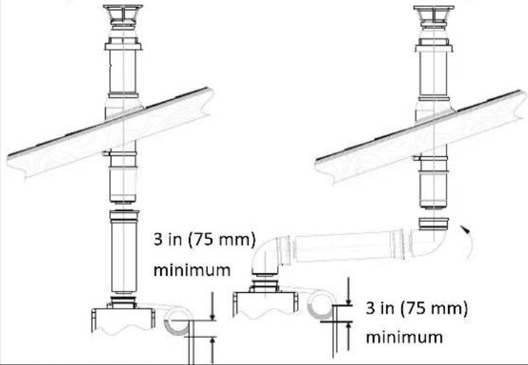
text_image
3 in (75 mm) minimum 3 in (75 mm) minimum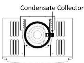
text_image
Condensate Collector
text_image
BracketTo adjust the condensate collector position or to replace the female vent top with a male vent top:
- Loosen the 4 screws at the rear bracket
- Slide the bracket away from the female vent top.
- Remove the 4 screws attaching the female vent top to the water heater.
- Lift up the female vent top and reposition as desired (or replace with a male vent top).
- Install the 4 screws at the vent top and tighten the 4 screws at the bracket.
Secure the first vent component to the water heater with one self-tapping screw at the hole located above the condensate collector.
Condensate (indoor models only)
Condensate can form in the vent of high efficiency direct vent appliances. Without proper drainage, condensate will damage the heat exchanger.
To prevent condensate damage, follow these instructions.
DO NOT
- Do not allow condensate to enter the water heater.
- Do not connect the condensate drain pipe directly to the rain sewer.
- Do not connect the condensate drain line with an air conditioning evaporator coil drain or.
- Do not connect the condensate drain line to the pressure relief valve/line of the appliance.
MUST DO
- Use only venting that is approved and identified as acceptable for your particular model.
- For vertical terminations, install a condensate drain and trap as close as possible to the appliance.
- Slope the venting toward the appliance according to the vent manufacturer's installation instructions.
- All condensate must drain and be disposed of according to local codes.
- Use only corrosion resistant materials for the condensate drain lines such as PVC pipe or plastic hose.
- The condensate drain pipe (along its entire length) must be at least the same diameter as the drain line, (5/8 inch NPT).
- The end of the condensate drain pipe should be open to the atmosphere. The end should not be under water or other substances.
- To minimize freezing of the condensate, run the condensate drain line through an interior wall or between insulation and an interior wall.
- The condensate collector should be used for all combination domestic/hydronic heating applications.
INFORMATION
- A condensate trap is available, P/N 222053.
- Regions of cold climate will create more condensate in the vent system. The condensate collector should be used in cold climates.
- The condensate drain pipe should be as short as possible and have a downward pitch.
Checklist for Venting and Condensate (indoor models only)
☐ Verify proper clearances around the vent terminations and air intakes.
□ Ensure you have used the correct venting products for the model installed and that you have completely followed the venting manufacturer's installation instructions and these installation instructions.
☐ Verify that the vent pipe has a downward slope or grade to the outside of 1/4 inch per foot (1.2°) OR if the vent pipe is sloped toward the water heater (as some local codes require), that a condensate collector is installed to allow condensation to drain away from the water heater to a proper drain source.
☐ Verify that condensate will not be allowed to drain back into the water heater.
☐ Verify that the vent system does not exceed the maximum length for the number of elbows used.
Installation of Plumbing
Pressure Relief Valve Requirements
Install the pressure relief valve according to these instructions.
An approved pressure relief valve is required by the American National Standard (ANSI Z21.10.3) for all water heating systems and shall be accessible for servicing.
DO NOT
- Do not plug the relief valve and do not install any reducing fittings or other restrictions in the relief line. The relief line should allow for complete drainage of the valve and the line.
- Do not place any other type valve or shutoff device between the relief valve and the water heater.
MUST DO
- The relief valve must comply with the standard for Relief Valves and Automatic Gas Shutoff Devices for Hot Water Supply Systems ANSI Z21.22 and /or the standard Temperature, Pressure, Temperature and Pressure Relief Valves and Vacuum Relief Valves, CAN1-4.4.
- The relief valve must be rated up to 150 psi and to at least the maximum BTU/hr of the appliance.
- The discharge from the pressure relief valve should be piped to the ground or into a drain system per local codes.
- The pressure relief valve must be manually operated once a year to check for correct operation.

WARNING
Water discharged from the pressure relief valve could cause severe burns instantly or death from scalds.
- The relief valve should be added to the hot water outlet line and near the hot water outlet according to the manufacturer's instructions. DO NOT place any other type valve or shut off device between the relief valve and the water heater.
INFORMATION
- If a relief valve discharges periodically, this may be due to thermal expansion in a closed water supply system. Contact the water supplier or local plumbing inspector on how to correct this situation. Do not plug the relief valve.
- The American National Standard (ANSI Z21.10.3) does not require a combination temperature and pressure relief valve for this appliance. However, local codes may require a combination temperature and pressure relief valve.
Isolation Valves
Isolation valves are included with this water heater. Rinnai strongly recommends the installation of isolation valves on the cold and hot water lines because they provide the ability to isolate the water heater from the structure's plumbing and allow quick access to flush the heat exchanger. Flushing the heat exchanger regularly is required as part of the proper maintenance for this water heater.
Piping Requirements
A manual water control valve must be placed in the water inlet connection to the water heater before it is connected to the water line. Unions may be used on both the hot and cold water lines for future servicing and disconnection of the unit.
DO NOT
- Do not introduce toxic chemicals such as those used for boiler water treatment to the potable water used for space heating.
MUST DO
- The piping (including soldering materials) and components connected to this appliance must be approved for use in potable water systems.
- Purge the water line to remove all debris and air. Debris will damage the water heater.
- If the appliance will be used as a potable water source, it must not be connected to a system that was previously used with a nonpotable water heating appliance.
- Ensure that the water filter on the water heater is clean and installed.
Isolation Valves and Pressure Relief Valve
The isolation valves provide the ability to isolate the water heater from the structure's plumbing and allow quick access to flush the heat exchanger. Check with local codes to determine if a pressure and temperature relief valve is required. The included valves meet American National Standard (ANSI Z21.10.3) / Canadian Standard (CSA 4.3) and are ANSI/NSF 61 approved for potable water.
Isolation Valves Installation Instructions:
-
Wrap the threaded end of the approved pressure relief valve with a minimum of 5 wraps of Teflon® tape.
-
Install the pressure relief valve to the 3/4" threaded port on the HOT (RED) water service valve (will be adjacent to or above the cut off, never below). See Pressure Relief Valve Section for proper installation requirements.
-
Position the Hot Isolation Valve (Red) below the Hot Outlet side of the water heater.
-
Hand tighten the Swivel Nut of the Hot Isolation Valve (Red) to the Hot Outlet side of the water heater.
-
Rotate the Drain Valve to an accessible position. With a wrench, tighten the Swivel Nut to the water heater.
-
Repeat steps 3-5 for the Cold Isolation Valve (Blue).
-
Connect the Cold Isolation Valve (Blue) to the Cold Water Supply Line.
-
Connect the Hot Isolation Valve (Red) to the Hot Water Supply Line.
-
Ensure that both Drain Valves are in the closed position before turning on water supply.

text_image
Hot Outlet Cold Inlet Swivel Nut (Integrated Gasket) Drain Valve Pressure Relief Valve Hot Isolation Valve (Red) Cold Isolation Valve (Blue)Pressure Relief Valve (PRV) Installation Instructions:
The PRV must be connected to the 3/4" threaded port on the HOT (RED) water service valve (will be adjacent to or above the shut off, never below). Installation must maintain a 34 " port size with no shut off valve or line restriction in-between the appliance and the PRV. The discharge line from the PRV should pitch downward and terminate 6" above drains where discharge will be clearly visible. The discharge end of the line shall be plain (unthreaded) and a minimum of 34 " in diameter. The discharge line material must be suitable for water at least 180° Fahrenheit. No valve of any type may be installed in the discharge line of the pressure relief valve.
Pressure Relief Valve Maintenance:
For proper care of this approved pressure relief valve, it is recommended that the valve is manually operated once a year. In doing so, it will be necessary to take precautions with regard to the discharge of potentially scalding hot water under pressure. Ensure discharge water has a safe place to flow. Contact with your body or other property may cause damage or harm.
Please note that only the PRV in this package is certified by CSA International as an approved item.
Piping Diagram for Basic Installation
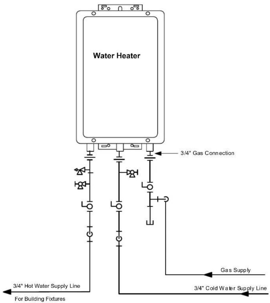
text_image
Water Heater 3/4" Gas Connection 3/4" Hot Water Supply Line For Building Fixtures Gas Supply 3/4" Cold Water Supply Line| KEY | This is not an engineered drawing. It is intended only as a guide and not as a replacement for professionally engineered project drawings. This drawing is not intended to describe a complete system. It is up to the contractor/engineer to determine the necessary components and configuration of the particular system being installed. This drawing does not imply compliance with local building code requirements. It is the responsibility of the contractor/engineer to ensure installation is in accordance with all local building codes. Confer with local building officials before installation. | |||
| [DS2C] | 3/4" Ball Valve | [CSBA] | Pressure Regulator | |
| — | 3/4" Union | Circulating Pump | ||
 | Check Valve | [WAVZ] | Boiler Drain Valve | |
 | Pressure Relief Valve | [KZSX] | Solenoid Valve | |
Connect Water Heater to Water Supply
Water connections to the tankless water heater should follow all state and local plumbing codes.
If this is a standard installation, refer to the Piping Diagram for Basic Installation.
- Plumb water supply to the tankless water heater on the 3/4" MNPT connection at the bottom of the unit marked "Water Inlet", which is the cold water supply.
- Plumb the building hot water supply to the 3/4" MSPT connection marked "Water Outlet", which is the hot water supply.
If a pipe cover will be installed, make sure water lines to the water heater fit.
Checklist for Plumbing
☐ Purge the water line of all debris and air by closing the hot isolation valve and opening the cold isolation valve and its drain. Debris will damage the water heater. Use a bucket or hose if necessary.
☐ Ensure that hot and cold water lines are not crossed to the unit and are leak free.
☐ Ensure that a pressure relief valve is installed with a rating that exceeds the BTU input of the water heater model. Refer to the rating plate on the side of the water heater for BTU input.
☐ Clean the inlet water filter by closing the cold and hot water inlet isolation (shut-off) valves. Put a bucket under the filter at the bottom of the water heater to catch any water that is contained inside the unit. Unscrew the water filter. Rinse the filter to remove any debris. Install the filter and open the isolation valves.
☐ Check for proper water pressure to the water heater. Minimum/Maximum water pressure is 20-150 psi. Rinnai recommends 30-80 psi for maximum performance.
Installation of Gas Supply
WARNING
- A licensed professional must install the gas supply.
- Turn off 120v power supply.
- Turn off the gas.
- Gas is flammable. Do not smoke or provide other ignition sources while working with gas.
- Do not turn on the water heater or gas until all fumes are gone.
General Instructions
MUST DO
- A manual gas control valve must be placed in the gas supply line to the water heater. A union can be used on the connection above the shut off valve for the future servicing or disconnection of the unit.
- Check the type of gas and the gas inlet pressure before connecting the water heater. If the water heater is not of the gas type that the building is supplied with, DO NOT connect the water heater. Contact the dealer for the proper unit to match the gas type.
- Check the gas supply pressure immediately upstream at a location provided by the gas company. Supplied gas pressure must be within the limits shown in the Specifications section of this manual with all gas appliances operating.
- Before placing the appliance in operation, all joints including the heater must be checked for gas tightness by means of leak detector solution, soap and water, or an equivalent nonflammable solution, as applicable. (Since some leak test solutions, including soap and water, may cause corrosion or stress cracking, the piping shall be rinsed with water after testing, unless it has been determined that the leak test solution is non-corrosive.)
-
Use approved connectors to connect the unit to the gas line. Purge the gas line of any debris before connection to the water heater.
-
Any compound used on the threaded joint of the gas piping shall be a type that resists the action of liquefied petroleum gas (propane / LPG).
- The gas supply line shall be gas tight, sized, and so installed as to provide a supply of gas sufficient to meet the maximum demand of the heater and all other gas consuming appliances at the location without loss of pressure.
INFORMATION
- Refer to an approved pipe sizing chart if in doubt about the size of the gas line.
Size the gas pipe
The gas supply must be capable of handling the entire gas load required at the location. Gas line sizing is based on gas type, the pressure drop in the system, the gas pressure supplied, and gas line type. For gas pipe sizing in the United States, refer to the National Fuel Gas Code, NFPA 54. The below information is provided as an example. The appropriate table from the applicable code must be used.
-
For some tables, you will need to determine the cubic feet per hour of gas required by dividing the gas input by the heating value of the gas (available from the local gas company). The gas input needs to include all gas products at the location and the maximum BTU usage at full load when all gas products are in use.
-
Use the table for your gas type and pipe type to
$$ \begin{array}{l l} \text {Cubic Feet} & \text {Gas Input of all gas products (BTU / HR)} \ \text {per Hour =} & \frac {}{\text {Heating Value of Gas (BTU / FT} ^ {3})} \ (\text {CFH}) & \end{array} $$
find the pipe size required. The pipe size must be able to provide the required cubic feet per hour of gas or the required BTU/hour.
Example:
The heating value of natural gas for your location is 1000 BTU/FT ^3 . The gas input of the RL94i is 199,000 BTU/HR. Additional appliances at the location require 65,000 BTU/hr. Therefore the cubic feet per hour = (199,000 + 65,000) / 1000 = 264 FT ^3 /HR. If the pipe length is 10 feet then the 3/4 inch pipe size is capable of supplying 264 FT ^3 /HR of natural gas.
Pipe Sizing Table - Natural Gas
Schedule 40 Metallic Pipe
Inlet Pressure: less than 2 psi (55 inches W.C.)
Pressure Drop: 0.3 inches W.C.
Specific Gravity: 0.60
cubic feet per hour
| Length | Pipe Size (inches) | |||
| 3/4 | 1 | 1 1/4 | 1 1/2 | |
| 10 | 273 | 514 | 1060 | 1580 |
| 20 | 188 | 353 | 726 | 1090 |
| 30 | 151 | 284 | 583 | 873 |
| 40 | 129 | 243 | 499 | 747 |
| 50 | 114 | 215 | 442 | 662 |
| 60 | 104 | 195 | 400 | 600 |
| 70 | 95 | 179 | 368 | 552 |
| 80 | 89 | 167 | 343 | 514 |
| 90 | 83 | 157 | 322 | 482 |
| 100 | 79 | 148 | 304 | 455 |
Pipe Sizing Table - Propane Gas
Schedule 40 Metallic Pipe
Inlet Pressure: 11.0 inches W.C.
Pressure Drop: 0.5 inches W.C.
Specific Gravity: 1.50
Capacity in Thousands of BTU per Hour
| Length | Pipe Size (inches) | |||
| 1/2 | 3/4 | 1 | 1 1/4 | |
| 10 | 291 | 608 | 1150 | 2350 |
| 20 | 200 | 418 | 787 | 1620 |
| 30 | 160 | 336 | 632 | 1300 |
| 40 | 137 | 287 | 541 | 1110 |
| 50 | 122 | 255 | 480 | 985 |
| 60 | 110 | 231 | 434 | 892 |
| 80 | 101 | 212 | 400 | 821 |
| 100 | 94 | 197 | 372 | 763 |
Connect Electricity

WARNING
Do not use an extension cord or an adapter plug with this appliance.
The water heater must be electrically grounded in accordance with local codes and ordinances or, in the absence of local codes, in accordance with the National Electrical Code, ANSI/NFPA No. 70.
Indoor water heaters are equipped with a three-prong (grounding) plug for your protection against shock hazard and should be plugged directly into a properly grounded three-prong receptacle. Do not cut or remove the grounding terminal from this plug.
Do not rely on the gas or water piping to ground the water heater. A screw is provided in the junction box for the grounding connection.
The water heater requires 120 VAC, 60 Hz power from a properly grounded circuit.
If using the 5 foot long power cord, plug it into a standard 3 prong 120 VAC, 60 Hz properly grounded wall outlet.
On outdoor models, a disconnect switch must be provided and installed for the incoming 120 VAC power. It should be a type that is suitable for outdoor use. Check the National Electrical Code, ANSI/NFPA 70 and your local codes for a proper switch type to use in your area.
The wiring diagram is located on the Technical Sheet attached to the inside of the front cover.
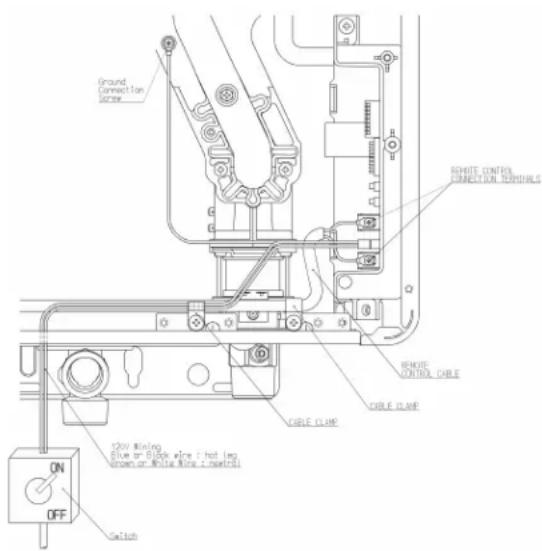
text_image
Ground Connection Screw WHITE CONTROL FUNCTION TERMINALS WHITE CONTROL CABLE CABLE CUBE 12kV Wiring Blue or Black wire ( hot leg brown or White Wire ( next(s) ) ON OFF SwitchVC Series Manual 21
Adjustment for High Altitude Installations
On the SW1 DIP switch (tan switches), set switches 2 and 3 to the values shown in table below for your altitude. The default setting for the appliance is 0-2000 ft (0-610 m) with switches No. 2 and No. 3 in the OFF position.
When the DIP switch is adjusted, it is not necessary to adjust the gas pressure setting for high altitude.
| Altitude | SW1SwitchNo. 2 | SW1SwitchNo. 3 |
| 0-2000 ft (0-610 m) | OFF | OFF |
| 2001-5200 ft (610-1585 m) | OFF | ON |
| 5201-7700 ft (1585-2347 m) | ON | OFF |
| 7701-10200 ft (2347-3109 m) | ON | ON |
Adjustment for Vent Length (Indoor models only)
Adjust switch No. 1 in the SW1 DIP switch (tan switches) if required. Refer to the section "Maximum vent length".
Checklist for Gas and Electricity
☐ A manual gas control valve is placed in the gas line to the water heater.
☐ Check the gas lines and connections for leaks.
☐ Confirm that the gas inlet pressure is within limits.
☐ Confirm that the water heater is rated for the gas type supplied.
☐ Confirm that the electricity is supplied from 120 VAC, 60 Hz power source and is in a properly grounded circuit.
☐ Confirm an extension cord or an adapter plug has not been used with the water heater.
☐ For indoor models verify that switch No. 1 in the SW1 DIP switch (tan switches) has been adjusted for vent length if necessary. Refer to the section on Maximum Vent Length.
Installation of Temperature Controller

WARNING
Turn the power off. Do not attempt to connect the temperature controller(s) with the power on. Although the controller is a low voltage device, there is 120 volt potential next to the temperature controller connections inside the unit.
Do not connect the temperature controller to the 120VAC terminals provided for the optional solenoid drain valves.
Indoor models have their controller built into the front panel. Additional controllers can be installed.
Controller Location
- The controller should be out of reach of small children.
- Avoid locations where the controller may become hot (near an oven or radiant heater).
- Avoid locations in direct sunlight. The digital display may be difficult to read in direct sunlight.
- Avoid locations where the temperature controller could be splashed with liquids.
- Do not install in locations where the controller can be adjusted by the public.
Cable Lengths and Sizes
The cable for the temperature controller should be a non-polarized two-core cable with a minimum gauge of 22 AWG. The maximum cable length from each controller to the water heater depends on the total number of wired controllers connected to the water heater.
| Number of Wired Controllers | Maximum Cable Length for each Controller to Water Heater |
| 1 328 ft (100 m) | |
| 2 164 ft (50 m) | |
| 3 or 4* 65 ft (20 m) |
* Only 3 additional controllers can be wired to the indoor water heater.
Configurations
A maximum of 4 temperature controllers can be installed for a water heater or bank of water heaters. This includes the controller built into an indoor water heater. Controllers can only be wired in parallel. Controllers cannot be wired in series.

flowchart
graph TD
    A["Rinnai Water Heater"] --> B["Wire controllers in parallel"]
    B --> C["Controller 1"]
    B --> D["Controller 2"]
    B --> E["Controller 3"]
    C --> F["Maximum 4 Controllers"]
    D --> F
    E --> F
The 4 temperature controllers can consist of multiple MC-91-2 or MCC-91-2 but only one BC-100V and only one MC-100V.
(MC-91-1 should not be installed on a unit that already has an MC-91-2 connected)
The clock function on the BC-100V will only be available if an MC-100V is also connected.
If 4 MC-91-2's are installed, simultaneously press the Priority and On/Off buttons on the fourth controller until a beep sounds.
Mounting the controller
- Make three holes in the wall as shown.
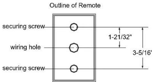
text_image
Outline of Remote securing screw wiring hole securing screw 1-21/32" 3-5/16'-
Run the cable between the controller and the water heater or the controller and another controller.
-
Remove the face plate from the temperature controller using a screwdriver.
-
Connect the cable to the temperature controller.
-
Mount the controller to the wall using the holes drilled in step 1.
-
Disconnect the power from the water heater.
-
Remove the plastic cover from the PCB and electrical connections.
-
Thread the cable through the access hole at the base of the unit and connect the wires to the controller terminals on the right hand side bottom of the PCB.
-
Secure the controller cable using the clamp provided.
-
Replace plastic cover over PCB and then replace the cover of the water heater.

text_image
REMOTE CONTROL CONNECTION SPANDS CABLE CUBE REMOTE CONTROL CUBEVC Series Manual 23
Final Checklist
☐ The water heater is not subject to corrosive compounds in the air.
☐ The water supply does not contain chemicals or exceed total hardness that will damage the heat exchanger.
☐ Clearances from the water heater unit are met.
☐ Clearances from the vent termination / air intake are met.
For indoor models, ensure you have used the correct venting products for the model installed and that you have completely followed the venting manufacturer's installation instructions and these installation instructions.
☐ For indoor models, verify that the vent system does not exceed the maximum length for the number of elbows used.
☐ For indoor models verify that switch No. 1 in the SW1 DIP switch (tan switches) has been adjusted for vent length if necessary. Refer to the section on Maximum Vent Length.
☐ For indoor models, verify that the vent pipe has a downward slope or grade to the outside of 1/4 inch per foot (1.2°) OR, if the vent pipe is sloped toward the water heater (as some local codes require), that a condensate collector is installed to allow condensation to drain away from the water heater to a proper drain source.
☐ For indoor models, verify that condensate will not be allowed to drain back into the water heater.
☐ Purge the water line of all debris and air by closing the hot isolation valve and opening the cold isolation valve and its drain. Debris will damage the water heater. Use a bucket or hose if necessary.
☐ Ensure that hot and cold water lines are not crossed to the unit and are leak free.
☐ Clean the inlet water filter by closing the cold and hot water inlet isolation (shut-off) valves. Put a bucket under the filter at the bottom of the water heater to catch any water that is contained inside the unit. Unscrew the water filter. Rinse the filter to remove any debris. Install the filter and open the isolation valves.
☐ Ensure that a pressure relief valve is installed with a rating that exceeds the BTU input of the water heater model. Refer to the rating plate on the side of the water heater for BTU input.
☐ A manual gas control valve has been placed in the gas line to the water heater.
□ Check the gas lines and connections for leaks.
☐ Confirm that the gas inlet pressure is within limits.
☐ Confirm that the water heater is rated for the gas type supplied.
☐ Confirm that the electricity is supplied from a 120 VAC, 60 Hz power source, is in a properly grounded circuit, and turned on.
□ Verify the temperature controller is functioning properly.
☐ Verify that switches No. 2 and No. 3 in the SW1 DIP switch (tan switches) is set correctly for your altitude.
☐ Verify the system is functioning correctly by connecting your manometer to the gas pressure test port on the water heater. Operate all gas appliances in the home or facility at high fire. The inlet gas pressure at the water heater must not drop below that listed on the rating plate.
☐ DO NOT introduce toxic chemicals such as those used for boiler water treatment to the potable water used for space heating.
☐ If the water heater is not needed for immediate use, then drain the water from the heat exchanger.
□ Install the front panel.
□ Explain to the customer the importance of not blocking the vent termination or air intake.
☐ Explain to the customer the operation of the water heater, safety guidelines, maintenance, and warranty.
☐ The installation must conform with local codes or, in the absence of local codes, with the National Fuel Gas Code, ANSI Z223.1/NFPA 54, or the Natural Gas and Propane Installation Code, CSA B149.1. If installed in a manufactured home, the installation must conform with the Manufactured Home Construction and Safety Standard, Title 24 CFR, Part 3280 and/or CAN/SCA Z240 MH Series, Mobile Homes.
☐ Inform the consumer if the isolation valves are not installed or if a water softening system is not installed.
□ Leave the entire manual taped to the water heater (indoor models), temperature controller (outdoor models), or give the entire manual directly to the consumer.
Technical Data
Specifications
| RL75i | RLX94i | RL94i | RL75e | RL94e | ||
| Minimum Gas Consumption Btu/h 10,300 | ||||||
| Maximum Gas Consumption Btu/h | 180,000 | 192,000 | 199,000 | 180,000 | 199,000 | |
| Hot water capacity (Min - Max) * | 0.26 - 7.5 GPM(1.0 - 28.5 L/min) | 0.26 - 9.8 GPM(1.0 - 37.0 L/min) | 0.26 - 9.8 GPM(1.0 - 37.0 L/min) | 0.26 - 7.5 GPM(1.0 - 28.5 L/min) | 0.26 - 9.8 GPM(1.0 - 37.0 L/min) | |
| Temperature Setting (no controller) | 120°F (49°C) or 140°F (60°C) | |||||
| Maximum Temp Setting (residential) | Selectable at 120°F (49°C) or at 140°F (60°C) | |||||
| Maximum Temp Setting(MCC-91 controller) | 160°F (71°C) | 185°F (85°C) | 185°F (85°C) | 160°F (71°C) | 185°F (85°C) | |
| Minimum Temperature Setting | 98°F (37°C) | |||||
| Weight | 45.6 lb (20.7 kg) | 46.3 lb (21.0 kg) | 46.3 lb (21.0 kg) | 43.6 lb (19.8 kg) | 44.3 lb (20.1 kg) | |
| Noise level | 49 dB (excluding start up or shutdown) | |||||
| Electrical Data | Normal | 76 W | 97 W | 97 W | 57 W | 65 W |
| Standby | 2 W | |||||
| Anti-frost Protection | 120 W | 104 W | ||||
| Max Current | Without recirculation pump: 4 AWith recirculation pump: 8 A (exact value depends on the pump) | |||||
| Fuse | 10 A | |||||
| By-Pass Control | Fixed | Electronic | Electronic | Fixed | Electronic | |
| Gas SupplyPressure | Natural Gas | 4.0 - 10.5 inch W.C. | ||||
| Propane | 8.0 - 13.5 inch W.C. | |||||
| Type of Appliance | Direct Vent, Tankless, Temperature controlled continuous flow gas hot water system | |||||
| Connections | Gas Supply: 3/4" MNPT, Cold Water Inlet: 3/4" MNPT, Hot Water Outlet: 3/4" MNPT | |||||
| Ignition System | Direct Electronic Ignition | |||||
| Electric Connections | Appliance: AC 120 Volts, 60Hz.Temperature Controller: DC 12 Volts (Digital) | |||||
| Water Temperature Control | Simulation Feedforward and Feedback | |||||
| Water Supply Pressure | Minimum Water Pressure: 20 PSI (Recommended 30-80 PSI for maximum performance) | |||||
| Maximum Water Supply Pressure | 150 PSI | |||||
| Temperature Control Cable | Non-Polarized Two Core Cable (Minimum 22 AWG) | |||||
| Certified for installation in manufactured (mobile) homes | Yes | |||||
| Complies with South Coast Air Quality Management District 14 ng/J or 20 ppm NOx emission levels | Yes | Yes | No | Yes | Yes | |
* Minimum flow may vary slightly depending on the temperature setting and the inlet water temperature. Minimum activation flow is 0.4 GPM (1.5 L/min).
Our products are continually being updated and improved; therefore, specifications are subject to change without prior notice. The maximum inlet gas pressure must not exceed the value specified by the manufacturer. The minimum value listed is for the purpose of input adjustment.
Dimensions
Inches (millimeters)
RL75i, RL94i, RLX94i
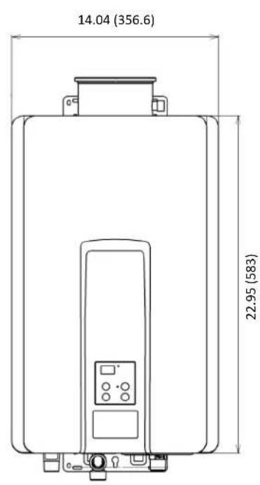
text_image
14.04 (356.6) 22.95 (583)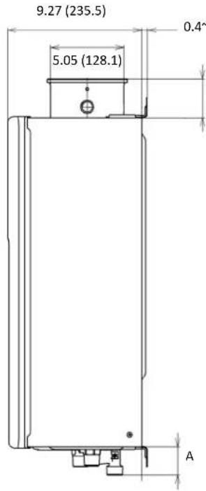
text_image
9.27 (235.5) 5.05 (128.1) 0.4^ A
text_image
.8(10~45) Variable 2.6/ (6/8) COLD WATER INLET GAS CONNECTION HOT WATER OUTLET B C E D F G| DIMENSION | Inches (mm) | DIMENSION | Inches (mm) |
| A (GAS) | 1.31 (33.2) | D | 4.33 (110) |
| A (COLD) | 1.93 (49) | E | 2.89 (73.3) |
| A (HOT) | 1.35 (34.4) | F | 1.85 (47) |
| B | 4.21 (106.9) | G | 3.44 (87.3) |
| C | 1.17 (29.8) |
RL75e, RL94e

text_image
14.04 (356.6) 8.90 (226) 2.23 (56.6) 1.14 (29) 22.95 (583) 0.28 (7.2) 9.27 (235.5) 0.59 (15) A HOT COLU
text_image
GAS CONNECTION B HOT WATER OUTLET C E D F G COLD WATER INLET| DIMENSION | Inches (mm) | DIMENSION | Inches (mm) |
| A (GAS) | 1.31 (33.2) | D | 4.33 (110) |
| A (COLD) | 1.93 (49) | E | 2.91 (73.8) |
| A (HOT) | 1.35 (34.4) | F | 1.61 (40.8) |
| B | 3.96 (100.7) | G | 2.87 (73) |
| C | 1.17 (29.8) |
Pressure Drop Curve

line
| Water Flow (gpm) | Pressure Loss (psi) | | ---------------- | ------------------- | | 01234567891011 | 0.00 | | | 5.00 | | | 10.00 | | | 15.00 | | | 20.00 | | | 25.00 | | | 30.00 | | | 35.00 | | | 40.00 | | | 45.00 | | | 50.00 | | | 55.00 | | | 60.00 | | | 65.00 | | | 70.00 | | | 75.00 | | | 80.00 | | | 85.00 | | | 90.00 | | | 95.00 | | | 100.00 |Water Flow Curve
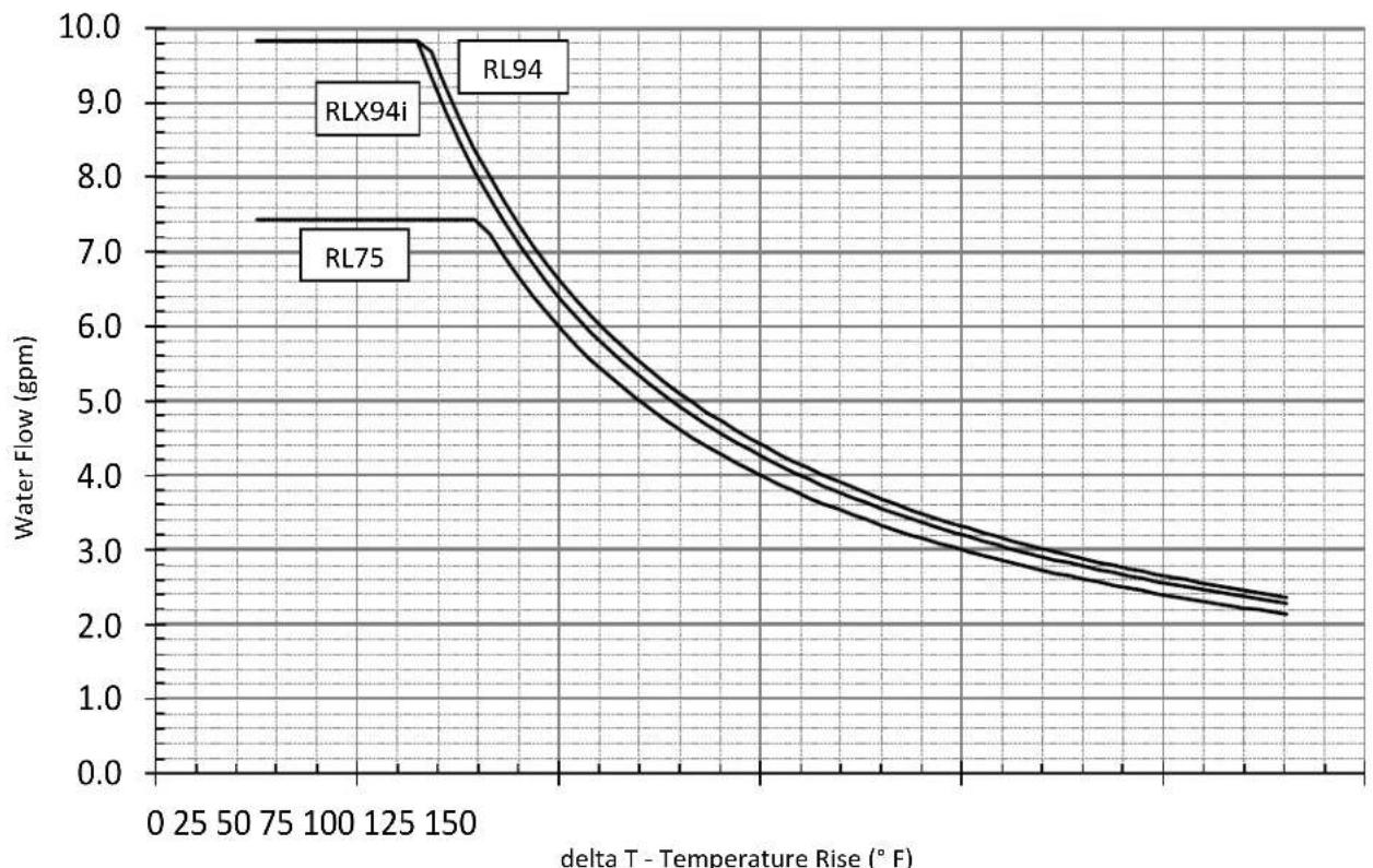
line
| delta T - Temperature Rise (° F) | RL94 (gpm) | RLX94i (gpm) | RL75 (gpm) | | -------------------------------- | ---------- | ------------ | ---------- | | 0 | 10.0 | 10.0 | 7.5 | | 25 | 10.0 | 10.0 | 7.5 | | 50 | 10.0 | 10.0 | 7.5 | | 75 | 10.0 | 10.0 | 7.5 | | 100 | 9.8 | 9.8 | 7.5 | | 125 | 9.5 | 9.5 | 7.5 | | 150 | 8.5 | 8.5 | 7.5 | | 175 | 7.0 | 7.0 | 7.0 | | 200 | 6.0 | 6.0 | 6.0 | | 225 | 5.0 | 5.0 | 5.0 | | 250 | 4.0 | 4.0 | 4.0 | | 275 | 3.5 | 3.5 | 3.5 | | 300 | 3.0 | 3.0 | 3.0 | | 325 | 2.8 | 2.8 | 2.8 | | 350 | 2.6 | 2.6 | 2.6 | | 375 | 2.4 | 2.4 | 2.4 | | 400 | 2.3 | 2.3 | 2.3 | | 425 | 2.2 | 2.2 | 2.2 | | 450 | 2.1 | 2.1 | 2.1 | | 475 | 2.0 | 2.0 | 2.0 | | 500 | 1.9 | 1.9 | 1.9 | | 525 | 1.8 | 1.8 | 1.8 | | 550 | 1.7 | 1.7 | 1.7 | | 575 | 1.6 | 1.6 | 1.6 | | 600 | 1.5 | 1.5 | 1.5 | | 625 | 1.4 | 1.4 | 1.4 | | 650 | 1.3 | 1.3 | 1.3 | | 675 | 1.2 | 1.2 | 1.2 | | 700 | 1.1 | 1.1 | 1.1 | | 725 | 1.0 | 1.0 | 1.0 | | 750 | 0.9 | 0.9 | 0.9 | | 775 | 0.8 | 0.8 | 0.8 | | 800 | 0.7 | 0.7 | 0.7 | | 825 | 0.6 | 0.6 | 0.6 | | 850 | 0.5 | 0.5 | 0.5 | | 875 | 0.4 | 0.4 | 0.4 | | 900 | 0.3 | 0.3 | 0.3 | | 925 | 0.2 | 0.2 | 0.2 | | 950 | 0.1 | 0.1 | 0.1 | | 975 | 0.0 | 0.0 | 0.0 | | 1000 | -0.1 | -0.1 | -0.1 | | >100 | -0.2 | -0.2 | -0.2 | | >125 | -0.3 | -0.3 | -0.3 | | >150 | -0.4 | -0.4 | -0.4 | | >175 | -0.5 | -0.5 | -0.5 | | >200 | -0.6 | -0.6 | -0.6 | | >225 | -0.7 | -0.7 | -0.7 | | >250 | -0.8 | -0.8 | -0.8 | | >275 | -0.9 | -0.9 | -0.9 | | >300 | -1.0 | -1.0 | -1.0 | | >325 | -1.1 | -1.1 | -1.1 | | >350 | -1.2 | -1.2 | -1.2 | | >375 | -1.3 | -1.3 | -1.3 | | >400 | -1.4 | -1.4 | -1.4 | | >425 | -1.5 | -1.5 | -1.5 | | >450 | -1.6 | -1.6 | -1.6 | | >475 | -1.7 | -1.7 | -1.7 | | >500 | -1.8 | -1.8 | -1.8 | | >525 | -1.9 | -1.9 | -1.9 | | >550 | -2.0 | -2.0 | -2.0 | | >575 | -2.1 | -2.1 | -2.1 | | >600 | -2.2 | -2.2 | -2.2 | | >625 | -2.3 | -2.3 | -2.3 | | >650 | -2.4 | -2.4 | -2.4 | | >675 | -2.5 | -2.5 | -2.5 | | >700 | -2.6 | -2.6 | -2.6 | | >725 | -2.7 | -2.7 | -2.7 | | >750 | -2.8 | -2.8 | -2.8 | | >775 | -2.9 | -2.9 | -2.9 | | >800 | -3.0 | -3.0 | -3.0 | | >825 | -3.1 | -3.1 | -3.1 | | >850 | -3.2 | -3.2 | -3.2 | | >875 | -3.3 | -3.3 | -3.3 | | >900 | -3.4 | -3.4 | -3.4 | | >925 | -3.5 | -3.5 | -3.5 | | >950 | -3.6 | -3.6 | -3.6 | | >975 | -3.7 | -3.7 | -3.7 | | >100 | -3.8 | -3.8 | -3.8 | | >125 | -4.0 | -4.0 | -4.0 | | >150 | -4.2 | -4.2 | -4.2 | | >175 | -4.4 | -4.4 | -4.4 | | >200 | -4.6 | -4.6 | -4.6 | | >225 | -4.8 | -4.8 | -4.8 | | >250 | -5.0 | -5.0 | -5.0 | | >275 | -5.2 | -5.2 | -5.2 | | >300 | -5.4 | -5.4 | -5.4 | | >325 | -5.6 | -5.6 | -5.6 | | >350 | -5.8 | -5.8 | -5.8 | | >375 | -6.0 | -6.0 | -6.0 | | >400 | -6.2 | -6.2 | -6.2 | | >425 | -6.4 | -6.4 | -6.4 | | >450 | -6.6 | -6.6 | -6.6 | | >475 | -6.8 | -6.8 | -6.8 | | >500 | -7.0 | -7.0 | -7.0 | | >525 | -7.2 | -7.2 | -7.2 | | >550 | -7.4 | -7.4 | -7.4 | | >575 | -7.6 | -7.6 | -7.6 | | >600 | -7.8 | -7.8 | -7.8 | | >625 | -8.0 | -8.0 | -8.0 | | >650 | -8.2 | -8.2 | -8, ~-~ ~ ~ ~ ~ ~ ~ ~ ~ ~ ~ ~ ~ ~ ~ ~ ~ ~ ~ ~ ~ ~ ~ ~ ~ ~ ~ ~ ~ ~ ~ ~ ~ ~ ~ ~ ~ ~ ~ ~ ~ ~ ~ ~ ~ ~ ~ ~ ~ ~ ~ ~ ~ ~ ~ ~ ~ ~ ~ ~ ~ ~ ~ ~ ~ ~ ~ ~ ~ ~ ~ ~ ~ ~ ~ ~ ~ ~ ~ ~ ~ ~ ~ ~ ~ ~ ~ ~ ~ ~ ~ ~ ~ ~ ~ ~ ~ ~ ~ ~ ~ (~) | The chart displays the water flow (gpm) of different materials (RLX94i, RL94, RL75) under varying temperature rise conditions (T). The data is presented in a table format with columns for each material and temperature rise condition.VC Series Manual 27
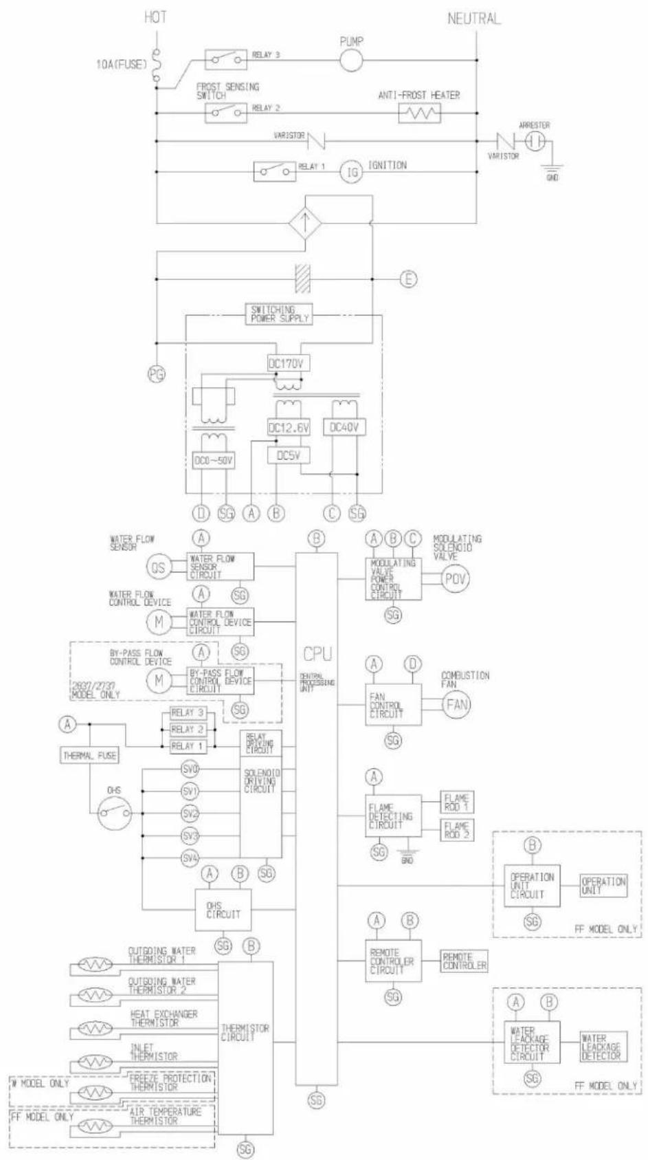
Ladder Diagram
flowchart
Electrical control system diagram showing connections between hot, neutral, and water flow sensors, relays, switches, and temperature monitoring systems.Recirculation Mode
The Rinnai water heater has the ability to control a recirculation pump. Two modes are available, Economy and Comfort, which recirculate the water in the plumbing system to provide hot water more quickly when a tap is opened.
Recirculation mode is for residential installations only. Recirculation mode cannot be used with the Bath Fill controller (BC-100V), an air handler, or with multiple Rinnai water heaters.
The maximum Rinnai temperature setting while in recirculation mode is 140^ F ( 60^ C).
Pump Requirements
Voltage: 120V, 60 Hz
Amperage: less than 2 amps
NOTE: The Rinnai PC board will be damaged if amperage exceeds 2 Amps.
In-rush current: Less than 2.5 Amps.
Check valve: An integral flow check (IFC) valve is required. See plumbing diagram.
Pump Size
The pump should be sized for 2.5 GPM at the pressure loss through the tankless water heater and the supply and return plumbing in the recirculation loop.
For more information on sizing the pump refer to the Rinnai Circ-Logic™ Guide or the section "Pump Sizing for Circulation" in the Rinnai Hot Water System Design Manual.
Installation
- Turn off the electrical power supply by unplugging the power cord or by turning off the electricity at the circuit breaker.
- Install the recirculation pump on the return line according to the pump manufacturer installation instructions. Install a check valve in the return line as shown in the Plumbing Diagram if one is not integrated into the pump.
- The wire harness for the recirculation pump is bundled with the wire harness from the PC board. The connector has a black and white wire with the label "Cut wire to connect to pump". To connect to the pump, cut the connector, splice the wires, and add 4 Amp fuse to the hot wire (black) of the pump. Connect the ground wire from the pump to a screw at the base of the water cabinet. Refer to the Pump Electrical Connection Diagram. Follow Electrical Code and pump manufacturers
recommendations.
- Adjust the dip switch by moving the 4th switch in the whie set of switches (SW2) to ON.
For Economy mode, set the 8th switch in the white set of switches (SW2) to OFF (default). For Comfort mode, set the 8th switch in the white set of switches (SW2) to ON.
| Settings for SW2(bank of white switches) | ||
| Switch 4 Switch 8 | ||
| Economy Mode | ON | OFF |
| Comfort Mode | ON | ON |
- Connect power to the water heater. Press the Power button on the controller. The pump and water heater will turn on to raise the recirculation loop temperature.

flowchart
graph TD
    A["Hot Water Supply Line (minimum 3/4°)"] --> B["Recirculation Loop"]
    B --> C["Electrical Connection (POWER)"]
    C --> D["PUMP"]
    D --> E["RETURN LINE (minimum 3/4°)"]
    E --> F["HOT WATER OUTLETS"]
    E --> G["THERMAL EXPANSION TANK"]
    G --> H["COLD WATER SUPPLY LINE"]
    H --> I["SCALE CONTROL (RECOMMENDED)"]
    I --> J["CHECK VALVE"]
    J --> K["Check Valve"]
    K --> L["DO NOT install the Rinnai Scale Control system within the recirculation loop."]
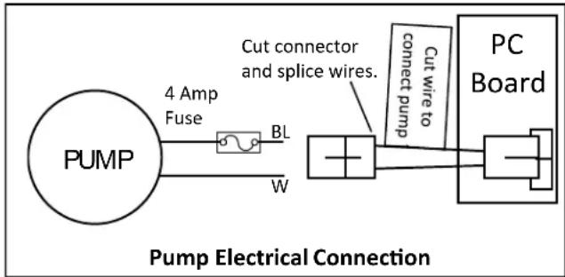
text_image
PUMP 4 Amp Fuse BL W Cut connector and splice wires. Cut wire to connect pump PC Board Pump Electrical ConnectionRecirculation Mode
Sequence of Operation
DIP switches (SW2 - white switches, #4, #8) should be set correctly for recirculation and mode. The Rinnai water heater should be turned on.
Pump recirculation begins when the water heater is turned on. The Rinnai inlet and outlet thermistors measure the water temperature.
The water heater produces hot water at the temperature setting. If the inlet thermistor detects abnormal temperature then diagnostic code 51 is generated and the pump will turn off.
When the return water temperature reaches approximately 15^ F ( 8.3^ C) below the temperature setting, the water heater and pump will turn off.
The cycle will restart at the approximate time interval in the table based on the temperature thermistor readings.
Economy Mode
The Economy mode operates as follows:
• Less energy consumed due to fewer pump cycles
• Assumes plumbing is insulated (minimal pipe heat loss)
- Pump cycles on every 31 to 79 minutes (see table).
Comfort Mode
The Comfort mode operates as follows:
- Higher energy consumption due to more pump cycles
• Assumes plumbing is not insulated resulting in higher pipe heat loss - Pump cycles on every 15 to 39 minutes (see table).
| Rinnai Temperature Setting°F | Typical Pump ON Intervals* | |
| Economy Mode | Comfort Mode | |
| 140 31 15 | ||
| 135 31 15 | ||
| 130 31 15 | ||
| 125 31 15 | ||
| 120 31 15 | ||
| 115 35 18 | ||
| 110 42 21 | ||
| 108 45 22 | ||
| 106 49 24 | ||
| 104 54 27 | ||
| 102 60 30 | ||
| 100 68 34 | ||
| 98 79 39 | ||
* The pump will cycle on at these calculated intervals which are based on the temperature setting, insulation, and estimated heat loss in the system. The values for your installation may vary.
The optional MC195T-US controller provides a timer function to control the on/off periods of the recirculation pump.
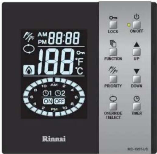
text_image
AM 88:00 PM 188°F ON OFF Rinnai 10 AM 2 6 4 2 PM 10 6 8 10 AM 2 FUNCTION UP PRIORITY DOWN OVERRIDE / SELECT TIMER MC-195T-USRinnai®
Direct Vent Tankless Water Heater Operation Instructions
FOR INDOOR APPLICATIONS ONLY
RL75i...... REU-VC2528FFUD-US
REU-VC2528FFUD-US(A)
RLX94i...... REU-VC2737FFUD-US
RL94i.... REU-VC2837FFUD-US
FOR OUTDOOR APPLICATIONS ONLY
RL75e.... REU-VC2528WD-US
REU-VC2528FFUD-US(A)
RL94e...... REU-VC2837WD-US
natural_image
Line drawing of a rectangular industrial vessel with control panel and mounting feet (no text or symbols)
natural_image
Line drawing of a rectangular electronic device with a central panel and mounting base (no text or symbols)Important Facts about your Water Heater
Thank you for purchasing a Rinnai Tankless Water Heater. For proper operation and safety, it is important to follow the instructions and adhere to the safety precautions.
Read all of the instructions and the warranty thoroughly before operating this water heater. Keep this manual in a safe place.
NOTICE: Rinnai sometimes shares customer contact information with businesses that we believe provide products or services that may be useful to you. By providing this information, you agree that we can share your contact information for this purpose. If you prefer not to have your information shared with these businesses, please contact customer service and ask not to have your information shared. We will however, continue to contact you with information relevant to the product(s) you registered and/or you account with us.

WARNING
If the information in these instructions is not followed exactly, a fire or explosion may result causing property damage, personal injury, or death.
— Do not store or use gasoline or other flammable vapors and liquids in the vicinity of this or any other appliance.
— WHAT TO DO IF YOU SMELL GAS
- Do not try to light any appliance.
- Do not touch any electrical switch; do not use any phone in your building.
- Immediately call your gas supplier from a neighbor's phone. Follow the gas supplier's instructions.
- If you cannot reach your gas supplier, call the fire department.
— Installation and service must be performed by a licensed professional.
Consumer Operation Guidelines for the Safe Operation of your Water Heater
w these instructions exactly, a fire or explosion may result causing property damage, personal injury, or loss of life.
A. This appliance does not have a pilot. It is equipped with an ignition device which automatically lights the burner. Do not try to light the burner by hand.
B. BEFORE OPERATING smell all around the appliance area for gas. Be sure to smell next to the floor because some gas is heavier than air and will settle on the floor.
WHAT TO DO IF YOU SMELL GAS
- Do not try to light any appliance.
- Do not touch any electric switch; do not use any phone in your building.
- Immediately call your gas supplier from a
neighbor's phone. Follow the gas supplier's instructions.
- If you cannot reach your gas supplier, call the fire department.
C. Use only your hand to push in or turn the gas control knob. Never use tools. If the knob will not push in or turn by hand, do not try to repair it, call a qualified licensed professional. Force or attempted repair may result in a fire or explosion.
D. Do not use this appliance if any part has been under water. Immediately call a qualified licensed professional to inspect the appliance and to replace any part of the control system and any gas control which has been under water.
OPERATING INSTRUCTIONS
- STOP! Read the safety information above.
- Set the thermostat to lowest setting.
- Turn off all electric power to the appliance using the ON/OFF button.
- This appliance is equipped with an ignition device which automatically lights the burner. Do not try to light the burner by hand.
- Locate the manual gas valve on the side of the heater. Turn the manual valve clockwise to the full OFF position.

text_image
Manual Valve CLOSE OPEN- Wait five (5) minutes to clear out any gas. Then smell for gas, including near the floor. If you smell gas, STOP! Follow "B" in the safety information above. If you don't smell gas, go to the next step.
- Turn the manual gas valve counterclockwise to the full ON position.
- Turn on all electric power to the appliance using the ON/OFF button.
- Set the thermostat to desired setting.
- Open a hot water tap. If the appliance will not operate, follow the instructions "To Turn Off Gas To Appliance" and call your licensed professional or gas supplier. See manual for additional information.
TO TURN OFF GAS TO APPLIANCE
- Turn off all electric power to the appliance using the ON/OFF button.
-
Set the thermostat to lowest setting.
-
Locate the manual gas valve on the side of the heater. Turn the manual valve clockwise to the full OFF position.
32 VC Series Manual
How to use the Temperature Controller
The MC-91-2 controller is the standard temperature controller that is supplied with the water heater. On indoor models it is integrated into the front panel. The MCC-91-2 controller is for hydronic applications requiring higher temperatures. When the MCC-91-2 controller is connected, these higher temperatures are available on all controller models in the system. Refer to the section on temperature ranges.
DO NOT repeatedly operate the water heater and then use a hot water tap while the controller is turned off. Operating the water heater in this way to alternately produce hot water may cause water to condense on the outside of internal parts and accumulate in the water heater cabinet.
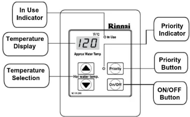
flowchart
graph TD
    A["In Use Indicator"] --> B["Rinnai"]
    C["Temperature Display"] --> B
    D["Temperature Selection"] --> B
    B --> E["120°C"]
    E --> F["Hot water temp."]
    F --> G["Priority Button"]
    F --> H["Priority Indicator"]
    F --> I["On/Off Button"]
Dimensions (inches): 3.5 W x 4.75 H x 0.75 D

WARNING
- Before operating, smell all around the appliance area for gas. Be sure to smell next to the floor because some gas is heavier than air and will settle on the floor.
- Keep the area around the appliance clear and free from combustible materials, gasoline, and other flammable vapors and liquids.
- Always check the water temperature before entering a shower or bath.
- Do not use this appliance if any part has been under water. Immediately call a licensed professional to inspect the appliance and to replace any part of the control system and any gas control which has been under water.
- Should overheating occur or the gas supply fail to shut off, turn off the manual gas control valve to the appliance.
-
Do not adjust the DIP switch unless specifically instructed to do so.
-
Do not use an extension cord or an adapter plug with this appliance.
- Any alteration to the appliance or its controls can be dangerous and will void the warranty.
- If you install this water heater in an area that is known to have hard water or that causes scale build-up the water must be treated and/or the heat exchanger flushed regularly. Rinnai provides a “Scale Control System” that offers superior lime scale prevention and corrosion control by feeding a blend of control compounds into the water supply. Damage and repair due to corrosive compounds in the air is not covered by warranty.
- Keep the air intake location free of chemicals such as chlorine or bleach that produce fumes. These fumes can damage components and reduce the life of your appliance. Damage and repair due to scale in the heat exchanger is not covered by warranty.
How to Set the Temperature
This water heater requires a minimum flow rate to operate. This rate can be found on the specification page in this manual. In some cases when you are not getting hot water or if the water alternates between hot and cold, it is due to the water flow being below or close to the minimum flow rate. Increasing the flow rate should resolve these problems in these cases.
If you are experiencing issues with higher temperature settings, then reduce the temperature setting. Selecting a temperature closer to that which is actually used at the faucet will increase the amount of hot water being delivered to the faucet, due to less cold water mixing at the fixture.

DANGER

text_image
HOT BURNWater temperatures over 125^ F ( 52^ C) can cause severe burns or scalding resulting in death.
Hot water can cause first degree burns with exposure for as little as:
3 seconds at 140^ F ( 60^ C)
20 seconds at 130^ F ( 54^ C)
8 minutes at 120° F (49° C)
Children, disabled, or elderly are at highest risk of being scalded.
Feel water before bathing or showering.
O

- If the water heater is off, press the Power button to turn on.
- If the Priority light is off, then press the "Priority button" on the temperature controller. The green Priority light will glow indicating that this controller is controlling the temperature and that the water heater is ready to supply hot water. (The priority can only be changed while no hot water is running.)
- Press the up or down buttons to obtain the desired temperature setting.
All hot water sources are able to provide water at this temperature setting until it is changed again at this or another temperature controller.
NOTICE
While any hot water is being provided, the temperature setting can only be adjusted between 98^ F and 110^ F.
NOTICE
Check local codes for the maximum water temperature setting allowed when used in nursing homes, schools, day care centers, and all other public applications.
NOTICE
If a newly installed unit with a controller has not been powered for at least 6 hours then the temperature will return to the default setting of 104^ F ( 40^ C) if power is interrupted.
NOTICE
There may be a variation between the temperature displayed on the temperature controller and the temperature at the tap due to weather conditions or the length of pipe to the water heater.
Hot water temp.

Temperatures Available with a Controller
The water heater can deliver water at only one temperature setting at a time. The available temperatures are provided below. A temperature lower than 98^ F ( 37^ C) can be obtained at the tap by mixing with cold water.
To change the temperature scale from Celsius to Fahrenheit or vice versa, press and hold the "On/Off" button for 5 seconds while the water heater is OFF.
| Temperature Settings Available (Fahrenheit °F) | ||||||||||||||||
| RL75i, RL75e | 98 | 100 | 102 | 104 | 106 | 108 | 110 | 115 | 120 | 125* | 130* | 135* | 140* | 150** | 160** | 185** |
| RL94i, RLX94i, RL94e | ||||||||||||||||
| Celsius °C | 37 | 38 | 39 | 40 | 41 | 42 | 43 | 46 | 49 | 52 | 54 | 57 | 60 | 66 | 71 | 85 |
* Temperature settings from 125-140 °F (52-60 °C) are available by setting switch 6 to ON in the SW1 Dip switch (tan switches). These models have a default maximum temperature of 120° F (49° C) and an option (switch 6) to increase the maximum temperature to 140 °F (60 °C).
** These settings require the MCC-91-2 controller. When the MCC-91-2 controller is connected, these higher temperatures are available on all controller models in the system. Use of an MCC-91-2 controller in a residential dwelling will reduce the warranty coverage to that of a commercial warranty application.

WARNING
DO NOT adjust the other switches unless specifically instructed to do so.
These temperatures are suggestions only:
- Kitchen 120 °F (49° C)
• Shower 98 - 110 °F (37 - 43 °C)
• Bath Fill 102 - 110 °F (39 - 43 °C)
Alternate Temperature Settings
A different range of temperature settings is available by setting switches 2 and 3 of the SW2 dip switch (white switches) to ON. The table below shows the settings available with the MC-91-2 and MCC-91-2 controller.

WARNING
MC-91-1, MCC-91-1, MC-100V-1, and BC-100V-1 controllers are not compatible with Alternate Temperature Settings. Alternate Temperature Settings are for commercial applications only.
DO NOT use the MC-91-1, MCC-91-1, MC-100V-1, or BC-100V-1 controllers when dip switches 2 and 3 (white switches) are in the ON position.

other
Alternate Temperature Settings Available (Fahrenheit °F) | Climate | Temperature Setting | Temperature (°C) | Value | |---|---|---|---| | ML-91-2 | RL75i, RL75e | 110 | 110 | | ML-91-2 | RL94i, RLX94i, RL94e | 43 | 43 | | ML-91-2 | RL75i, RL75e | 115 | 115 | | ML-91-2 | RL94i, RLX94i, RL94e | 46 | 46 | | ML-91-2 | RL75i, RL75e | 120 | 120 | | ML-91-2 | RL94i, RLX94i, RL94e | 49 | 49 | | ML-91-2 | RL75i, RL75e | 125 | 125 | | ML-91-2 | RL94i, RLX94i, RL94e | 52 | 52 | | ML-91-2 | RL75i, RL75e | 130 | 130 | | ML-91-2 | RL94i, RLX94i, RL94e | 54 | 54 | | ML-91-2 | RL75i, RL75e | 135 | 135 | | ML-91-2 | RL94i, RLX94i, RL94e | 60 | 60 | | ML-91-2 | RL75i, RL75e | 140 | 140 | | ML-91-2 | RL94i, RLX94i, RL94e | 63 | 63 | | ML-91-2 | RL75i, RL75e | 145 | 145 | | ML-91-2 | RL94i, RLX94i, RL94e | 66 | 66 | | ML-91-2 | RL75i, RL75e | 150 | 150 | | ML-91-2 | RL94i, RLX94i, RL94e | 68 | 68 | | ML-91-2 | RL75i, RL75e | 155 | 155 | | ML-91-2 | RL94i, RLX94i, RL94e | 71 | 71 | | ML-91-2 | RL75i, RL75e | 160 | 160 | | ML-91-2 | RL94i, RLX94i, RL94e | 165 | 165 | | ML-91-2 | RL75i, RL75e | 170 | 170 | | ML-91-2 | RL94i, RLX94i, RL94e | 175 | 175 | | ML-91-2 | RL75i, RL75e | 180 | 180 | | ML-91-2 | RL94i, RLX94i, RL94e | 82 | 82 | | ML-91-2 | RL75i, RL75e | 85 | 85 | ML-91-2: MC-91-2 MCC-91-2Temperature Options Without a Temperature Controller
The default temperature setting for this appliance installed without a temperature controller is 120^ F ( 49^ C). If desired, the temperature setting can be changed to 140^ F ( 60^ C) by adjustment of a switch.
In the SW1 Dip switch (tan switches), set switch 5 to ON to obtain 140^ F water temperature setting. Set switch 5 to OFF (default) to obtain 120^ F water temperature setting. If a temperature controller is installed, then switch 5 has no effect on temperature settings.
Setting Controller to Mute
On the MC-91-2 to eliminate the beeps when keys are pressed or to turn the beeps back on, press and hold both the up and down buttons until a beep is heard (approximately 5 seconds).
Locking the Controller
The MC-91-2 controller can be locked by pressing the Priority button and the up button together for 5 seconds. A beep will sound confirming that the controller is locked. The display will alternately show "LOC", the temperature setting, and a diagnostic code if one has been activated. All of the controllers in the system are also locked.
To unlock the controller press the Priority button and the up button together for 5 seconds.
Diagnostic Codes
This water heater is designed to display diagnostic codes. If there is a potential operation concern refer to the code and remedy on the next page.
To Display Diagnostic Information
To display the most recent diagnostic information codes press and hold the "On/Off" button for 2 seconds on the MC-91-2 controller. While holding the "On/Off" button press the up button. The last 9 diagnostic codes will flash one after the other. To exit this mode press the "On/Off" and up button as before.
To enter or exit the maintenance monitor information mode press and hold the down button for 2 seconds and without releasing it press the ON/OFF button.
To obtain the water flow rate press the up or down buttons until "01" displays. The water flow rate will then appear. For example "58" means 5.8 gal/min.
To obtain the outgoing water temperature press the up or down buttons until "02" displays. The temperature will appear in degrees Fahrenheit.
| Data Unit No. | ||
| 01 | Water flow rate | 0.1 gal/min |
| 02 | Outgoing water temperature | Degrees Fahrenheit |
Diagnostic Codes and Remedies

WARNING
Some of the checks below should be done by a licensed professional. Consumers should never attempt any action that they are not qualified to perform.
| Code Definition Remedy | |||
| 03 | Power interruption during Bath Fill (Water will not flow when power returns). | Turn off | all hot water taps. Press ON/OFF twice. |
| 10 Air Supply or Exhaust Blockage | Check that nothing is blocking the flue inlet or exhaust.Check all vent components for proper connections. | ||
| licensed professional only | Ensure approved venting materials are being used.Ensure vent length is within limits.Verify dip switches are set properly.Check fan for blockage. | ||
| 11 No Ignition(heater not turning on) | Check that the gas is turned on at the water heater, gas meter, or cylinder.If the system is propane, make sure that gas is in the tank.Ensure appliance is properly grounded. | ||
| licensed professional only | Ensure gas type and pressure is correct.Ensure gas line, meter, and/or regulator is sized properly.Bleed all air from gas lines.Verify dip switches are set properly.Ensure igniter is operational.Check igniter wiring harness for damage.Check gas solenoid valves for open or short circuits.Remove burner cover and ensure all burners are properly seated.Remove burner plate and inspect burner surface for condensation or debris.Check the ground wire for the PC board. | ||
| 12 No Flame | Check that the gas is turned on at the water heater, gas meter, or cylinder.Check for obstructions in the flue outlet.If the system is propane, make sure that gas is in the tank. | ||
| licensed professional only | Ensure gas line, meter, and/or regulator is sized properly.Ensure gas type and pressure is correct.Bleed all air from gas lines.Ensure proper venting material was installed.Ensure condensation collar was installed properly.Ensure vent length is within limits.Verify dip switches are set properly.Check power supply for loose connections.Check power supply for proper voltage and voltage drops.Ensure flame rod wire is connected.Check flame rod for carbon build-up.Disconnect and reconnect all wiring harnesses on unit and PC board.Check for DC shorts at components.Check gas solenoid valves for open or short circuits.Remove burner plate and inspect burner surface for condensation or debris. | ||
| 14 | Thermal Fuse has activated | Check for restrictions in air flow around unit and vent terminal. | |
| licensed professional only | Ensure dip switch 5 in the second bank of dip switches (white) is in the off position.Check gas type of unit and ensure it matches gas type being used.Check for low water flow in a circulating system causing short-cycling.Ensure dip switches are set to the proper position.Check for foreign materials in combustion chamber and/or exhaust piping.Check heat exchanger for cracks and/or separations.Check heat exchanger surface for hot spots which indicate blockage due to scale build-up. Refer to instructions in manual for flushing heat exchanger. Hard water must be treated to prevent scale build up or damage to the heat exchanger.Measure resistance of safety circuit.Ensure high fire and low fire manifold pressure is correct.Check for improper conversion of product. | ||
| 16 | Over Temperature Warning (safety shutdown because unit is too hot) | Check for restrictions in air flow around unit and vent terminal. | |
| licensed professional only | Check for low water flow in a circulating system causing short-cycling.Check for foreign materials in combustion chamber and/or exhaust piping.Check for blockage in the heat exchanger. | ||
| Code | Definition Remedy | ||
| 19 Electrical Grounding | licensed professional only | Check all components for electrical short. | |
| 32 | Outgoing Water Temperature Sensor | Check sensor wiring for damage.Measure resistance of sensor.Clean sensor of scale build-up.Replace sensor. | |
| 33 | Heat Exchanger Outgoing Temperature Sensor | ||
| 34 | Combustion Air Temperature Sensor | Check for restrictions in air flow around unit and vent terminal.Check sensor wiring for damage.Measure resistance of sensor.Clean sensor of scale build-up.Ensure fan blade is tight on motor shaft and is in good condition.Replace sensor. | |
| 41 | Outside temperature thermistor (outdoor models only) | Check sensor wiring for damage.Measure resistance of sensor.Clean sensor of scale build-up.Replace sensor. | |
| 51 | Inlet water temperature thermistor | ||
| 52 | Modulating Solenoid Valve Signal | Check modulating gas solenoid valve wiring harness for loose or damaged terminals.Measure resistance of valve coil. | |
| 61 Combustion Fan | Ensure fan will turn freely.Check wiring harness to motor for damaged and/or loose connections.Measure resistance of motor winding. | ||
| 65 Water Flow Control | The water flow control valve has failed to close during the bath fill function. Immediately turn off the water and discontinue the bath fill function. Contact a licensed professional to service the appliance. | ||
| 70 PC Board | Check PC board DIP switches for correct position.Check the connection harness at the connection on the PC board.Replace PC board. | ||
| 71 | Solenoid Valve Circuit | Replace the PC Board. | |
| 72 | Flame Sensing Device | Replace PC Board | |
| 79 Water Leak Detected | Water has been detected at the bottom of the unit. Turn off water supply. Check all plumbing internally for leakage. | ||
| LC# (LC0, LC1, LC2,...) | Scale Build-up in Heat Exchanger (when checking maintenance code history, "00" is substituted for "LC") | LC0~LC9 indicates that there is scale build up in the heat exchanger and that the heat exchanger needs to be flushed to prevent damage. Refer to the flushing instructions in the manual. Hard water must be treated to prevent scale build up or damage to the heat exchanger.To operate the water heater temporarily until the heat exchanger can be flushed, push the On/Off button on the temperature controller 5 times. Repeated LC codes will eventually lockout the water heater.Please call Rinnai technical department. | |
| FF | Maintenance has been performed | Indicates a licensed professional performed maintenance or corrected an issue. | |
| No code | Nothing happens when water flow is activated. | Clean inlet water supply filter.On new installations ensure hot and cold water lines are not reversed.Verify you have at least the minimum flow rate required to fire unit. | |
| licensed professional only | Check for cold to hot cross over. Isolate circulating system if present. Turn off cold water to the unit, open pressure relief valve; if water continues to flow, there is bleed over in your plumbing.Verify turbine spins freely.Measure the resistance of the water flow control sensor.If the display is blank and clicking is coming from the unit, disconnect the water flow servo motor (GY, BR, O, W, P, BL, R). If the display comes on then replace the water flow servo motor. | ||
Required Maintenance
The appliance and vent system must be inspected annually by a licensed professional. Repairs and maintenance should be performed by a licensed professional. The licensed professional must verify proper operation after servicing.

WARNING
To protect yourself from harm, before performing maintenance:
- Turn off the electrical power supply by unplugging the power cord or by turning off the electricity at the circuit breaker. (The temperature controller does not control the electrical power.)
- Turn off the gas at the manual gas valve, usually located immediately below the water heater.
- Turn off the incoming water supply. This can be done at the isolation valve immediately below the water heater or by turning off the water supply to the building.

WARNING
Keep the appliance area clear and free from combustible materials, gasoline, and other flammable vapors and liquids.
The following maintenance items are required for the proper operation of your water heater.
The appliance must be inspected annually by a licensed professional. Repairs and maintenance should be performed by a licensed professional. The licensed professional must verify proper operation after servicing.
Cleaning
It is imperative that control compartments, burners, and circulating air passageways of the appliance be kept clean.
Clean as follows:
- Turn off and disconnect electrical power. Allow to cool.
- Close the water shut off valves. Remove and clean the water inlet filter.
- Remove the front panel by removing 4 screws.
- Use pressurized air to remove dust from the main burner, heat exchanger, and fan blades. Do not use a wet cloth or spray cleaners on the burner. Do not use volatile substances such as benzene and thinners. They may ignite or fade the paint.
- Use soft dry cloth to wipe cabinet.
Vent System
The vent system and condensate collector (located at top of unit) should be inspected at least annually for blockages or damage. If the vent and/or condensate collector is blocked contact a licensed professional.
Motors
Motors are permanently lubricated and do not need periodic lubrication. However you must keep fan and motor free of dust and dirt by cleaning annually.
Temperature Controller
Use a soft damp cloth to clean the temperature controller. Do not use solvents.
Lime / Scale Build-up
If you receive diagnostic code "LC#" (LC1, LC2,...), refer to the procedure, Flushing the Heat Exchanger. Refer to the section on Water Quality to see if your water needs to be treated or conditioned. (When checking maintenance code history, "00" is substituted for "LC#".)
The water must be potable, free of corrosive chemicals, sand, dirt, or other contaminates. It is up to the installer to ensure the water does not contain corrosive chemicals, or elements that can affect or damage the heat exchanger. Water that contains chemicals exceeding the levels below affect and damage the heat exchanger. Replacement of the heat exchanger due to water quality damage is not covered by the warranty.
Snow Accumulation
Keep the area around flue terminal free of snow and ice. The appliance will not function properly if the intake air or exhaust is impeded (blocked or partially blocked) by obstructions.
Coastal Installations
Installations located in or near coastal areas may require additional maintenance due to corrosive airborne ocean salt.
Clean the water filter
Clean the inlet water filter by closing the cold and hot water inlet isolation (shut-off) valves. Put a bucket under the filter at the bottom of the water heater to
catch any water that is contained inside the unit. Unscrew the water filter. Rinse the filter to remove any debris. Install the filter and open the isolation valves.

WARNING
Testing the pressure relief valve should only be performed by a licensed professional. Water discharged from the pressure relief valve could cause severe burns instantly or death from scalds.
Pressure Relief Valve:
Operate the valve manually once a year. In doing so, it will be necessary to take precautions with regard to the discharge of potentially scalding hot water under pressure. Ensure discharge water has a safe place to flow. Contact with your body or other property may cause damage or harm.
Visual Inspection of Flame
Verify proper operation after servicing. The burner must flame evenly over the entire surface when operating correctly. The flame must burn with a clear, blue, stable flame. See the parts breakdown of the burner for the location of the view ports. The flame pattern should be as shown in the figures below.
SATISFACTORY

text_image
FRONT VIEW BLUE FLAME FLAME RODUNSATISFACTORY
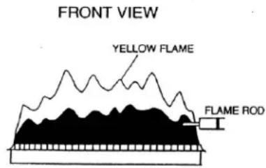
text_image
FRONT VIEW YELLOW FLAME FLAME RODFreeze Protection
Make sure in case of freezing weather that the water heater and its water lines are adequately protected to prevent freezing. Damage due to freezing is not covered by the warranty. Refer to the section on Freeze Protection. The unit may be drained manually. However, it is highly recommended that:
- drain down solenoid valves be purchased and installed that will automatically drain the unit if power is lost. These are available in a kit, 104000059. (The condensate trap is not affected by the auto drain down solenoid valves and will have to be manually drained.)
- a surge protector with terminals be purchased and installed which allows the solenoid valves to operate if the unit is disabled due to a diagnostic code. This is available as 104000057.
Winterizing
These recommendations are intended to suggest practices that are effective for winterizing the water heater. They should be used as a guide only. No liability is assumed for any issues resulting from the use of this information.
GAS
Shut off the gas to the water heater. It is generally preferable to shut off the gas service to the entire location if gas is not going to be used.
WATER
Shut off the cold water supply to the water heater. It is generally preferable to shut off the water to the entire location if water is not going to be used.
Drain the water heater by opening the drain valves on the cold water line and hot water line.
Open several hot water taps and remove the filter assembly at the water inlet in order to allow room for expansion in case there is water in the lines that freeze. Compressed air may be used to purge any water left in the system.
ELECTRIC
Disconnect the power supply by either unplugging the electrical cord or by turning off the circuit breaker to the water heater to prevent potential damage from irregular power surges or interruptions.
VENT TERMINATION
Place a cover over the vent termination (intake and exhaust) if it can be safely accessed. The cover should be easy to apply and remove. This will prevent debris, leaves, and small animals from entering the venting and water heater which could cause air flow issues upon return to service.
Flushing the heat exchanger
An LC0\~LC9 or "00" diagnostic code indicates the unit is beginning to lime up and must be flushed. Failure to flush the appliance will cause damage to the heat exchanger. Damage caused by lime build-up is not covered by the unit's warranty. Rinnai strongly recommends installation of isolation valves to allow for flushing of the heat exchanger.
- Disconnect electrical power to the water heater.
- Close the shutoff valves on both the hot water and cold water lines (V3 and V4).
- Connect pump outlet hose (H1) to the cold water line at service valve (V2).
- Connect drain hose (H3) to service valve (V1).
- Pour 4 gallons of undiluted virgin, food grade, white vinegar into pail.
- Place the drain hose (H3) and the hose (H2) to the pump inlet into the cleaning solution.
- Open both service valves (V1 and V2) on the hot water and cold water lines.
- Operate the pump and allow the vinegar to circulate through the water heater for at least 1 hour at a rate of 4 gallons per minute (15.1 liters per minute).
- Turn off the pump.
- Rinse the vinegar from the water heater as follows:
a. Remove the free end of the drain hose (H3) from the pail. Place in sink or outside to drain.
b. Close service valve, (V2), and open shutoff valve, (V4). Do not open shutoff valve, (V3).
c. Allow water to flow through the water heater for 5 minutes.
d. Close shutoff valve (V4). When unit has finished draining remove the in-line filter at the cold water inlet and clean out any residue. Place filter back into unit and open valve (V4).
e. Close service valve, (V1), and open shutoff valve, (V3).
-
Disconnect all hoses.
-
Restore electrical power to the water heater.
Following flush procedure call technical assistance (1-800-621-9419) for PCB reset information.
KEY
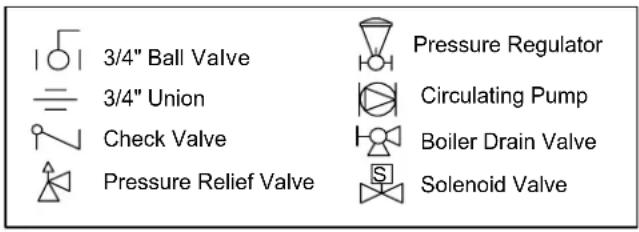
text_image
3/4" Ball Valve 3/4" Union Check Valve Pressure Relief Valve Pressure Regulator Circulating Pump Boiler Drain Valve Solenoid Valve
text_image
In-line Filter V1 V2 V3 Hot Water Line H1 COLD WATER LINE V4 Gas Supply umpManual Draining of the Water Heater

WARNING
To avoid burns, wait until the equipment cools down before draining the water. The water in the appliance will remain hot after it is turned off.
If the water heater is not going to be used during a period of possible freezing weather, it is recommended that the water inside the water heater be drained.
To manually drain the water:
- Shut off cold water supply and gas supply.
- Turn off the temperature controller.
- Disconnect the power to the water heater.
- Place a container to catch the water. Remove the drain caps on both isolation valves and open both valves above the caps (blue and red valve handles). -OR- Open hot water drain plug at the hot water outlet.
- Remove water filter to drain the cold water. Compressed air may be used to purge any water left in the system.
To resume normal operation:
- Confirm that all water drain plugs are removed, that the gas supply is turned off, and that all taps are closed.
- Screw in the water filter in the cold water inlet.
- Replace the drain caps and close both isolation valves. -OR- Screw in the hot water drain plug.
- Open the cold water supply.
- Open a tap and confirm that water flows, and then close.
- Turn on the power.
- After confirming that the temperature controller is off, turn on the gas supply.
- Turn on the temperature controller.
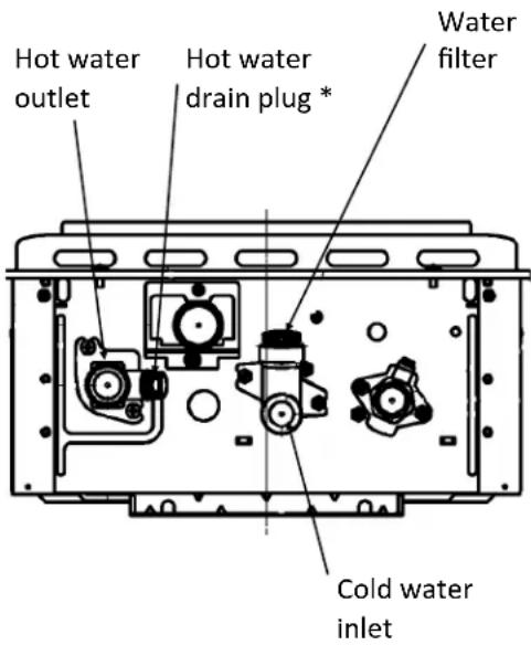
text_image
Hot water outlet Hot water drain plug * Water filter Cold water inlet* Use a wrench or other tool to unscrew the hot water drain plug.
Running a low volume of water through the water heater to prevent freezing
If the temperature exceeds the ability of the water heater to freeze protect itself, or if power is lost, the following steps may prevent the water heater and external piping from freezing. (Units connected with EZ Connect (2 unit link) should be drained to prevent freezing if not in use.)
- Turn the water heater off.
- Close the gas supply valve.
- Turn on a hot water tap to flow water about 0.1 gal/min or where the stream is about 0.2 inches thick.
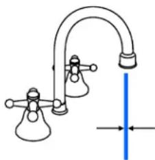
natural_image
Simple line drawing of a laboratory apparatus with a vertical blue line and two flasks (no text or symbols)0.1 gal/min or about 0.2 inch thick
When the water heater or external piping has frozen
- Do not operate the water heater if it or the external piping is frozen.
- Close the gas and water valves and turn off the power.
- Wait until the water thaws. Check by opening the water supply valve.
- Check the water heater and the piping for leaks.
42 VC Series Manual
State Regulations
NOTICE BEFORE INSTALLATION
This direct-vent appliance must be installed by a licensed professional. If you are not properly trained, you must not install this unit.
IMPORTANT: In the State of Massachusetts (248 CMR 4.00 & 5.00)
For all side wall horizontally vented gas fueled equipment installed in every dwelling, building or structure used in whole or in part for residential purposes, including those owned or operated by the Commonwealth and where the side wall exhaust vent termination is less than seven (7) feet above finished grade in the area of the venting, including but not limited to decks and porches, the following requirements shall be satisfied:
- INSTALLATION OF CARBON MONOXIDE DETECTORS. At the time of installation of the side wall horizontal vented gas fueled equipment, the installing plumber or gasfitter shall observe that a hard wired carbon monoxide detector with an alarm and battery back-up is installed on the floor level where the gas equipment is to be installed. In addition, the installing plumber or gasfitter shall observe that a battery operated or hard wired carbon monoxide detector with an alarm is installed on each additional level of the dwelling, building or structure served by the side wall horizontal vented gas fueled equipment. It shall be the responsibility of the property owner to secure the services of qualified licensed professionals for the installation of hard wired carbon monoxide detectors
a. In the event that the side wall horizontally vented gas fueled equipment is installed in a crawl space or an attic, the hard wired carbon monoxide detector with alarm and battery back-up may be installed on the next adjacent floor level. b. In the event that the requirements of this subdivision can not be met at the time of completion of installation, the owner shall have a period of thirty (30) days to comply with the above requirements; provided, however, that during said thirty (30) day period, a battery operated carbon monoxide detector with an alarm shall be installed. - APPROVED CARBON MONOXIDE DETECTORS. Each carbon monoxide detector as required in accordance with the above provisions shall comply with NFPA 720 and be ANSI/UL 2034 listed and IAS certified.
- SIGNAGE. A metal or plastic identification plate shall be permanently mounted to the exterior of the building at a minimum height of eight (8) feet above grade directly in line with the exhaust vent terminal for the horizontally vented gas fueled heating appliance or equipment. The sign shall read, in print size no less than one-half (1/2) inch in size, "GAS VENT DIRECTLY BELOW. KEEP CLEAR OF ALL OBSTRUCTIONS".
- INSPECTION. The state or local gas inspector of the side wall horizontally vented gas fueled equipment shall not approve the installation unless, upon inspection, the inspector observes carbon monoxide detectors and signage installed in accordance with the provisions of 248 CMR 5.08(2)(a)1 through 4.
Combination Space Heating/Potable Water System
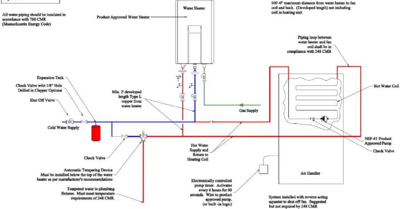
flowchart
graph TD
    A["Product Approved Water Heater"] --> B["Water Heater"]
    B --> C["Expansion Tank"]
    C --> D["Check Valve with 1/8" Hole Drilled in Clapper Optional"]
    D --> E["Shut Off Valve"]
    E --> F["Cold Water Supply"]
    F --> G["Check Valve"]
    G --> H["Automatic Tempering Device Must be installed below the top of the water heater as per manufacturer's recommendations"]
    H --> I["Tempered water to plumbing fixtures. Must meet temperature requirements of 248 CMR."]
    I --> J["Gas Supply"]
    J --> K["Min. 2" developed length Type L copper from water heater"]
    K --> L["Hot Water Supply and Return to Heating Coil"]
    L --> M["Electronically controlled pump timer. Activates every 6 hours for 60 seconds. Wire to product approved pump. (or built-in logic)"]
    M --> N["Air Handler"]
    N --> O["System installed with reverse acting aquastat to shut off fan. Suggested but not required by 248 CMR"]
    P["Piping loop between water heater and fan coil shall be in compliance with 248 CMR"] --> Q["Hot Water Coil"]
    Q --> R["NSF-61 Product Approved Pump Check Valve"]
    R --> S["Air Handler"]
VC Series Manual 43
Replacement Parts
The Technical Sheet that is located inside the front cover of the water heater contains a complete illustrated parts list.
| Tech Sheet | Item No. |
| Gas Control Assembly 100 | |
| Electrode / Flame Rod Kit 116, 117 | |
| Fan Assembly / Motor 125 | |
| Heat Exchanger 143 | |
| Water Flow Servo & Sensor 401 | |
| Bypass-Servo Assembly 403 | |
| Water Filter Assy 412 | |
| PC Board 700 | |
| Ignitor 706 | |
| Thermal Fuse Harness 725 |
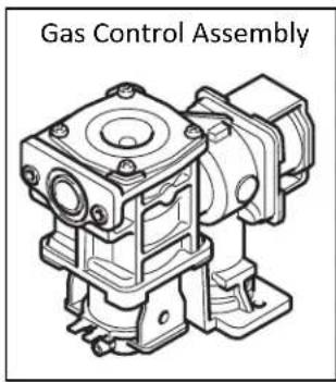
text_image
Gas Control Assembly
text_image
Electrode / Flame Rod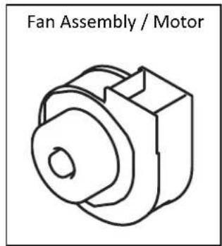
text_image
Fan Assembly / Motor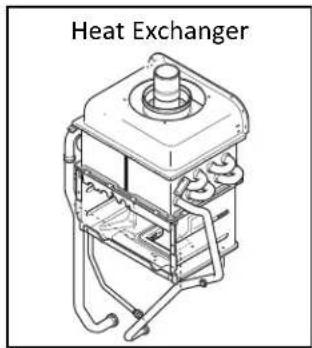
text_image
Heat Exchanger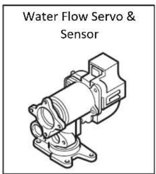
text_image
Water Flow Servo & Sensor
text_image
Bypass-Servo Assembly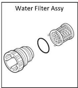
text_image
Water Filter Assy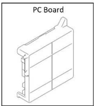
natural_image
Isometric line drawing of a PC Board component (no text or symbols on the diagram itself)
natural_image
Line drawing of an ignition component (no text or symbols on the diagram itself)
text_image
Thermal Fuse HarnessLimited Warranty for Luxury Series RL75, RL94, RLX94i
What is covered?
The Rinnai Standard Limited Warranty covers any defects in materials or workmanship when the product is installed and operated according to Rinnai written installation instructions, subject to the terms within this Limited Warranty document. This Limited Warranty applies only to products that are installed correctly in the United States and Canada. Improper installation may void this Limited Warranty. It is recommended that a trained and qualified professional who has attended a Rinnai installation training class complete your installation. This Limited Warranty coverage, as set out in the table below, extends to the original purchaser and subsequent owners, but only while the product remains at the site of the original installation, and terminates if the product is moved or reinstalled at a new location.
| Item | Period of Coverage (from date of purchase) | ||
| Residential Applications | If used for both residential water heating and space heating purposes | Commercial Applications | |
| Heat Exchanger 12 years | [1] [2] 10 years | [1] [2] 5 years | [1] |
| All Other Parts and Components | 5 years [1] 5 years | [1] 5 years | [1] |
| Reasonable Labor 1 year | [3] 1 year | [3] 1 year | [3] |
[1] Period of coverage is reduced to 3 years from date of purchase when used as a circulating water heater within a hot water circulation loop, where the water heater is in series with a circulation system and all circulating water flows through the water heater, and where an on-demand recirculation system is not incorporated.
On-demand recirculation is defined as a hot water recirculating loop or system that utilizes existing hot and cold lines or a dedicated return line, and only activates when hot water is used. It can be activated by a push button, motion sensor, or voice activation but not by a temperature sensor. A timer added to a standard recirculating pump is not considered as on-demand.
[2] Period of coverage is reduced to 5 years from date of purchase if the Rinnai Tankless Water Heater temperature setting exceeds 160^ F ( 71^ C).
[3] Labor coverage is extended to 5 years in residential applications and 2 years in commercial applications if the product is registered within 30 days (except registration is not required in California and Quebec) and/or if the other conditions above in the Residential Applications and Commercial Applications sections are satisfied.
Note: The integrated controller on indoor models has a 1 year warranty on parts.
What Will Rinnai Do?
Rinnai will repair or replace the covered product or any part or component that is defective in materials or workmanship as set forth in the above table. Rinnai will pay reasonable labor charges associated with the repair or replacement of any such part or component during the term of the labor warranty period. All repair parts must be genuine Rinnai parts. All repairs or replacements must be performed by a qualified professional who is properly trained to do the type of repair.
Replacement of the product may only be authorized by Rinnai at its sole discretion. Rinnai does not authorize any person or company to assume for it any obligation or liability in connection with the replacement of the product. If Rinnai determines that repair of a product is not possible, Rinnai may replace the product with a comparable product at Rinnai's sole discretion. The warranty claim for product parts and labor may be denied if a component or product returned to Rinnai is found to be free of defects in material or workmanship; damaged by improper installation, use or operation; or damaged during return shipping.
How to Obtain Service
For the name of a trained and qualified professional please contact your place of purchase, visit the Rinnai website (www.rinnai.us), call Rinnai at 1-800-621-9419 or write to Rinnai at 103 International Drive, Peachtree City, Georgia 30269.
Proof of purchase is required to obtain warranty service. You may show proof of purchase with a dated sales receipt, or by registering within 30 days of purchasing the product. To register your Rinnai Tankless Water Heater, please visit www.rinnai.us. For those without internet access, please call 1-800-621-9419. Receipt of registration by Rinnai will constitute proof-of-purchase for this product. Registration of product installed in new home construction may be verified with a copy of the closing papers provided by the initial home buyer. However, registration is not necessary in order to validate this Limited Warranty.
What is Not Covered?
This Limited Warranty does not cover any failures or operating difficulties due to the following:
- Accident, abuse, or misuse
- Alteration of the product or any component part
• Misapplication of this product - Improper installation (such as but not limited to)
– Product being installed in a corrosive environment - Condensate damage
- Improper venting
- Incorrect gas type
- Incorrect gas or water pressure
– Absence of a drain pan under the appliance
- Water quality
- Improper maintenance (such as but not limited to scale build-up, freeze damage, or vent blockage)
- Incorrect sizing
- Any other cause not due to defects in materials or workmanship
- Problems or damage due to fires, flooding, electrical surges, freezing or any acts of God.
- Force majeure
There is no warranty coverage on product installed in a closed loop application, commonly associated with space heating only applications.
Use of an MCC-91-2 controller in a residential dwelling will reduce the warranty coverage to that of a commercial warranty application except when an MCC-91-2 is used with a hydronic air handler for temperatures no higher than 160^ F ( 71^ C).
This Limited Warranty does not apply to any product whose serial number or manufacture date has been defaced.
This Limited Warranty does not cover any product used in an application that uses chemically treated water such as a pool or spa heater.
Limitation on Warranties
No one is authorized to make any other warranties on behalf of Rinnai America Corporation. Except as expressly provided herein, there are no other warranties, expressed or implied, including, but not limited to warranties of merchantability or fitness for a particular purpose, which extend beyond the description of the warranty herein.
Any implied warranties of merchantability and fitness arising under state law are limited in duration to the period of coverage provided by this Limited Warranty, unless the period provided by state law is less. Some states do not allow limitations on how long an implied Limited Warranty lasts, so the above limitation may not apply to you.
Rinnai shall not be liable for indirect, incidental, special, consequential or other similar damages that may arise, including lost profits, damage to person or property, loss of use, inconvenience, or liability arising from improper installation, service or use. Some states do not allow the exclusion or limitation of incidental or consequential damages, so the above limitation may not apply to you.
This Limited Warranty gives you specific legal rights, and you may also have other rights which vary from state to state.
www.rinnai.us/warranty
EXTEND THE LABOR COVERAGE UNDER YOUR LIMITED WARRANTY\*
Luxury Series RL75, RL94, RLX94i
REGISTRATION REQUIRED\*
Rinnai is providing the opportunity to extend your Rinnai Standard Limited Warranty on labor only on Luxury Series models RL75, RL94, and RLX94i if you register within 30 days of purchase of your unit. Products not registered will still be covered under the Rinnai standard product limited warranty as provided in the Installation and Operation manual which comes with this product. Warranty information is also available on Rinnai's web site at www.rinnai.us.
RESIDENTIAL APPLICATIONS:
The limited warranty period on the labor coverage for models RL75, RL94, and RLX94i Tankless Water Heaters installed in a residential application is extended for an additional 48 months (a total of 60 months labor coverage from date of purchase), when used in a residential hot water application, if the product is registered within 30 days of purchase at www.rinnai.us/product-registration or by calling 1-866-RINNAI-1 (746-6241), except registration is not required in California and Quebec.
ADDITIONAL CONDITIONS OF EXTENDING THE LABOR COVERAGE UNDER THE LIMITED WARRANTY:
- The labor coverage does NOT extend if the RL75, RL94, and RLX94i Tankless Water Heater is used for structure heating or in a closed loop application.
- If the product is installed on a circulation system, the circulation system must be controlled by an on-demand system, or the limited warranty will not be extended.
COMMERCIAL APPLICATIONS:
The limited warranty period on the labor coverage for models RL75, RL94, and RLX94i Tankless Water Heaters installed in a commercial application is extended for an additional 12 months (a total of 24 months labor coverage from date of purchase), when used in a commercial hot water application, if the product is registered within 30 days of purchase at www.rinnai.us/product-registration or by calling 1-866-RINNAI-1 (746-6241), except registration is not required in California and Quebec.
ADDITIONAL CONDITIONS OF EXTENDING THE LABOR COVERAGE UNDER THE LIMITED WARRANTY:
- The labor coverage does NOT extend if the RL75, RL94, and RLX94i Tankless Water Heater is used for structure heating or in a closed loop application.
- If the product is installed on a circulation system, the circulation system must be controlled by an on-demand system, or the limited warranty will not be extended.
* Only applicable if product is registered within 30 days of purchase and the other conditions are met. Note to California and Quebec Residents, and residents of other jurisdictions that prohibit warranty benefits conditioned on registration, registration is not required to obtain longer warranty periods and failure to register does not diminish your warranty rights. www.rinnai.us/warranty
Rinnai®
POUR DES APPLICATIONS EN INTÉRIEUR UNIQUEMENT
RL75i...... REU-VC2528FFUD-US
REU-VC2528FFUD-US(A)
RLX94i...... REU-VC2737FFUD-US
RL94i...... REU-VC2837FFUD-US
POUR DES APPLICATIONS EN EXTÉRIEUR UNIQUEMENT
RL75e...... REU-VC2528WD-US
REU-VC2528FFUD-US(A)
RL94e...... REU-VC2837WD-US
natural_image
Line drawing of a rectangular industrial or gas storage unit with control panel and mounting base (no text or symbols)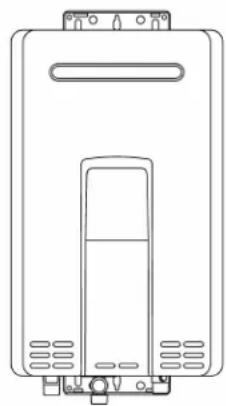
natural_image
Line drawing of a rectangular electronic device with ventilation slots and a central panel (no text or symbols)
Low Lead Content
NSF/ANSI 372

SANITATION

ANS Z21.10.3 • CSA 4.3
LISEZ SOIGNEUSEMENT TOUTES CES INSTRUCTIONS AVANT D'INSTALLER OU D'UTILISER CE CHAUFFE-EAU.
natural_image
Technical line drawing of a pipe fitting with a valve and housing (no text or symbols)RL75i, RL94i, RLX94i

text_image
14,04 (356,6) 22,95 (583)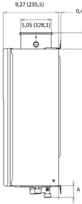
text_image
9,27 (235,5) 5,05 (128,1) 0,4 A
text_image
~1,8 (10~45) Variable 2.67 (67.8) ENTRÉE D'EAU FROIDE CONNEXION DE GAZ SORTIE D'EAU CHAUBE C E D F G| DIMENSION | Pouces (mm) | DIMENSION | Pouces (mm) |
| A (GAZ) | 1,31 (33,2) | D | 4,33 (110) |
| A (FROID) | 1,93 (49) | E | 2,89 (73.3) |
| A (CHAUD) | 1,35 (34,4) | F | 1,85 (47) |
| B | 4,21 (106,9) | G | 3,44 (87,3) |
| C | 1,17 (29,8) |
RL75e, RL94e
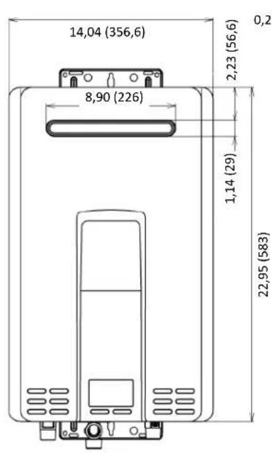
text_image
14,04 (356,6) 8,90 (226) 2,23 (56,6) 1,14 (29) 22,95 (583) 0,2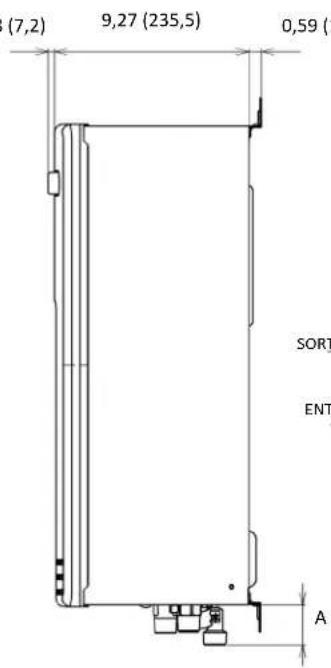
text_image
(7,2) 9,27 (235,5) 0,59 SORT ENT A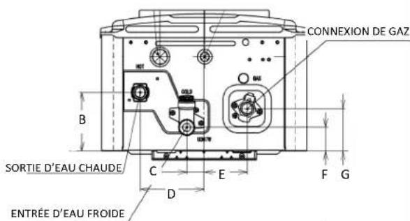
text_image
CONNEXION DE GAZ SORTIE D'EAU CHAUDE ENTRÉE D'EAU FROIDE| DIMENSION | Pouces (mm) | DIMENSION | Pouces (mm) |
| A (GAZ) | 1,31 (33,2) | D | 4,33 (110) |
| A (FROID) | 1,93 (49) | E | 2,91 (73,8) |
| A (CHAUD) | 1,35 (34,4) | F | 1,61 (40,8) |
| B | 3,96 (100,7) | G | 2,87 (73) |
| C | 1,17 (29,8) |
line
| Delta T – Montée en température (°F) | DLX94i | RL94 | RL75 | | ------------------------------------ | ------ | ---- | ---- | | 0 | 10.0 | 10.0 | 7.5 | | 25 | 10.0 | 10.0 | 7.5 | | 50 | 10.0 | 10.0 | 7.5 | | 75 | 10.0 | 10.0 | 7.5 | | 100 | 10.0 | 10.0 | 7.5 | | 125 | 10.0 | 10.0 | 7.5 | | 150 | 8.0 | 8.5 | 7.5 | | 175 | 6.0 | 7.0 | 6.5 | | 200 | 4.5 | 5.5 | 5.0 | | 225 | 3.5 | 4.5 | 4.0 | | 250 | 3.0 | 3.5 | 3.0 | | 275 | 2.5 | 3.0 | 2.5 | | 300 | 2.2 | 2.5 | 2.2 | | 325 | 2.0 | 2.2 | 2.0 | | 350 | 1.8 | 2.0 | 1.8 | | 375 | 1.6 | 1.8 | 1.6 | | 400 | 1.4 | 1.6 | 1.4 | | 425 | 1.2 | 1.4 | 1.2 | | 450 | 1.0 | 1.2 | 1.0 | | 475 | 0.8 | 1.0 | 0.8 | | 500 | 0.6 | 0.8 | 0.6 | | 525 | 0.4 | 0.6 | 0.4 | | 550 | 0.2 | 0.4 | 0.2 | | 575 | 0.1 | 0.2 | 0.1 | | 600 | - | - | - | | 625 | - | - | - | | 650 | - | - | - | | 675 | - | - | - | | 700 | - | - | - | | 725 | - | - | - | | 750 | - | - | - | | 775 | - | - | - | | 800 | - | - | - | | 825 | - | - | - | | 850 | - | - | - | | 875 | - | - | - | | 900 | - | - | - | | 925 | - | - | - | | 950 | - | - | - | | 975 | - | - | - | | 1000 | - | - | - | | The data is already in CSV format with NaN values for all three series: DLX94i, RL94, and RL75. The values are estimated based on the formula G = (G / (T)). The data is presented in a table format with columns for each series and the corresponding values at the end of the table.natural_image
Line drawing of a rectangular industrial vessel with control panel and mounting feet (no text or symbols)
natural_image
Line drawing of a rectangular electronic device with ventilation slots and a central control panel (no text or symbols)Dimensions (pouces): 3.5 W x 4.75 H x 0.75 D

AVERTISSEMENT
text_image
HOT BRÛLUREnatural_image
Simple line drawing of a laboratory apparatus with two funnels and a curved tube, no text or symbols present.natural_image
Line drawing of an Allumeur electrical component (no text or symbols on the diagram itself)
text_image
Faisceau de fusible thermiquewww.rinnai.us/warranty
EXTENSION DE LA COUVERTURE EN MAIN-D'ŒUVRE AVEC VOTRE GARANTIE LIMITÉE\*
RL75, RL94, RLX94i de Série Luxury
ENREGISTREMENT NÉCESSAIRE\*
natural_image
Product lineup of industrial air conditioning units including Rinnai and various pressure regulators (no visible text or labels)Learn more about Rinnai high-performance Tankless Water Heaters, Hybrid Water Heating Systems, Boilers, Vent-Free Fan Convectors and EnergySaver® Direct Vent Wall Furnaces at:
rinnai.us | rinnai.ca
Rinnai®
Rinnai America Corporation • 103 International Drive, Peachtree City, GA 30269 1-800-621-9419 • rinnai.us
©2019 Rinnai America Corporation. Rinnai America Corporation continually updates materials, and as such, content is subject to change without notice. Local, state, provincial, federal and national fuel gas codes must be adhered to prior to and upon installation.
U307-0710X04(02)
100000244(12)
8/2019