
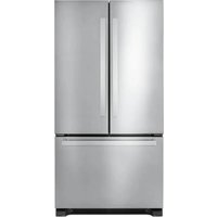
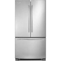
W10663564 - Refrigerator JENN-AIR - Free user manual and instructions
Find the device manual for free W10663564 JENN-AIR in PDF.
| Product Type | Built-in Refrigerator |
| Brand | JENN-AIR |
| Model | W10663564 (Refer to panel installation manual) |
| Dimensions (H x W x D) | Approximately 213 cm x 91 cm x 61 cm (depending on configuration) |
| Weight | Approximately 160 kg (depending on model) |
| Power Supply | 115 V, 60 Hz, 15 A |
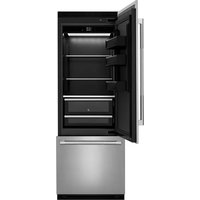
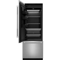
| Freezer Type | Bottom Freezer (depending on model) or Side-by-Side |
| Main Functions | Refrigeration and freezing, cold air distribution, LED lighting |
| Control | Electronic, integrated control panel |
| Lighting | LED inside refrigerator and freezer |
| Safety | Secondary anti-tip panel included, door locks |
| Installation | Built-in, requires custom panels (not included) |
| Maintenance and Cleaning | Clean with a soft cloth and mild detergent; automatic defrost |
| Spare Parts and Repairability | Parts available from Jenn-Air; repair by authorized technician |
| Product Registration | Online registration recommended (jennair.com/customer-care) |
Frequently Asked Questions - W10663564 JENN-AIR
User questions about W10663564 JENN-AIR
0 question about this device. Answer the ones you know or ask your own.
Ask a new question about this device
Download the instructions for your Refrigerator in PDF format for free! Find your manual W10663564 - JENN-AIR and take your electronic device back in hand. On this page are published all the documents necessary for the use of your device. W10663564 by JENN-AIR.
USER MANUAL W10663564 JENN-AIR
natural_image
Architectural line drawing of a room layout with furniture and fixtures (no text or symbols)INTRODUCTION
SAFETY
Your safety and the safety of others are very important.
We have provided many important safety messages in this manual and on your appliance. Always read and obey all safety messages.

This is the safety alert symbol.
This symbol alerts you to potential hazards that can kill or hurt you and others.
All safety messages will follow the safety alert symbol and either the word "DANGER" or WARNING." These words mean:
DANGER
WARNING
All safety messages will tell you what the potential hazard is, tell you how to reduce the chance of injury, and tell you what can happen if the instructions are not followed.
You can be killed or seriously injured if you don't immediately follow instructions.
You can be killed or seriously injured if you don't immediately follow instructions.
INTRODUCTION
TABLE OF CONTENTS
INTRODUCTION
Safety 3
Registration 4
Registering Your Product 4
Product Identification 4
SITE PREPARATION
Before Installation....5
Tools and Parts Required 5
Tools and Parts Provided 5
Parts Supplied with Refrigerator 6
Installation Requirements....7
Plan the Installation 7
Opening Requirements....7
Cabinet and Panel Installation Options......7
Cabinet Cutout Options 8
Airflow and Venting Recommendations ..... 8
Panel Dimensions....9
Secondary Anti-Tip Board....10
INSTALLATION
Installing Grille Bracket Assembly....11
Installing Air Divider....12
Installing Grille Panel 13
Marking Door Panel
Top Bracket Location(s)....14
Installing Panel Top Bracket(s) and
Shoulder Washer 15
Installing Freezer Brackets 16
Installing Freezer Panel 17
Installing Door Panel(s)....18
Moving Refrigerator to Final Position....20
Adjusting Door Swing......21
Adjusting Freezer Panel....22
Adjusting Refrigerator Panel(s)....23
Attaching Panel(s)....25
Completing the Installation....27
TABLE DES MATIÈRES......29
INTRODUCTION
REGISTRATION
REGISTERING YOUR PRODUCT
Gain access to our concierge-level Customer Support by registering your appliance. We make product registration simple and straightforward so that you can start using your exclusive JennAir benefits today.
Registering your appliance allows you to:
■ Streamline your warranty service
If we have your product information, we can help you faster.
■ Protect your purchase
In case of an insurance loss, such as fire, flood, or theft, your product registration could serve as a proof of purchase.
- Keep your family safe
We'll notify you in the rare case of a safety notification.
Start taking advantage of these benefits today by going on-line to register your product at jennair.com/customer-care. In Canada, register your product at jennair.ca.
PRODUCT IDENTIFICATION
Your product identification, which includes the model and serial numbers, is listed on the product rating plate.
Recording this information below allows us to more easily assist you if your product should ever require service from one of our JennAir Authorized Service Providers.
Model Number: ____
Serial Number: ____
Date of Installation: ____
Authorized Dealer: ____
Authorized Dealer Phone #: ____
SITE PREPARATION BEFORE INSTALLATION
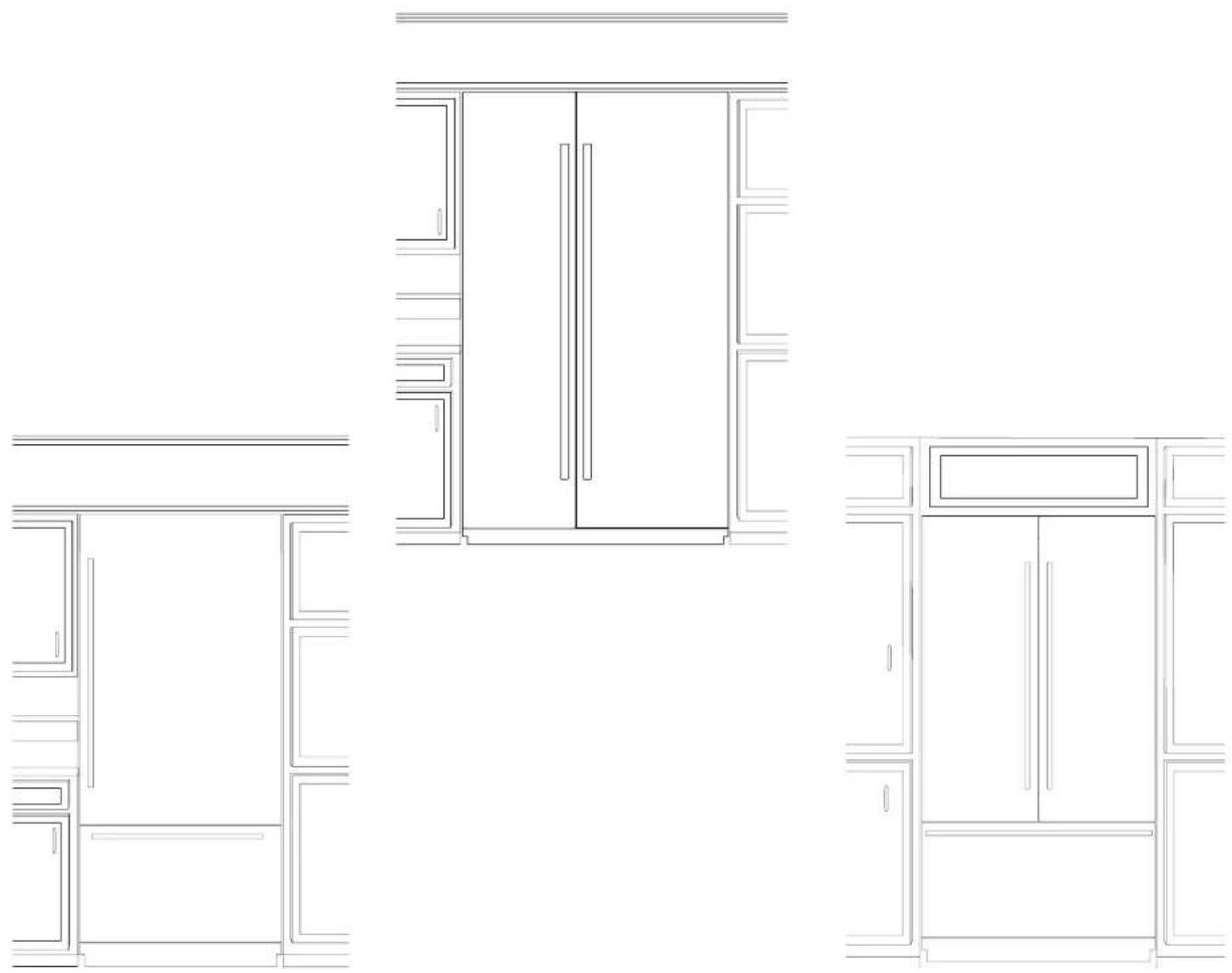
The Armoire-Style Door Panel Kit for fully integrated JennAir® refrigerators enables door panels with a hidden top panel for the ultimate integrated design in kitchen cabinet.
IMPORTANT:
These instructions are intended as a general guide only and do not supersede any national or local codes in any way. Compliance with all local, state, or national codes pertaining to this type of installation should be determined prior to installation.
■ These instructions are intended to supplement the Installation Instructions provided with your refrigerator, not replace them. Follow the instructions provided with the refrigerator to install it into the cabinet.
NOTE: The hardware bag contains all the parts and fasteners needed to install panels. A hardware bag is shipped with the refrigerator. You will find the hardware bag in either one of the crisper drawers or attached to the outside of one of the refrigerator doors.
CAUTION
Pinch Hazard
Installation of door panels with less than a 38 " (0.95 cm) gap between the door panel and the adjacent cabinet increases the risk of potential pinching.
TOOLS AND PARTS REQUIRED
Assemble the required tools and parts before starting installation. Read and follow the instructions provided with any of the required tools listed here. Proper installation is your responsibility.
Tools Required:
■ Cordless drill and drill bits
■ 3/8" and 1/2" Open-end wrenches or two adjustable wrenches
Phillips screwdriver
■ Small level
■ Appliance dolly
■ 3/32", 5/32", and 3/16" Hex keys
■ 1/4" and 5/16" Nut drivers
■ 6" Extension nut drivers
■ Tape measure
TOOLS AND PARTS PROVIDED
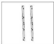
Parts Supplied with Panel Kit:
Grille Panel
W11215146 (for 36" models) W11215148 (for 42" models) W11215150 (for 48" models)
Grille bracket assembly W11215152 (RH side) W11215154 (LH side)
Foam air divider
W11239303
SITE PREPARATION BEFORE INSTALLATION (CONTD.)
Parts Supplied with Refrigerator (Needed for Armoire Installation):
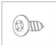
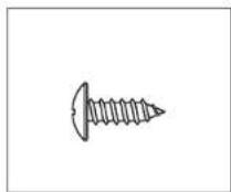
Phillips-head flat screw Black: 8281252
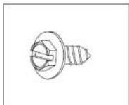
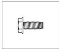
Slotted hex-head screw W10141645
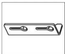
Door stop pin W10234202
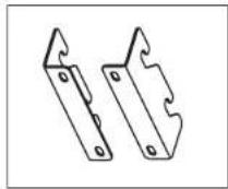
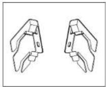
Panel top brackets Black: W10667450
Freezer panel brackets W10606815

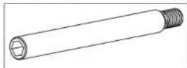
Shoulder washer W10471946
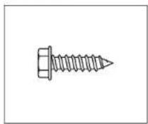
Hex-head pointed screw W10141189
6 | SITE PREPARATION
All hardware
■ Hinge cover trim (RC and FC)
Side trim
■ Handle side door trim
■ Installation block
■ Panel templates
PARTS SUPPLIED WITH REFRIGERATOR
The following parts are either not needed to install the panels in this kit, or they are already installed on the panels. These parts can be discarded after the installation is completed:
Standard grille bracket W10182743 (left) W10172741 (right)
Integrated grille bracket W10260890 (left) W10260891 (right)
Round-head screw 1163283
Hex-head blunt screw W10142233
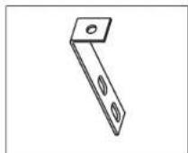
"L" brackets W10234199
SITE PREPARATION INSTALLATION REQUIREMENTS
PLAN THE INSTALLATION
IMPORTANT:
■Install the handles on the panels prior to panel installation. Follow the instructions received with handle kit to install the handles.
■Plan your installation using these instructions in conjunction with the Installation Instructions provided with the refrigerator. Modifications must be made to the refrigerator to accommodate the Armoire-style door panels.
Required parts
■ One of the following built-in refrigerator models:
42° Side-by-Side: JBSFS42NMX
48" Side-by-Side: JBSFS48NMX
36" Bottom Mount: JB36NXFXLE, JB36NXFXRE
36" French Door Bottom Mount: JF36NXFXDE
42" French Door Bottom Mount: JF42NXFXDE
■ Accessory Armoire-Style Door Panel Kit which includes (Grille Assembly and Grille Bracket Assembly)
■ Custom Panels
NOTE: The required thickness for all panels is 3/4" (1.91 cm).
OPENING REQUIREMENTS
IMPORTANT:
■ The width of the opening, from side to side, must be as specified for your model, for at least 3" (7.62 cm) back from the face of the cabinet. If your opening does not meet this requirement, you will need to make modifications.
■ The depth of the opening from the front of the cabinet to the back wall must be 25" (63.5 cm) minimum to achieve a flush installation.
CABINET AND PANEL INSTALLATION OPTIONS
Cabinet Depth - 25" (63.5 cm)
Grille Bracket - Top View
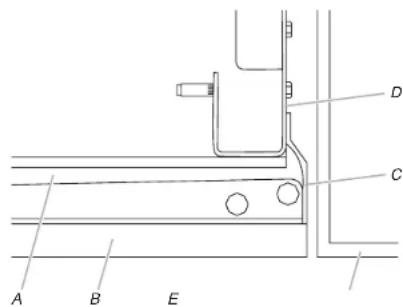
A. Refrigerator door B. Armoire-style door panel
C. Side trim
D. Grille bracket
E. Adjacent cabinet
Grille Bracket - Side View
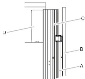
A. Refrigerator door
B. Armoire-style door panel
C. Side trim
D. Grille bracket
SITE PREPARATION CABINET CUTOUT OPTIONS
AIRFLOW VENTING RECOMMENDATIONS
IMPORTANT:
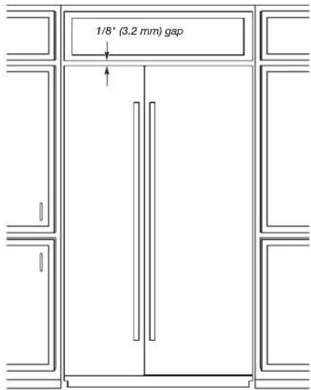
■ Armoire-style installations recommends a minimum of 1/8" (3.2 mm) of open space above the refrigerator. It is recommended that this space not be blocked in any way, including soffits.
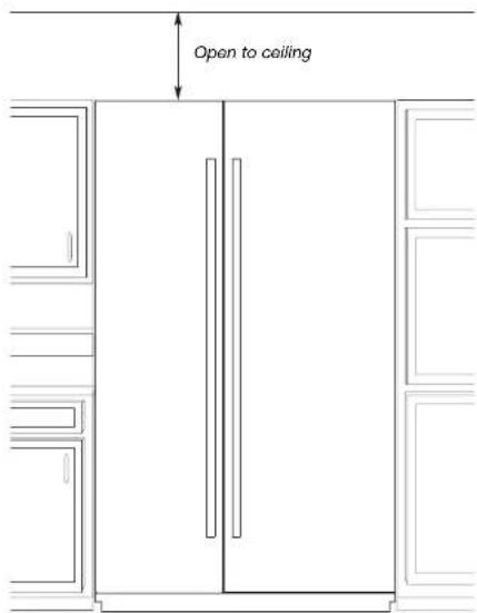
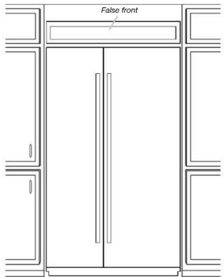
■ Models may be installed using either Option 1, Option 2 or option 3.
Option 1 - Open to Ceiling
Option 2 - False Front (cabinet face only) Option 3 - Closed Soffit
SITE PREPARATION PANEL DIMENSIONS
BOTTOM MOUNT MODEL
! Maximum allowable weights: • Door panel - 60 lbs (27.2 kg) • Drawer panel - 25 lbs (11.3 kg)
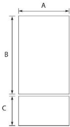
| Legend Model Dimension | |
| A 36" 35 | 34" (90.81 cm) |
| B 36" 59 | 16" (150.2 cm) |
| C 36" 20 | 12" (52.07 cm) |
FRENCH DOOR BOTTOM MOUNT MODELS
! Maximum allowable weights:
• Door panel - 38 lbs (17.2 kg)
- Drawer panel (36" model) - 25 lbs (11.3 kg)
- Drawer panel (42" model) - 30 lbs (13.6 kg)
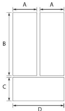
| Legend Model Dimension | ||
| A | 36" | 17 34 " (45.24 cm) |
| B 59 | 18 " (150.2 cm) | |
| C 20 | 12 " (52.07 cm) | |
| D 35 | 34 " (90.81 cm) | |
| A | 42" | 20 34 " (52.86 cm) |
| B 59 | 18 " (150.2 cm) | |
| C 20 | 12 " (52.07 cm) | |
| D 41 | 34 " (106.05 cm) | |
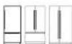
SIDE BY SIDE MODELS
! Maximum allowable weights (42" models):
• Refrigerator Door panel - 65 lbs (29.5 kg)
• Freezer Door panel - 49 lbs (22.2 kg)
Maximum allowable weights (48" models):
• Refrigerator Door panel - 66 lbs (29.9 kg)
• Freezer Door panel - 50 lbs (23 kg)
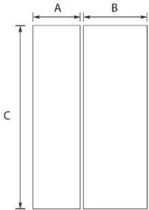
| Legend Model Dimension | ||
| A | 42" | 17 ^3 /4"(45.24 cm) |
| B 23 | ^3 /4"(60.48 cm) | |
| C 81"(205.7 cm) | ||
| A | 48" | 20 ^1 /4"(51.59 cm) |
| B 27 | ^1 /4"(69.37 cm) | |
| C 81"(205.7 cm) | ||
SITE PREPARATION SECONDARY ANTI-TIP BOARD
WARNING

Tip Over Hazard
Refrigerator is top heavy and tips easily when not completely installed.
Install secondary anti-tip board to ensure product stability.
Use two or more people to move and install refrigerator.
Failure to do so can result in death or serious injury.
IMPORTANT:
■ For all Armoire-style door panel installations, the secondary anti-tip board is required to be installed prior to door panel installation.
This anti-tip board is to be secured on the right side of the cabinet enclosure as per the dimensions shown in illustration.
NOTE: Anti-tip board is required as an addition to the rear wall anti-tip board (for open to ceiling installation) described in the installation instructions provided with the refrigerator.
- Secure the secondary anti-tip board so that the bottom surface of the secondary anti-tip board is 75^1/2 (191.77 cm) from the floor (right hand side).
■ The main anti-tip boards for open to ceiling installation are secured at 84" (213.36 cm) from the floor (rear side).
■ During panel installation, raise the refrigerator up until the top of the refrigerator is making contact with the bottom of the secondary anti-tip board.
INSTALLING THE SECONDARY ANTI-TIP BOARD
- Mark the stud locations on right hand side cabinet wall.
- Securely attach one 2" x 4" x 12" (5 cm x 10 cm x 30.4 cm) board to the cabinet on right hand side cabinet using wood screws. Use three #8 x 2" (5.08 cm) (or longer) wood screws.
NOTE:
■ It is recommended to drive the wood screws from cabinet wall into the secondary anti-tip board as shown in the illustration.
■ The board must have overlap of 1" (2.54 cm) with the refrigerator top.
■ Leave 4" (10.16 cm) free space at rear as shown in the illustration.
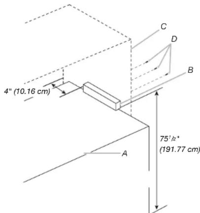
A. Refrigerator
C. Kitchen cabinet
B. Secondary anti-tip board
D. Wood screws
INSTALLATION
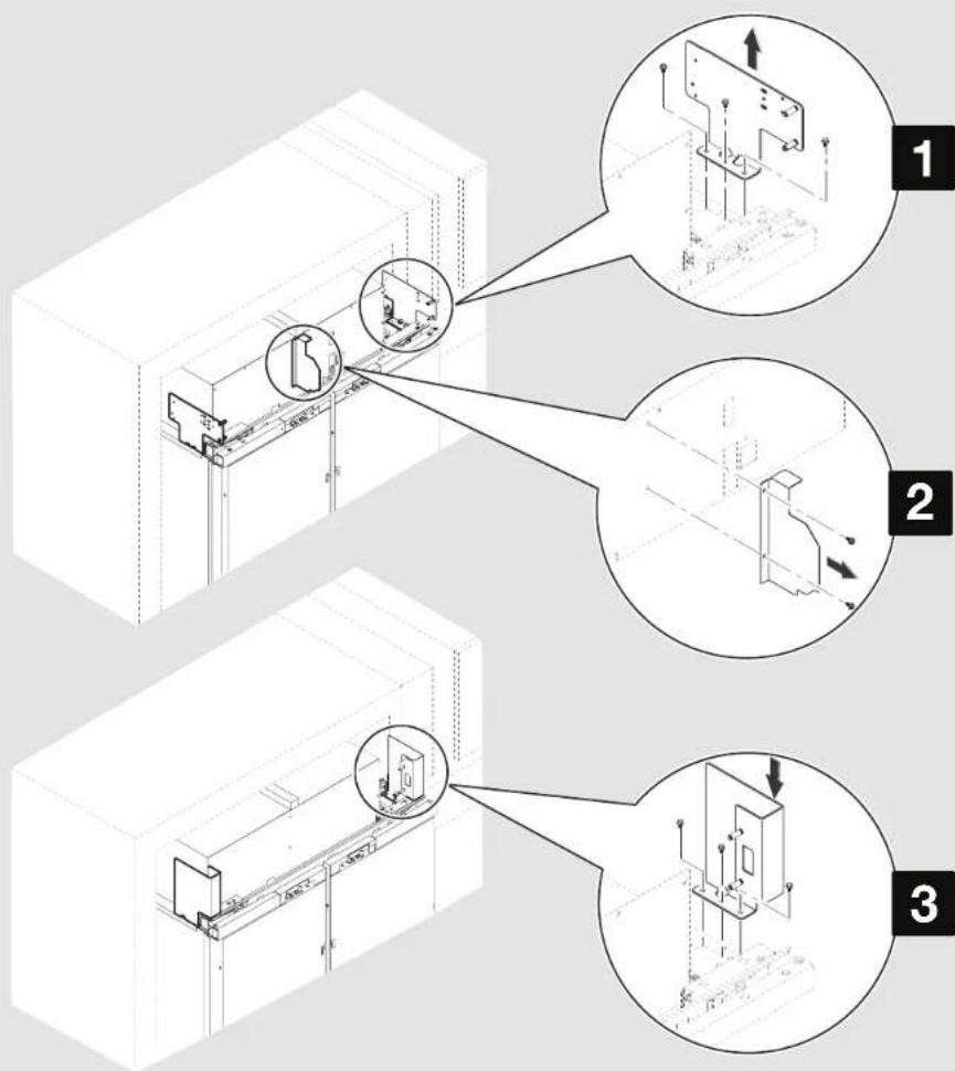
INSTALLING GRILLE BRACKET ASSEMBLY
APPLIES TO:

WARNING
Excessive Weight Hazard
Use two or more people to move and install refrigerator.
Failure to do so can result in back or other injury.
NOTE: If refrigerator is not on rollers, it is recommended to lower the product to have more access at the top of product for panel installation. For ease of grille installation, it is recommended to have product outside of kitchen cabinet not more than 8" (20.32 cm).
- Remove the three screws fastening each mounting plate to the top of the refrigerator on each side. Discard the mounting plates but keep the screws for attaching the two grille bracket assemblies provided in this kit.
- Remove the two screws fastening the air divider to the unit housing. Discard the air divider, and reinstall the screws into the holes from where they were removed.
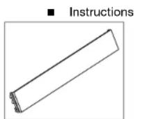
- Align the three holes in a grille bracket assembly with the three holes in a cabinet side, as shown. Using the screws removed in Step 1, attach the grille bracket assembly.
- Repeat step 3 to install the other grille bracket assembly to the opposite side of the refrigerator. IMPORTANT: Installing the Armoire-style door panels before removing both existing factory installed grille brackets can damage the panels.
Parts to be used:
X2 Grille bracket assembly
INSTALLATION | 11
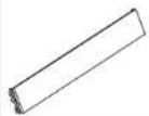
INSTALLATION INSTALLING AIR DIVIDER
Align the base of foam air divider with base of unit housing!
APPLIES TO:
- Peel away the paper layer from the foam air divider to reveal the adhesive side.
- Stick the foam air divider to unit housing at the location where metallic air divider was installed earlier by applying even pressure.
| Parts to be used: | |
| [DTST] | X1 Foam air divider |
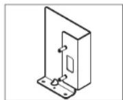
INSTALLATION INSTALLING GRILLE PANEL
APPLIES TO:
- Position the grille panel between the grille brackets on each side of the cabinet.
- Hook the top of grille onto the upper rivet pins. Rotate downward and push the bottom of the grille panel in until the grille panel snaps into place.
NOTE: For grille panel removal, push the top of grille panel inward until the lower portion snaps out. Rotate and lift off the grille panel.
| Parts to be used: | |
 | X1 Grille panel |
INSTALLATION
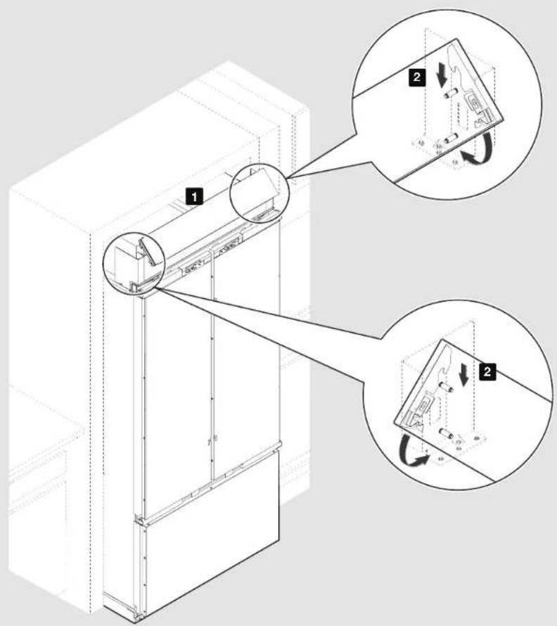
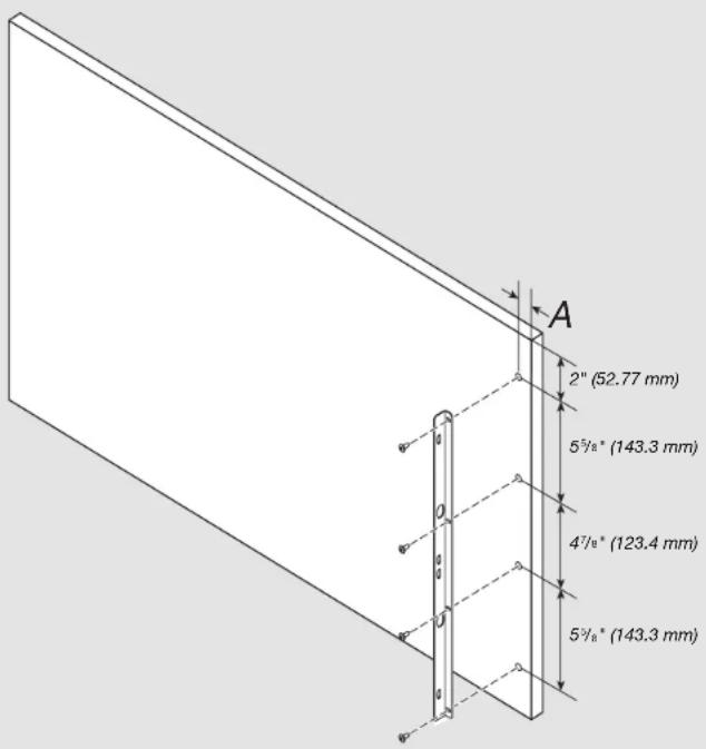
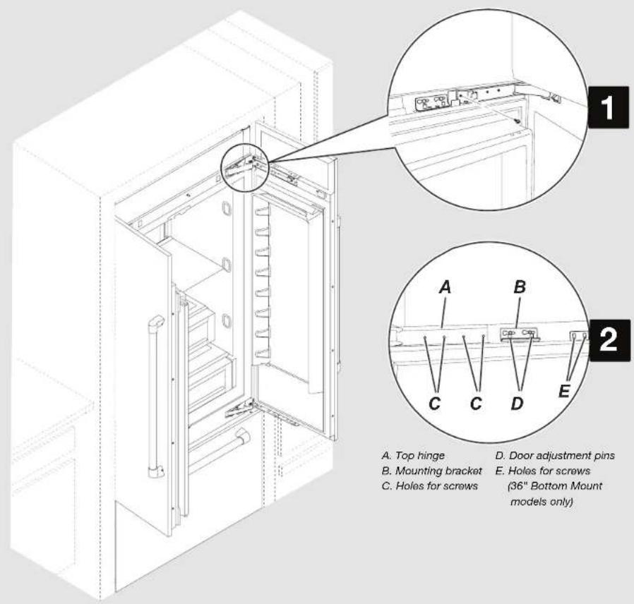
MARKING DOOR PANEL TOP BRACKET LOCATION(S)
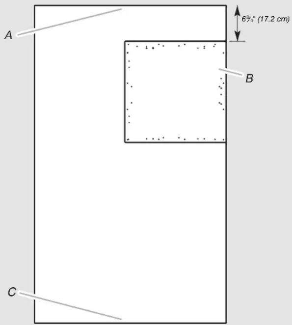
A. Top of custom refrigerator door panel
B. Drilling template
C. Bottom of custom refrigerator door panel
APPLIES TO:
IMPORTANT: For an Armoire installation, instead of drilling holes along the top edge(s) of the custom door panel(s), you must adjust the placement of the drilling template (provided with the refrigerator).
NOTES:
■No template adjustment is needed for the bottom edge of the door panel(s).
■No template adjustment is needed for the custom freezer drawer panel.
- Align the drilling template on the back of the custom refrigerator door panel so that the top of the template is offset 6 ^3/4 " (17.2 cm) from the top of the refrigerator door panel.
NOTE: The only offset dimension is the 6¾" (17.2 cm) offset from the top of the door panel.
- Continue to use the template as you normally would along the bottom, handle side of the door panel.
INSTALLATION
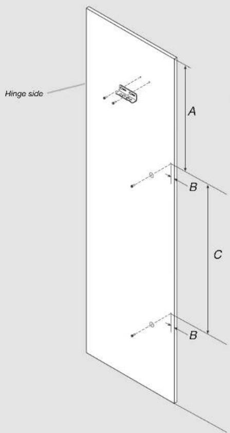
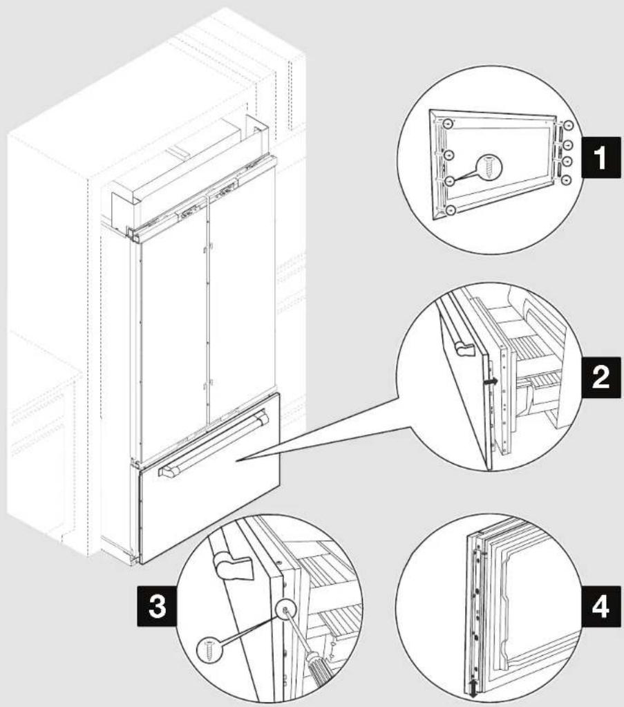
INSTALLING PANEL TOP BRACKET(S) AND SHOULDER WASHERS
APPLIES TO:
- Fasten the refrigerator/freezer door panel top bracket to custom wood door panel using hex-head pointed screws (2) at marked screw locations (refer "Marking Door Panel Top Bracket Location(s)" section).
- For marking location of the shoulder washers, Measure 'A' from the top of the panel, measure 'B' from side of panel. Mark the hole locations as shown in Figure. Refer Table 1 for 'A', 'B', and 'C' dimension based on the models.
- Fasten the shoulder washer to custom wood door panel using hex-head pointed screws (2) at marked screw locations in Step 2. NOTE: Do not drive the screws completely, allowing clearance so that shoulder washer can be inserted into J slot located on door.
- In case of French door bottom mount and side by side models, repeat Steps 1-3 for installing panel brackets and shoulder washers on other door.
Table 1 - Shoulder washer locations
| Model 'A' | 'B' 'C' | ||
| 36" Bottom Mount | 18 ^5 / _16 " (465.5 mm) | 1 ^3 / _16 " (30.3 mm) | 30 ^1 / _2 " (774 mm) |
| 36" / 42" French Door | 18 ^5 / _16 " (465.5 mm) | 7/8" (21.75 mm) | 30 ^1 / _2 " (774 mm) |
| 42" / 48" Side by Side | 23" (583.5 mm) | 13/16" (20.6 mm) | 42 ^5 / _16 " (1075 mm) |
INSTALLATION
INSTALLING FREEZER BRACKETS
FOR SIDE BY SIDE MODELS - SKIP THIS STEP!
APPLIES TO:

- For marking location of the freezer bracket screws, Measure 'A' from the top of the panel. Mark the hole locations as shown in Figure. Refer to Table 2 for 'A' dimension based on the models.
- Fasten the freezer bracket to custom wood drawer panel at marked screw locations in step 1.
- Repeat step 1-2 to attach freezer bracket on other side.
Table 2 - Freezer bracket locations
| Model ‘A’ | |
| 36" Bottom Mount / French Door | 1/2"(12.85 mm) |
| 42" French Door | 9/16"(14.43 mm) |
INSTALLATION
INSTALLING FREEZER PANEL
FOR SIDE BY SIDE MODELS - SKIP THIS STEP!
APPLIES TO:

- Slightly loosen the bracket screws present on freezer panel.
NOTE: Be sure that the refrigerator door(s) are tightly closed. - Slide panel onto drawer. Retighten the four screws on each side attaching the bracket to the drawer panel.
- Using the Phillips-head flat screws, fasten the panel brackets to the drawer.
- To allow for later adjustment of the panel, do not fully tighten the screws attaching the bracket to the drawer.
IMPORTANT: When you have completed installing all the panels, check for alignment. The drawer panel will move up or down to align. Completely tighten the screws only when panels are fully aligned.
Parts to be used:
| X6 Phillips-head screws |
INSTALLATION
INSTALLING DOOR PANEL(S)
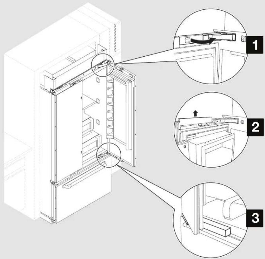
APPLIES TO:
WARNING

Tip Over Hazard
Refrigerator is top heavy and tips easily when not completely installed.
Install secondary anti-tip board to ensure product stability.
Use two or more people to move and install refrigerator.
Failure to do so can result in death or serious injury.
NOTE:
-
Be sure that secondary anti-tip board is installed before opening the door. Refer "INSTALLING THE SECONDARY ANTI-TIP BOARD" section to install the secondary anti-tip board.
For panel installation, it is recommended to have product outside of kitchen cabinet not more than 8" (20.32 cm).
■ Raise the refrigerator until the top of the refrigerator touches the bottom of secondary anti-tip board.
■ Open only one door at a time. -
Open the door(s) and remove the hinge cover(s). NOTE: French door and bottom mount models have bottom hinge cover(s) that also must be removed.
- Take out the door adjustment pin cover(s) to expose the adjustment pins.
- Use foam packaging to prop and hold the door open while installing a door panel.
INSTALLATION
INSTALLING DOOR PANEL(S) (CONTD.)
WARNING
Excessive Weight Hazard
Use two or more people to move and install panels.
Failure to do so can result in back or other injury.
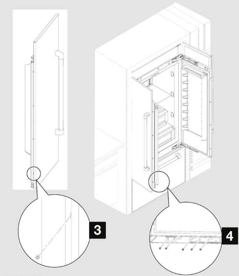
- Align the two shoulder washers, on the back of the door panel, with the "J" slots on the side of the refrigerator door.
- Simultaneously slide the panel onto the door, and lower the panel bracket down onto the adjustment pins at the top of the door.
NOTE:
■ On French door and side by side models, repeat steps 2 through 5 to install the second door panel.
■ After panel(s) are installed properly, lower the refrigerator onto the rollers.
INSTALLATION
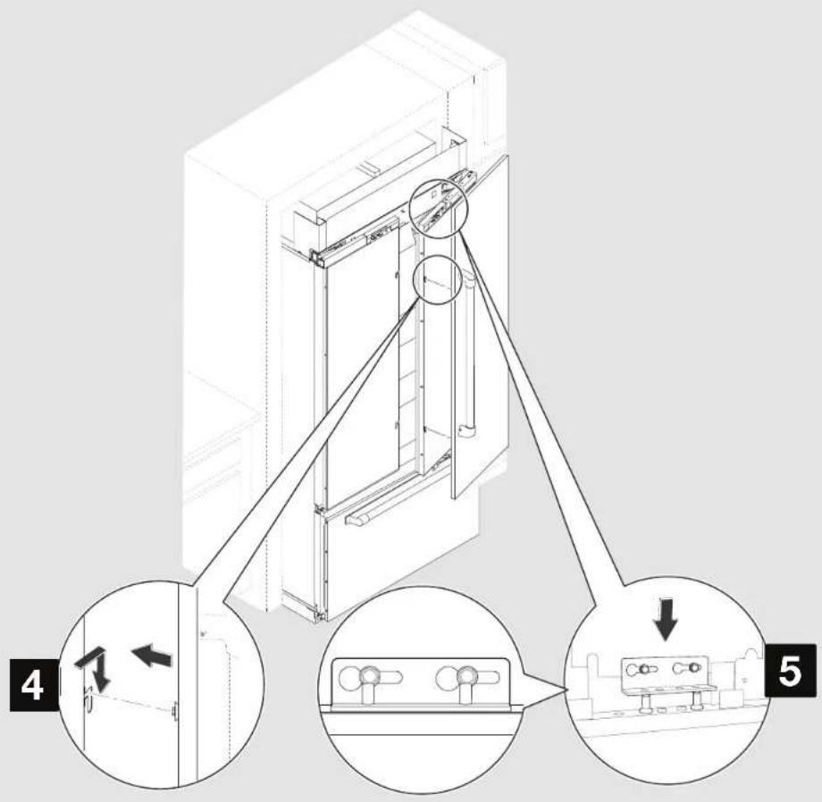
MOVING REFRIGERATOR TO FINAL POSITION
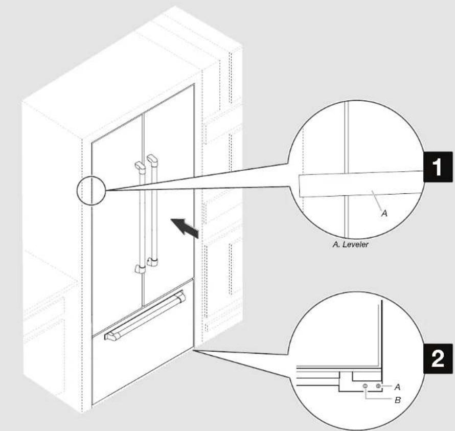
20 | INSTALLATION
A. Rear leveling bolt B. Front leveling bolt
APPLIES TO:
WARNING
Excessive Weight Hazard
Use two or more people to move and install refrigerator.
Failure to do so can result in back or other injury.
- Move the refrigerator straight back and evenly into the cabinet opening so that all the panels are flush with adjacent cabinets from all sides.
- Use a 5/16" Nut driver to turn the leveling bolts clockwise to raise the refrigerator. Adjust the leveling bolts until the top of the refrigerator is making contact with the bottom of the secondary anti-tip board.
IMPORTANT: After height adjustment, ensure refrigerator is perfectly leveled horizontally. And ensure panels are flush with adjacent cabinets.
INSTALLATION
ADJUSTING DOOR SWING
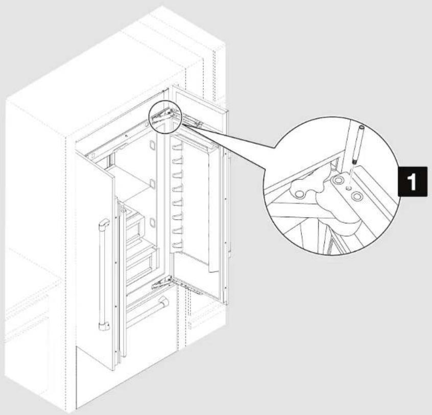
natural_image
Technical line drawing of an open industrial cabinet with a magnified inset showing internal components (no text or symbols)APPLIES TO:

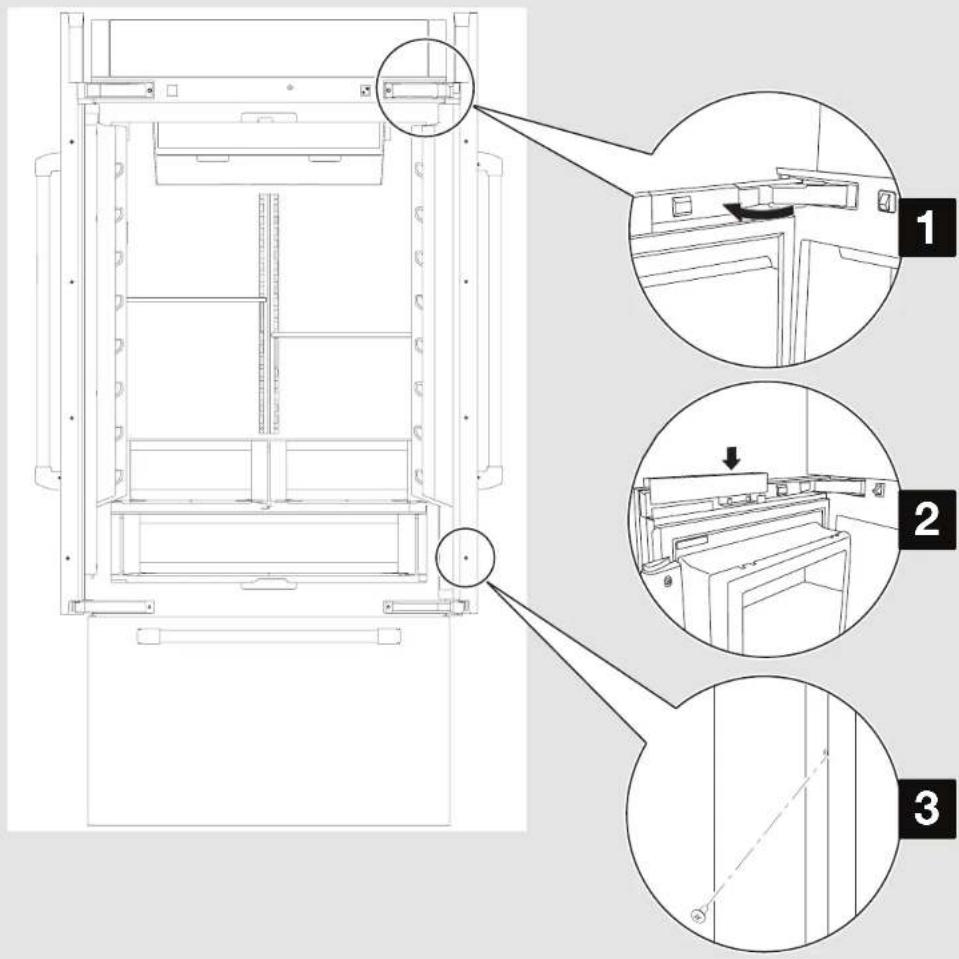
- If the standard 110° door swing is too wide, install the door stop pin to allow for a maximum 90° door swing. Insert the door stop pin into the top hinge in the hole shown. Use a 5/32" hex key, to tighten door stop pin.
| Parts to be used: | |
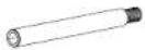 | Door stop pin (as required) |
INSTALLATION ADJUSTING FREEZER PANEL
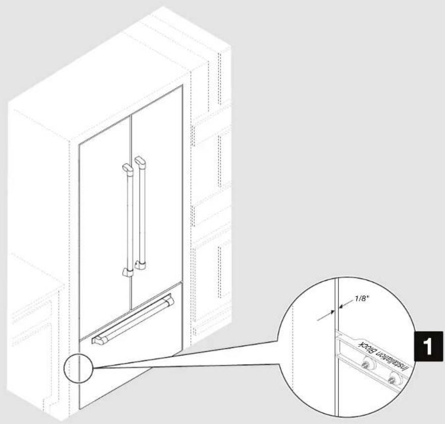
22 | INSTALLATION
FOR SIDE BY SIDE MODELS - SKIP THIS STEP!
APPLIES TO:

- A 1/8" (3.2 mm) gap is required between the panel and adjacent cabinets. Use the installation block to measure the gaps.
INSTALLATION
ADJUSTING REFRIGERATOR PANEL(S)
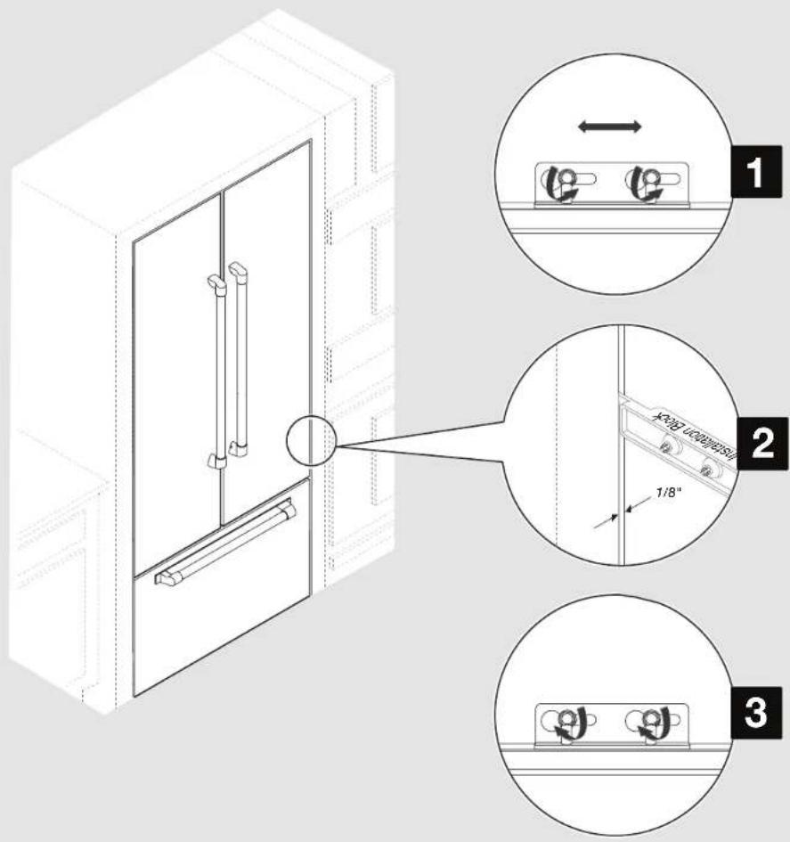
APPLIES TO:
-
Slightly loosen the panel bracket screws to allow the panel to move to the left or right.
-
Adjust panels to achieve a 1/8" (3.2 mm) gap between panels and adjacent cabinets. For French door bottom mount and bottom mount models, align the outside edge of the refrigerator panel to the outside edge of the freezer panel on both the sides. For side by side models, align the refrigerator and freezer panels with adjacent cabinets.
NOTE: Adjust the panel not the door, if adjustments are needed to achieve alignment or required spacing.
- Tighten the panel bracket screws.
INSTALLATION
ADJUSTING REFRIGERATOR PANEL(S) (CONTD.)
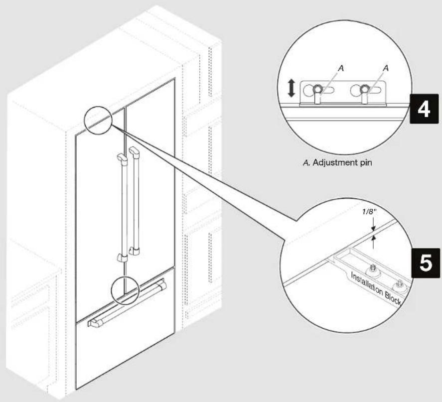
APPLIES TO:
- Use a 5/32" hex key to raise or lower the adjustment pins which allows the panel to move up or down.
- A 1/8" (3.2 mm) space is required between panel(s) and bottom of the soffit.
INSTALLATION
ATTACHING PANEL(S)
APPLIES TO:

- Using the slotted hex-head screws, fasten the top and bottom hinges to the door panels. Fully tighten all door panel screws.
NOTE: Do not overtighten the screws, it may strip the panel. - 36" Bottom Mount models only - Use the hex head screws to fasten the panel to the additional door bracket.
| Parts to be used: | |
 | Slotted hex-head screws(As required) |
INSTALLATION ATTACHING PANEL(S) (CONTD.)
26 | INSTALLATION
- Use the Phillips-head screws to fasten the panel to the door on vertical hinge side.
- Use slotted hex-head screws to attach the mounting bracket located at the bottom of the doors, to the door panels.
| Parts to be used: | |
 | Phillips-head screws(As required) |
 | Slotted hex-head screws(As required) |
INSTALLATION
COMPLETING THE INSTALLATION
APPLIES TO:

- Reinstall hinge cover(s).
- Snap the door adjustment pin cover(s) into place.
- Using the Phillips-head screws, attach the handle side trim pieces (shipped with the refrigerator) to the doors.
| Parts to be used: | |
 | Phillips-head screws(As required) |
ENSEMBLE DE PANNEAUX DE PORTE DE STYLE ARMOIRE POUR RÉFRIGÉRATEUR ENCASTRÉ
INTRODUCTION SÉCURITÉ
INSTALLATION POUR :

AVERTISSEMENT
1
INSTALLATION POUR :
1
POUR LES MODÈLES CÔTE À CÔTE – PASSER CETTE ÉTAPE

INSTALLATION POUR :
INSTALLATION POUR :
AVERTISSEMENT

AVERTISSEMENT
natural_image
Technical line drawing of an open industrial cabinet with a magnified inset showing internal components (no text or symbols)INSTALLATION POUR :

POUR LES MODÈLES CÔTE À CÔTE – PASSER CETTE ÉTAPE
INSTALLATION POUR :

INSTALLATION POUR :
52 | INSTALLATION
INSTALLATION POUR :


- INTRODUCTION
- SAFETY
- Your safety and the safety of others are very important.
- DANGER
- WARNING
- TABLE OF CONTENTS
- SITE PREPARATION
- INSTALLATION
- REGISTRATION
- REGISTERING YOUR PRODUCT
- PRODUCT IDENTIFICATION
- SITE PREPARATION BEFORE INSTALLATION
- IMPORTANT:
- CAUTION
- Pinch Hazard
- TOOLS AND PARTS REQUIRED
- Tools Required:
- TOOLS AND PARTS PROVIDED
- SITE PREPARATION BEFORE INSTALLATION (CONTD.)
- PARTS SUPPLIED WITH REFRIGERATOR
- SITE PREPARATION INSTALLATION REQUIREMENTS
- PLAN THE INSTALLATION
- Required parts
- OPENING REQUIREMENTS
- CABINET AND PANEL INSTALLATION OPTIONS
- SITE PREPARATION CABINET CUTOUT OPTIONS
- SITE PREPARATION PANEL DIMENSIONS
- FRENCH DOOR BOTTOM MOUNT MODELS
- SIDE BY SIDE MODELS
- SITE PREPARATION SECONDARY ANTI-TIP BOARD
- INSTALLING THE SECONDARY ANTI-TIP BOARD
- NOTE:
- INSTALLING GRILLE BRACKET ASSEMBLY
- INSTALLATION INSTALLING AIR DIVIDER
- APPLIES TO:
- INSTALLATION INSTALLING GRILLE PANEL
- MARKING DOOR PANEL TOP BRACKET LOCATION(S)
- NOTES:
- INSTALLING PANEL TOP BRACKET(S) AND SHOULDER WASHERS
- INSTALLING FREEZER BRACKETS
- FOR SIDE BY SIDE MODELS - SKIP THIS STEP!
- Tip Over Hazard
- INSTALLING DOOR PANEL(S) (CONTD.)
- Excessive Weight Hazard
- MOVING REFRIGERATOR TO FINAL POSITION
- ADJUSTING DOOR SWING
- INSTALLATION ADJUSTING FREEZER PANEL
- ADJUSTING REFRIGERATOR PANEL(S)
- ADJUSTING REFRIGERATOR PANEL(S) (CONTD.)
- INSTALLATION ATTACHING PANEL(S) (CONTD.)
- COMPLETING THE INSTALLATION
- ENSEMBLE DE PANNEAUX DE PORTE DE STYLE ARMOIRE POUR RÉFRIGÉRATEUR ENCASTRÉ
- INTRODUCTION SÉCURITÉ
- INSTALLATION POUR :
- AVERTISSEMENT
Brand : JENN-AIR
Model : W10663564
Category : Refrigerator