
JKRPR151HM - Refrigerator JENN-AIR - Free user manual and instructions
Find the device manual for free JKRPR151HM JENN-AIR in PDF.
| Product type | Built-in ice maker |
| Brand | JENN-AIR |
| Model | JKRPR151HM |
| Product width | 37.8 cm (14 15/16 in) |
| Product height | 85.7 cm (33 3/4 in) |
| Product depth (without door) | 56.1 cm (22 1/16 in) |
| Appliance weight (estimated) | Approximately 45 kg (100 lb) empty |
| Electrical supply | 115 V AC, 60 Hz, 15-20 A, 3-prong grounded outlet |
| Required water pressure | 207 to 827 kPa (30 to 120 lb/in²) |
| Ice production capacity | Not specified in manual |
| Storage bin capacity | Not specified in manual |
| Drain type | Gravity or pump (pump optional, part 1901A) |
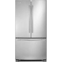
| Exterior material | Stainless steel (custom wood panel possible) |
| Care and cleaning | Clean interior before use with warm water and mild soap. Avoid abrasive cleaners and bleach on stainless steel. |
| Important safety instructions | Grounding required, do not use extension cord, disconnect power before servicing. Beware of crushing hazards when handling hinges. |
| Available replacement parts | Drain pump (1901A), insulating sleeve (W10365792), stainless steel panel, handle, water supply line (8003RP or W10505928RP) |
| Recommended ambient temperature | 13°C to 43°C (55°F to 110°F), optimal between 21°C and 32°C |
| Installation | Built-in, requires opening 38.1 cm wide, 86.4-87.6 cm high, 61 cm deep. Use at least two people to move. |
| Water supply | Connect to a potable water source only, 1/4 in OD copper tubing. |
Frequently Asked Questions - JKRPR151HM JENN-AIR
User questions about JKRPR151HM JENN-AIR
0 question about this device. Answer the ones you know or ask your own.
Ask a new question about this device
Download the instructions for your Refrigerator in PDF format for free! Find your manual JKRPR151HM - JENN-AIR and take your electronic device back in hand. On this page are published all the documents necessary for the use of your device. JKRPR151HM by JENN-AIR.
USER MANUAL JKRPR151HM JENN-AIR
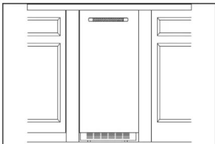
natural_image
Technical line drawing of a refrigerator interior layout (no text or symbols)
JENNAIR®

natural_image
Abstract geometric design with a large white number '4' and the letters 'TM' on a dark, glossy surface (no readable text or symbols beyond the graphic elements)INTRODUCTION
SAFETY
Your safety and the safety of others are very important.
We have provided many important safety messages in this manual and on your appliance. Always read and obey all safety messages.

This is the safety alert symbol.
This symbol alerts you to potential hazards that can kill or hurt you and others.
All safety messages will follow the safety alert symbol and either the word "DANGER" or "WARNING."
These words mean:
DANGER
You can be killed or seriously injured if you don't immediately follow instructions.
WARNING
You can be killed or seriously injured if you don't follow instructions.
All safety messages will tell you what the potential hazard is, tell you how to reduce the chance of injury, and tell you what can happen if the instructions are not followed.
IMPORTANT SAFETY INSTRUCTIONS
WARNING: To reduce the risk of fire, electric shock, or injury when using your refrigerator, follow these basic precautions:
■ Plug into a grounded 3 prong outlet.
■ Do not remove ground prong.
■ Do not use an adapter.
■ Do not use an extension cord.
■ Do not store explosive substances such as aerosol cans with a flammable propellant in this appliance.
■ Disconnect power before cleaning.
■ Disconnect power before servicing.
■ Replace all parts and panels before operating.
■ Connect to potable water supply only.
■ If the supply cord is damaged, it must be replaced by the manufacturer, its service agent, or similarly qualified person in order to avoid a hazard.
■ This appliance is not intended for use by persons (including children) with reduced physical, sensory, or mental capabilities, or lack of experience and knowledge, unless they have been given supervision or instruction concerning use of the appliance by a person responsible for their safety.
■ Use two or more people to move and install ice maker.
■ Children should be supervised to ensure that they do not play with the appliance.
■ This appliance is intended to be used in household and similar applications such as:
– staff kitchen areas in shops, offices, and other working environments;
– farmhouses and by clients in hotels, motels, and other residential-type environments;
- bed and breakfast-type environments;
- catering and similar non-retail applications.
SAVE THESE INSTRUCTIONS
INTRODUCTION
REGISTERING YOUR APPLIANCE
Gain access to our concierge-level customer support by registering your appliance. We make product registration simple and straightforward so that you can start using your exclusive JennAir benefits today.
Registering your appliance allows you to:
■Streamline your warranty service
If we have your product information, we can help you faster.
■Protect your purchase
In case of an insurance loss—such as fire, flood, or theft—your product registration could serve as a proof of purchase.
■Keep your family safe
We'll notify you in the rare case of a safety notification.
Start taking advantage of these benefits today by going online to register your product at jennair.com/customer-care.
PRODUCT IDENTIFICATION
Your product identification, which includes the model and serial number, is listed on the product rating plate.
Recording this information below allows us to more easily assist you if your product should ever require service from one of our Whirlpool Authorized Service Providers.
Model Number: ____
Serial Number:
Date of Installation: ____
Authorized Dealer: ____
Authorized Dealer Phone #: ____
TABLE OF CONTENTS
INTRODUCTION
Safety 3
Registering Your Appliance 4
Product Identification 4
GETTING STARTED
Before installation....5
Tools Required....5
Parts Provided 5
Vacation or Extended Time
Without Use....6
Unpack the Ice Maker 6
Optional Personalizations......6
SITE PREPARATION
Product and
Opening Dimensions....7
Location Requirements......8
Electrical Requirements....9
Water Supply Requirements......10
Drain Supply Requirements....11
Gravity Drain System 11
Drain Pump System....11
DOOR REVERSAL
Removing Hinge Covers....12
Removing the Hinges....14
Preparing the Bottom Hinges.... 18
Reversing the Hinges....20
INSTALLATION
Installing the Drain Pump -
Site Preparation....22
If Ice Maker is Currently Installed .....22
Installing the Drain Pump
and Drain Hose....24
Connecting the Water supply 28
Leveling and Securing....30
Custom Wood Door Panel 34
Connecting the Drain 36
Installing Auxiliary Grill....38
APPENDIX
Accessories 40
TABLE DES MATIÈRES......44
GETTING STARTED
BEFORE INSTALLATION
Gather the required tools and parts before starting installation. Read and follow the instructions provided with any tools listed.
IMPORTANT: These instructions are intended as a general guide only and do not supersede any national or local codes in any way. Compliance with all local, state, or national codes pertaining to this type of installation should be determined prior to installation.
Installer: Please be sure to leave Installation Instructions with the homeowner.
Homeowner: Keep the Installation Instructions for future reference.
TOOLS REQUIRED
Gather the required tools before starting installation.
TOOLS REQUIRED
- Drill and drill bits
■ Phillips screwdriver
■ Pencil
■ Masking tape
■ Two adjustable wrenches
Level
■ Wood screws
■ 2" Hole saw or 2" Forstner bit
■ 3/16" hex driver
■ 1/4" nut driver
Pliers
■ Right angle drivers
■ TORX T20, T25crewdriver
■ Tape measure
PARTS PROVIDED
■ Cabinet brackets
■ Drain hose and clamp (in hose bag) - on some models only
■ #8 x 1/2" pan head wood screws (14)
■ Double sided adhesive tape (for custom door panel)
■ Auxiliary grill kit
GETTING STARTED
VACATION OR EXTENDED TIME WITHOUT USE
When you will not be using the ice maker for an extended period of time, turn off the water and power supply to the ice maker.
Check that the water supply lines are insulated against freezing conditions. Ice formations in the supply lines can increase water pressure and cause damage to your ice maker or home. Damage from freezing is not covered by the warranty.
Excessive Weight Hazard
Use two or more people to move and install ice maker.
Failure to do so can result in back or other injury.
REMOVING PACKAGING MATERIALS
Uncrate the ice maker. Remove tape and glue from your ice maker before using.
■ To remove any remaining tape or glue from the exterior of the ice maker, rub the area briskly with your thumb. Tape or glue residue can also be easily removed by rubbing a small amount of liquid dish soap over the adhesive with your fingers. Wipe with warm water and dry.
- Do not use sharp instruments, rubbing alcohol, flammable fluids, or abrasive cleaners to remove tape or glue. Do not use chlorine bleach on the stainless steel surfaces of the ice maker. These products can damage the surface of your ice maker.
CLEANING BEFORE USE
After you remove all of the packaging materials, clean the inside of your ice maker before using it. For instructions on how to clean the ice maker, refer to the cleaning instructions in the "Ice Maker Care" section of Use and Care Guide.
OPTIONAL PERSONALIZATIONS
REVERSING THE DOOR
For instructions on how to reverse the door, refer to the "Door Reversal" section.
CUSTOM PANEL INSTALLATION
For instructions on how to install a custom door panel, refer to the "Custom Wood Door Panel" section.
If you plan to install a custom overlay panel, you will need to make the panel yourself or consult a qualified cabinetmaker or carpenter.
IMPORTANT:
■ The thickness of the overlay panel must be 3/4" (1.91 cm).
■ Overlay panel must not weigh more than 8 lbs (3.62 kg).
■ Overlay panels weighing more than recommended may cause damage to your ice maker.
■ Countersink all the handle mounting hardware.
■ Match wood grain direction with that of adjacent cabinets.
■ Sand panel edges to provide a smooth finish.
■ Use moisture sealer on both sides and all edges of the panel to avoid damage from moisture.
PARTS NEEDED:
■ Instructions, #8 x 1/2" pan head wood screws (14)
■ Handle Kit (optional)
STAINLESS STEEL PANEL INSTALLATION
For instructions on how to install the Stainless Steel Panel, refer to the instructions received with the Stainless Steel Panel kit.
SITE PREPARATION
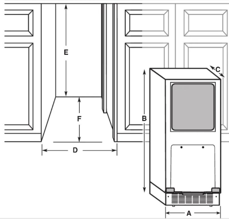
PRODUCT AND
OPENING DIMENSIONS
| Product Dimensions | ||
| Product width A | 14 | 78" (37.8 cm) |
| Product height B | 33 | 34" (85.7 cm) |
| Product depth(no door) | C | 22116" (56.1 cm) |
| Opening Dimensions | ||
| Opening width D | 15" | (38.1 cm) |
| Opening height E | 34" min (86.4 cm)34 12 " max (87.6 cm) | |
| Opening depth F | 24" | (60.96 cm) |
SITE PREPARATION
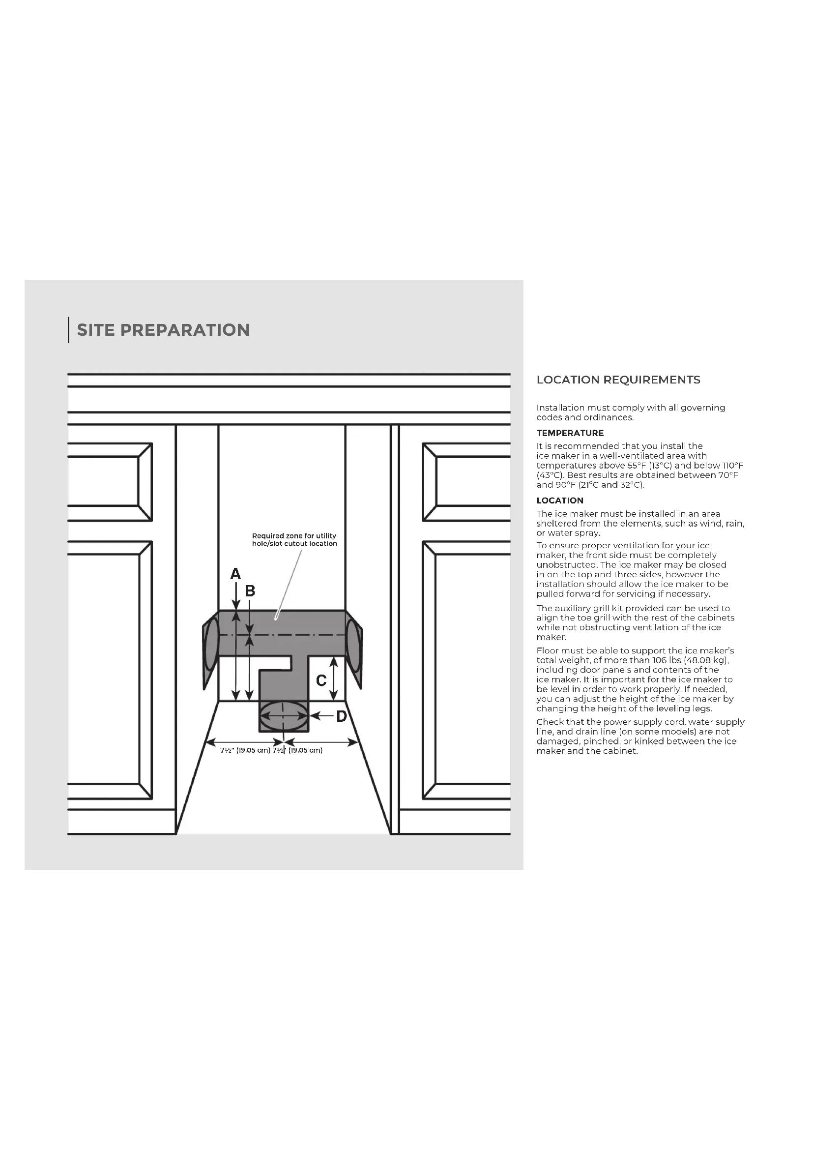
LOCATION REQUIREMENTS
Installation must comply with all governing codes and ordinances.
TEMPERATURE
It is recommended that you install the ice maker in a well-ventilated area with temperatures above 55^ F ( 13^ C) and below 110^ F ( 43^ C). Best results are obtained between 70^ F and 90^ F ( 21^ C and 32^ C).
LOCATION
The ice maker must be installed in an area sheltered from the elements, such as wind, rain, or water spray.
To ensure proper ventilation for your ice maker, the front side must be completely unobstructed. The ice maker may be closed in on the top and three sides, however the installation should allow the ice maker to be pulled forward for servicing if necessary.
The auxiliary grill kit provided can be used to align the toe grill with the rest of the cabinets while not obstructing ventilation of the ice maker.
Floor must be able to support the ice maker's total weight, of more than 106 lbs (48.08 kg), including door panels and contents of the ice maker. It is important for the ice maker to be level in order to work properly. If needed, you can adjust the height of the ice maker by changing the height of the leveling legs.
Check that the power supply cord, water supply line, and drain line (on some models) are not damaged, pinched, or kinked between the ice maker and the cabinet.
SITE PREPARATION
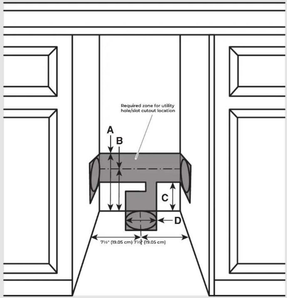
IMPORTANT:
This ice maker has been designed for flush install in instances where the power supply, water supply, and drain are located in a cabinetry.
■For installation of product with utilities behind the ice maker, flush install may not be achieved.
■Refer "Location Requirement" illustration and table below for utility slot/hole cutout location.
| Utility Slot/Cutout Location Zone | |
| Dimension | A 9" (22.9 cm) |
| B 8" (20.3 cm) | |
| C 7" (17.8 cm) | |
| Diameter of the hole D 2" (5 cm) | |
ELECTRICAL REQUIREMENTS
WARNING

Electrical Shock Hazard
Plug into a grounded 3 prong outlet.
Do not remove ground prong.
Do not use an adapter.
Do not use an extension cord.
Failure to follow these instructions can result in death, fire, or electrical shock.
| Electrical Requirements | |
| Power Supply 115 | V, 60Hz, AC only |
| Circuit Breaker 15 | to 20 A, fused |
| Receptacle 3 prong | g grounding-type |
| Outlet Non-GFCI | |
IMPORTANT:
■Use an outlet that cannot be turned off by a switch. Do not use an extension cord.
It is recommended that this product not be connected to a GFCI (Ground Fault Circuit Interrupter) protected outlet, as nuisance tripping of the power supply may occur.
■The ice maker must be grounded. The ice maker is equipped with a power supply cord having a grounded 3 prong plug. The cord must be plugged into a mating, grounded, 3 prong wall receptacle, grounded in accordance with the National Electrical Code and local codes and ordinances. If a mating wall receptacle is not available, it is the personal responsibility of the customer to have a properly grounded 3 prong wall receptacle installed by a qualified electrician.
SITE PREPARATION
WATER SUPPLY REQUIREMENTS
Before connecting the ice maker, ensure that the water supply lines are insulated against freezing conditions. Ice formations in the supply lines can increase water pressure and damage the ice maker or home. Damage from frozen supply lines is not covered by the warranty.
Use new hoses supplied with the product. Do not reuse old hoses.
| Water Supply Requirements | |
| Water Pressure 30-120 psi (207-827 kPa) | |
| Excess Water Line for Connection | 30" (76.2 cm) |
| Water Inlet Supply | 1/4" (6.35 mm) OD soft copper tubing |
| Drain Pump With shut-off valve | |
IMPORTANT:
■Connect to potable water supply only.
■A reverse osmosis water filtration system is not recommended for ice makers that have a drain pump installed. Reverse osmosis water filtration systems should be used for gravity drain systems only.
■Connect the ice maker drain to your drain in accordance with the International Plumbing Code and any local codes and ordinance.
■To achieve a flush installation, the water shutoff valve should not be installed in the wall behind the refrigerator, but in another easily accessible location.
■The drain pump discharge line must terminate at an open-site drain.
■Maximum rise 10 ft (3.1 m)
■Maximum run 100 ft (30.5 m)
NOTE: If the drain hose becomes twisted and water cannot drain, your ice maker will not work.
REVERSE OSMOSIS WATER SUPPLY
A reverse osmosis system may be used if the water pressure from the filtration system meets the required water pressure requirements.
If a reverse osmosis system is desired, only a whole-house capacity reverse osmosis system, capable of maintaining the steady water supply required by the ice maker, is recommended. Faucet capacity reverse osmosis systems are not able to maintain the steady water supply required by the ice maker.
SITE PREPARATION
DRAIN SUPPLY REQUIREMENTS
Connect the ice maker drain to your drain in accordance with all state and local codes and ordinances. Follow these guidelines when installing drain lines. This will help avoid water from flowing back into the ice maker storage bin. Water flowing back into the ice maker can potentially flow onto the floor and cause water damage.
| Drain Requirements | |
| Inside Diameter | minimum 5/8" (15.88 mm) |
| Drain Lines | Drain lines must have a 1" drop per 48" of run (2.54 cm drop per 122 cm of run) or 1/4" drop per 12" of run (6.35 mm drop per 30.48 cm of run) |
Do not connect the outlet end of the drain tube to a closed pipe system to avoid drain water from backing up into the ice maker.
natural_image
Technical line drawing of a mechanical or electronic component with no visible text, numbers, or symbols.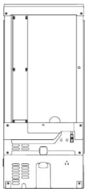
natural_image
Pure technical line drawing of a mechanical or electronic component without any text, numbers, or symbolsDrain pump model Gravity drain
The ideal installation has a standpipe with a 1½" (3.81 cm) to 2" (5.08 cm) PVC drain reducer installed directly below the outlet of the drain tube as shown. You must maintain a 1" (2.54 cm) air gap between the drain hose and the standpipe.
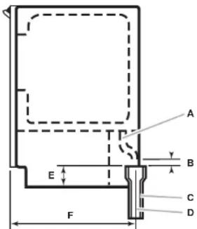
| Gravity Drain System Dimensions | ||
| Drain Hose A | ||
| Air Gap B 1" (2.54 cm) | ||
| PVC Drain Reducer C | 2" to 1 12 " (5 cm - 3.8 cm) | |
| Center of Drain D | 23" (58.4 cm) from front of door, with or without 3/4" (1.9 cm) panel on the door, centered left to right (7 516 " [18.56 cm]) from either side of the ice maker. | |
| Bottom of Ice Maker to top of PVC Drain Reducer | E 1 | 716 " (4.8 cm) |
| Depth to center of PVC Drain Reducer | F 23" (58.4 cm) | |
DRAIN PUMP SYSTEM
Drain pump maximum capability: For every 1 ft (0.31 m) of rise, subtract 10 ft (3.1 m) of maximum allowable run.
IMPORTANT: A drain pump is necessary when a floor drain is not available. A Drain Pump kit, Part Number 1901A, is available for purchase at jennair.com/accessories/details/1901A.
NOTE: It may be desirable to insulate the drain line thoroughly up to the drain inlet. An Insulation Sleeve kit, Part Number WI0365792, is available for purchase at
jennair.com/accessories/details/W10365792.
DOOR REVERSAL
REMOVING HINGE COVERS
natural_image
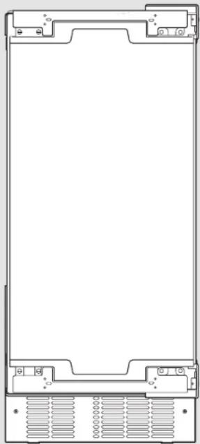
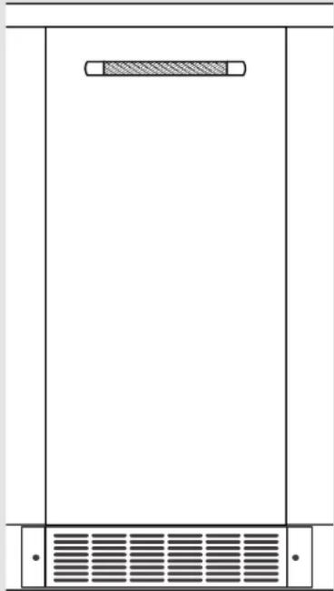
Front view of a rectangular electronic device with mounting brackets and ventilation slots (no text or symbols)12 | DOOR REVERSAL
! If door reversal is not needed, skip "Door Reversal" section.
WARNING

Electrical Shock Hazard
Disconnect power before servicing.
Replace all parts and panels before operating.
Failure to do so can result in death or electrical shock.
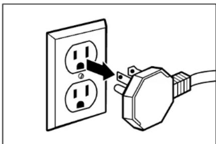
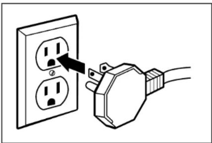
natural_image
Illustration of a plug inserted into two socket outlets, showing the power line (no text or symbols)1 Unplug the ice maker or disconnect power.
DOOR REVERSAL
WARNING

Crush Hazard
Articulated hinges are self closing and many pinch points exist prior to cabinet installation.
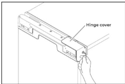
Do not remove hinge covers until product is ready to be installed.
Failure to follow these instructions can result in crush, cut, or pinch injuries.
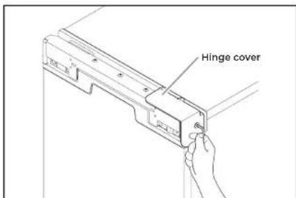
2 Remove the screws attaching top and bottom hinge covers using an 3/16" hex driver.
natural_image
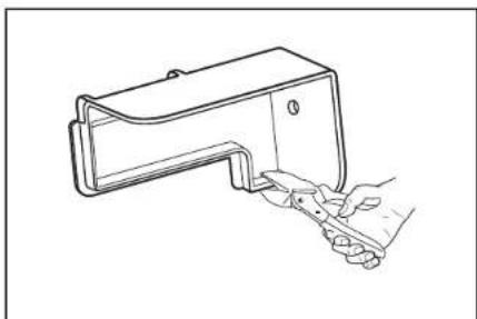
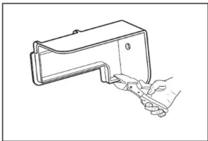
Line drawing of a hand holding a small object with a handle, no text or symbols present3 Using pliers, remove the hinge covers from the top and bottom hinges.
NOTE: Save the hinge covers for future use. Reinstall the hinge covers if product is removed from cabinet installation.
DOOR REVERSAL
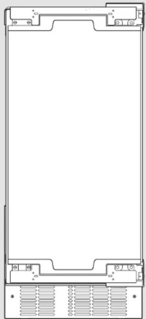
REMOVING THE HINGES
natural_image
Front view of a rectangular electronic device with mounting brackets and ventilation slots (no text or symbols)14 | DOOR REVERSAL
WARNING
Excessive Weight Hazard
Use two or more people to move and install ice maker.
Failure to do so can result in back or other injury.
natural_image
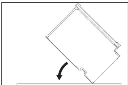
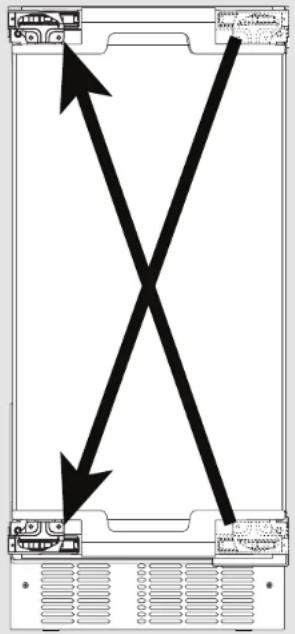
Simple line drawing of a tilted rectangular object with an arrow indicating rotational motion (no text or symbols)1
Lay down the ice maker as shown in the illustration. Be sure to cover the floor with cardboard or hardboard to avoid damaging it.
DOOR REVERSAL
natural_image
Technical line drawing of a mechanical assembly with mounting brackets and a directional arrow (no text or symbols)
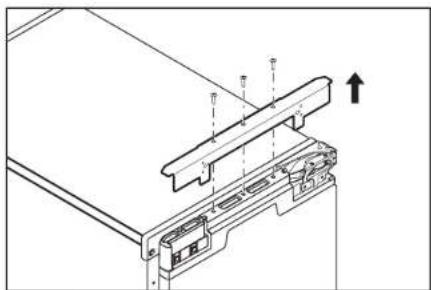
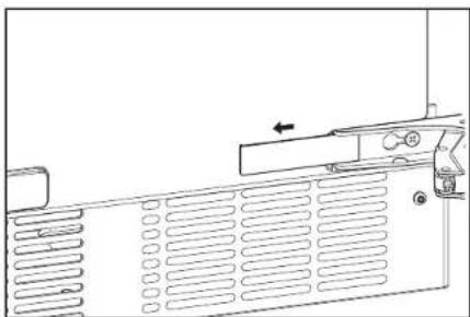
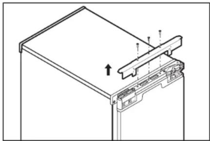
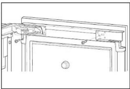
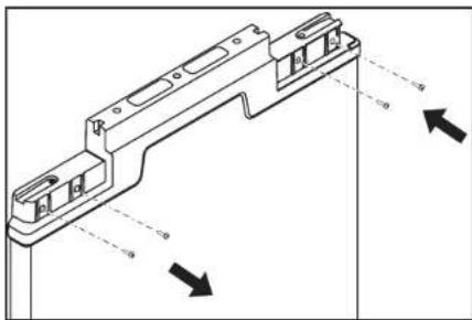
Remove the screws and the top metal bracket using the Phillips screwdriver. Place them aside.
natural_image
Technical line drawing of a computer monitor with an open lid and directional arrows indicating assembly or movement (no text or symbols)
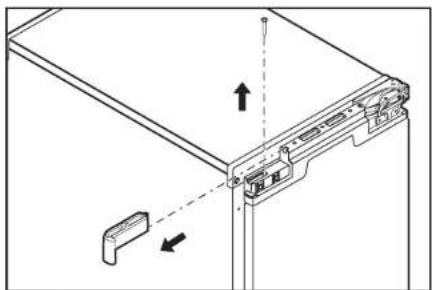
Remove the screw from the top and bottom end caps using the Phillips screwdriver. Remove and place them aside.
natural_image
Technical line drawing of a mechanical assembly with no visible text or symbols
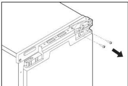
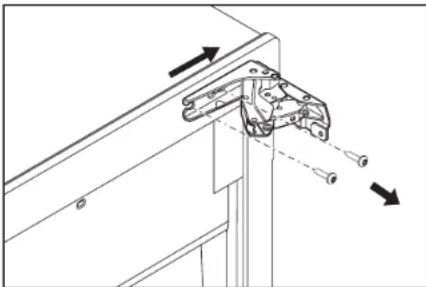
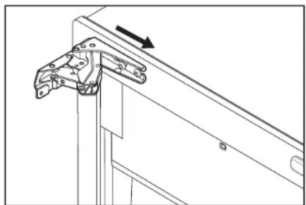
Using Torx T25 screwdriver unscrew the door hinge screws completely from the top and bottom hinges and place them aside.
DOOR REVERSAL
REMOVING THE HINGES (CONT.)
natural_image
Front view of a rectangular electronic device with mounting brackets and ventilation slots (no text or symbols)
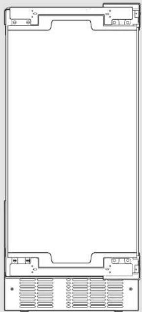
5 Remove the door and place it aside. Swap the hinge screws to the opposite side.
natural_image
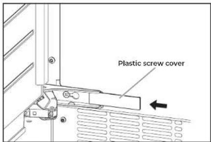
Technical line drawing of a computer ventilation panel with ventilation grilles and a door handle (no text or symbols)6 Remove the plastic screw cover from the inside of the hinges and place them aside.
DOOR REVERSAL
natural_image
Technical line drawing of a mechanical clamp or bracket assembly with directional arrows indicating movement (no text or symbols)7
Remove the screws and hinges from the cabinet with the Torx T25 screwdriver and place them aside.
natural_image
Diagram of a computer drive with an arrow indicating rotation (no text or symbols present)8
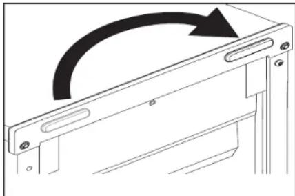
Remove the screw cap cover and replace on the other side.
natural_image
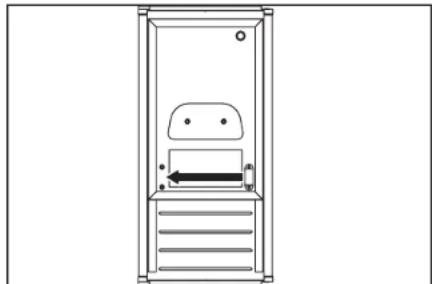
Line drawing of a vertical cabinet with internal compartments and a horizontal arrow indicating direction (no text or symbols)9
Swap the magnetic door catch to other side.
WARNING

Crush Hazard
Articulated hinges are self closing and many pinch points exist prior to cabinet installation.
Do not operate, or close, the hinges while they are removed from the ice maker.
Failure to follow these instructions can result in crush, cut, or pinch injuries.
DOOR REVERSAL
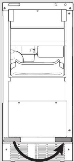
PREPARING THE BOTTOM HINGES
natural_image
Technical line drawing of a mechanical assembly with internal components and a curved arrow indicating motion (no text or symbols)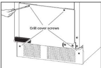
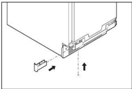
1 Unscrew and remove the grill cover using a TORX T20 screwdriver. Place them aside.
natural_image
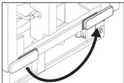
Technical line drawing of a mechanical assembly with a curved arrow indicating motion (no text or symbols)2 Remove the screw cover and place it on the other side as shown in the illustration.
DOOR REVERSAL
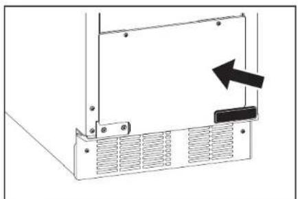
natural_image
Diagram of a computer monitor rear panel with ventilation grilles and a black arrow indicating the right side (no text or symbols present)3
Reinstall the grill cover.
DOOR REVERSAL
REVERSING THE HINGES
20 | DOOR REVERSAL

natural_image
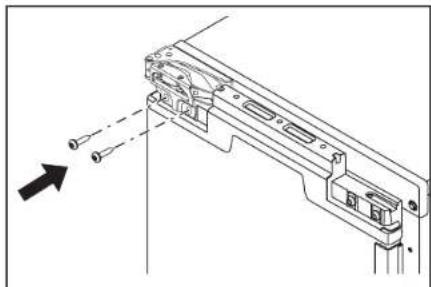
Technical line drawing of a mechanical bracket with mounting holes and dashed alignment lines (no text or symbols)1 Install the hinge screws (placed aside in step 7 of "Preparing the Bottom Hinges") half way on the desired side of the cabinet.
natural_image
Technical line drawing of a mechanical bracket assembly with an arrow indicating direction (no text or symbols)3 Take the original bottom hinge, flip it and place it in the top hinge position on the opposite side. Slide onto the cabinet hinge screws.
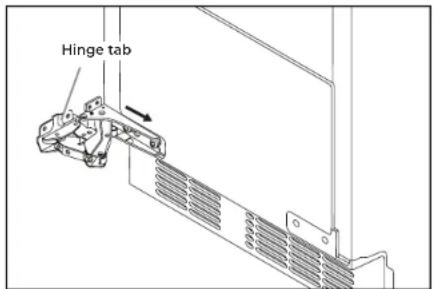
2 Take the original top hinge, flip it and place it in the bottom hinge position on the opposite side. Slide onto the cabinet hinge screws. The hinge tabs on the hinges should always face towards each other.
4 Fully tighten the top and bottom hinge screws.
DOOR REVERSAL
5
Reinstall the plastic screw cover to original locations on the hinges.
natural_image
Technical diagram of a mechanical assembly with arrows indicating direction (no text or symbols)7
Reinstall the top and bottom end caps on the door (the top right end cap is now the bottom left end cap and vice versa).
NOTE: For custom wood install skip this step.
WARNING
Excessive Weight Hazard
Use two or more people to move and install ice maker.
Failure to do so can result in back or other injury.
natural_image
Technical line drawing of a mechanical assembly with no visible text or symbols6
Slide the door onto the hinges. Using Torx T25 screwdriver install the screws (removed in the step 6 of "Removing the Hinges" section) onto the door.
natural_image
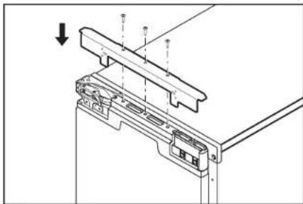
Technical line drawing of a mechanical assembly with mounting brackets and a downward arrow indicator (no text or symbols)8
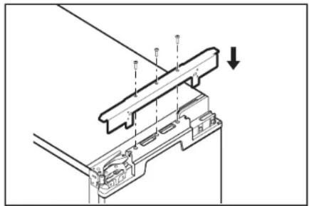
Reinstall the top metal bracket on the door.
NOTE: For stainless steel panel install skip this step.
natural_image
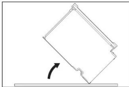
Simple line drawing of a tilted rectangular object with an arrow indicating rotational motion (no text or symbols)9
Return the ice maker back to upright position.
INSTALLATION
natural_image
Technical line drawing of a mechanical device with mounting holes and internal components (no text or symbols)22 | INSTALLATION
! If ice maker is not connected to the water supply, skip this section and go to "Installing the Drain Pump and Drain Hose" section.
NOTES:
■Connect drain pump to your drain in accordance with all state and local codes and ordinances.
■It may be desirable to insulate drain tube thoroughly up to drain inlet to minimize condensation on the drain tube. Insulated tube kit Part Number W10365792 is available for purchase.
■Drain pump is designed to pump water to a maximum height of 10 ft (3 m). Use only Whirlpool approved drain pump kit Part Number 1901A.
■Do not connect the outlet end of the drain tube to a closed pipe system to avoid drain water from backing up into the ice maker.
Kit Contains:
■Drain pump kit Part Number 1901A
■5/8" I.D. x 51/8" drain tube (ice maker bin to drain pump reservoir inlet)
■1/2" I.D. x 10 ft (3 m) drain tube hose (drain pump discharge to household drain)
■5/16" I.D. x 32" (81 cm) vent tube (drain pump reservoir vent to ice maker cabinet back)
■Cable tie (secures vent tube to suction tube) (1)
■#8-32 x 3/8" pump mounting screws (secures drain pump to baseplate and clamps to back of ice maker) (5)
■5/8" small adjustable hose clamp (secures vent to drain pump)
■7/8" large adjustable hose clamp, (secures drain tube to ice maker bin and drain pump reservoir inlet) (3)
■Instruction sheet
If Ice Maker is Currently Installed
WARNING

Electrical Shock Hazard
Disconnect power before servicing.
Replace all parts and panels before operating.
Failure to do so can result in death or electrical shock.

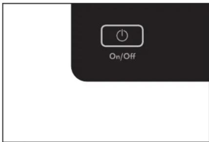
Press the OFF button to Stop ice production. Then unplug the ice maker or disconnect power.
INSTALLATION
natural_image
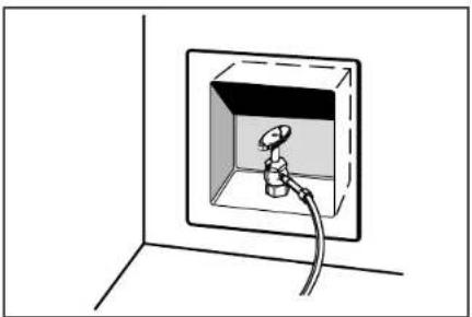
Simple line drawing of a wall-mounted electrical outlet with a bulb and cable (no text or symbols)2 Turn off water supply. Wait 5 to 10 minutes for the ice to fall into the storage bin. Remove all ice from bin.
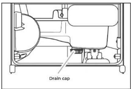
4 Unscrew the drain cap from the bottom of the water pan located inside the storage bin. Allow water to drain completely.
natural_image
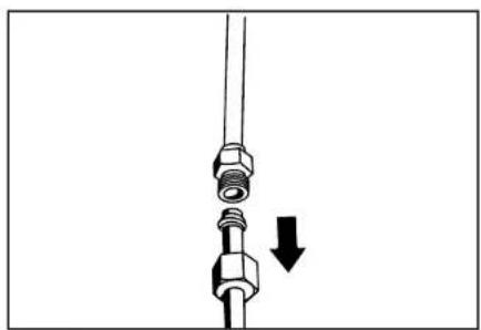
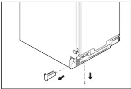
Diagram of a mechanical assembly with bolts and a downward arrow indicating motion (no text or symbols)5 Disconnect water supply line.
natural_image
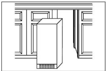
Pure architectural line drawing of a building facade with a central tower and window (no text or symbols)3 If ice maker is built into cabinets, pull ice maker out of the opening.
INSTALLATION
INSTALLING THE DRAIN PUMP AND DRAIN HOSE
natural_image
Technical line drawing of a mechanical or electronic component with mounting holes and internal components (no text or symbols)NOTE: Do not kink, smash or damage tubes or wires during installation.
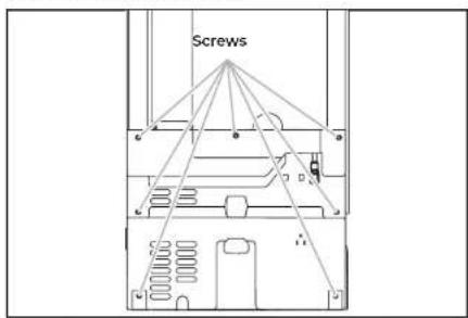
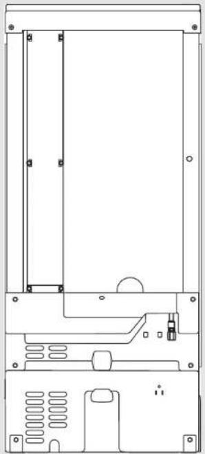
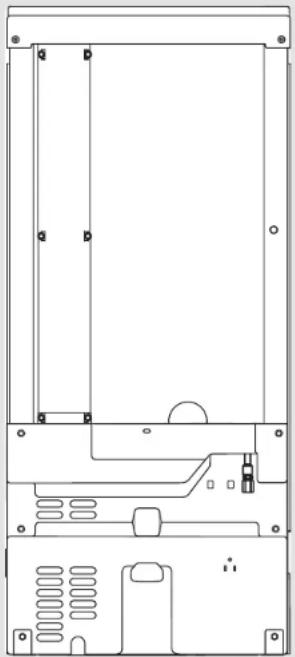
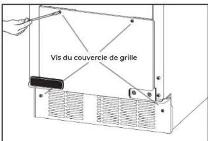
1 Unscrew the screws attaching rear panel to ice maker. Remove the screws and rear panel, place them aside. For pump models, skip to step 12.
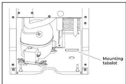
3 Install the drain pump on the right side of the ice maker base. Tip the drain pump slightly to slide the mounting tab into the mounting tab slot.
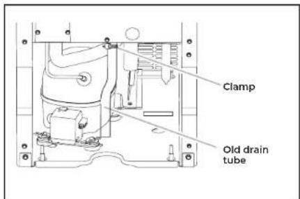
2 Remove the old drain tube and clamp attached to the ice maker bin. NOTE: Discard old drain tube and clamp.
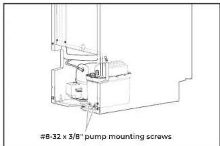
4 Align the two screw holes at the rear of the pump. Use the two #8-32 x 3/8" screws supplied to attach the pump to the ice maker base.
INSTALLATION
5
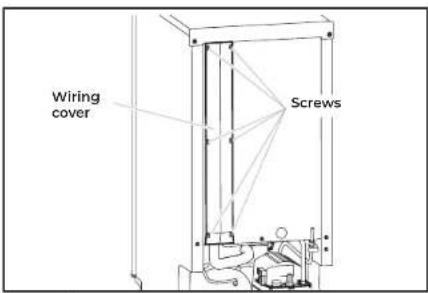
Unscrew the screws attaching wiring cover to the ice maker and remove the wiring cover. Place the screws and wiring cover aside.
6
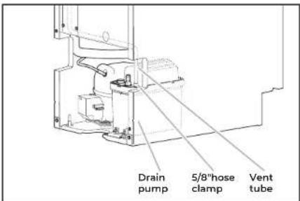
Install vent tube [5/16" I.D. x 32" (81 cm)] to drain pump reservoir vent. Use one of the supplied 5/8" small adjustable clamp.
NOTE:
■Do not block air flow through the vent tube by over tightening the cable tie.
7
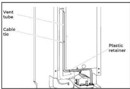
Route the vent tube through the plastic retainer as shown in the illustration. Using a cable tie, tie the vent tube to the suction tube and wires located behind the wiring cover. Reinstall the wiring cover and screws.
NOTE:
■Do not overtighten the vent tube, it may block the airflow through tube.
8
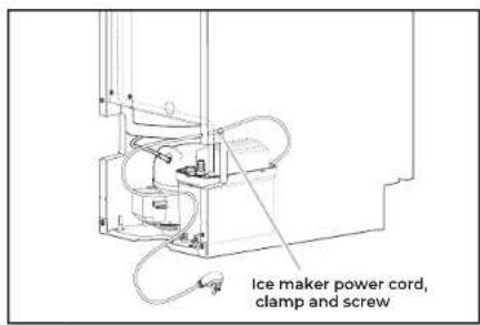
Unscrew and remove the power cord clamp mounted to the ice maker side wall from the ice maker power cord.
INSTALLATION
INSTALLING THE DRAIN PUMP AND DRAIN HOSE (CONT.)
natural_image
Technical line drawing of a mechanical or electronic component with no visible text, numbers, or symbols.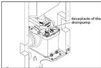
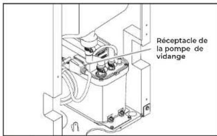
9 Coil the ice maker power cord into a 4" (10.2 cm) diameter coil. Restrain the coil with electrical tape or cable ties. Place the coiled power cord as shown in the illustration and plug it into the receptacle on the drain pump.
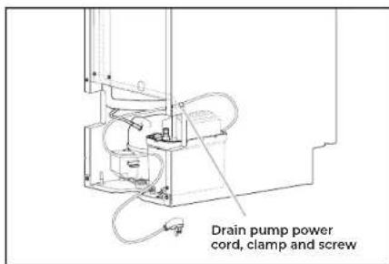
10 Attach the drain pump power cord to the ice maker side wall with the clamp and screw (removed in step 7).
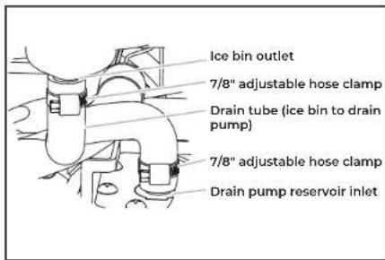
11 New drain tube is provided in the drain pump kit. Install new drain tube to both the ice bin outlet and the drain pump reservoir inlet using new adjustable clamps.
NOTES:
- Do not kink.
- Trim tube length if required.
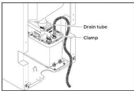
12 Attach the drain tube to pump discharge tube using a clamp provided.
INSTALLATION
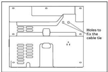

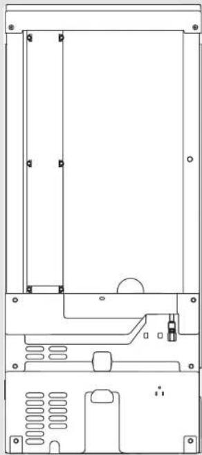
Install the cable tie on the rear panel using two holes provided on the rear panel.
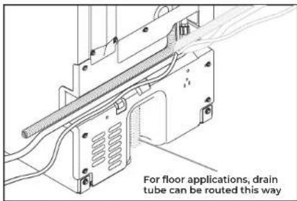

Route the drain pump discharge tube, power cord, and water inlet through the slot in the ice maker back panel. Replace the rear panel and screws.
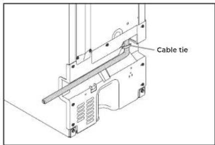

Using a cable tie, fix the drain tube to rear panel as shown in the illustration.
INSTALLATION
CONNECTING THE WATER SUPPLY
natural_image
Technical line drawing of a mechanical device casing with mounting holes and internal components (no text or symbols)28 | INSTALLATION
IMPORTANT:
■Plumbing shall be installed in accordance with the International Plumbing Code and any local codes and ordinances.
■Use copper tubing or JennAir supply line, Part Number 8212547RP, and check for leaks.
■Install tubing only in areas where temperatures will remain above freezing.
Turn off main water supply. Turn on nearest faucet line long enough to clear line of water.
natural_image
Simple line drawing of a wall-mounted electrical outlet with a plug inserted (no text or symbols)1 Using a minimum 1/2" copper tubing with a quarter turn shut-off valve or the equivalent supply line, connect the ice maker as shown.
natural_image
Line drawing of a mechanical connector or fitting with a curved cable (no text or symbols)
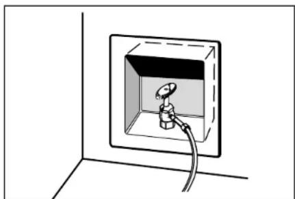
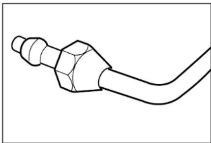
Use 1/4" (6.35 mm) O.D. soft copper tubing or Whirlpool approved refrigerator water hose with square cut ends for the cold water supply. Slip the compression sleeve and nut onto the copper tubing. Be sure that you have the proper length needed for the job.

Route the water line through the cabinetry to the ice maker utility cutout. Be sure there water line extends 30" beyond the cabinet for future servicing purpose.
INSTALLATION
natural_image
Line drawing of a bucket with a hand holding a tool above it, no text or symbols present
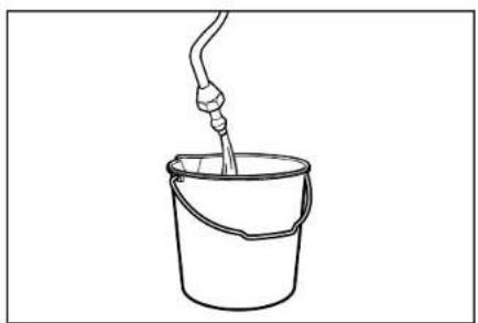
Flush out tubing by placing the free end of the tubing into a container or sink, and turning on the main water supply until water is clear. Turn off shut-off valve on the water pipe.
IMPORTANT: Always drain the water line before making the final connection to the inlet of the water valve to avoid possible water valve malfunction.
natural_image
Diagram of a mechanical component with a downward arrow indicating force or direction (no text or symbols)
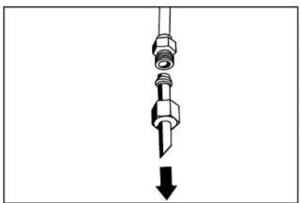
Remove and discard the short, plastic tube from the end of the water line inlet.
natural_image
Technical line drawing of a computer chassis showing internal components and a cable (no text or symbols)
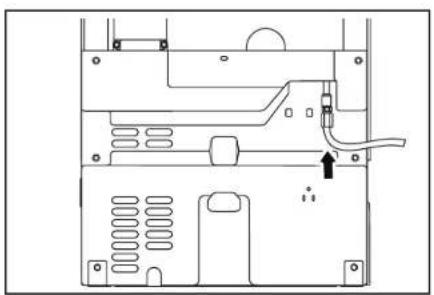
Insert end of tubing squarely into outlet end as far as it will go. Screw compression nut onto outlet end with adjustable wrench. Tighten the nut by hand. Then tighten it with a wrench two more turns. Do not overtighten.
natural_image
Simple line drawing of a wall-mounted electrical socket with a cable, no text or symbols present
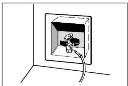
Turn shutoff valve on. Check for leaks. Tighten any connections (including connections at the valve) or nuts that leak.
INSTALLATION
LEVELING AND SECURING

natural_image
Simple line drawing of a rectangular enclosure or storage unit with a central slotted lid and ventilation grilles (no text or symbols)WARNING
Excessive Weight Hazard
Use two or more people to move and install ice maker.
Failure to do so can result in back or other injury.
natural_image
Diagram of a server unit with an arrow indicating direction, enclosed in a window frame (no text or symbols)
Move the ice maker in front of its final location. Be sure to cover the floor with cardboard or hardboard to avoid damaging it.
INSTALLATION
WARNING

Crush Hazard
Articulated hinges are self closing and many pinch points exist prior to cabinet installation.
Do not remove hinge covers until product is ready to be installed.
Failure to follow these instructions can result in crush, cut, or pinch injuries.
2 Remove the screws attaching top and bottom hinge covers using an 3/16" hex driver.
natural_image
Line drawing of a hand holding a small electronic device with a handle (no text or symbols)3 Using pliers, remove the hinge covers from the top and bottom hinges.
NOTE: Save the hinge covers for future use. Reinstall the hinge covers if product is removed from cabinet installation.
INSTALLATION
LEVELING AND SECURING (CONT.)

natural_image
Simple line drawing of a rectangular enclosure with a horizontal bar and ventilation grille (no text or symbols)32 | INSTALLATION
4 Install the door panel according to the instructions in the "Custom Wood Door Panel" section or instructions received with the stainless steel panel received with kit.
natural_image
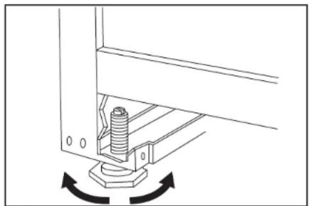
Mechanical assembly diagram showing a bolt inserted into a bracket with rotational arrows indicating motion (no text or symbols)5
Use ice maker leveling legs to align ice maker door to the adjacent cabinet opening.
WARNING
Excessive Weight Hazard
Use two or more people to move and install ice maker.
Failure to do so can result in back or other injury.
INSTALLATION
natural_image
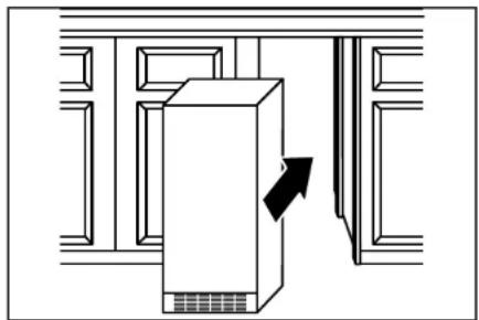
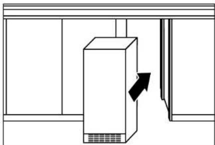
Simple line drawing of a cabinet with an arrow indicating direction, no text or symbols present6
Slide ice maker into the cabinet while managing the utility connection positions behind the ice maker. Be sure to cover the floor with cardboard or hardboard to avoid damaging it. IMPORTANT: For the flush install, the ice maker utility connections must be routed out through the slot in the ice maker rear panel.
natural_image
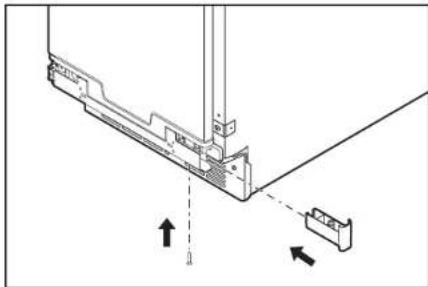
Pure technical line drawing of a mechanical component with no text, numbers, or symbols7
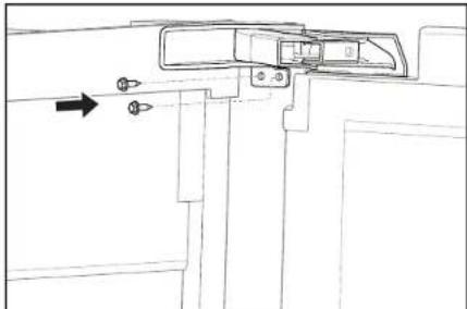
Be sure that the ice maker is at desired depth. Secure the top and bottom hinges to the side of the cabinet using wood screws.
8
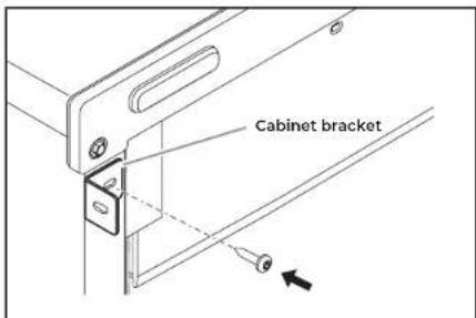
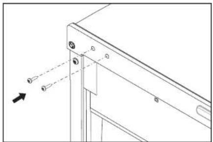
Attach the cabinet brackets (provided with ice maker) to the holes in the front of ice maker as shown in the illustration. Attach the cabinet brackets to the side of the cabinet with wood screws.
NOTE: For the custom wood panel installation, continue installation at step 6 of "Custom wood panel installation."
INSTALLATION
CUSTOM WOOD DOOR PANEL
natural_image
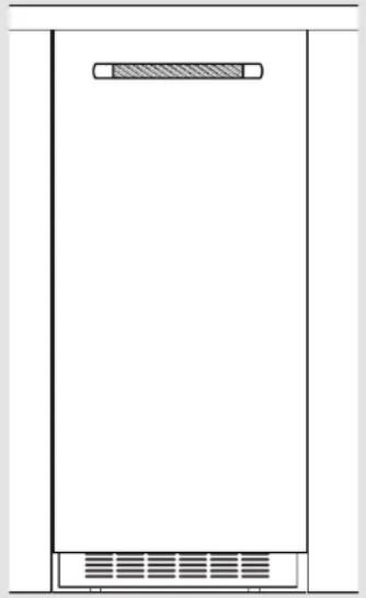
Simple line drawing of a rectangular container with a side panel and ventilation grille (no text or symbols)34 | INSTALLATION
If stainless steel panel is installed, skip "Custom Wood Door Panel" section.!
natural_image
Technical line drawing of a mechanical assembly with mounting brackets and a central component (no text or symbols)1 Remove screws and the top metal bracket using the Phillips screwdriver. Remove and place them aside. Skip this step and go to the step 4 if the door reversal has been completed.
natural_image
Technical diagram of a mechanical assembly with no visible text or symbols3 Reinstall top metal bracket using screws removed in the step 1.
natural_image
Technical diagram showing a mechanical assembly with arrows indicating direction (no text or symbols present)2 Remove the top and bottom end caps using the Phillips screwdriver and place them aside.
natural_image
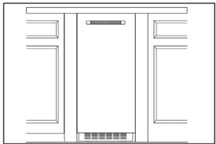
Pure architectural line drawing of a double door with no text, numbers, or symbols4 Lightly press the custom panel onto the door using double sided adhesive tape. Adjust height of the panel to align with the adjacent cabinetry. Press the panel firmly against door.
INSTALLATION
natural_image
Technical line drawing of a mechanical assembly with no visible text or symbols5
From inside the door, install the wood screws through the slotted holes in the metal brackets.
Continue to "Leveling and Securing" section at step 5.
natural_image
Line drawing of a double door with front panel and side panels (no text or symbols)6
Adjust the panel side to side to achieve a desired gap on both sides. Install the remaining screws through the door bracket into the panel.
NOTE: Be sure that the panel is aligned with adjacent cabinet before installing the remaining screws to secure the door panel.
natural_image
Technical diagram showing a mechanical assembly with directional arrows indicating movement or force (no text or symbols present)7
Replace the top and bottom end caps into the door. Fix the bottom end cap using screw through the bottom metal bracket hole.
INSTALLATION
CONNECTING THE DRAIN

natural_image
Simple line drawing of a rectangular container with a side panel and ventilation grille (no text or symbols)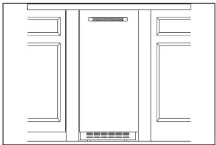
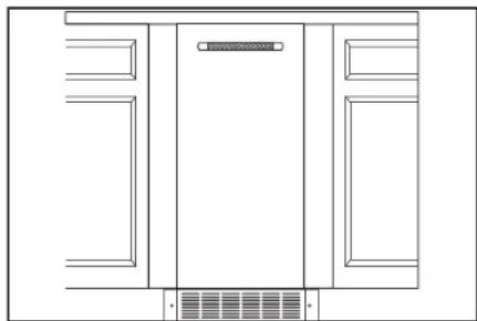
natural_image
Pure architectural line drawing of a symmetrical room layout with no text, numbers, or symbols
Style 1-For a gravity drain system, be sure that the ice maker drain tube is positioned over the PVC drain reducer. See the "Gravity Drain System" section.
Style 2-For a drain pump system, connect the drain pump outlet hose to the drain. Refer the "Drain Supply Requirements" section.
NOTE: Do not connect outlet end of drain tube to a closed pipe system to avoid drain water from backing up into the ice maker.
WARNING

Electrical Shock Hazard
Plug into a grounded 3 prong outlet.
Do not remove ground prong.
Do not use an adapter.
Do not use an extension cord.
Failure to follow these instructions can result in death, fire, or electrical shock.
INSTALLATION
natural_image
Diagram showing a plug inserted into two outlets of an electrical socket, with no text or symbols present.
Plug in ice maker or reconnect power.

Turn on ice maker. Wait for rinsing cycle, approximately 5 minutes, to be sure the ice maker is operating properly.
INSTALLATION
INSTALLING AUXILIARY GRILL
natural_image
Pure technical diagram of a rectangular enclosure or enclosure with no text, numbers, or symbols38 | INSTALLATION
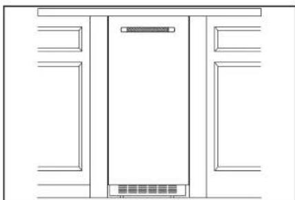
The auxiliary grill is an optional accessory. It can be used to align the toe grill with the rest of the cabinets (while not obstructing ventilation of the ice maker).
NOTE: Install auxiliary grill only after finishing the complete ice maker installation.
1 Remove packaging material and discard it.
2 Remove the screws that are taped inside the auxiliary grill.
3 Place grill onto cabinetry. Align part so that grating pattern on the auxiliary grill matches that of the toe grill on the ice maker.
4 Center auxiliary grill on cut out for ice maker. Mark hole locations on each side of auxiliary grill on cabinet.
5 Using power drill and a 1/8" drill bit, drill holes in cabinet. This is to fit screws of size #8-18 x 0.750".
natural_image
Pure architectural line drawing of a cabinet or enclosure structure without any text, numbers, or symbols6 Using the TORX T20 screwdriver, screw auxiliary grill into cabinet.
INSTALLATION
APPENDIX
ACCESSORIES
IMPORTANT: A drain pump is necessary when a floor drain is not available. A Drain Pump kit, Part Number 1901A, is available for purchase at https://www.jennalr.com/
NOTE: It may be desirable to insulate the drain line thoroughly up to the drain inlet. An Insulation Sleeve kit, Part Number W10365792, is available for purchase at https://www.jennair.com/
To order a Stainless Steel Door Panel kit, visit https://www.jennair.com/
To order JennAir Handle kit for custom wood door panel, visit https://www.jennair.com/
To order Copper Refrigerator Water Supply kit (8003RP), visit https://www.jennalr.com/
To order Industrial Grade Refrigerator Water Hose (WI0505928RP), visit https://www.jennair.com/
APPENDIX

natural_image
Abstract geometric design with a white number '4' and 'TM' on a dark, glossy surface (no readable text or symbols)INTRODUCTION
SÉCURITÉ
natural_image
Pure technical line drawing of a mechanical or electrical component without any text, numbers, or symbolsnatural_image
Technical line drawing of a mechanical or electronic component with no visible text, numbers, or symbols.natural_image
Front view of a rectangular electronic device with mounting brackets and ventilation slots (no text or symbols)AVERTISSEMENT

natural_image
Diagram showing a plug inserted into two socket outlets, with an arrow indicating the insertion point (no text or symbols present)natural_image
Line drawing of a hand holding a tool interacting with a mechanical component (no text or symbols)natural_image
Front view of a rectangular electronic device with mounting brackets and ventilation grilles (no text or symbols)54 | INVERSION DE LA PORTE
AVERTISSEMENT
natural_image
Simple line drawing of a tilted rectangular object with an arrow indicating downward motion (no text or symbols)1
natural_image
Technical line drawing of a mechanical assembly with mounting brackets and a directional arrow (no text or symbols)natural_image
Technical line drawing of a computer monitor with an open lid and internal components (no text or symbols)natural_image
Technical line drawing of a mechanical component with mounting holes and a dashed arrow indicating direction (no text or symbols)natural_image
Pure technical line drawing of a rectangular electronic component with mounting brackets and ventilation slots (no text or symbols)56 | INVERSION DE LA PORTE
natural_image
Line drawing of a computer ventilation grille with a right-angle indicator (no text or symbols)natural_image
Technical line drawing of a mechanical clamp or bracket assembly with directional arrows indicating movement (no text or symbols)natural_image
Diagram of a computer drive with an arrow indicating rotation (no text or symbols present)natural_image
Line drawing of a vertical cabinet with internal compartments and a horizontal arrow indicating direction (no text or symbols)natural_image
Technical line drawing of a mechanical device interior with no visible text or symbols58 | INVERSION DE LA PORTE
natural_image
Technical line drawing of a mechanical assembly with a curved arrow indicating motion (no text or symbols)natural_image
Diagram of a computer monitor rear panel with ventilation grilles and a black arrow indicating the right side (no text or symbols present)3
natural_image
Diagram of a device rear panel with two opposing arrows indicating bidirectional movement (no text or symbols)60 | INVERSION DE LA PORTE
natural_image
Technical line drawing of a mechanical bracket with mounting holes and dashed alignment lines (no text or symbols)natural_image
Technical line drawing of a mechanical bracket assembly with an arrow indicating direction (no text or symbols)natural_image
Technical diagram of a mechanical assembly with arrows indicating direction (no text or symbols)natural_image
Technical line drawing of a mechanical bracket assembly with no visible text or symbolsnatural_image
Technical line drawing of a mechanical assembly with mounting brackets and a downward arrow indicator (no text or symbols)natural_image
Simple line drawing of a tilted rectangular object with an arrow indicating rotational motion (no text or symbols)natural_image
Technical line drawing of a computer chassis frame with mounting holes and internal components (no text or symbols)62 | INSTALLATION
natural_image
Simple line drawing of a wall-mounted electrical outlet with a bulb and cable (no text or symbols)natural_image
Diagram of a mechanical assembly with bolts and a downward arrow indicating motion (no text or symbols)natural_image
Pure architectural line drawing of a building facade with a central tower and window (no text or symbols)natural_image
Technical line drawing of a computer chassis frame with mounting holes and internal components (no text or symbols)64 | INSTALLATION
natural_image
Technical line drawing of a mechanical or electronic component with mounting holes and internal components (no text or symbols)66 | INSTALLATION
natural_image
Technical line drawing of a mechanical device casing with mounting holes and internal components (no text or symbols)68 | INSTALLATION
IMPORTANT :
natural_image
Simple line drawing of a wall-mounted electrical outlet with a plug inserted (no text or symbols)natural_image
Line drawing of a mechanical connector or pipe fitting (no text or symbols)
natural_image
Line drawing of a bucket with a hand holding a tool above it, no text or symbols present
natural_image
Diagram of a mechanical component with a downward arrow indicating force or direction (no text or symbols)
natural_image
Technical line drawing of a computer motherboard showing internal components and a highlighted connection point (no text or symbols)
natural_image
Simple line drawing of a wall-mounted electrical outlet with a cable inserted, no text or symbols present.
natural_image
Simple line drawing of a rectangular device with a horizontal bar and ventilation grille (no text or symbols)70 | INSTALLATION
AVERTISSEMENT
natural_image
Diagram of a refrigerator with an arrow indicating direction, no text or symbols present
natural_image
Line drawing of a hand holding a small electronic device (no text or symbols)natural_image
Simple line drawing of a rectangular device with a horizontal bar and ventilation grille (no text or symbols)72 | INSTALLATION
natural_image
Technical diagram of a mechanical assembly with a bolt and hexagonal base, showing rotational motion arrows (no text or symbols)natural_image
Simple line drawing of a cabinet with an arrow indicating direction, no text or symbols present6
natural_image
Technical line drawing of a mechanical component with arrows indicating direction (no text or symbols)7
8
natural_image
Simple line drawing of a rectangular device with a horizontal bar and ventilation grille (no text or symbols)74 | INSTALLATION
natural_image
Technical line drawing of a mechanical assembly with mounting brackets and a central component (no text or symbols)natural_image
Technical line drawing of a mechanical assembly with no visible text or symbolsnatural_image
Technical diagram showing a mechanical assembly with arrows indicating direction (no text or symbols present)natural_image
Pure architectural line drawing of a double door with no text, numbers, or symbolsnatural_image
Technical line drawing of a mechanical assembly with no visible text or symbols5
natural_image
Line drawing of a double door with front panel and side panels (no text or symbols)6
natural_image
Technical diagram showing a mechanical assembly with directional arrows indicating movement or force (no text or symbols present)7
natural_image
Simple line drawing of a rectangular device with a horizontal bar and ventilation grille (no text or symbols)76 | INSTALLATION
natural_image
Pure architectural line drawing of a cabinet or enclosure structure without any text, numbers, or symbols
natural_image
Diagram showing a plug inserted into two outlets of an electrical socket (no text or symbols present)natural_image
Pure technical diagram of a rectangular enclosure or enclosure with no text, numbers, or symbols78 | INSTALLATION
natural_image
Pure architectural line drawing of a room layout with no text, numbers, or symbols
- INTRODUCTION
- Your safety and the safety of others are very important.
- DANGER
- WARNING
- IMPORTANT SAFETY INSTRUCTIONS
- SAVE THESE INSTRUCTIONS
- REGISTERING YOUR APPLIANCE
- ■Streamline your warranty service
- ■Protect your purchase
- ■Keep your family safe
- PRODUCT IDENTIFICATION
- TABLE OF CONTENTS
- GETTING STARTED
- SITE PREPARATION
- DOOR REVERSAL
- INSTALLATION
- APPENDIX
- BEFORE INSTALLATION
- TOOLS REQUIRED
- PARTS PROVIDED
- VACATION OR EXTENDED TIME WITHOUT USE
- Excessive Weight Hazard
- REMOVING PACKAGING MATERIALS
- CLEANING BEFORE USE
- OPTIONAL PERSONALIZATIONS
- REVERSING THE DOOR
- CUSTOM PANEL INSTALLATION
- IMPORTANT:
- PARTS NEEDED:
- STAINLESS STEEL PANEL INSTALLATION
- PRODUCT AND
- OPENING DIMENSIONS
- LOCATION REQUIREMENTS
- TEMPERATURE
- LOCATION
- ELECTRICAL REQUIREMENTS
- Electrical Shock Hazard
- WATER SUPPLY REQUIREMENTS
- REVERSE OSMOSIS WATER SUPPLY
- DRAIN SUPPLY REQUIREMENTS
- DRAIN PUMP SYSTEM
- Crush Hazard
- NOTES:
- NOTE:
- CONNECTING THE WATER SUPPLY
- 6
- 7
- 8
- ACCESSORIES
- SÉCURITÉ
- AVERTISSEMENT
- 1
- IMPORTANT :
Brand : JENN-AIR
Model : JKRPR151HM
Category : Refrigerator