
W10748976 - Range hood JENN-AIR - Free user manual and instructions
Find the device manual for free W10748976 JENN-AIR in PDF.
| Product type | Gas range with recirculation ventilation system |
| Brand | JENN-AIR |
| Model | W10748976 |
| Dimensions (W x H x D) | 76.2 cm (30 in) width; height adjustable from 91.4 to 93.9 cm; depth 73.3 cm (28 7/8 in) |
| Power supply | Natural gas or propane (convertible); single-phase electric 240 V, 60 Hz, 40-50 A |
| Default gas type | Natural gas |
| Burner heat output | Up to 19,000 BTU (depending on burner) |
| Number of burners | 5 (including one dual burner on some models) |
| Oven | Oven with AquaLift® self-cleaning and electronic ignition system |
| Ventilation system | Recirculation fan with air filter |
| Air filter lifespan | 6 months with average use |
| Anti-tip bracket | Included and mandatory for safety |
| Certifications | UL, CSA International, compliant with US and Canadian standards |
| Weight | Not specified in the manual |
| Material | Stainless steel (finish available) |
| Warranty | See Use and Care Guide |
Frequently Asked Questions - W10748976 JENN-AIR
User questions about W10748976 JENN-AIR
0 question about this device. Answer the ones you know or ask your own.
Ask a new question about this device
Download the instructions for your Range hood in PDF format for free! Find your manual W10748976 - JENN-AIR and take your electronic device back in hand. On this page are published all the documents necessary for the use of your device. W10748976 by JENN-AIR.
USER MANUAL W10748976 JENN-AIR
DUCTLESS INSTALLATION INSTRUCTIONS SLIDE-IN DOWNDRAFT RANGES
INSTRUCTIONS D'INSTALLATION SANS CONDUIT DES CUISINIÈRES À ÉVACUATION PAR LE BAS ENCASTRABLES
Table of Contents/Table des matières
RANGE SAFETY....2
INSTALLATION REQUIREMENTS ....4
Tools and Parts 4
Location Requirements 5
Electrical Requirements – U.S.A. Only 7
Electrical Requirements – Canada Only 8
Gas Supply Requirements 8
INSTALLATION INSTRUCTIONS 9
Unpack Range 9
Adjust Leveling Legs 10
Install Anti-Tip Bracket 10
Install Recirculation Blower Assembly 11
Install Blower 13
Make Service Connections 14
Complete Filter Assembly 16
Verify Anti-Tip Bracket Is Installed and Engaged 17
Oven Door 17
Complete Installation.... 18
Electronic Ignition System 19
GAS CONVERSIONS 19
LP Gas Conversion 19
Natural Gas Conversion.... 21
Adjust Flame Height.... 23
REPLACING AIR FILTER 24
SÉCURITÉ DE LA CUISINIÈRE 25
EXIGENCES D'INSTALLATION 26
Your safety and the safety of others are very important.
We have provided many important safety messages in this manual and on your appliance. Always read and obey all safety messages.

This is the safety alert symbol.
This symbol alerts you to potential hazards that can kill or hurt you and others.
All safety messages will follow the safety alert symbol and either the word "DANGER" or "WARNING."
These words mean:
DANGER
You can be killed or seriously injured if you don't immediately follow instructions.
WARNING
You can be killed or seriously injured if you don't follow instructions.
All safety messages will tell you what the potential hazard is, tell you how to reduce the chance of injury, and tell you what can happen if the instructions are not followed.
WARNING: For your safety, the information in this manual must be followed to minimize the risk of fire or explosion, or to prevent property damage, personal injury, or death.
- Do not store or use gasoline or other flammable vapors and liquids in the vicinity of this or any other appliance.
-
WHAT TO DO IF YOU SMELL GAS:
-
Do not try to light any appliance.
- Do not touch any electrical switch; do not use any phone in your building.
- Clear the room, building, or area of all occupants.
- Immediately call your gas supplier from a neighbor's phone. Follow the gas supplier's instructions.
- If you cannot reach your gas supplier, call the fire department.
- Installation and service must be performed by a qualified installer, service agency, or the gas supplier.
WARNING: Gas leaks cannot always be detected by smell.
Gas suppliers recommend that you use a gas detector approved by UL or CSA.
For more information, contact your gas supplier.
If a gas leak is detected, follow the "What to do if you smell gas" instructions.
IMPORTANT: Do not install a ventilation system that blows air downward toward this gas cooking appliance. This type of ventilation system may cause ignition and combustion problems with this gas cooking appliance resulting in personal injury or unintended operation.
In the State of Massachusetts, the following installation instructions apply:
■ Installations and repairs must be performed by a qualified or licensed contractor, plumber, or gasfitter qualified or licensed by the State of Massachusetts.
■ If using a ball valve, it shall be a T-handle type.
■ A flexible gas connector, when used, must not exceed 3 feet.
 | ⚠ WARNING |
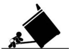
| Tip Over HazardA child or adult can tip the range and be killed.Install anti-tip bracket to floor or wall per installation instructions.Slide range back so rear range foot is engaged in the slot of the anti-tip bracket.Re-engage anti-tip bracket if range is moved.Do not operate range without anti-tip bracket installed and engaged.Failure to follow these instructions can result in death or serious burns to children and adults. | |
 Range Foot Range Foot | To verify the anti-tip bracket is installed and engaged:•Slide range forward.•Look for the anti-tip bracket securely attached to floor or wall.•Slide range back so rear range foot is under anti-tip bracket.•See installation instructions for details. |
INSTALLATION REQUIREMENTS
Tools and Parts
Gather the required tools and parts before starting installation. Read and follow the instructions provided with any tools listed here.
Tools Needed
■ Tape measure
Phillips screwdriver
■Flat-blade screwdriver
■1/8" (3 mm) flat-blade screwdriver
Level
Drill
■ Adjustable wrench
Slip joint pliers
■ Pipe wrench
■ ^15/16 " (2.4 cm) combination wrench
■ ^1/8 " (3.2 mm) drill bit (for wood floors)
■ Marker or pencil
■ Flashlight
■ Masking tape
■ Pipe-joint compound resistant to natural and LP gases
■ ^3/16 " (4.8 mm) carbide-tipped masonry drill bit (for concrete/ceramic floors)
■Noncorrosiveleak-detection solution
■ Sheet metal aluminum tape
■ 12 " (13 mm) combination wrench
■ 14 " (6 mm) nut driver
■ ^9/_32 " (7 mm) nut driver
For LP/Natural Gas Conversions
natural_image
Technical line drawing of a mechanical enclosure front (no text or symbols on the diagram itself)■ Front Lower Access Panel
natural_image
Isometric line drawing of a mechanical lever or bracket (no text or symbols)NOTE: This manual covers several models. Your product may vary from this image.
Hardware Bag
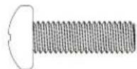
■ (5) M5 X 15 mm Screws
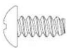
(3) #8 - 3/8" Screws
NOTE: Exhaust adapter from the blower mounting kit and lower access panel that shipped with the range will not be needed.
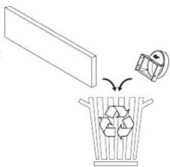
natural_image
Illustration of a plastic bin with recycling symbols inside, showing an open lid and a recycling bin (no text or labels)Parts Supplied
Check that all parts are included.
Air Filter (PN# W10748931)
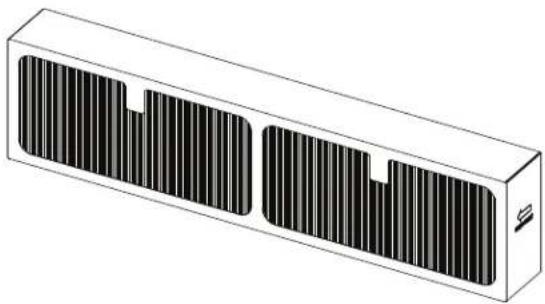
natural_image
Isometric illustration of a rectangular device with two side slats and a small protrusion (no text or symbols)■ Lower Filter Enclosure
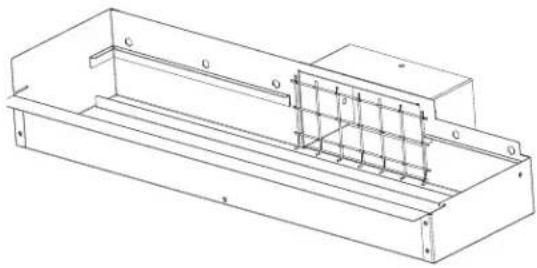
natural_image
Technical line drawing of a structural frame with internal supports and mounting points (no text or symbols)Parts Needed
To order, see the "Assistance or Service" section of the Use and Care Guide:
- Aluminum foil tape
Check local codes and consult gas supplier. Check existing gas supply and electrical supply. See the appropriate “Electrical Requirements” and “Gas Supply Requirements” sections.
It is recommended that all electrical connections be made by a licensed, qualified electrical installer.
Optional Parts
To purchase these or any other accessories, please reference the "Accessories" section of the Use and Care Guide for contact information.
Side Trim Kits:
^5/8 " (1.7 cm) Black – Order Part Number W10675026
^5/8 " (1.7 cm) Stainless Steel – Order Part Number W10675028
1½" (2.9 cm) Black – Order Part Number W10731886
1½" (2.9 cm) Stainless Steel – Order Part Number W10731887
■ Backsplash Kits:
High 6" (15.2 cm) Black – Order Part Number W10655449
High 6" (15.2 cm) Stainless Steel – Order Part Number W10655450
Location Requirements
IMPORTANT: Observe all governing codes and ordinances.
Do not obstruct flow of combustion and ventilation air.
It is the installer's responsibility to comply with installation clearances specified on the model/serial/rating plate. The model/serial/rating plate is located behind the oven door on the top right-hand side of the oven frame.
■ The range should be located for convenient use in the kitchen.
■ Recessed installations must provide complete enclosure of the sides and rear of the range.
To eliminate the risk of burns or fire by reaching over the heated surface units, cabinet storage space located above the surface units should be avoided. If cabinet storage is to be provided, the risk can be reduced by installing a range hood or microwave hood combination that projects horizontally a minimum of 5" (12.7 cm) beyond the bottom of the cabinets.
■ All openings in the wall or floor where range is to be installed must be sealed.
■ Cabinet opening dimensions that are shown must be used. Given dimensions are minimum clearances.
The anti-tip bracket must be installed. To install the anti-tip bracket shipped with the range, see "Install Anti-Tip Bracket" section.
■ Grounded electrical supply is required. See the appropriate "Electrical Requirements" section.
■ Proper gas supply connection must be available. See “Gas Supply Requirements” section.
■ Contact a qualified floor covering installer to check that the floor covering can withstand at least 200°F (93°C).
■ Use an insulated pad or 14 " (0.64 cm) plywood under range if installing range over carpeting.
IMPORTANT: To avoid damage to your cabinets, check with your builder or cabinet supplier to make sure that the materials used will not discolor, delaminate, or sustain other damage. This oven has been designed in accordance with the requirements of UL and CSA International and complies with the maximum allowable wood cabinet temperatures of 194°F (90°C).
Mobile Home – Additional Installation Requirements
The installation of this range must conform to the Manufactured Home Construction and Safety Standard, Title 24 CFR, Part 3280 (formerly the Federal Standard for Mobile Home Construction and Safety, Title 24, HUD Part 280). When such standard is not applicable, use the Standard for Manufactured Home Installations, ANSI A225.1/NFPA 501A or with local codes.
In Canada, the installation of this range must conform with the current standards CAN/CSA-A240-latest edition or with local codes.
Mobile Home Installations Require:
■ When this range is installed in a mobile home, it must be secured to the floor during transit. Any method of securing the range is adequate as long as it conforms to the standards listed above.
- Four-wire power supply cord or cable must be used in a mobile home installation. The appliance wiring will need to be revised. See “Electrical Requirements – U.S.A. Only” section.
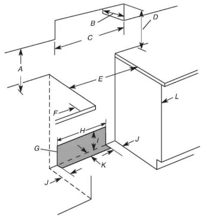
Product Dimensions
This manual covers several models. Your model may appear different from the models depicted. Dimensions given are maximum dimensions across all models.
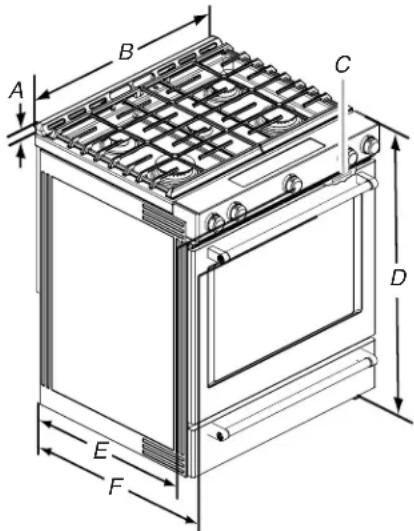
A. 1^3/16 (3.0 cm) height from cooktop to top of vent
B. 29 ^7 / _8 " (75.9 cm)
C. Model/serial/rating plate (located behind the oven door on the top right-hand side of the oven frame)
D. 36" (91.4 cm) height to top of cooktop edge with leveling legs screwed in all the way*
E.28 ^5/_16 " (71.9 cm) max. depth from front of console to back of range
F.28 ^7/8 " (73.3 cm) max. depth from handle to back of range
IMPORTANT: Range must be level after installation. Follow the instructions in the "Level Range" section. Using the cooktop as a reference for leveling the range is not recommended.
* Range can be raised approximately 1" (2.5 cm) by adjusting the leveling legs.
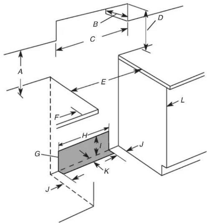
Cabinet Dimensions
Cabinet opening dimensions shown are for 25" (64.0 cm) countertop depth, 24" (61.0 cm) base cabinet depth and 36" (91.4 cm) countertop height.
IMPORTANT: If installing a range hood or microwave hood combination above the range, follow the range hood or microwave hood combination installation instructions for dimensional clearances above the cooktop surface.
Range may be installed next to combustible walls with zero clearance.
NOTE: When installed in a slide-in cutout, the front of oven door may protrude beyond the base cabinet.
Slide-in Cutout Freestanding Cutout
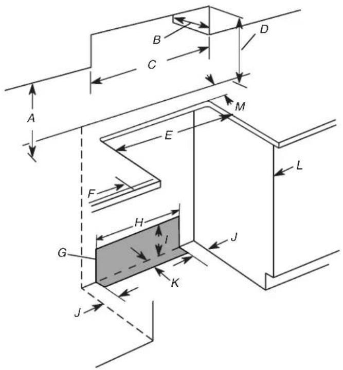
A. 18" (45.7 cm) upper side cabinet to countertop
B. 13" (33 cm) max. upper cabinet depth
C. 30" (76.2 cm) min. opening width
D. For minimum clearance to top of cooktop, see NOTE*.
E. 30" (76.2 cm) min. opening width
F. 3" (7.6 cm) min. clearance from both sides of range to side wall or other combustible material
G. The shaded area is recommended for installation of rigid gas pipe and grounded outlet.
H. 20 ^3 / 8 " (51.8 cm)
1. 7 ^11/16 " (19.5 cm)
J. 4 ^13 / 16 (12.2 cm)
K. 3 ^11/16 " (9.4 cm) plus measurement of M
L. Cabinet door or hinges should not extend into the cutout.
M. Remaining counter depth should not exceed 2½" (5.7 cm).
A. 18" (45.7 cm) upper side cabinet to countertop
B. 13" (33 cm) max. upper cabinet depth
C. 30" (76.2 cm) min. opening width
D. For minimum clearance to top of cooktop, see NOTE*.
E. 30" (76.2 cm) min. opening width
F. 3" (7.6 cm) min. clearance from both sides of range to side wall or other combustible material
G. The shaded area is recommended for installation of rigid gas pipe and grounded outlet.
H. 20 ^3 /8" (51.8 cm)
1. 7 ^11/16 " (19.5 cm)
J. 4 ^13/16 " (12.2 cm)
K. 3^11/_16 (9.4 cm)
L. Cabinet door or hinges should not extend into the cutout.
*NOTE: 24" (61.0 cm) minimum when bottom of wood or metal cabinet is shielded by not less than 14 " (0.64 cm) flame retardant millboard covered with not less than No. 28 MSG sheet steel, 0.015" (0.4 mm) stainless steel, 0.024" (0.6 mm) aluminum or 0.020" (0.5 mm) copper.
30" (76.2 cm) minimum clearance between the top of the cooking platform and the bottom of an uncovered wood or metal cabinet.
Electrical Requirements – U.S.A. Only
WARNING

Electrical Shock Hazard
Electrically ground range.
Failure to do so can result in death, fire, or electrical shock.
Be sure that the electrical connection and wire size are adequate and in conformance with the National Electrical Code, ANSI/ NFPA 70-latest edition and all local codes and ordinances.
A copy of the above code standards can be obtained from:
National Fire Protection Association
1 Batterymarch Park
Quincy, MA 02169-7471
WARNING: Improper connection of the equipment-grounding conductor can result in a risk of electric shock. Check with a qualified electrician or service technician if you are in doubt as to whether the appliance is properly grounded. Do not modify the power supply cord plug. If it will not fit the outlet, have a proper outlet installed by a qualified electrician.
Electrical Connection
Check local codes and consult gas supplier. Check existing electrical supply and gas supply. See “Gas Supply Requirements” section.
It is recommended that all electrical connections be made by a licensed, qualified electrical installer.
Range must be connected to the proper electrical voltage and frequency as specified on the model/serial/rating plate. The model/serial/rating plate is located on the right vertical surface of the oven door frame. Refer to the illustrations in the "Product Dimensions" section of the "Location Requirements" section.
This range is manufactured with a 4-wire power supply cord rated at 240 volts, 40 amps, rated at 194°F (90°C) and investigated for use with this range.
| Range Rating* | Specified Rating of Power Supply Cord Kit and Circuit Protection |
| 120/240 Volts 120/208 Volts Amps Temp Rating | |
| 8.8–16.5 kW 7.8–12.5 kW 40 or 50 194°F (90°C) | |
| 16.6–22.5 kW 12.6–18.5 kW 50 194°F (90°C) | |
* The NEC calculated load is less than the total connected load listed on the model/serial/rating plate.
When a 4-wire, single phase 240 volt, 60 Hz., AC only electrical supply is available, a 40-amp minimum circuit protection is required on 30" (76.2 cm) ranges, fused on both sides of the line.
■ A time-delay fuse or circuit breaker is recommended.
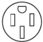
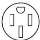
This range is equipped with a UL or CSA International Certified Power Cord intended to be plugged into a standard 14-50R wall receptacle. Be sure the wall receptacle is within reach of range's final location.
■ Do not use an extension cord.
■ The wiring diagram is located on the back of the range or in a clear plastic bag.
Electrical Requirements – Canada Only
WARNING

Electrical Shock Hazard
Electrically ground range.
Failure to do so can result in death, fire, or electrical shock.
Be sure that the electrical connection and wire size are adequate and in conformance with the CSA Standard C22.1, Canadian Electrical Code, Part 1 – latest edition, and all local codes and ordinances.
A copy of the above code standards can be obtained from:
Canadian Standards Association
178 Rexdale Blvd.
Toronto, ON M9W 1R3 CANADA
- Check with a qualified electrical installer if you are not sure the range is properly grounded.
Range Rating\*
Specified Rating of Power Supply Cord Kit and Circuit Protection
120/240 Volts 120/208 Volts Amps Temp Rating
8.8–16.5 kW 7.8–12.5 kW 40 or 50 194°F (90°C)
16.6–22.5 kW 12.6–18.5 kW 50 194°F (90°C)
* The NEC calculated load is less than the total connected load listed on the model/serial/rating plate.
When a 4-wire, single phase 240 volt, 60 Hz., AC only electrical supply is available, a 40-amp minimum circuit protection is required on 30" (76.2 cm) ranges, fused on both sides of the line.
■ A time-delay fuse or circuit breaker is recommended.
This range is equipped with a UL or CSA International Certified Power Cord intended to be plugged into a standard 14-50R wall receptacle. Be sure the wall receptacle is within reach of range's final location.
■ Do not use an extension cord.
■ The wiring diagram is located on the back of the range or in a clear plastic bag.
Gas Supply Requirements
WARNING
Explosion Hazard
Use a new CSA International approved gas supply line. Install a shut-off valve.
Securely tighten all gas connections.
If connected to LP, have a qualified person make sure gas pressure does not exceed 14" (36 cm) water column.
Examples of a qualified person include: licensed heating personnel, authorized gas company personnel, and authorized service personnel.
Failure to do so can result in death, explosion, or fire.
Observe all governing codes and ordinances.
IMPORTANT: This installation must conform with all local codes and ordinances. In the absence of local codes, installation must conform with American National Standard, National Fuel Gas Code ANSI Z223.1 – latest edition or CAN/CGA B149 – latest edition.
IMPORTANT: Leak testing of the range must be conducted according to the manufacturer's instructions.
Type of Gas
Natural Gas:
This range is design-certified by CSA International for use with Natural gas or, after proper conversion, for use with LP gas.
This range is factory-set for use with Natural gas. See “Gas Conversions” section. The model/serial/rating plate located on the oven frame behind the top right-hand side of the oven door has information on the types of gas that can be used. If the types of gas listed do not include the type of gas available, check with the local gas supplier.
LP Gas Conversion:
Conversion must be done by a qualified service technician. No attempt shall be made to convert the appliance from the gas specified on the model/serial/rating plate for use with a different gas without consulting the serving gas supplier. See “Gas Conversions” section.
Gas Supply Line
■ Provide a gas supply line of 34 " (1.9 cm) rigid pipe to the range location. A smaller size pipe on longer runs may result in insufficient gas supply. With LP gas, piping or tubing size can be 12 " (1.3 cm) minimum. Usually, LP gas suppliers determine the size and materials used in the system.
NOTE: Pipe-joint compounds that resist the action of LP gas must be used. Do not use TEFLON ^®† tape.
†®TEFLON is a registered trademark of E.I. Du Pont De Nemours and Company.
Flexible Metal Appliance Connector:
If local codes permit, a new CSA design-certified, 4 to 5 ft (122 to 152.4 cm) long, 12 " or 34 " (1.3 or 1.9 cm) I.D. (inside diameter), flexible metal appliance connector may be used for connecting range to the gas supply line.
A 12 " (1.3 cm) male pipe thread is needed for connection to the female pipe threads of the inlet to the appliance pressure regulator.
■ Do not kink or damage the flexible metal tubing when moving the range.
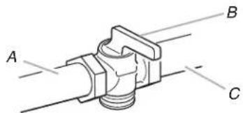
■ Must include a shut-off valve:
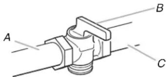
The supply line must be equipped with a manual shut-off valve. This valve should be located in the same room but external to the range opening, such as an adjacent cabinet. It should be in a location that allows ease of opening and closing. Do not block access to shut-off valve. The valve is for turning on or shutting off gas to the range.
A. Gas supply line
B. Shut-off valve "open" position
C. To range
Gas Pressure Regulator
The gas pressure regulator supplied with this range must be used. The inlet pressure to the regulator should be as follows for proper operation:
Natural Gas:
Minimum pressure: 5" WCP
Maximum pressure: 14" WCP
LP Gas:
Minimum pressure: 11" WCP
Maximum pressure: 14" WCP
Contact local gas supplier if you are not sure about the inlet pressure.
Burner Input Requirements
Input ratings shown on the model/serial/rating plate are for elevations up to 2,000 ft (609.6 m).
For elevations above 2,000 ft (609.6 m), ratings are reduced at a rate of 4% for each 1,000 ft (304.8 m) above sea level (not applicable for Canada).
Gas Supply Pressure Testing
Gas supply pressure for testing regulator must be at least 1" (2.5 cm) water column pressure above the manifold pressure shown on the model/serial/rating plate.
Line Pressure Testing Above 12 psi Gauge (14" WCP)
The range and its individual shut-off valve must be disconnected from the gas supply piping system during any pressure testing of that system at test pressures in excess of 12 psi (3.5 kPa).
Line Pressure Testing at 12 psi Gauge (14" WCP) or Lower
The range must be isolated from the gas supply piping system by closing its individual manual shut-off valve during any pressure testing of the gas supply piping system at test pressures equal to or less than 12 psi (3.5 kPa).
INSTALLATION INSTRUCTIONS
Unpack Range
WARNING
Excessive Weight Hazard
Use two or more people to move and install range.
Failure to do so can result in back or other injury.
- Remove shipping materials, tape and film from the range. Keep cardboard bottom under range. Do not dispose of anything until the installation is complete.
- Remove oven racks and parts package from oven and shipping materials.
- To remove cardboard bottom, first take 4 cardboard corners from the carton. Stack one cardboard corner on top of another. Repeat with the other 2 corners. Place them lengthwise on the floor behind the range to support the range when it is laid on its back.
- Using 2 or more people, firmly grasp the range and gently lay it on its back on the cardboard corners.
- Remove cardboard bottom.
The leveling legs can be adjusted while the range is on its back. See the “Adjust Leveling Legs” section.
NOTE: To place range back up into a standing position, put a sheet of cardboard or hardboard on the floor in front of range to protect the flooring. Using 2 or more people, stand range back up onto the cardboard or hardboard.
Adjust Leveling Legs
- If range height adjustment is necessary, use a wrench or pliers to loosen the 4 leveling legs.
This may be done with the range on its back or with the range supported on 2 legs after the range has been placed back to a standing position.
NOTE: To place range back up into a standing position, put a sheet of cardboard or hardboard in front of range. Using 2 or more people, stand range back up onto the cardboard or hardboard.
WARNING

natural_image
Silhouette of a person pushing a large block on a horizontal line (no text or symbols)Tip Over Hazard
A child or adult can tip the range and be killed.
Install anti-tip bracket to floor or wall per installation instructions.
Slide range back so rear range foot is engaged in the slot of the anti-tip bracket.
Re-engage anti-tip bracket if range is moved.
Do not operate range without anti-tip bracket installed and engaged.
Failure to follow these instructions can result in death or serious burns to children and adults.
- Measure the distance from the top of the counter to the floor.
- Measure the distance from the top of the cooktop to the bottom of the leveling legs. This distance should be the same. If it is not, adjust the leveling legs to the correct height. The leveling legs can be loosened to add up to a maximum of 1" (2.5 cm). A minimum of 316 " (5 mm) is needed to engage the anti-tip bracket.
NOTE: If height adjustment is made when range is standing, tilt the range back to adjust the front legs, and then tilt forward to adjust the rear legs. - When the range is at the correct height, check that there is adequate clearance under the range for the anti-tip bracket. Before sliding range into its final location, check that the anti-tip bracket will slide under the range and onto the rear leveling leg prior to anti-tip bracket installation.
NOTE: If a Trim Kit will be used, the top of the cooktop should be higher than the counter. See the Installation Instructions included with the Trim Kit for the correct height.
Install Anti-Tip Bracket
WARNING
natural_image
Silhouette of a person pushing a large block on a horizontal line (no text or symbols)Tip Over Hazard
A child or adult can tip the range and be killed.
Install anti-tip bracket to floor or wall per installation instructions.
Slide range back so rear range foot is engaged in the slot of the anti-tip bracket.
Re-engage anti-tip bracket if range is moved.
Do not operate range without anti-tip bracket installed and engaged.
Failure to follow these instructions can result in death or serious burns to children and adults.
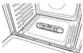
- Remove the anti-tip bracket from the inside of the oven.
- Determine which mounting method to use: floor or wall.
If you have a stone or masonry floor, you can use the wall mounting method. If you are installing the range in a mobile home, you must secure the range to the floor.
This anti-tip bracket and screws can be used with wood or metal studs.
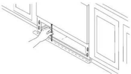
- Determine and mark center line of the cutout space. The mounting bracket can be installed on either the left-hand or right-hand side of the cutout. Position mounting bracket against the wall in the cutout so that the V-notch of the bracket is 12½" (31.8 cm) from center line as shown.
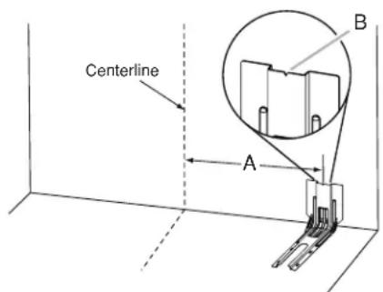
A. 12½" (31.8 cm)
B. Bracket V-notch
- Drill two 18 " (3 mm) holes that correspond to the bracket holes of the determined mounting method. See the following illustrations.
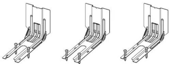
Floor Mounting
natural_image
Three technical line drawings of metal bracket assemblies with mounting holes (no text or symbols)Rear position Front position Diagonal (2 options)
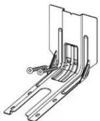
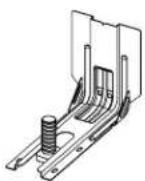
Wall Mounting
natural_image
Technical line drawing of a mechanical bracket or mounting bracket (no text or symbols)- Using the two #10 x 1 ^5/8 " (4.1 cm) Phillips-head screws provided, mount anti-tip bracket to the wall or floor.
- Move range close enough to opening to allow for final electrical connections. Remove shipping base, cardboard or hardboard from under range.
- Move range into its final location, making sure rear leveling leg slides into anti-tip bracket.
- Move range forward onto shipping base, cardboard or hardboard to continue installing the range, using the following installation instructions.
Install Recirculation Blower Assembly
Items Needed:
■ Blower Assembly (located under range)
■ Lower Filter Enclosure
■ (3) Felt Pads
■ (3) #10 x 1" screws
■ Aluminum tape
The anti-tip bracket must be installed. To install the anti-tip bracket shipped with the range, see "Install Anti-Tip Bracket" section.
Assemble Recirculation Housing
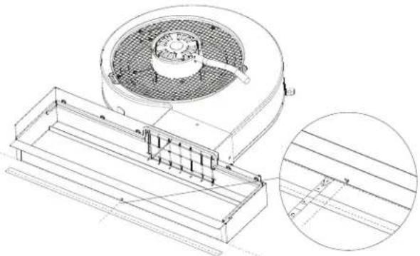
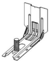
- Slide the Lower Filter Enclosure over the blower assembly outlet.
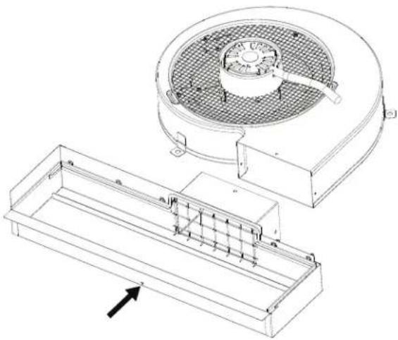
natural_image
Technical line drawing of a mechanical device with a fan and housing, showing internal components and a directional arrow (no text or symbols)- Secure the Lower Filter Enclosure to the blower motor with the three (3) #8 - 3/8" screws provided. Seal connection with aluminum tape.
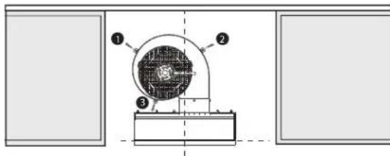
Position the Blower
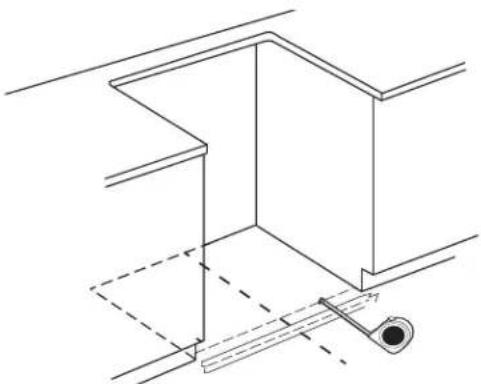
- Determine and mark the center line on the floor of the cabinet opening.
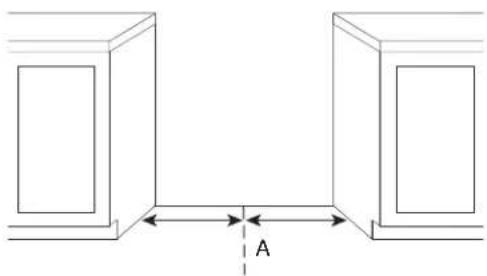
natural_image
Pure architectural line drawing of two symmetrical structures with a central horizontal dimension labeled 'A' (no text or symbols beyond the label)A. Center line
- Without blower or service connections installed, fit the range in its final installation position.
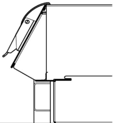
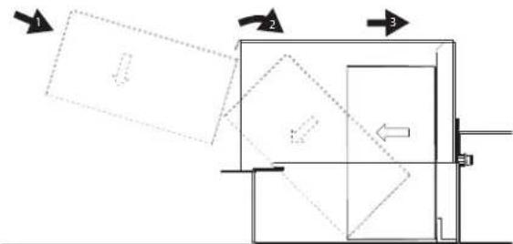
- Remove the Front Lower Access Panel of the range by gently lifting on the panel; then pull outward.
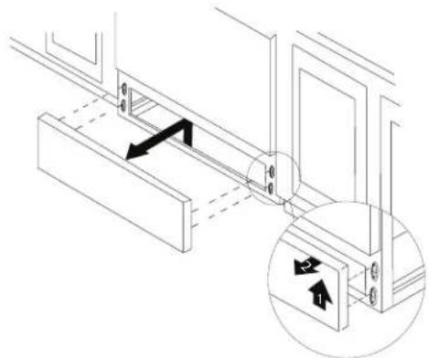
natural_image
Technical line drawing of a mechanical assembly with an inset showing directional arrows (no text or symbols)- Place level on the oven bottom, as indicated in one of the two figures below, depending on the size of the level. Check with the level side to side and front to back. If range is not level, use a wrench or pliers to adjust leveling legs up or down until the range is level.
NOTE: Range must be level for satisfactory baking performance and best cleaning results using AquaLift® Self-Clean Technology.
natural_image
Diagram of a microwave oven interior showing the lid and vent (no text or symbols)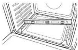
natural_image
Line drawing of a door with a horizontal bar inside, showing interior space and window (no text or symbols)- Place a strip of masking tape on the floor, in front of the lower front frame, and mark a line flush with the front of the frame.
NOTE: Be sure to keep the line even with the front frame.
natural_image
Line drawing of a hand adjusting a wall-mounted bracket (no text or symbols)- Remove the range from opening. Be sure not to remove tape during range removal.
- Offset the line marked in step 4 by 1 12 (3.8 cm) towards the rear of the range opening.
natural_image
Pure technical line drawing of a structural frame with no text, numbers, or symbols- Remove three felt pads from the gasket strip (found in the blower accessory kit).
- Remove the paper backing from the felt pads and apply to the bottom of the three (3) blower motor tabs.
NOTE: Felt pads reduce motor noise and aid in mounting to uneven floors.
- Position the blower assembly from "Assemble Recirculation Housing" so the front edge of the Lower Filter Enclosure is aligned with the mark made in step 4. Align the center mark of the Lower Filter Enclosure with the center line previously marked on the floor.
natural_image
Technical line drawing of a mechanical component with internal structure and cross-sectional view (no text or symbols)Secure the Blower
- Drill three 1/8" (3 mm) pilot holes using the blower motor tabs as guides.
- Mount the blower motor to the floor with the three #10 x 1" screws provided.
NOTE: If the range height adjustment is significant, the blower may need to be shimmed to ensure proper installation.
- Remove masking tape from floor.
Install Blower
Install Blower Cover
- Locate blower motor cover.
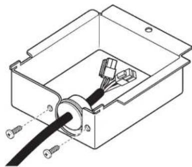
- Run the blower motor wires with strain relief through the small opening in the blower motor cover, starting from the inside and feeding out.
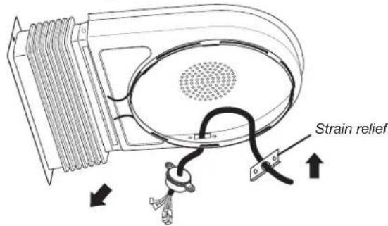
- Feed blower motor wire through opening and place the strain relief bracket to the inside of the blower cover. Install and tighten the two (2) provided #8-18 x 38 " screws to secure the strain relief bracket.
natural_image
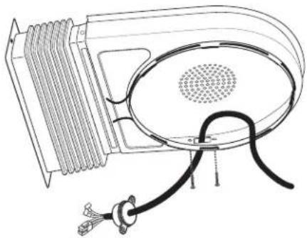
Technical line drawing of a mechanical device with coiled cable and ventilation slots (no text or symbols)- Reposition the blower motor cover retainer spring as illustrated.
natural_image
Diagram of a heat exchanger or cooling unit with heat flow arrows and a sensor device (no text or labels)- Remove paper from the rear of the rectangular felt pad and apply adhesive side of felt to the bellow flange.
NOTE: This step is important to ensure maximum blower performance.
natural_image
Diagram of a curved mechanical component with two arrows indicating force or movement (no text or symbols)- Apply blower motor cover to the blower. Slightly spread the cover retainer spring to allow the cover to drop into position on the blower motor. Ensure the blower cover retainer ring is securely locked in place.
NOTE: The blower motor cover will not properly install if the motor wire is on the top of the motor.
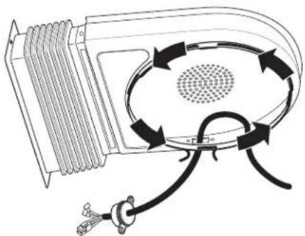
- Rotate blower motor cover so the bellows are facing towards the right of the installation and position the bellows so the bellow flange is facing the floor as illustrated.
natural_image
Line drawing of a mechanical setup with a fan-shaped component and a base, no text or symbols present- Move blower motor wire to the front of the installation.
Make Utility Connections
Make Gas Connection
WARNING
Explosion Hazard
Use a new CSA International approved gas supply line.
Install a shut-off valve.
Securely tighten all gas connections.
If connected to LP, have a qualified person make sure gas pressure does not exceed 14" (36 cm) water column.
Examples of a qualified person include:
licensed heating personnel, authorized gas company personnel, and authorized service personnel.
Failure to do so can result in death, explosion, or fire.
This range is factory-set for use with Natural gas. To use this range with LP gas, see the “Gas Conversions” section before connecting this range to the gas supply. Gas conversions from Natural gas to LP gas or from LP gas to Natural gas must be done by a qualified installer.
Typical Flexible Connection
- Apply pipe-joint compound made for use with LP gas to the smaller thread ends of the flexible connector adapters. See B and G in the following illustration.
- Attach one adapter to the gas pressure regulator and the other adapter to the gas shut-off valve. Tighten both adapters, being certain not to move or turn the gas pressure regulator.
- Use a^15/16 " (2.4 cm) combination wrench and an adjustable wrench to attach the flexible connector to the adapters.
IMPORTANT: All connections must be wrench-tightened. Do not make connections to the gas regulator too tight. Making the connections too tight may crack the regulator and cause a gas leak. Do not allow the regulator to turn when tightening fittings.
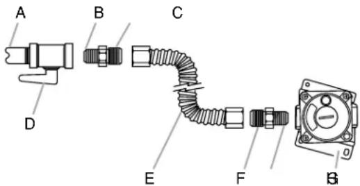
A. 12 " (1.3 cm) or 34 " (1.9 cm) gas pipe
B. Use pipe-joint compound.
C. Adapter
D. Manual gas shut-off valve
E. Flexible connector
F. Adapter (must have 12 " [1.3 cm] male pipe thread)
G. Use pipe-joint compound.
H. Gas pressure regulator
Complete Connection
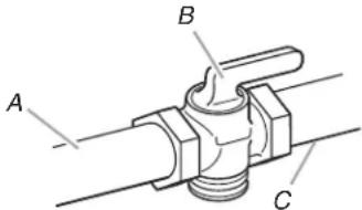
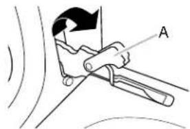
- Open the manual shut-off valve in the gas supply line. The valve is open when the handle is parallel to the gas pipe.
A. Closed valve
B. Open valve
- Test all connections by brushing on an approved noncorrosive leak-detection solution. If bubbles appear, a leak is indicated. Correct any leak found.
Connect Blower Assembly to Range
- Remove the cardboard or hardboard from under the range.
- Using 2 or more people, gently move the range into its final location.
- Ensure the front edge of the Lower Filter Enclosure is above the lower front frame cross support.
natural_image
Technical line drawing of a mechanical assembly or bracket (no text or symbols)NOTE: If the Lower Filter Enclosure is below the Lower Front Frame Cross Support, the blower may need to be shimmed.
- Check to ensure the flexible metal gas connector and electrical cord are not kinked. Use a flashlight to look underneath the bottom of and behind the range.
- Verify that the anti-tip bracket is installed and engaged.
a. Use a flashlight to look underneath the bottom of and behind the range.
b. Visually check that the rear range foot is inserted into the slot of the anti-tip bracket.
- Visually check that there is an air gap between the Blower Motor Cover and the bottom of the range to ensure proper blower motor ventilation.
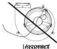
- Rotate blower motor cover so the bellows are in their final position. Ensure the rear of the bellow flange is engaged in the retaining bracket.
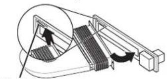
natural_image
Diagram of a mechanical device with a magnified inset showing internal components (no text or symbols)Retaining bracket
natural_image
Technical line drawing of a mechanical component with a circular feature and textured body (no text or symbols)Final position
8 Secure the front of the blower bellow flange to the range frame with the supplied #8-18 x 3/8" screw.
Connect Blower Electrical Parts
- Locate the capacitor (in Blower Motor Kit).
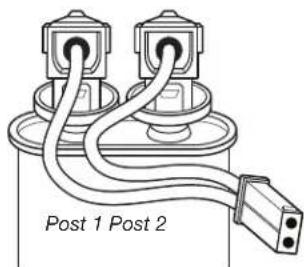
NOTE: The capacitor is supplied with a small harness that terminates in a two-pin connector as shown.
- Locate the capacitor storage tray in front of the blower bellow connection point in the lower right side of the range.
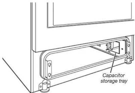
- Place capacitor in tray.
- Secure the capacitor with the capacitor retention bracket; then install the bracket screw.
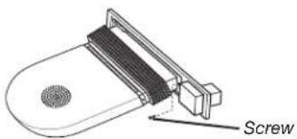
- Secure the blower motor strain relief, near the quick connection end, to the blower electrical terminal cover with the two provided screws.
natural_image
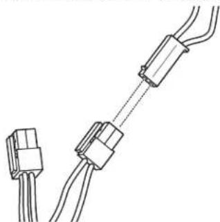
Technical line drawing of an electrical connector with wires and connectors (no text or symbols)- Locate the two-pin connector on the blower motor wire harness and connect it to the two-pin capacitor connector.
natural_image
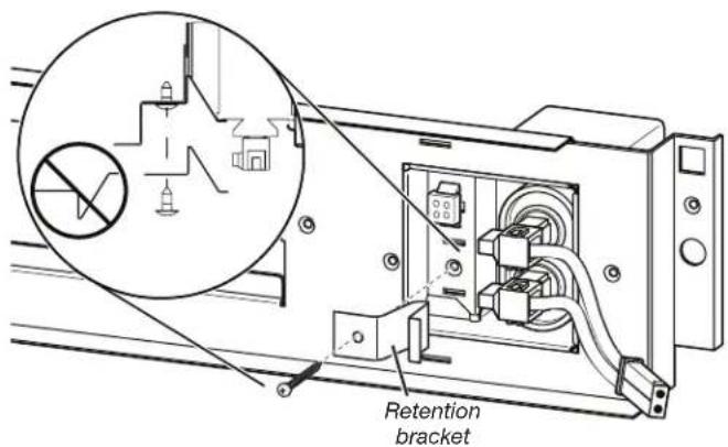
Pure electrical connector diagram showing two terminal blocks connected by wires (no text or symbols)- Locate the 4-pin connector on the blower motor wire and plug it into the terminal connection point directly behind the capacitor storage tray.
NOTE: The terminal release (clip point) will be facing toward the front of the range.

natural_image
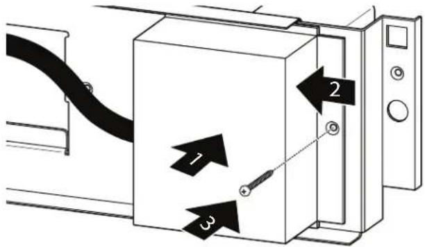
Technical line drawing of an electrical enclosure with wiring and connectors (no text or symbols)- Install blower electrical terminal cover.
NOTE: When replacing cover, insert the terminal cover tabs in the corresponding slots in the range, and push the terminal cover rearward to engage.
- Install terminal cover screw.
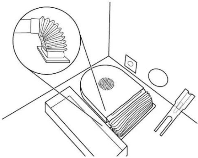
Complete Filter Assembly
You Will Need
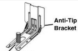
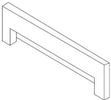
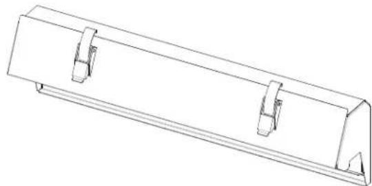
■ Upper Filter Enclosure
■ (5) M5 X 15 mm Screws
■ 8" Phillips Screwdriver
Air Filter
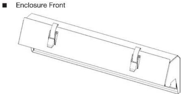
■ Enclosure Front
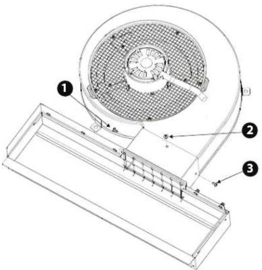
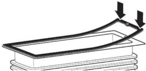
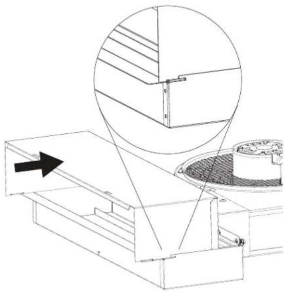
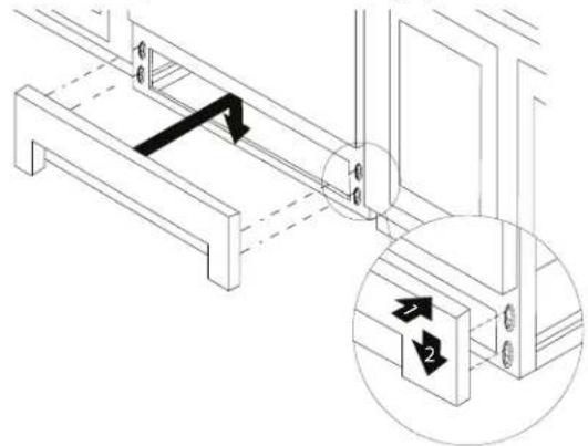
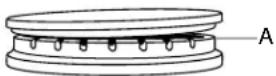
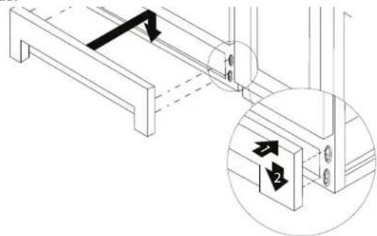
- Attach the Upper Filter Enclosure to the Lower Filter Enclosure by sliding the Upper Filter Enclosure straight back into the Lower Filter Enclosure.
The final position of the Upper Filter Enclosure is to be resting on the back shelf of the Lower Filter Enclosure with the tabs of the Upper Filter Enclosure engaged in the Lower Filter Enclosure.
natural_image
Technical line drawing of a mechanical assembly with an inset showing a close-up of a structural detail (no text or symbols present)NOTE: Cabinets and range removed from image for clarification.
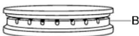
- Using five (5) M5 x 15 mm screws, securely fasten the Upper Filter Enclosure to the Lower Filter Enclosure.
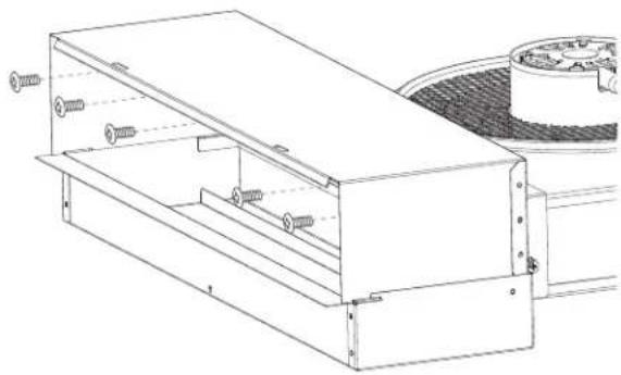
natural_image
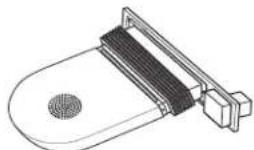
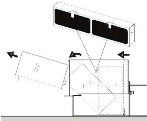
Technical line drawing of a mechanical assembly with screws and a housing (no text or symbols)- Install Air Filter into the housing and then rotate it to its final position.
NOTE: Confirm the Air Flow indicator, marked on the Air Filter, points toward the front of the range.
Side View of Assembled Filter Housing
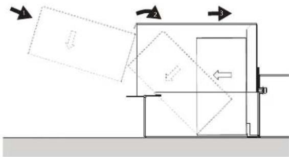
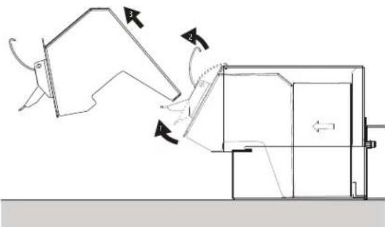
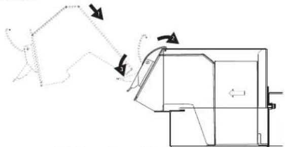
- Install the Enclosure Front by slightly tilting it towards you, placing in the housing, and rotating it up into the final position.
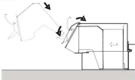
natural_image
Technical line drawing of a mechanical device emitting motion arrows (no text or symbols)Side View of Assembled Filter Housing
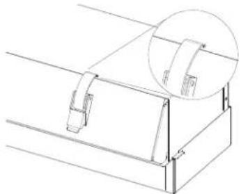
- Latch the Enclosure Front to the housing by positioning the front clasps in the slots on the top of the housing; then, push down on the clasp handles.
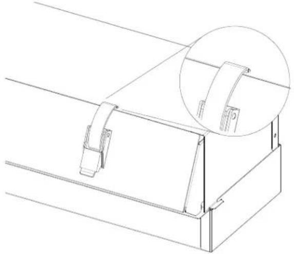
natural_image
Technical line drawing of a mechanical bracket assembly with an inset magnified detail (no text or symbols)- Install the new Front Lower Access Panel that shipped with the duct-free kit, by aligning the studs with the keyhole slots on the range. Press the Front Lower Access Panel forward into the slots and push downward to engage the studs.
- See "Replacing Air Filter" section for servicing.
Make Electrical Connection
Plug into grounded outlet. See the appropriate "Electrical Requirements" section.
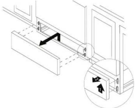
Verify Anti-Tip Bracket Is Installed and Engaged
- Ensure range is in its final location.
- Remove the front lower access panel.
- Use a flashlight to look underneath the bottom of the range.
- Visually check that the rear range foot is inserted into the slot of the anti-tip bracket.
- Replace the front lower access panel.
IMPORTANT: If the range is moved to adjust the leveling legs, verify that the anti-tip bracket is engaged by repeating steps 1 to 5.
Oven Door
For normal range use, it is not suggested to remove the oven door. However, if removal is necessary, make sure the oven is off and cool. Then follow these instructions. NOTE: The oven door is heavy.
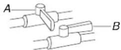
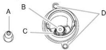
To Remove:
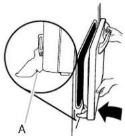
- Open oven door all the way.
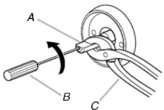
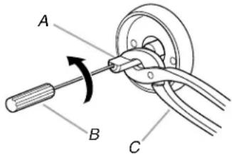
- Pinch the hinge latch between two fingers and pull forward. Repeat on other side of oven door.
natural_image
Mechanical diagram showing a lever mechanism with labeled point A (no text or symbols present)A. Hinge latch
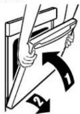
- Close the oven door as far as it will shut.
- Lift the oven door while holding both sides.
Continue to push the oven door closed and pull it away from the oven door frame.
To Replace:
- Insert both hanger arms into the door. Be sure that the hinge notches are engaged in the oven door frame.
A. Hinge notch
- Open the oven door. The door should be able to open all the way.
- Move the hinge levers back to the locked position. Check that the door is free to open and close and is level while closed. If it is not, repeat the removal and installation procedures.
Complete Installation
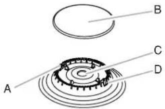
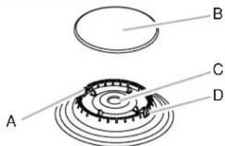
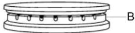
- Remove cooktop burner caps and bases from package containing parts. Place the burner bases as indicated by the following illustration:
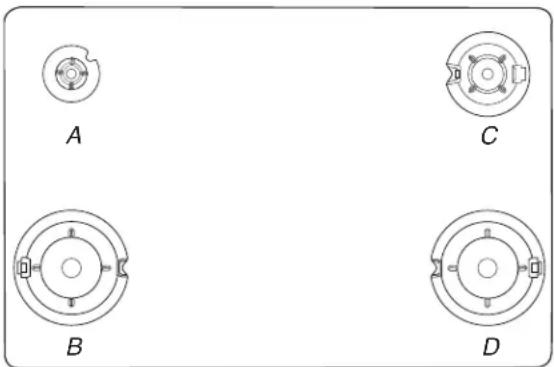
natural_image
Four circular mechanical components labeled A, B, C, D, with no visible text or symbols on the parts themselves.A. Small
C. Medium
B. Large
D. Large
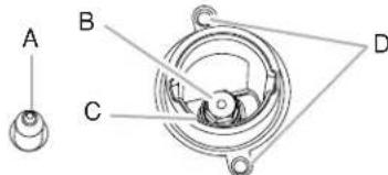
- Align the gas tube opening in the burner base with the orifice holder on the cooktop and the igniter electrode with the notch in the burner base.
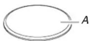
A. Burner cap
B. Gas tube opening
C. Burner base
D. Igniter electrode
E. Orifice holder
- Place the burner caps on the appropriate burner bases.
IMPORTANT: The bottom of the small and medium caps are different. Do not put the wrong size burner cap on the burner base.


Small cap Medium cap Large cap
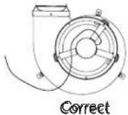
Burner caps should be level when properly positioned. If burner caps are not properly positioned, surface burners will not light. The burner cap should not rock or wobble when properly aligned.
A. Incorrect
B. Correct
- Place burner grates over burners and caps.
- Check to ensure the flexible metal gas connector and electrical cord are not kinked. Use a flashlight to look underneath the bottom of and behind the range.
- Check that all parts are now installed. If there is an extra part, go back through the steps to see which step was skipped.
- Check that you have all of your tools.
- Check that you have all of the range accessories, especially oven racks. These accessories may be in the range packaging.
- Dispose of/recycle all packaging materials.
- Check that the range is level. See the "Level Range" section.
- Use a mild solution of liquid household cleaner and warm water to remove waxy residue caused by shipping material. Dry thoroughly with a soft cloth. For more information, see the "Range Care" section of the Use and Care Guide.
- Read the Use and Care Guide.
- Turn on surface burners and oven. Confirm surface burner flame height by reviewing the "Adjust Flame Height" section, and adjust flame if necessary. See the Use and Care Guide for instructions on range operation.
NOTE: Odors and smoke are normal when the oven is used the first few times.
If Range Does Not Operate, Check the Following:
■ Household fuse is intact and tight, or circuit breaker has not tripped.
■ Gas pressure regulator shut-off valve is in the open position.
■ Range is plugged into a grounded outlet.
■ Electrical supply is connected.
IMPORTANT: If the range control displays an "F9" or "F9, E0" error code, the electrical outlet in the home may be miswired. Disconnect power and contact a qualified electrician to verify the electrical supply.
- When the range has been on for 5 minutes, check for heat. If the range is cold, turn off the range and check that the gas supply line shut-off valve is open.
■ If the gas supply line shut-off valve is closed, open it, and then repeat the 5-minute test as outlined above.
■ If the gas supply line shut-off valve is open, close it, and contact a qualified technician.
Initial Lighting and Gas Flame Adjustments
Standard Surface Burners
Push in and turn each control knob to the ignite position.
The flame should light within 4 seconds. The first time a burner is lit, it may take longer than 4 seconds to light because of air in the gas line.
If Burners Do Not Light Properly:
■ Turn cooktop control knob to the off position.
- Check that the range is plugged into a grounded 3-prong outlet. Check that the circuit breaker has not tripped or the household fuse has not blown.
- Check that the gas shut-off valves are set to the open position.
- Check that burner caps are properly positioned on burner bases.
Repeat start-up. If a burner does not light at this point, turn the control knobs to the off position and contact your dealer or authorized service company for assistance. Please reference the "Warranty" section of the Use and Care Guide to contact service.
If the cooktop "low" burner flame needs to be adjusted for any of the burners, see the "Adjust Flame Height" section.
If You Need Assistance or Service:
Please reference the "Warranty" section of the Use and Care Guide to contact service.
Electronic Ignition System
Cooktop burners use electronic igniters in place of standing pilots. When the cooktop control knob is turned to the ignite position, the system creates a spark to light the burner. All cooktop burners will spark, but only the burner with the control knob turned to the ignite position will produce a flame. This sparking continues as long as the control knob is turned to the ignite position.
GAS CONVERSIONS
Gas conversions from Natural gas to LP gas or from LP gas to Natural gas must be done by a qualified installer.
WARNING
Explosion Hazard
Use a new CSA International approved gas supply line. Install a shut-off valve.
Securely tighten all gas connections.
If connected to LP, have a qualified person make sure gas pressure does not exceed 14" (36 cm) water column.
Examples of a qualified person include:
licensed heating personnel, authorized gas company personnel, and authorized service personnel.
Failure to do so can result in death, explosion, or fire.
LP Gas Conversion
WARNING

natural_image
Silhouette of a person pushing a large block on a horizontal line (no text or symbols)Tip Over Hazard
A child or adult can tip the range and be killed.
Install anti-tip bracket to floor or wall per installation instructions.
Slide range back so rear range foot is engaged in the slot of the anti-tip bracket.
Re-engage anti-tip bracket if range is moved.
Do not operate range without anti-tip bracket installed and engaged.
Failure to follow these instructions can result in death or serious burns to children and adults.
- Turn manual shut-off valve to the closed position.
A. To range
B. Shut-off valve (closed position)
C. Gas supply line
- Unplug range or disconnect power.
To Convert Gas Pressure Regulator (Natural Gas to LP Gas)
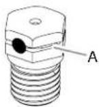
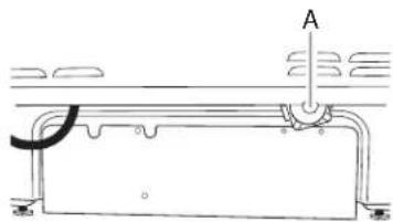
- Move the range out from the wall.
- Locate the gas pressure regulator at the lower right corner on the back of the range.
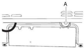
natural_image
Technical line drawing of a mechanical component with labeled point A (no text or symbols present)A. Gas pressure regulator
IMPORTANT: Do not remove the gas pressure regulator.
- Remove the front lower panel of the range.
- Disconnect the blower motor electrical connections.
- Disconnect the downdraft blower bellows from the range.
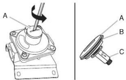
- Unscrew the metal cover and unscrew the blue regulator cap. Keep the washer in place.
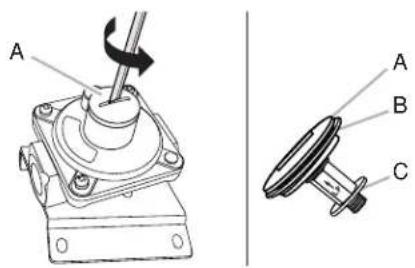
A. Metal cover
B. Washer
C. Blue regulator cap
- Flip the blue regulator cap over and screw it back into the metal cover.
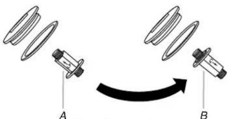
A. Natural gas position
B. LP gas position
- Screw the metal cover securely back into place. Do not overtighten.
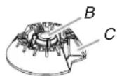
To Convert Surface Burners (Natural Gas to LP Gas)
- If installed, remove the burner grates.
- Remove the burner caps.
- Remove the burner base.
A. Igniter electrode
B. Burner cap
C. Gas tube opening
D. Burner base
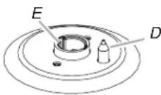
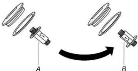
- Apply masking tape to the end of 32 " (7 mm) nut driver to help hold the gas orifice spud in the nut driver while changing it. Press nut driver down onto the gas orifice spud and remove by turning it counterclockwise and lifting out. Set gas orifice spud aside.
A. Igniter electrode
B. Orifice spud
C. Orifice spud holder D. Screws
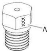
- Remove the orifice spuds shipped in the literature package in the oven. Gas orifice spuds are stamped with a number, marked with 1 or 2 color dots, and have a groove in the hex area. Replace the Natural gas orifice spud with the correct LP gas orifice spud.
A. LP groove
Refer to the following chart for correct LP gas orifice spud ratings and to spud holder card for proper placement.
LP Gas Orifice Spud Chart for Surface Burners
| Burner Rating/Type | Color Size (mm) | ID Number Placement | ||
| 15,000 BTU/Stacked* | Silver | 1.05 | L105 | LF |
| Black/Orange | 0.32 | L32 | ||
| 14,200 BTU/ Ultra/Stacked* | Silver 1.05 L105 LF/RF | |||
| 8,000 BTU/Semi | Red/Orange | 0.85 L85 RR/CTR | ||
| 5,000 BTU/Auxi | Red/Blue | 0.65 L65 LR | ||
| 1,200 BTU/Stacked/Simmer* | Black/Orange | 0.32 L32 LF (Simmer) | ||
*Not in all kits/models.
NOTE: Refer to the model/serial/rating plate located on the oven frame behind the top right-hand side of the oven door for proper sizing of spuds for each burner location.
- Place Natural gas orifice spuds in the orifice spud bag.
IMPORTANT: Keep the Natural gas orifice spuds in case of reinstallation with Natural gas.
- Replace the burner base.
- Replace burner cap.
- Repeat steps 1 to 7 for the remaining burners.
Complete Installation (Natural Gas to LP Gas)
- Refer to the "Make Gas Connection" section for proper connection of the range to the gas supply.
- Refer to the "Electronic Ignition System" section for proper burner ignition and operation.
- Refer to the "Adjust Flame Height" section for burner flame adjustments.
IMPORTANT: You may have to adjust the low setting for each cooktop burner.
Checking for proper cooktop burner flame is very important. Natural gas flames do not have yellow tips.
- Refer to "Complete Installation" in the "Installation Instructions" section of this manual to complete this procedure.
IMPORTANT: Make sure to save the orifices that have just been replaced in the conversion.
Natural Gas Conversion
WARNING

natural_image
Silhouette of a person pushing a large block on a horizontal line (no text or symbols)Tip Over Hazard
A child or adult can tip the range and be killed.
Install anti-tip bracket to floor or wall per installation instructions.
Slide range back so rear range foot is engaged in the slot of the anti-tip bracket.
Re-engage anti-tip bracket if range is moved.
Do not operate range without anti-tip bracket installed and engaged.
Failure to follow these instructions can result in death or serious burns to children and adults.
- Turn manual shut-off valve to the closed position.
A. To range
B. Shut-off valve (closed position)
C. Gas supply line
- Unplug range or disconnect power.
To Convert Gas Pressure Regulator (LP Gas to Natural Gas)
- Move the range out from the wall.
- Locate the gas pressure regulator at the lower right corner on the back of the range.
natural_image
Technical line drawing of a mechanical component with labeled point A (no text or symbols present)A. Gas pressure regulator
IMPORTANT: Do not remove the gas pressure regulator.
- Remove the front lower panel of the range.
- Disconnect the blower motor electrical connections.
-
Disconnect the downdraft blower bellows from the range.
-
Unscrew the metal cover and unscrew the blue regulator cap. Keep the washer in place.
A. Metal cover
B. Washer
C. Blue regulator cap
- Flip the blue regulator cap over and screw it back into the metal cover.
A. LP gas position
B. Natural gas position
- Screw the metal cover securely back into place. Do not overtighten.
To Convert Surface Burners (LP Gas to Natural Gas)
- If they are installed, remove the burner grates.
- Remove the burner caps.
- Remove the burner base.
A. Igniter electrode
B. Burner cap
C. Gas tube opening
D. Burner base
- Apply masking tape to the end of 132 " (7 mm) nut driver to help hold the gas orifice spud in the nut driver while changing it. Press nut driver down onto the gas orifice spud and remove by turning it counterclockwise and lifting out. Set gas orifice spud aside.
A. Igniter electrode
B. Orifice spud
C. Orifice spud holder
D. Screws
- Gas orifice spuds are stamped with a number on the side. Replace the LP gas orifice spud with the correct Natural gas orifice spud.
A. Stamped number
Refer to the following chart for the correct Natural gas orifice spud placement.
| Natural Gas Orifice Spud Chart | ||
| Burner Rating Color Size (mm) ID Number | ||
| 19,000 BTU (ST) White/Gray 1.84 184 | ||
| 17,000 BTU (ST) N/A 1.75 175 | ||
| 17,000 BTU White/Blue 1.90 190 | ||
| 15,000 BTU White/Green 1.80 180 | ||
| 9,200 BTU | White/Black | 1.35 135 |
| 8,000 BTU | White/Yellow | 1.25 125 |
| 5,000 BTU | White/Orange | 1.00 100 |
| 1,200 BTU | Black | 0.52 52 |
NOTE: Refer to the model/serial/rating plate located on the oven frame behind the top right-hand side of the oven door for proper sizing of spuds for each burner location.
- Place LP gas orifice spuds in the orifice spud bag.
IMPORTANT: Keep the LP gas orifice spuds in case of reinstallation with LP gas.
- Replace the burner base.
- Replace the burner cap.
- Repeat steps 1 to 7 for the remaining burners.
Complete Installation (LP Gas to Natural Gas)
- Refer to the "Make Gas Connection" section for proper connection of the range to the gas supply.
- Refer to the "Electronic Ignition System" section for proper burner ignition and operation.
- Refer to the "Adjust Flame Height" section for burner flame adjustments.
IMPORTANT: You may have to adjust the low setting for each cooktop burner.
Checking for proper cooktop burner flame is very important. Natural gas flames do not have yellow tips.
- Refer to "Complete Installation" in the "Installation Instructions" section of this manual to complete this procedure.
IMPORTANT: Make sure to save the orifices that have just been replaced in the conversion.
Adjust Flame Height
Adjust Surface Burner Flame
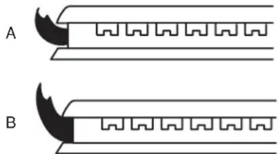
Adjust the height of top burner flames. The cooktop "low" burner flame should be a steady blue flame approximately 14 (6 mm) high. LP gas flames have a slightly yellow tip.
natural_image
Diagram showing two types of mechanical or structural components labeled A and B, with no visible text or symbols.A. Low flame
B. High flame
A. Low flame B. High flame
To Adjust Standard Burner:
The flame can be adjusted using the adjustment screw in the center of the valve stem. The valve stem is located directly underneath the control knob.
If the "Low" Flame Needs to be Adjusted:
-
Light one burner and turn to lowest setting.
-
Remove the control knob.
Hold the knob stem with a pair of pliers. Use a small flat-blade screwdriver to turn the screw located in the center of the control knob stem until the flame is the proper size. Turning the screw clockwise will increase the flame size, and turning the screw counterclockwise will decrease the flame size.
A. Control knob stem
B. Screwdriver
C. Pliers
A. Control knob stem
B. Screwdriver
C. Pliers
- Replace the control knob.
- Test the flame by turning the control from the low position to the high position, checking the flame at each setting.
- Repeat the previous steps for each burner.
To Adjust Double Burner (On Some Models):
-
Light burner and turn to lowest setting where both inner and outer burners are lit.
-
Remove the control knob.
Hold the knob stem with a pair of pliers. Use a small flat-blade screwdriver to turn the screw located in the center of the control knob stem until the flame is the proper size. Turning the screw clockwise will increase the flame size, and turning the screw counterclockwise will decrease the flame size.
A. Control knob stem
B. Screwdriver
C. Pliers
A. Control knob stem
B. Screwdriver
C. Pliers
- Replace the control knob.
- Test the flame by turning the control from the low position to the high position, checking the flame at each setting.
REPLACING AIR FILTER
The Duct Free Filter System is designed to require minimal attention between filter changes. The filter is designed to last for 6 months of average usage.
The housing can be cleaned with a paper towel and household cleaners or with a cloth and warm soapy water. No special cleaners are required.
IMPORTANT: Before cleaning and replacing the filter, make sure all controls are off and the oven and cooktop are cool.
Items you Will Need:
■ New Filter (PN# W10748931)
Changing the Filter:
- Remove Front Lower Access Panel.
natural_image
Technical diagram of a mechanical assembly with directional arrows and a magnified inset showing internal components (no text or symbols)- Unlatch and remove the Enclosure Front.
natural_image
Technical diagram of a mechanical device with directional arrows indicating motion or force (no text or symbols present)- Remove the Air Filter by gripping the two tabs at the top of the filter.
-
Thoroughly clean and dry the filter housing. You can clean the housing with a paper towel and household cleaners or with a cloth and warm soapy water. No special cleaners are required.
-
Install Air Filter into the housing and then rotate it to its final position.
NOTE: Confirm the Air Flow indicator, marked on the filter, points towards the front of the range.
flowchart
graph TD
    A["1"] --> B["2"]
    B --> C["3"]
    style A fill:#f9f,stroke:#333
    style B fill:#ccf,stroke:#333
    style C fill:#cfc,stroke:#333
Side View of Assembled Filter Housing
- Install the Enclosure Front by slightly tilting it towards you, placing in the housing, and rotating it up into the final position.
natural_image
Technical line drawing of a mechanical component with motion indicators (no text or symbols)Side View of Assembled Filter Housing
- Latch the Enclosure Front to the housing by positioning the front clasps in the slots on the top of the housing; then, push down on the clasp handles.
natural_image
Technical line drawing of a mechanical component with an inset showing a detail (no text or symbols)- Replace the Front Lower Access Panel by aligning the studs with the keyhole slots on the range. Press the access panel forward into the slots and push downward to engage the studs.
SÉCURITÉ DE LA CUISINIÈRE
natural_image
Silhouette of a person pushing a large block, no text or symbols presentAVERTISSEMENT
natural_image
Isometric line drawing of a rectangular device with two side slats and a small protrusion on the right side (no text or symbols)natural_image
Technical line drawing of a mechanical assembly with no visible text or symbolsnatural_image
Isometric line drawing of a rectangular metal frame with mounting holes (no text or symbols)■ Devant du boîtier
natural_image
Technical line drawing of a rectangular mechanical component with two side clips (no text or symbols)natural_image
Isometric line drawing of a three-legged support bracket (no text or symbols)natural_image
Illustration of a plastic bin with recycling symbol, showing a blank panel and a recycling bin with recycling symbols (no text or labels)Pièces nécessaires
Canadian Standards Association
178 Rexdale Blvd.
Toronto, ON M9W 1R3 CANADA
natural_image
Silhouette of a person pushing a large block on a horizontal line (no text or symbols)natural_image
Silhouette of a person pushing a large block on a horizontal line (no text or symbols)natural_image
Three technical line drawings of metal bracket assemblies with mounting holes (no text or symbols)natural_image
Technical line drawing of a mechanical bracket or mounting bracket (no text or symbols)natural_image
Technical line drawing of a mechanical component with a fan-like structure and internal channels, showing no text or symbols.natural_image
Pure architectural line drawing of two symmetrical structures with a central horizontal dimension labeled 'A' (no text or symbols beyond the label)A. Center line
natural_image
Technical line drawing of a mechanical assembly with an inset showing a close-up of a component (no text or symbols present)natural_image
Two technical line drawings of a device interior with ventilation grilles and a central component (no text or symbols)natural_image
Line drawing of a hand installing or adjusting a wall-mounted panel or fixture (no text or symbols present)natural_image
Pure technical line drawing of a structural frame with no text, numbers, or symbolsnatural_image
Technical line drawing of a mechanical fan or vent assembly with internal components and structural details (no text or symbols)natural_image
Technical line drawing of a heating fan with cooling fins and a circular vent (no text or symbols)natural_image
Diagram of a heat exchanger or cooling unit with cooling fins and a circular fan (no text or symbols)natural_image
Technical line drawing of a mechanical component with curved and flat surfaces, no text or symbols presentnatural_image
Line drawing of a desk setup with books, a fan-shaped object, and a chair (no text or symbols)natural_image
Technical line drawing of a mechanical assembly or structural component (no text or symbols)natural_image
Diagram of a mechanical device with a magnified inset showing internal components (no text or symbols)natural_image
Technical line drawing of a mechanical component with a textured circular feature and rectangular base (no text or symbols)Position finale
natural_image
Technical line drawing of a mechanical component with a labeled 'Vis' feature (no other text or symbols)natural_image
Technical line drawing of an electrical connector with cable and screw base (no text or symbols)natural_image
Pure electrical connector diagram showing two terminal blocks connected by wires (no text or symbols)natural_image
Technical line drawing of an electrical enclosure with wiring and connectors (no text or symbols)natural_image
Technical line drawing of a mechanical assembly with an inset showing a close-up of a component (no text or symbols present)natural_image
Technical line drawing of a mechanical assembly with bolts and a cylindrical component (no text or symbols)natural_image
Technical line drawing of a mechanical device with motion indicators (no text or symbols)natural_image
Technical line drawing of a mechanical bracket assembly with an inset magnified detail (no text or symbols)natural_image
Technical line drawing of a structural frame with an inset showing two circular components labeled 1 and 2 (no text or symbols present)natural_image
Four circular mechanical components labeled A, B, C, D, with no visible text or symbols on the parts themselves.A. Petit
B. Grand
C. Moyen
D. Grand
A. Incorrect
B. Correct
natural_image
Silhouette of a person pushing a large block on a horizontal line (no text or symbols)natural_image
Pure technical diagram of a mechanical or electrical component with no visible text, numbers, or symbolsA. Détendeur
natural_image
Silhouette of a person pushing a large block on a horizontal line (no text or symbols)natural_image
Technical line drawing of a mechanical component with labeled point A (no text or symbols present)A. Détendeur
natural_image
Two identical diagrams of a mechanical component with serrated edges, labeled A and B (no text or symbols on the components themselves)natural_image
Technical line drawing of a mechanical device with directional arrows indicating motion (no text or symbols)natural_image
Technical line drawing of a mechanical assembly with a magnified inset showing a component detail (no text or symbols)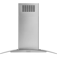

- DUCTLESS INSTALLATION INSTRUCTIONS SLIDE-IN DOWNDRAFT RANGES
- INSTRUCTIONS D'INSTALLATION SANS CONDUIT DES CUISINIÈRES À ÉVACUATION PAR LE BAS ENCASTRABLES
- Table of Contents/Table des matières
- Your safety and the safety of others are very important.
- DANGER
- WARNING
- INSTALLATION REQUIREMENTS
- Tools and Parts
- Tools Needed
- For LP/Natural Gas Conversions
- Parts Supplied
- Parts Needed
- Optional Parts
- Side Trim Kits:
- ■ Backsplash Kits:
- Location Requirements
- Mobile Home – Additional Installation Requirements
- Mobile Home Installations Require:
- Product Dimensions
- Cabinet Dimensions
- Electrical Requirements – U.S.A. Only
- Electrical Connection
- Electrical Requirements – Canada Only
- Range Rating\*
- 120/240 Volts 120/208 Volts Amps Temp Rating
- Gas Supply Requirements
- Type of Gas
- Natural Gas:
- LP Gas Conversion:
- Gas Supply Line
- Flexible Metal Appliance Connector:
- Gas Pressure Regulator
- LP Gas:
- Burner Input Requirements
- Gas Supply Pressure Testing
- Line Pressure Testing Above 12 psi Gauge (14" WCP)
- Line Pressure Testing at 12 psi Gauge (14" WCP) or Lower
- INSTALLATION INSTRUCTIONS
- Adjust Leveling Legs
- Install Anti-Tip Bracket
- Install Recirculation Blower Assembly
- Items Needed:
- Assemble Recirculation Housing
- Position the Blower
- Secure the Blower
- Install Blower
- Install Blower Cover
- Make Utility Connections
- Make Gas Connection
- Explosion Hazard
- Typical Flexible Connection
- Complete Connection
- Connect Blower Assembly to Range
- Connect Blower Electrical Parts
- Complete Filter Assembly
- You Will Need
- Make Electrical Connection
- Verify Anti-Tip Bracket Is Installed and Engaged
- Oven Door
- To Remove:
- To Replace:
- Complete Installation
- If Range Does Not Operate, Check the Following:
- Initial Lighting and Gas Flame Adjustments
- Standard Surface Burners
- If Burners Do Not Light Properly:
- If You Need Assistance or Service:
- Electronic Ignition System
- GAS CONVERSIONS
- LP Gas Conversion
- Tip Over Hazard
- To Convert Gas Pressure Regulator (Natural Gas to LP Gas)
- To Convert Surface Burners (Natural Gas to LP Gas)
- Complete Installation (Natural Gas to LP Gas)
- Natural Gas Conversion
- To Convert Gas Pressure Regulator (LP Gas to Natural Gas)
- To Convert Surface Burners (LP Gas to Natural Gas)
- Complete Installation (LP Gas to Natural Gas)
- Adjust Flame Height
- Adjust Surface Burner Flame
- To Adjust Standard Burner:
- If the "Low" Flame Needs to be Adjusted:
- To Adjust Double Burner (On Some Models):
- REPLACING AIR FILTER
- Items you Will Need:
- Changing the Filter:
- SÉCURITÉ DE LA CUISINIÈRE
- AVERTISSEMENT
- Pièces nécessaires
Brand : JENN-AIR
Model : W10748976
Category : Range hood