
SuperFreeze SF2500 - Freezer RIDGID - Free user manual and instructions
Find the device manual for free SuperFreeze SF2500 RIDGID in PDF.
| Product Type | Pipe freezing unit for creating ice plugs in pipelines |
| Brand | Ridgid |
| Model | SuperFreeze SF2500 |
| Dimensions (L x W x H) | 633 x 279 x 368 mm |
| Weight | 31 kg |
| Power Supply | Single-phase 230V / 50 Hz |
| Motor Power | 505 W |
| Fan Power | 2 x 17 W |
| Refrigerant | R-507 |
| Hose Length | 2.60 m |
| Compatible Copper Pipe Diameter | 12 to 54 mm (DN 12 to 42 mm) |
| Compatible Steel Pipe Diameter | 15 to 25 mm (DN 15 to 32 mm) |
| Standard Accessories | 2 freezing heads, Velcro straps, clamp, freezing gel, sprayer, instruction manual |
| Main Functions | Creation of ice plugs for pipe interventions without draining |
| Max. Ambient Temperature (operation) | 43 °C for pipes ≤ 1" (25 mm), 32 °C for 1 1/4" to 1 1/2", 27 °C for 2" or more |
| Max. Water Temperature | 43 °C (for small diameters) |
| Maintenance and Cleaning | Clean the heads and fan grilles with a soft cloth; dry after use |
| Safety Instructions | Use a grounded outlet; wear gloves and safety glasses; do not touch frosted heads |
| Spare Parts Available | Pads, tip adapters, freezing gel, Velcro straps, clamp |
| Warranty | Lifetime warranty (conditions see manual) |
| Repairability | Reserved for authorized RIDGID repairers; contains refrigerant gas |
| Usage | Professional, for plumbers and heating engineers |
Frequently Asked Questions - SuperFreeze SF2500 RIDGID
User questions about SuperFreeze SF2500 RIDGID
0 question about this device. Answer the ones you know or ask your own.
Ask a new question about this device
Download the instructions for your Freezer in PDF format for free! Find your manual SuperFreeze SF2500 - RIDGID and take your electronic device back in hand. On this page are published all the documents necessary for the use of your device. SuperFreeze SF2500 by RIDGID.
USER MANUAL SuperFreeze SF2500 RIDGID
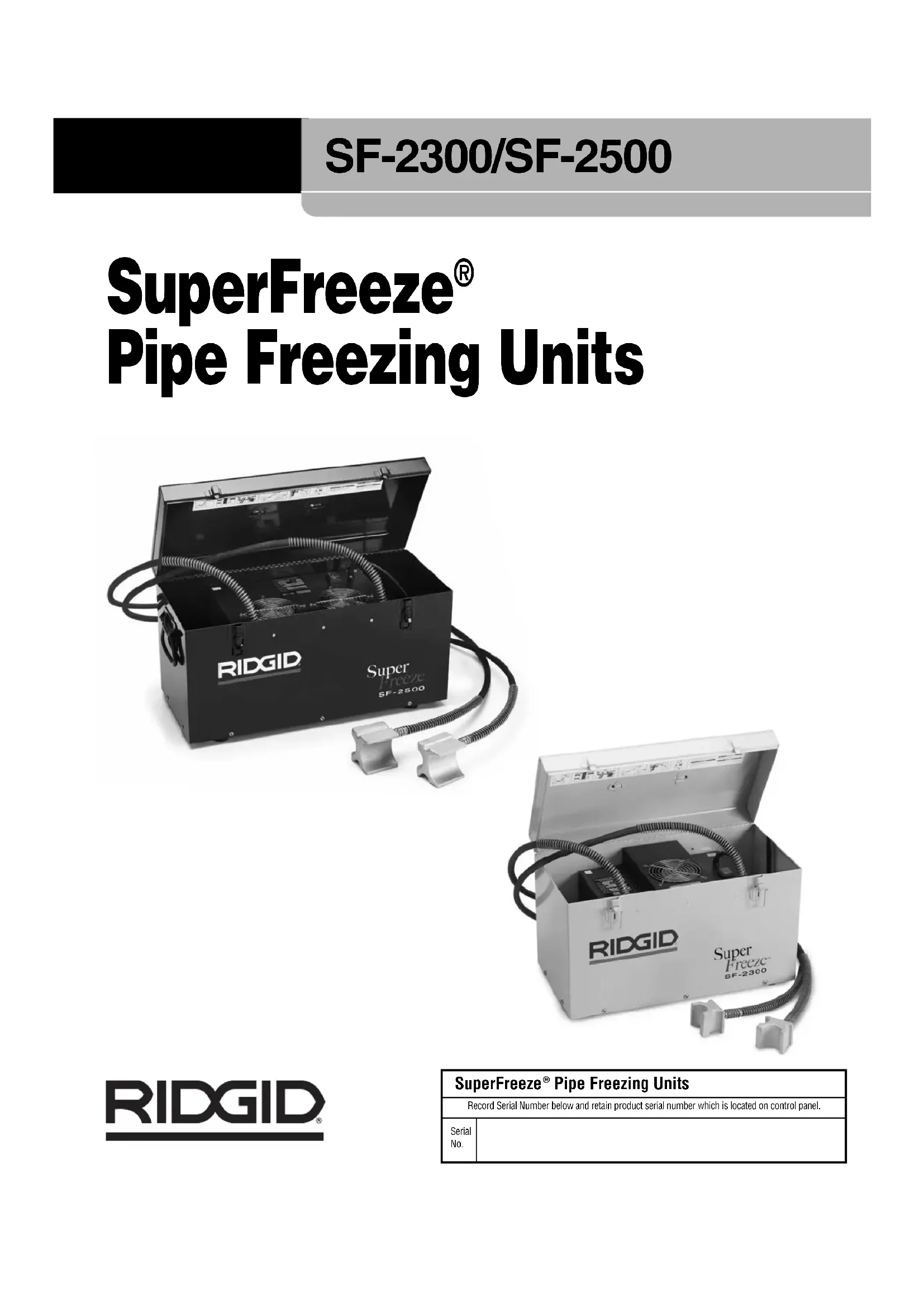
SuperFreeze® Pipe Freezing Units
natural_image
Ridgid Super Freeze SF-2500 device with coiled tubing and two connectors (no visible text or symbols on main body)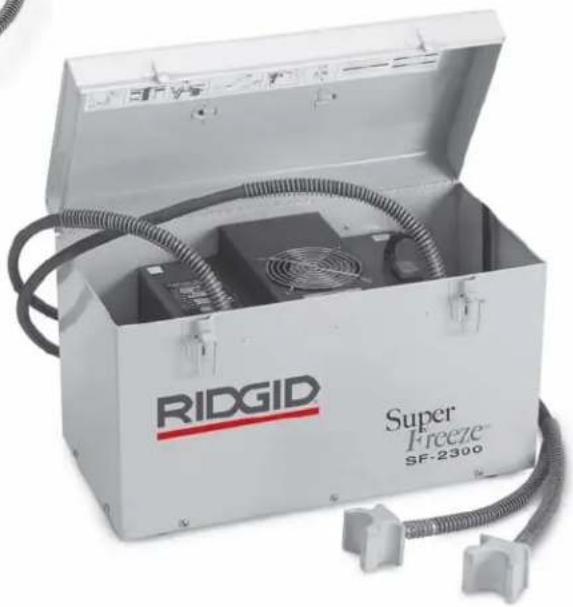
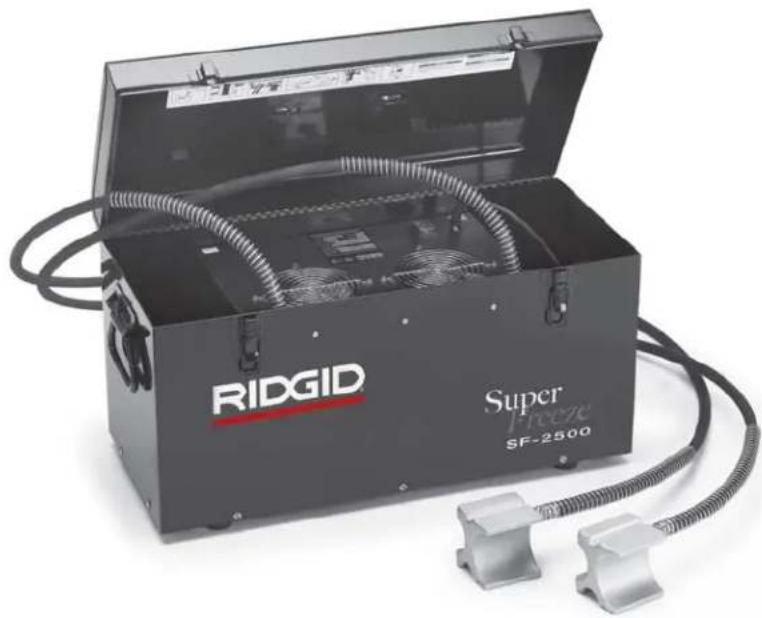
natural_image
Ridgid Super Freeze SF-2300 portable electronic device with coiled cable and fan (no visible text or symbols on main body)! WARNING!
Read this Operator's Manual carefully before using this tool. Failure to understand and follow the contents of this manual may result in extensive property damage and/or serious personal injury.
- Français – 13
Recording Form for Machine Serial Number....1
Safety Symbols....2
General Safety Rules
Work Area Safety 2
Electrical Safety 2
Personal Safety 2
Power Tool Use and Care ....3
Service....3
Pipe Freezing Unit Safety Warnings....3
Description, Specifications and Standard Equipment
Description....3
Specifications....4
Standard Equipment 4
Icons 4
Pre-Operation Inspection ....5
Machine and Work Area Set-Up ....5
Capacities for Copper Tube & Steel Pipe 6
Operating Instructions....8
Freezing Times 9
Cleaning 9
Accessories 10
Machine Storage....10
Service and Repair....10
Disposal 10
Troubleshooting....11
Lifetime Warranty ....Back Cover
*Original Instructions - English
SuperFreeze® Pipe Freezing Units
natural_image
Ridgid Super Freeze SF-2500 device with coiled tubing and two metallic connectors (no visible text or symbols on main body)
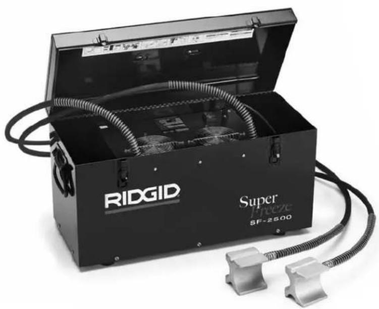
natural_image
Open RIDGID Super Freeze SF-2300 device with coiled tubing and fan (no visible text or symbols on main body)RIDGID®
| SuperFreeze® Pipe Freezing Units | |
| Record Serial Number below and retain product serial number which is located on control panel. | |
| Serial No. | |
Safety Symbols
In this operator's manual and on the product, safety symbols and signal words are used to communicate important safety information. This section is provided to improve understanding of these signal words and symbols.

This is the safety alert symbol. It is used to alert you to potential personal injury hazards. Obey all safety messages that follow this symbol to avoid possible injury or death.

DANGER
DANGER indicates a hazardous situation which, if not avoided, will result in death or serious injury.

WARNING
WARNING indicates a hazardous situation which, if not avoided, could result in death or serious injury.

CAUTION
CAUTION indicates a hazardous situation which, if not avoided, could result in minor or moderate injury.
NOTICE
NOTICE indicates information that relates to the protection of property.

This symbol means read the operator's manual carefully before using the equipment. The operator's manual contains important information on the safe and proper operation of the equipment.

This symbol means always wear safety glasses with side shields or goggles when handling or using this equipment to reduce the risk of eye injury.

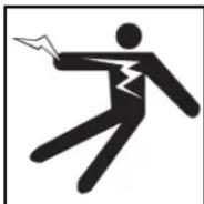
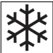
This symbol indicates the risk of frostbite from a cold surface.

This symbol indicates the risk of electrical shock.
General Safety Rules
WARNING
Read all safety warnings and all instructions. Failure to follow the warnings and instructions may result in electric shock, fire and/or serious injury.
SAVE ALL WARNINGS AND INSTRUCTIONS FOR FUTURE REFERENCE!
Work Area Safety
- Keep your work area clean and well lit. Cluttered or dark areas invite accidents.
- Do not operate tools in explosive atmospheres, such as in the presence of flam mable liquids, gases, or dust. Tools create sparks which may ignite the dust or fumes.
- Keep children and by-standers away while operating a tool. Distractions can cause you to lose control.
Electrical Safety
- Grounded tools must be plugged into an outlet properly installed and grounded in accordance with all codes and ordinances. Never remove the grounding prong or modify the plug in any way. Do not use any adapter plugs. Check with a qualified electrician if you are in doubt as to whether the outlet is properly grounded. If the tool should electrically malfunction or break down, grounding provides a low resistance path to carry electricity away from the user.
- Avoid body contact with grounded surfaces such as pipes, radiators, ranges and refrigerators. There is an increased risk of electrical shock if your body is grounded.
- Do not expose the equipment to rain or wet conditions. Water entering a tool will increase the risk of electrical shock.
- Do not abuse the cord. Never use the cord for carrying, pulling or unplugging the tool. Keep cord away from heat, oil, sharp edges or moving parts. Replace damaged cords immediately. Damaged or entangled cords increase the risk of electric shock.
- When operating a tool outside, use an outdoor extension cord marked "W-A" or "W". These cords are rated for outdoor use and reduce the risk of electric shock.
Personal Safety
- Stay alert, watch what you are doing and use common sense when operating a tool. Do not use a tool while you are tired or under the influence of drugs, alcohol, or medication. A moment of inattention while operating tools may result in serious personal injury.
- Use personal protective equipment. Always wear eye protection. Protective equipment such as dust mask, non-skid safety shoes, hard hat, or hearing protection used for appropriate conditions will reduce personal injuries.
- Do not overreach. Keep proper footing and balance at all times. This enables better control of the power tool in unexpected situations.
Tool Use and Care
- Do not force the tool. Use the correct tool for your application. The correct tool will do the job better and safer at the rate for which it is designed.
- Do not use tool if the switch does not turn it ON and OFF. Any tool that cannot be controlled with the switch is dangerous and must be repaired.
- Disconnect the plug from the power source before making any adjustments, changing accessories, or storing the tool. Such preventive safety measures reduce the risk of starting the tool accidentally.
- Store idle tools out of the reach of children and other untrained persons. Tools are dangerous in the hands of untrained users.
- Maintain the tools. Check for misalignment or binding of moving parts, breakage of parts and any other condition that may affect the tool's operation. If damaged, have the tool re paired before use. Many accidents are caused by poorly maintained tools.
- Use only accessories that are recommended by the manufacturer for your model. Accessories that may be suitable for one tool, may become hazardous when used on another tool.
Service
- Have your tool serviced by a qualified repair person using only identical replacement parts. This will ensure that the safety of the tool is maintained.
Pipe Freezing Unit Safety Warnings
WARNING
This section contains important safety information that is specific to this tool.
Read these precautions carefully before using the SuperFreeze units to reduce the risk of electrical shock or other serious injury.
SAVE THESE INSTRUCTIONS!
The SuperFreeze ® units include space in the unit to keep this manual with machine for use by the operator.
- This tool is used to freeze a water plug inside cop per, steel or other thermally conductive metallic tubes or pipes. Do not use on plastic pipe or
tube. Follow instructions on proper use. Other uses may increase the risk of injury.
- Do not touch the freeze heads while frosted. Touching the freeze heads while frosted can cause frostbite. Wear gloves if handling during use.
- Before opening piping system, test to confirm that the ice plugs are fully formed and stable. Opening the piping system before a complete plug is frozen or allowing the plug to thaw while the system is open could cause burns, electric shock or other serious injury or result in flooding or other property damage.
- Do not twist, kink or pull hoses. Do not open refrigerant piping. This can lead to refrigerant leaks and cause frostbite, asphyxiation and other serious injury. If a leak occurs, leave the area until the refrigerant dissipates.
The EC Declaration of Conformity (890-011-320.10) will accompany this manual as a separate booklet when required.
If you have any question concerning this RIDGID® product:
- Contact your local RIDGID distributor.
- Visit www.RIDGID.com or www.RIDGID.eu to find your local RIDGID contact point.
- Contact Ridge Tool Technical Service Department at rttechservices@emerson.com, or in the U.S. and Canada call (800) 519-3456.
Description, Specifications and Standard Equipment
Description
The RIDGID® SuperFreeze® Pipe Freezing Units are used to freeze plugs in water piping systems to allow maintenance without shutting down or draining the system. The units are self-contained refrigeration units that circulate refrigerant to the aluminum freeze heads. The freeze heads, attached to the piping system, can freeze a plug in metallic tubing or pipes. Once the work is complete, the SuperFreeze unit is turned OFF and the ice plugs melt, returning the system to operation.
The SuperFreeze units do not use CO2 or Nitrogen, and do not require the release of refrigerants. They use specially designed compressors with overload protection. The SF-2500 also includes quick restart capabilities. The freeze head hoses are leak free flexible rubber. The units are enclosed in a portable carry case.
Specifications
| Parameter\Model SF-2500, 115V SF-2500, 230V SF-2300, 230V | |||
| Capacity: Copper Tube | 12 to 212 inch CTS 12 to 54 mm DN* 12 to 42 mm DN | ||
| Capacity: Steel Pipe | 12 to 1 inch*(15 to 25 mm) (15 to 50 mm) | 12 to 2 inch(15 to 32 mm) | 12 to 114 inch* |
| Hose Length 8.5 ft (2.6 m) 8.5 ft (2.6 m) 6.5 ft (2 m) | |||
| Hose Span 17 ft (5.2 m) 17 ft (5.2 m) 13 ft (4 m) | |||
| Refrigerant R-507 R-507 R-507 | |||
| Compressor Type Rotary, Hermetic, Low Back Pressure Reciprocating | |||
| Motor Power 627 W | 505 W | 296 W | |
| Fan Motor Power | 2 × 18 W | 2 × 17 W | 17 W |
| Electric Supply | 115 V, 1 Ph, 60 Hz | 230 V, 1 ph, 50 Hz | 230 V, 1 ph, 50 Hz |
| Dimension | 2412 × 11 × 1412 inch(633 x 279 x 368) | 21 × 1012 × 13 inch(533 x 267 x 330) | |
| Weight | 69 lb (31 kg) | 58 (26 kg) | |
* The freeze head cavities on these units are specifically sized for copper tube sizes. They may be used on steel pipe sizes with adherence to the instructions. * The freeze head cavities on these units are specifically sized for steel pipe sizes. They may be used on copper tube sizes with adherence to the instructions.
Standard Equipment
All SuperFreeze pipe freezing units come with the following:
- Two Velcro Straps with D-Ring
- Quick Grip Clamp
- Freeze Gel
- Water Spray Bottle
- Operator's Manual
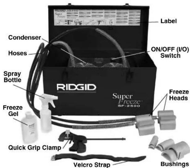
Figure 1 – SF-2500 SuperFreeze Unit
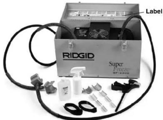
Figure 2 – SF-2300 SuperFreeze Unit
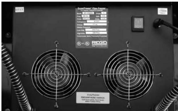
Figure 3 – Unit Serial Number
The machine serial number is located on the control panel. An additional decal is supplied that indicates the month and year of manufacture. (05 = Month, 13 = Year)
Icons


NOTICE This product is used to freeze ice plugs in water piping systems. The ability to freeze plugs is dependant on a wide variety of factors as discussed in this manual. Depending upon the exact set of circumstances, this product may not work in all cases.
Pre-Operation Inspection
WARNING

Before each use, inspect your pipe freezing unit and correct any problems to reduce the risk of serious injury from electrical shock and other causes and prevent unit damage.
- Make sure that the pipe freezing unit is unplugged and the ON/OFF switch is in the OFF position.
- Clean any oil, grease or dirt from all equipment and controls. This aids inspection and control of the unit.
-
Inspect the pipe freezing units for the following:
-
Inspect the cord and plug for damage or modification.
- Proper assembly, maintenance and completeness.
- Any broken, worn, missing, misaligned or binding parts.
- Presence and readability of the warning label. (See Figures 1 and 2.)
- Any other condition, which may prevent safe and normal operation.
If any problems are found, do not use the pipe freezing unit until the problems have been repaired.
- Check the hoses to the freeze heads for cracks, kinks, breaks or other issues. The hoses can be coiled and flexed when not frosted. Care must be taken not to twist or kink hoses. This prevents hose damage.
- Inspect the fan grille and louvers into the condenser housing to make sure that nothing is blocking the airflow. Lack of airflow through the unit can cause performance issues or damage the unit.
- With dry hands, plug cord into properly grounded outlet, Move the switch to ON position. Confirm that the compressor motor starts and that the fan runs. Move the switch to OFF position and unplug the unit.
Machine and Work Area Set-Up
WARNING

Set up the pipe freezing units and work area according to these procedures to reduce the risk of burns, electrical shock and other injuries and prevent machine damage.
-
Check work area for:
-
Adequate lighting.
- Flammable liquids, vapors or dust that may ignite. If present, do not work in area until sources have been identified and corrected. The Pipe Freezing Units are not explosion proof and can cause sparks.
- Clear, level, stable, dry location for all equipment and operator.
- Properly grounded electrical outlet of the correct voltage. A three-prong or GFCI outlet may not be properly grounded. If in doubt, have outlet inspected by a licensed electrician.
- Clear path to electrical outlet that does not contain any potential sources of damage for the power cord.
-
Clear path for access to the work area.
-
Inspect the system and determine if the Pipe Freezing Unit will work.
-
Determine the system fluid – the unit will only work on systems containing water. Know what additives are in the water. Additives can change liquid freeze temperature and make freezing difficult or impossible.
- Determine the system material and size – the unit will only work on metallic piping systems. For pipe and tube material and size see Specifications.
- Determine the system water temperature and air temperature in the area of the desired plug. If temperatures exceed
up to 1" (25 mm) sizes - 110°F (43°C)
11/4 (32 mm) and 11/2 (42 mm) sizes - 90°F (32°C) 2 (54 mm) and larger sizes - 80°F (27°C)
The water/air must be cooled to below these temperatures for the SuperFreeze unit to be used.
- Determine if there is flow in the system – the pipe freezing unit will not work on flowing water. If there is flow in the section of pipe to be frozen, the flow needs to be stopped by shutting a valve, turning OFF a circulating pump, or other appropriate means.
- Determine if the piping is filled with water. A plug cannot be frozen into partly filled pipes.
- Determine where the piping system needs to broken for the work that needs to be done.
- Locate piping system shut-off valves or determine other methods to shut off system fluid flow to be used in case of emergency.
3. Determine location for freeze plug(s).
- The location must allow access for at least one freeze head. If only a single plug is required, it is preferred that there be enough space for both freeze heads. Freeze heads should not contact more than one pipe.
- If the system will be soldered, brazed, welded, or other heat adding processes performed, the freeze plug(s) must be located as far away from the repair as possible. Excess heat can prematurely thaw the ice plug and allow water to flow while the system is open. The freeze plugs should be a minimum of one foot (0.3 m) away from the heat for each inch (25 mm) of diameter for steel pipe or tube. For all other materials, the plug should be at least three feet (0.9 m) away for each inch of pipe or tube diameter.
- Ice plugs must be more than one foot (0.3 m) away from end caps, elbows, closed valves, other ice plugs or similar obstructions. Placing an ice plug closer can cause splitting of the pipe or tube.
- Do not place ice plugs closer than 5 feet (1.5 m) from a circulating hot water (water hotter than ambient air but cooler than 100°F (38°C)) main for pipe sizes 1" (25 mm) and smaller or closer than 8 feet (2.4 m) from a circulating hot water main 1 1/4 " (30 mm) or larger. Plugs placed closer to a circu-
lating hot water main can prevent plug formation or can cause plug thawing.
- Prepare the freeze plug locations. Remove all insulation and coatings from the pipe down to bare metal. If needed, remove any corrosion with a wire brush. Coatings and corrosion insulate the pipe and can slow or prevent the freezing process.
- Place the unit so that freeze heads can reach desired plug points. Locate SuperFreeze on a solid, level surface, in an upright position. If the unit is not upright and level, it can cause damage to the compressor. Make sure the air inlet/outlet to condenser are not blocked. Blocked condenser openings will slow or prevent the freezing process. Be sure to locate the pipe freezing unit away from where the repair will occur and not under the freeze heads. This will help prevent the entry of water into the freezing unit and help prevent electrical shock.
- Uncoil the hoses to the freeze heads. Use care not to twist or kink the hoses, this can damage the hose and prevent proper operation.
- Choose the appropriate freeze head cavity for the size of pipe or tube to be frozen. The capacities for copper tube and steel pipe are listed in the chart that follows. Adapter bushings are required in some applications. If using on pipe or tube other than listed sizes, the pipe/tube diameter cannot be smaller than the freeze head/bushing diameter -1/8" (3.2 mm).
- Apply freeze gel to the freeze head cavity. If using end adapter or bushings, apply freeze gel between the freeze head and the adapter and to the adapter surface that contacts the pipe. The freeze gel improves
Capacities for Copper Tube and Steel Pipe
| Model Freeze Head Copper Tube (CTS) Steel Pipe | # | Cavity | Req'd Bushing | ||
| SF-2500,115V Domestic (68967)and 230V DomesticExport (68962) | 2 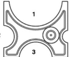 4 4 | 1/2 " | — | 4 | |
| 3/4 " | 1/2 " 2 Cat. | #69712 | |||
| 1" | 3/4 " | 2 | |||
| 11/4 " | 1" 3 | Cat.#70652 | |||
| 11/2 " | — | 3 | |||
| 2" — 1 Cat. | #69717 | ||||
| 21/2 " | — | 1 | |||
* See Specifications
| Model | Freeze Head | Copper Tube (DN)* | Steel Pipe | Cavity | End Adapter | |
| SF-2500, 230V European Model (68832) | 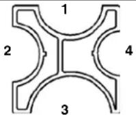 | 22 mm | 1/2'' (15 mm) | — | Cat. #68837 | |
| 28 mm | 3/4'' (20 mm) | — | Cat. #72427 | |||
| 35 mm | 1" (25 mm) | 4 | — | |||
| 42 mm | 11/4'' (32 mm) | 2 | — | |||
| 11/2'' (40 mm) | 1 | — | ||||
| 2" (50 mm) | 3 | — | ||||
* See Specifications
| Model Freeze Head Copper Tube (DN) | # | Steel Pipe Cavity Req'd Bushing | ||
| SF-2300, 230V European Model (41078) | 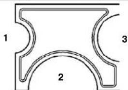 | 12 mm — 1 4238 | ||
| 15 mm — 1 42353 | ||||
| 18 mm — 1 — | ||||
| 22 mm | 1/2 " (15 mm) 3 42843 | |||
| 28 mm | 3/4 " (20 mm) 3 — | |||
| 35 mm 1" (25 mm) 2 42833 | ||||
| 42 mm 1 | 1/4 " (32 mm) 2 — | |||
* See Specifications
the thermal conductivity between the freeze head and the pipe and decreases the time required to freeze a plug. If no freeze gel is available, use the spray bottle to spray water generously before and during the pipe freezing process.
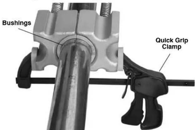
Figure 4 – Attaching Freeze Heads Using Quick Grip Clamp
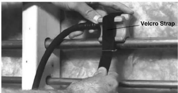
Figure 5 – Applying Freeze Head with Velcro Strap
- Attach the freeze heads to the pipe.
- Single freeze plug applications – In single freeze plug applications, both freeze heads should be applied opposite each other to form the plug. This will decrease the time required to freeze the plug. Use the Quick Grip clamp (Figure 4) or Velcro Strap (Figure 5) to secure the freeze heads to the pipe. If using the Quick Grip clamp do not over tighten the clamp and deform the pipe.
Forming a single freeze plug with freeze heads positioned opposite to each other and using freeze gel and quick grip clamp is the preferred method for use on more difficult applications (higher temperatures, larger pipe sizes, etc.). If two freeze plugs are required in a difficult application, it may be necessary to use two pipe freezing units, one for each plug.
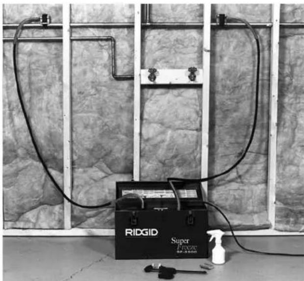
- Two freeze plug applications – When two separate freeze plugs are required to isolate a section of the system, one freeze head is attached at each point (Figure 6). Tightly secure the freeze heads to the pipe with either Quick Grip clamp or Velcro straps. If using the Quick Grip clamp do not over tighten the clamp and deform the pipe.
natural_image
Ridgid Super Precision 80-200mm power supply kit with tubing and spray bottle, installed in a concrete wall (no text or symbols visible on main subject)Figure 6 – Two Freeze Plug Application
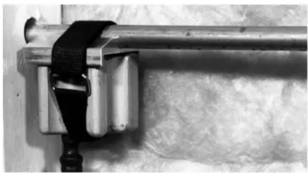
- If the standard freeze head cannot be used, adapters are available. Freeze gel (if being used) is applied to the back of the adapter and to the surface that contacts the tube. Tightly secure the freeze heads to the tube with either the Quick Grip clamp or the Velcro straps. If using the Quick Grip clamp do not over tighten the clamp and deform the tube. See Figure 7.
natural_image
Close-up of a metallic pipe with attached clamping bracket and textured wall (no text or symbols visible)Figure 7 – Freeze Head with End Adapter Attached with Velcro Strap
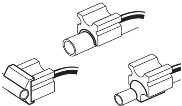
natural_image
Three technical line drawings of electrical connectors with wires, no text or symbols presentFigure 8 – Freeze Heads with Various Adapters
-
Run cord along previously identified clear path. With dry hands, plug the SuperFreeze into the previously identified properly grounded outlet. If the power cord is not long enough, use an extension cord that
-
Is in good condition.
- Has a three prong plug similar to that supplied on the Pipe Freezing Unit.
- Is rated for outdoor use and contains a W or W-A in the cord designation (i.e. SOW), or complies with H05VV-F, H05RN-F types or IEC type design (60227 IEC 53, 60245 IEC 57).
- Has sufficient wire size (16 AWG (1.5 mm 2 ) for 50' (15.2 m) or less, 14 AWG (2.5 mm 2 ) for 50' – 100' (15.2 m – 30.5 m) long). Undersized wires can overheat, melting the insulation or causing a fire or other damage.
Operating Instructions
WARNING

Before opening system, test to confirm that the ice plugs are fully formed and stable. Opening the piping system before a complete plug is frozen or allowing the plug to thaw while the system is open could cause burns, electric shock or other serious injury or result in flooding or other property damage. Make sure the machine is properly set up and do not allow the Pipe Freezing Unit to shut OFF during use.
The freeze heads and hoses get extremely cold and can cause frostbite if touched during operation. Wear gloves if handling during use.
Always wear eye protection to protect your eyes from dirt and other foreign objects. Always wear appropriate protective equipment for the piping contents.
Follow operating instructions to reduce the risk of injury from burns, frostbite, electrical shock and other causes.
- Make sure that machine and work area is properly set up and that the work area is free of bystanders and other distractions.
- Turn the machine ON.
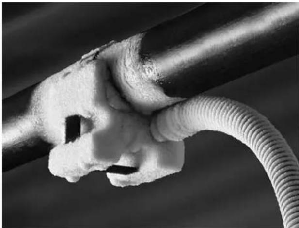
- Allow the machine to run for 2-3 minutes. Freeze heads should start to frost. Use spray bottle to spray water between freeze heads and pipe. The water will freeze and fill any gaps between the freeze head, pipe and any adapters used. This improves thermal conductivity and will improve freeze times, while gaps between the freeze head and pipe will prevent freeze plug formation. Make sure that any dripping water does not cause a hazard. If freeze gel was used, then water spray may not be necessary.
If the freeze heads do not become cold and covered with ice and frost after approximately 7 minutes, turn the unit OFF for 3 minutes and restart. If the freeze heads still do not become cold, see the "Troubleshooting" section.
- Once the freeze heads are frozen to the pipe, allow the ice plug to form. If the ambient temperature is high, but not above 100irc F ( 38irc C), the freeze heads can be wrapped with pipe insulation or other insulation to improve freeze times.
Do not leave the unit unattended. Pipes can freeze and split during the freezing process and monitoring can minimize the hazard and damage. If for some reason the power to the freezing unit is interrupted, turn the ON/OFF switch to OFF and do not restart for at least 30 seconds to prevent compressor damage.
natural_image
Close-up of a hand holding a coiled cable with a white foam-like substance (no text or symbols visible)Figure 9 – Freeze Head Frozen to Pipe
Time to freeze a fully formed ice plug depends on a variety of factors, including water temperature, ambient temperature, distance from heat sources, pipe size and wall thickness, pipe material, number of freeze heads, quality of contact between freeze heads and pipe, and other conditions. The following table of freeze times is based on water temperature being the same as ambient temperature, use on copper tube, use of freeze gel and use of two freeze heads. Freeze times for steel pipe will be longer. Freeze times for other less optimal conditions may be double those shown or greater. Freeze times are only provided as a general guide.
- Carefully test the system to make sure that the plugs are complete and there is no flow before opening the system. This can be done by opening a valve downstream of the plug and verifying that there is no flow. Another method is to use a saddle tap valve (similar to those used to install icemakers) to pierce a copper tube and check for water flow. If there is flow, close the system and continue the freezing process.
Wait at least five more minutes after confirmation that there is no water flow to proceed with opening the system for work. On high temperature applications, water temperature over 90irc F ( 32irc C) but below 100irc F ( 38irc C), wait at least 15 minutes. Do not shut OFF the freezing unit.
Freezing Times
| Nominal Copper Ambient/Water Approx. Freezing Times Tube Diameter Temperature (Minutes) | |||||
| CTS Inches | DN mm °F °C | SF-2500 SF-2300 | |||
| 12 | 15 80 2 | 70 21 6 5 | |||
| 6 8 6 | |||||
| 90 32 10 | 8 | ||||
| 34 | 22 | 70 21 8 | 6 | ||
| 80 26 10 | 8 | ||||
| 90 32 13 10 | |||||
| 1 | 28 | 70 21 10 10 | |||
| 80 26 | 13 | 12 | |||
| 90 32 16 15 | |||||
| 114 | 35 | 70 21 12 NA | |||
| 80 26 15 NA | |||||
| 90 32 19 NA | |||||
| 112 | 42 | 70 21 19 21 | |||
| 80 26 22 26 | |||||
| 90 32 28 42 | |||||
| 2 | 54 | 70 21 23 NA | |||
| 80 26 | 25 | NA | |||
| 90 32 28 NA | |||||
| 212 | 70 21 40 NA | ||||
| 80 26 51 NA | |||||
| 90 32 55 NA | |||||
- Once the ice plug has been completely formed and enough time has passed since confirmation that there is no flow in the pipe, the pipe can be opened. When opening the system, be prepared for the possibility of liquid coming out of the line and wear proper protective equipment in case a plug fails. Be sure to follow the guidelines in the set up section for distance from plug to heating of system for soldering, brazing, etc. Do not shut OFF the freezing unit while making repairs. This will help insure that the plug does not melt while the system is open.
- When the repair is complete and system is closed, shut OFF and unplug pipe freezing unit, and allow ice and frost to melt off the freeze heads and hoses.
NOTICE Do not try to remove the freeze heads from the pipe or coil the hoses until they are completely thawed. This can result in damage to the hoses and freeze heads. If freeze heads and hoses must be removed more quickly, a heat gun can be used to thaw them.
Cleaning
After each use, clean the freeze heads with a soft cloth. Clean the condenser fan grilles to remove dirt. Wipe frost/water from the fully thawed freeze heads and hoses.
Accessories
WARNING
To reduce the risk of serious injury, only use accessories specifically designed and recommended for use with the SuperFreeze Pipe Freezing Units such as those listed below. Other Accessories suitable for use with other tools may be hazardous when used with the Pipe Freezing Units.
| Catalog No. Description | |
| For SF-2500: | |
| 69712 SF-2500R | 3/4 " CTS Bushings (set of 2) |
| 70652 SF-2500R 1 | 1/4 " CTS Bushings (set of 2) |
| 69717 SF-2500R 2" | CTS Bushings (set of 2) |
| 68857 SF-2500R | 1/2 " End Adapters (set of 2) |
| 68862 SF-2500R | 3/4 " CTS End Adapters (set of 2) |
| 68837 SF-2500R 22 mm | End Adapters (set of 2) |
| 72427 SF-2500R 28 mm | End Adapters (set of 2) |
| 72422 Set of 2 | End Adapters 3/4 " Fe (28 mm) |
| 66986 Set of 2 | End Adapters 12 mm to 16 mm |
| 65976 Set of 2 | End Adapters 3/8 " Fe (18 mm), 1/2 " Fe (22 mm) |
| For SF-2300: | |
| 42838 12mm | Bushings (set of 2) |
| 42853 15mm | Bushings (set of 2) |
| 42843 22mm | Bushings (set of 2) |
| 42833 35mm | Bushings (set of 2) |
| For SF-2500 and SF-2300: | |
| 65942 Quick Grip Clamp | |
| 69707 Velcro Straps (set of 2) | |
| 74946 RIDGID Freeze Gel | |
| 60776 Spray Bottle, 8 oz. (0.25 liter) | |
Further information on accessories specific to the tool can be found in the RIDGID Catalog and online at www.RIDGID.com or www.RIDGID.eu.
Machine Storage
The RIDGID SuperFreeze Pipe Freezing Units must be stored in a dry secure, locked area, out of the reach of children and people unfamiliar with the Units.
Wipe frost/water from the fully thawed freeze heads and lines. Coil the hose in the adjacent compartment. Do not cross the hoses. The aluminum freeze heads should be protected from impact, sharp objects and rough handling.
NOTICE Do not store the pipe freezing unit in a vehicle. Excessive vibration and shock can damage the unit. Firmly secure the unit when transporting.
Service and Repair
WARNING
Improper service or repair can make the SuperFreeze Pipe Freezing Units unsafe to operate.
RIDGID SuperFreeze Pipe Freezing units contain refrigerant which requires certified service people. Service and repair of the SuperFreeze Pipe Freezing Units must be performed by a RIDGID Independent Authorized Service Center.
For information on your nearest RIDGID® Independent Service Center or any service or repair questions:
- Contact your local RIDGID distributor.
- Visit www.RIDGID.com or www.RIDGID.eu to find your local RIDGID contact point.
- Contact Ridge Tool Technical Service Department at rttechservices@emerson.com or in the U.S. and Canada call (800) 519-3456
Disposal
Parts of the RIDGID SuperFreeze Pipe Freezing Units contain valuable materials and can be recycled. There are companies that specialize in recycling that may be found locally. Dispose of the components in compliance with all applicable regulations. Contact your local waste management authority for more information.
For EC Countries: Do not dispose of electrical equipment with household waste!
According to the European Guideline 2002/ - 96/ EC for Waste Electrical and Electronic Equipment and its implementation into national legislation, electrical equipment that is no
longer usable must be collected separately and disposed of in an environmentally correct manner.
Troubleshooting
| PROBLEM POSSIBLE REASONS SOLUTION | ||
| Freeze heads do not become frost-covered after 7 minutes. | Unit has been stored in a cold location; unit has not been used for long time. | If freeze heads are not cold and frost-covered after 7 minutes, turn the unit OFF. Keep the unit OFF for 3 minutes, and then restart. |
| No power supply. | Make sure of proper power supply without any interruption & compressor fan running. | |
| No air circulation to the condenser unit. | Check that there is unrestricted air circulation to the condenser unit. Check the condenser unit's inlet air ports and clean. | |
| Pipe Freezing unit has lost its charge. | Contact Technical Service Department at Ridge Tool (see Service and Repair). | |
| The freeze heads get cold and frost covered but the pipe will not freeze. | Water flow in the pipe. | Check for water flow. If this exists, stop the flow. |
| Poor contact between heads and pipe. | Use the water spray bottle or freeze gel to build an ice bridge and provide the contact for heat transfer. The slightest air gap will prevent freezing | |
| Pipe is not completely full of water. | Make sure system is full of water. | |
| System is filled with something other than water. | Pipe freezing unit will not work. | |
| Water temperature is too high. | Allow the system to cool off or freeze heads are too close to circulating main, stop flow in circulating main. | |
| Air temperature is too high. | After freeze head is frozen to pipe, wrap with insulation. | |
| Tripping of the unit. | Overloading of the compressor. | The compressor is thermally protected; it will take time for automatic restart. |
natural_image
Ridgizoo Super Freeze SP-2500 device with coiled tubing and two metallic connectors (no visible text or symbols on main body)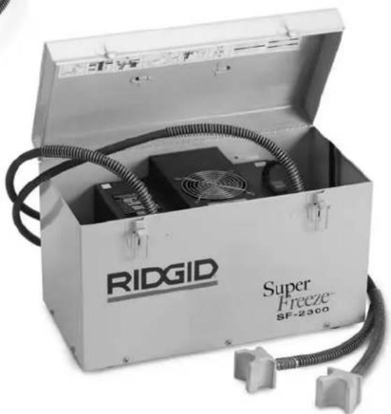
natural_image
Ridgizoo Super Freeze SF-2300 device with open lid and coiled cable (no visible text or symbols on main body)
AVERTISSEMENT
natural_image
Ridgid Super pipe testing setup with tubing and equipment, no visible text or symbols on main componentsnatural_image
Close-up of a metal pipe clamping mechanism with attached black bands, against a textured wall (no text or symbols visible)natural_image
Three technical line drawings of electrical connectors with no text or symbolsnatural_image
Close-up of a damaged electrical cable with exposed insulation and wire (no text or symbols visible)natural_image
Ridgid Super Freeze SF-2500 device with coiled tubing and two metallic connectors (no visible text or symbols on main body)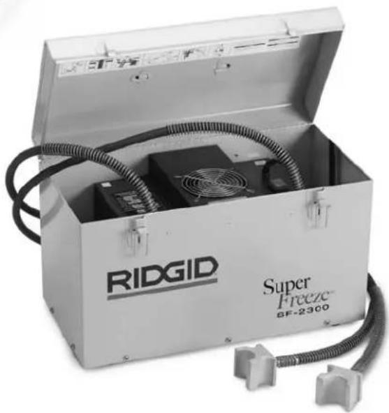
natural_image
Open RIDGID Super Freeze SF-2300 device with coiled tubing and fan (no visible text or symbols on main body)
ADVERTENCIA
natural_image
Two black-and-white icons: a stylized figure with lightning striking a circle and a circular mask (no text or symbols)natural_image
Ridgid Super Freeze water filtration setup with tubing and spray bottle on floor (no text or symbols visible)natural_image
Close-up of a metal pipe joint with a black strap securing it, against a textured wall (no text or symbols visible)natural_image
Three technical line drawings of electrical connectors with wires, no text or symbols presentnatural_image
Close-up of a hand holding a flexible hose with a white foam joint (no text or symbols visible)RIDGID® tools are warranted to be free of defects in workmanship and material.
How long coverage lasts
This warranty lasts for the lifetime of the RIDGID ® tool. Warranty coverage ends when the product becomes unusable for reasons other than defects in workmanship or material.
How you can get service
To obtain the benefit of this warranty, deliver via prepaid transportation the complete product to RIDGE TOOL COMPANY, Elyria, Ohio, or any authorized RIDGID ® INDEPENDENT SERVICE CENTER. Pipe wrenches and other hand tools should be returned to the place of purchase.
What we will do to correct problems
Warranted products will be repaired or replaced, at RIDGE TOOL'S option, and returned at no charge; or, if after three attempts to repair or replace during the warranty period the product is still defective, you can elect to receive a full refund of your purchase price.
What is not covered
Failures due to misuse, abuse or normal wear and tear are not covered by this warranty. RIDGE TOOL shall not be responsible for any incidental or consequential damages.
How local law relates to the warranty
Some states do not allow the exclusion or limitation of incidental or consequential damages, so the above limitation or exclusion may not apply to you. This warranty gives you specific rights, and you may also have other rights, which vary, from state to state, province to province, or country to country.
No other express warranty applies
This FULL LIFETIME WARRANTY is the sole and exclusive warranty for RIDGID ® products. No employee, agent, dealer, or other person is authorized to alter this warranty or make any other warranty on behalf of the RIDGE TOOL COMPANY.

Parts are available online at RIDGIDParts.com

Ridge Tool Company
400 Clark Street
Elyria, Ohio 44035-6001
U.S.A.
Ce qui est couvert
We Build Reputations™
RIDGID

EMERSON
Commercial & Residential Solutions
EMERSON. CONSIDER IT SOLVED.
Printed in U.S.A. 12/13
EC40271 REV. D
© 2013 RIDGID, Inc.
999-998-750.10


- SuperFreeze® Pipe Freezing Units
- ! WARNING!
- General Safety Rules
- Description, Specifications and Standard Equipment
- Safety Symbols
- DANGER
- WARNING
- CAUTION
- NOTICE
- SAVE ALL WARNINGS AND INSTRUCTIONS FOR FUTURE REFERENCE!
- Work Area Safety
- Electrical Safety
- Personal Safety
- Tool Use and Care
- Service
- Pipe Freezing Unit Safety Warnings
- SAVE THESE INSTRUCTIONS!
- Description
- Standard Equipment
- Icons
- Pre-Operation Inspection
- Machine and Work Area Set-Up
- Determine location for freeze plug(s).
- Operating Instructions
- Cleaning
- Accessories
- Machine Storage
- Service and Repair
- Disposal
- AVERTISSEMENT
- ADVERTENCIA
- How long coverage lasts
- How you can get service
- What we will do to correct problems
- What is not covered
- How local law relates to the warranty
- No other express warranty applies
- Ce qui est couvert
Brand : RIDGID
Model : SuperFreeze SF2500
Category : Freezer