USER MANUAL Box In 60 ELICA
EN Instruction on mounting and use


320 mm
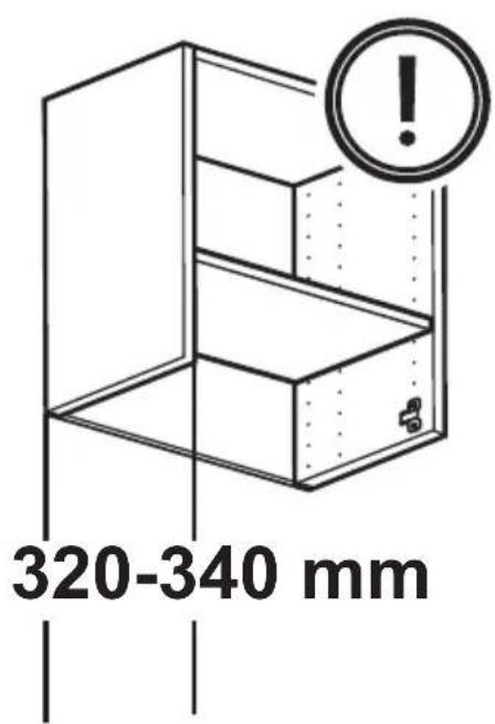


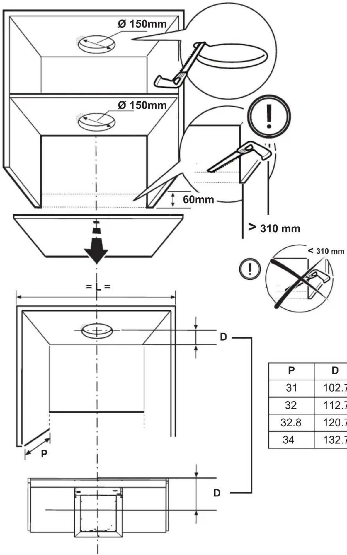
| P | D |
| 31 | 102.7 |
| 32 | 112.7 |
| 32.8 | 120.7 |
| 34 | 132.7 |


1


R
L
2a


.a
.b
.C
.d
5

6


* max 20W 12V (G4)
8
EN - Instruction on mounting and use
Closely follow the instructions set out in this manual. All responsibility, for any eventual inconveniences, damages or fires caused by not complying with the instructions in this manual, is declined. The hood is conceived for the suction of cooking fumes and steam and is destined only for domestic use.
The hood can look different to that illustrated in the drawings in this booklet. The instructions for use, maintenance and installation, however, remain the same.
! It is important to conserve this booklet for consultation at any moment. In the case of sale, cession or move, make sure it is together with the product.
! Read the instructions carefully: there is important information about installation, use and safety.
! Do not carry out electrical or mechanical variations on the product or on the discharge conduits.
! Before proceeding with the installation of the appliance verify that there are no damaged all components. Otherwise contact your dealer and do not proceed with the installation.
Note: the elements marked with the symbol “(*)” are optional accessories supplied only with some models or elements to purchase, not supplied.

Caution
WARNING! Do not connect the appliance to the mains until the installation is fully complete.
Before any cleaning or maintenance operation, disconnect hood from the mains by removing the plug or disconnecting the mains electrical supply.
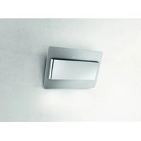
Always wear work gloves for all installation and maintenance operations.
The appliance is not intended for use by children or persons with impaired physical, sensorial or mental faculties, or if lacking in experience or knowledge, unless they are under supervision or have been trained in the use of the appliance by a person responsible for their safety.
This appliance is designed to be operated by adults, children should be monitored to ensure that they do not play with the appliance.
This appliance is designed to be operated by adults. Children should not be allowed to tamper with the controls or play with the appliance.
Never use the hood without effectively mounted grating!
The hood must NEVER be used as a support surface unless specifically indicated.
The premises where the appliance is installed must be sufficiently ventilated, when the kitchen hood is used together with other gas combustion devices or other fuels.
The ducting system for this appliance must not be connected to any existing ventilation system which is being used for any other purpose such as discharging exhaust fumes from appliances burning gas or other fuels.
The flaming of foods beneath the hood itself is severely prohibited.
The use of exposed flames is detrimental to the filters and may cause a fire risk, and must therefore be avoided in all circumstances.
Any frying must be done with care in order to make sure that the oil does not overheat and ignite.
Accessible parts of the hood may become hot when used with cooking appliance.
With regards to the technical and safety measures to be adopted for fume discharging it is important to closely follow the regulations provided by the local authorities.
The hood must be regularly cleaned on both the inside and outside (AT LEAST ONCE A MONTH).
This must be completed in accordance with the maintenance instructions provided in this manual). Failure to follow the instructions provided in this user guide regarding the cleaning of the hood and filters will lead to the risk of fires.
Do not use or leave the hood without the lamp correctly mounted due to the possible risk of electric shocks.
We will not accept any responsibility for any faults, damage or fires caused to the appliance as a result of the non-observance of the instructions included in this manual.
This appliance is marked according to the European directive 2002/96/EC on Waste Electrical and Electronic Equipment (WEEE). By ensuring this product is disposed of correctly, you will help prevent potential negative consequences for the environment and human health, which could otherwise be caused by inappropriate waste handling of this product.

The symbol ■ on the product, or on the documents accompanying the product, indicates that this appliance may not be treated as household waste. Instead it should be taken to the appropriate collection point for the recycling of electrical and electronic equipment. Disposal must be carried out in accordance with local environmental regulations for waste disposal.
For further detailed information regarding the process, collection and recycling of this product, please contact the appropriate department of your local authorities or the local department for household waste or the shop where you purchased this product.
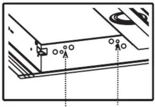
Additional Installation Specifications:
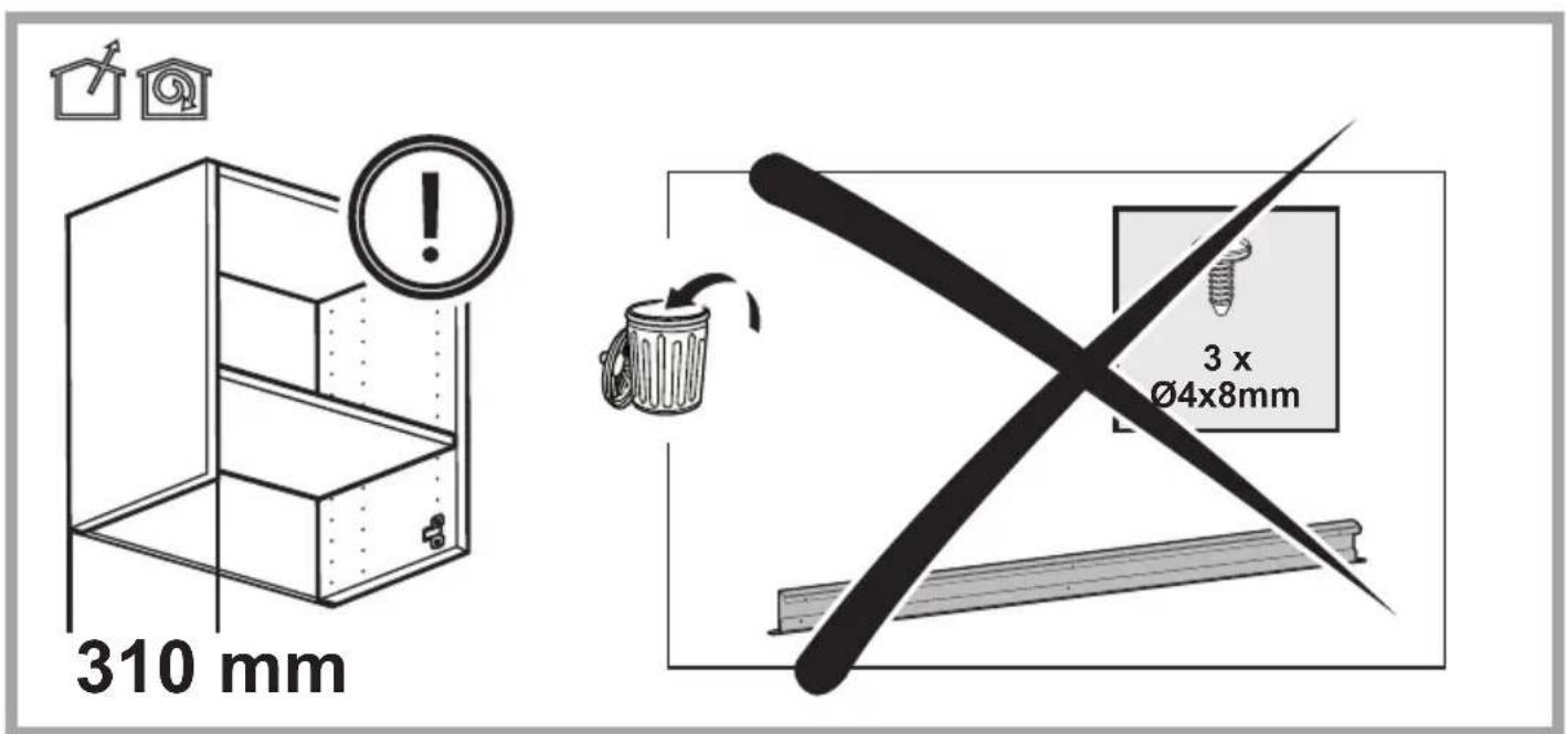
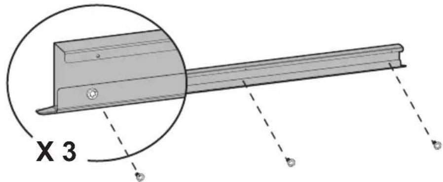
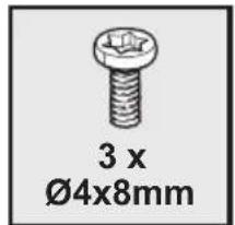
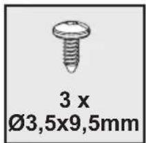
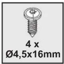
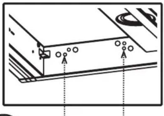
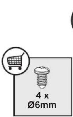
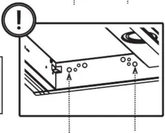
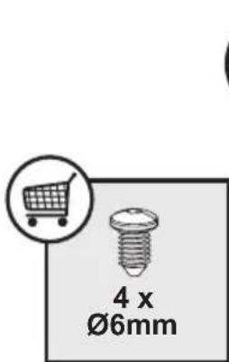
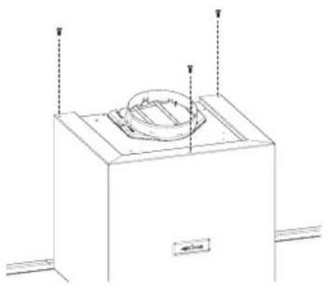
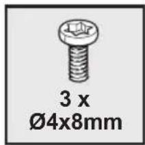
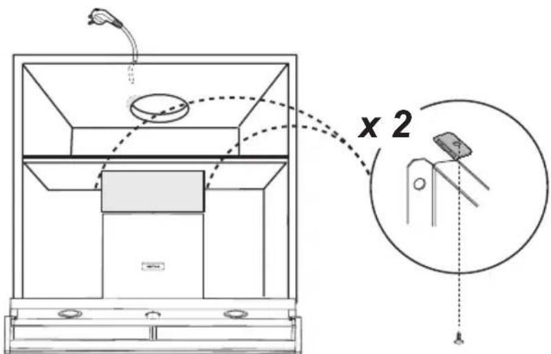
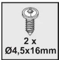
Use only the fixing screws supplied with the product for installation or, if not supplied, purchase the correct screws type.
Use the correct length for the screws which are identified in the Installation Guide.
In case of doubt, consult an authorised service assistance centre or similar qualified person.
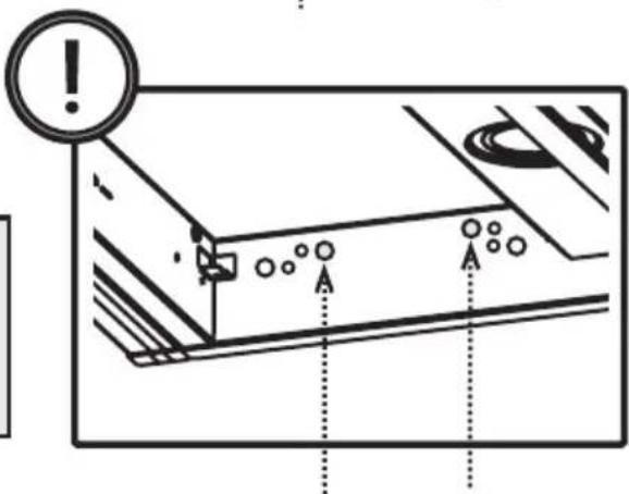
WARNING! Failure to install the screws or fixing device in accordance with these instructions may result in electrical hazards.
Use
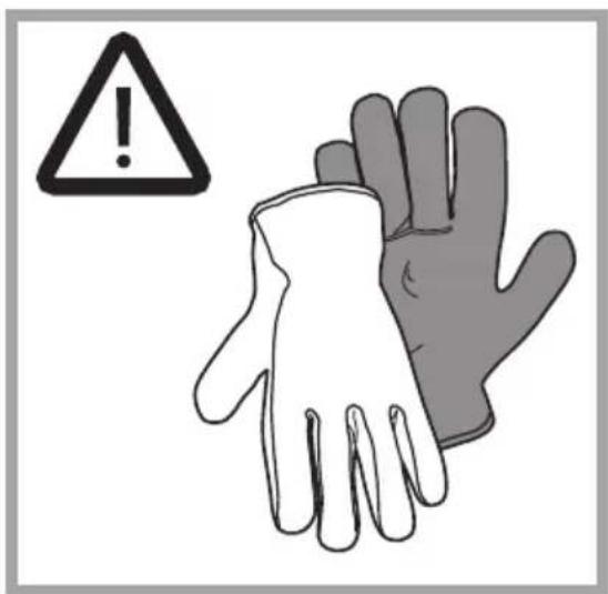
The hood is designed to be used either for exhausting or filter version.

Ducting version
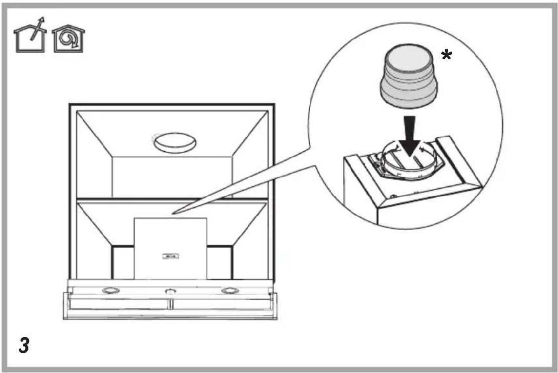
In this case the fumes are conveyed outside of the building by means of a special pipe connected with the connection ring located on top of the hood.
Attention! The exhausting pipe is not supplied and must be purchased apart.
Diameter of the exhausting pipe must be equal to that of the connection ring.
In the horizontal runs the exhausting pipe must be slightly slanted (about 10° ) and directed upwards to vent the air easily from the room to the outside.
Attention! If the hood is supplied with active charcoal filter, then it must be removed.
Connect the hood and discharge holes on the walls with a diameter equivalent to the air outlet (connection flange).
Using the tubes and discharge holes on walls with smaller dimensions will cause a diminution of the suction performance and a drastic increase in noise.
Any responsibility in the matter is therefore declined.
! Use a duct of the minimum indispensable length.
! Use a duct with as few elbows as possible (maximum elbow angle: 90°).
! Avoid drastic changes in the duct cross-section.
! Use a duct as smooth as possible inside.
! The duct must be made of certified material.

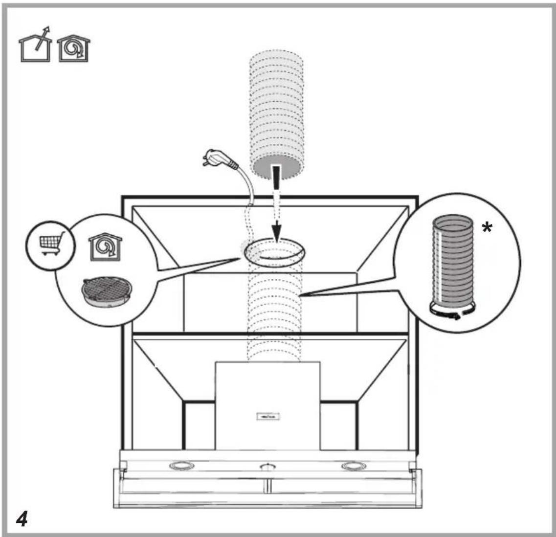
Filter version
One active charcoal filter is needed for this and can be obtained from your usual retailer.
The filter removes the grease and smells from the extracted air before sending it back into the room through the upper outlet grid.
Installation
The minimum distance between the supporting surface for the cooking equipment on the hob and the lowest part of the range hood must be not less than 50cm from electric cookers and 50cm from gas or mixed cookers.
If the instructions for installation for the gas hob specify a greater distance, this must be adhered to.

Electrical connection
The mains power supply must correspond to the rating indicated on the plate situated inside the hood. If provided with a plug connect the hood to a socket in compliance with current regulations and positioned in an accessible area, after installation. If it not fitted with a plug (direct mains connection) or if the plug is not located in an accessible area, after installation, apply a double pole switch in accordance with standards which assures the complete disconnection of the mains under conditions relating to over-current category III, in accordance with installation instructions.
Warning! Before re-connecting the hood circuit to the mains supply and checking the efficient function, always check that the mains cable is correctly assembled.
Warning! Power cable replacement must be undertaken by the authorised service assistance centre or similar qualified person.
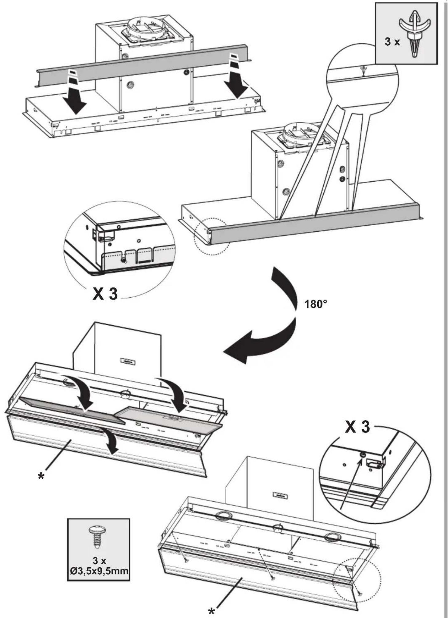
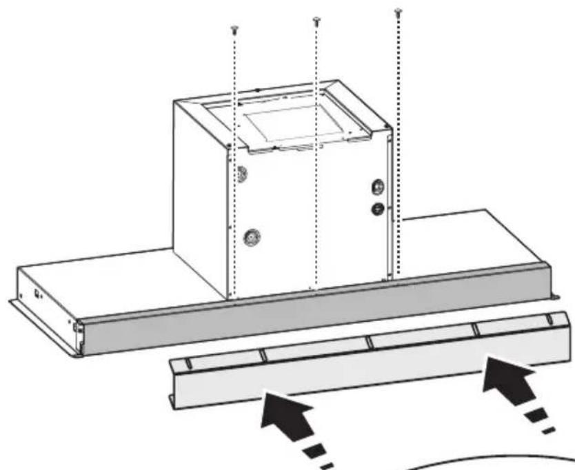
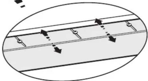
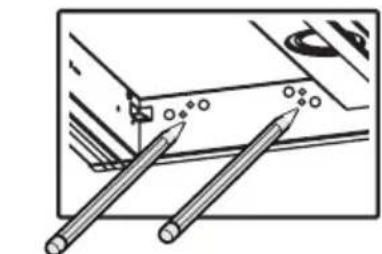
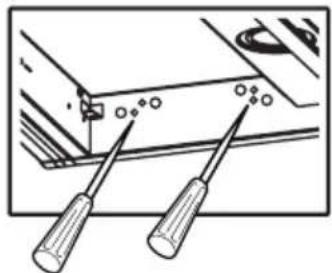
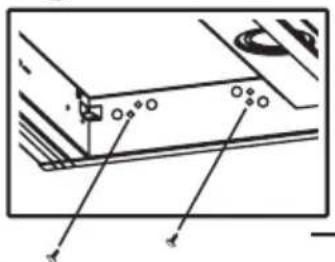
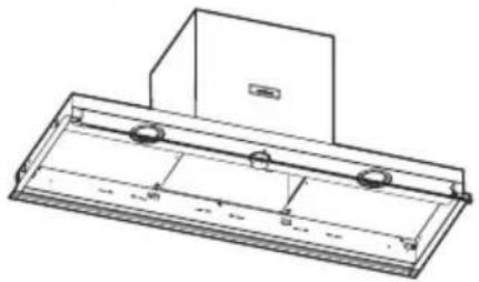
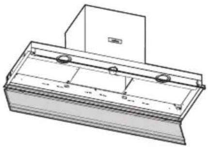
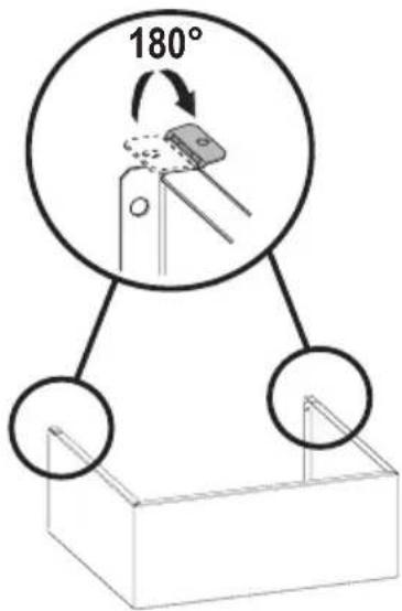
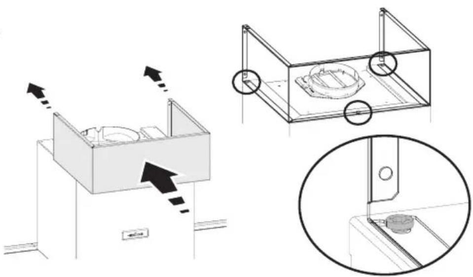
Mounting
Before beginning installation:
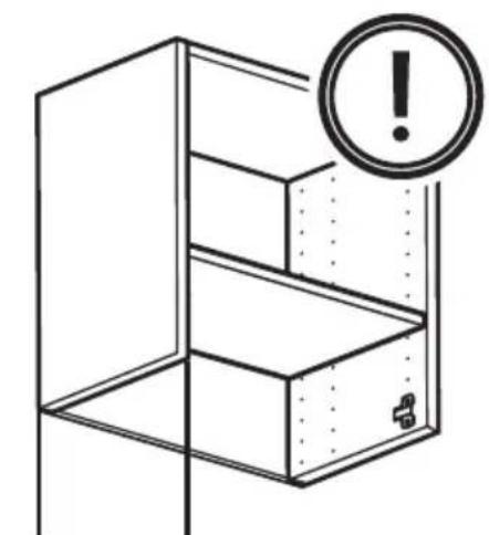
- Check that the product purchased is of a suitable size for the chosen installation area.
- Remove the charcoal (*) filter/s if supplied (see also relative paragraph). This/these is/are to be mounted only if you want to use the hood in the filtering version.
- Check (for transport reasons) that there is no other supplied material inside the hood (e.g. packets with screws (*), guarantees (*), etc.), eventually removing them and keeping them.
- If possible, disconnect and move freestanding or slide-in range from cabinet opening to provide easier access to rear wall/ceiling. Otherwise put a thick, protective covering over countertop, cooktop or range to protect from damage and debris. Select a flat surface for assembling the unit. Cover that surface with a protective covering and place all canopy hood parts and hardware in it.
- In addition check whether near the installation area of the hood (in the area accessible also with the hood mounted) an electric socket is available and it is possible to connect a fumes discharge device to the outside (only suction version).
- Carry out all the masonry work necessary (e.g. installation of an electric socket and/or a hole for the passage of the discharge tube).
In the case of the presence of panels and/or walls and/or lateral wall units check that there is sufficient space to install the hood and that access to the command panel is easy.
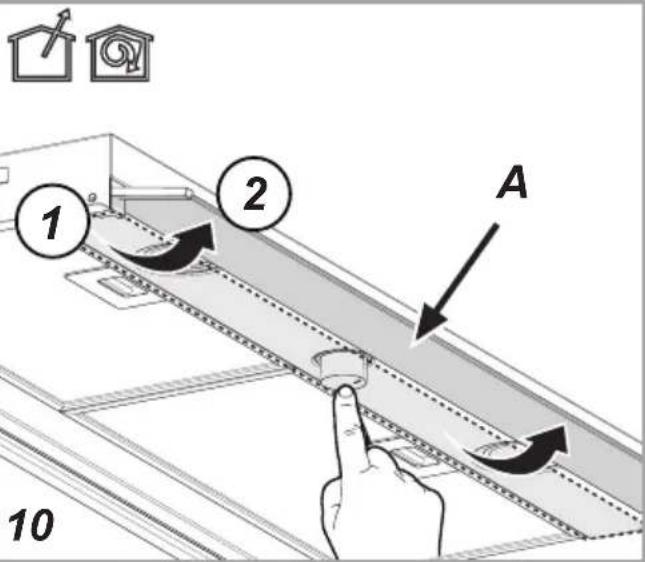
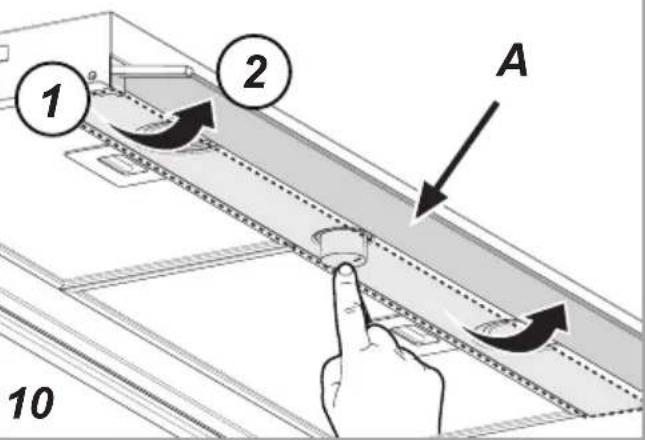
Operation
Use the high suction speed in cases of concentrated kitchen vapours. It is recommended that the cooker hood suction is switched on for 5 minutes prior to cooking and to leave in operation during cooking and for another 15 minutes approximately after terminating cooking.
Always fully open the vapour catcher (A).
Fig. 10
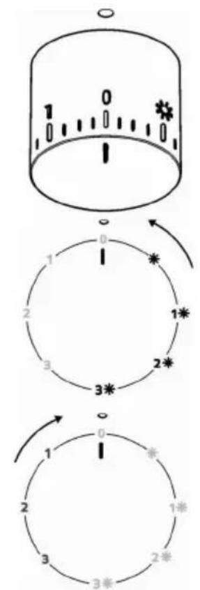
 | Light ON |
1 | Speed 1Light ON |
2 | Speed 2Light ON |
3 | Speed 3Light ON |
 | OFF |
 | Speed 1Light OFF |
 | Speed 2Light OFF |
 | Speed 3Light OFF |
Maintenance
ATTENTION! Before performing any maintenance operation, isolate the hood from the electrical supply by switching off at the connector and removing the connector fuse.
Or if the appliance has been connected through a plug and socket, then the plug must be removed from the socket.
Cleaning
The cooker hood should be cleaned regularly (at least with the same frequency with which you carry out maintenance of the fat filters) internally and externally. Clean using the cloth dampened with neutral liquid detergent. Do not use abrasive products. DO NOT USE ALCOHOL!
WARNING: Failure to carry out the basic cleaning recommendations of the cooker hood and replacement of the filters may cause fire risks.
Therefore, we recommend observing these instructions.
The manufacturer declines all responsibility for any damage to the motor or any fire damage linked to inappropriate maintenance or failure to observe the above safety recommendations.
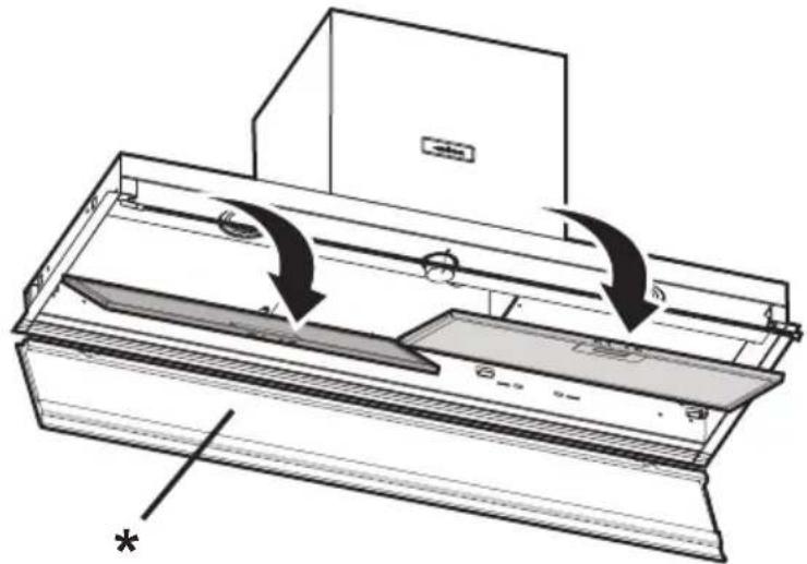
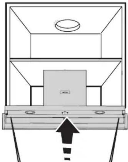
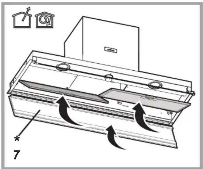
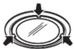
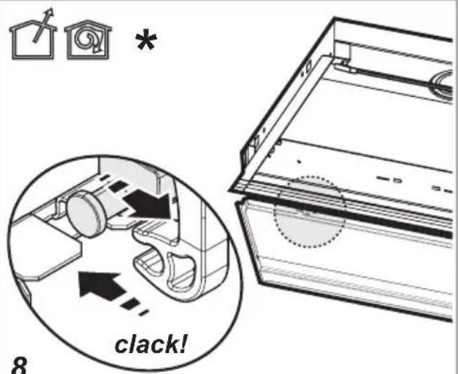
Panel
Fig. 8
Dismantling:
pull the panel out decisively and remove it from all the connecting points.
Cleaning:
the panel should be cleaned with the same frequency as the fat filters, using a cloth soaked in neutral liquid detergents.
Avoid the use of products containing abrasives. DO NOT USE ALCOHOL!
Montage:
The panel should be fixed between the pins placed for this reason on the surface of the hood.
Attention! Always check that the panel is fixed in its place well.
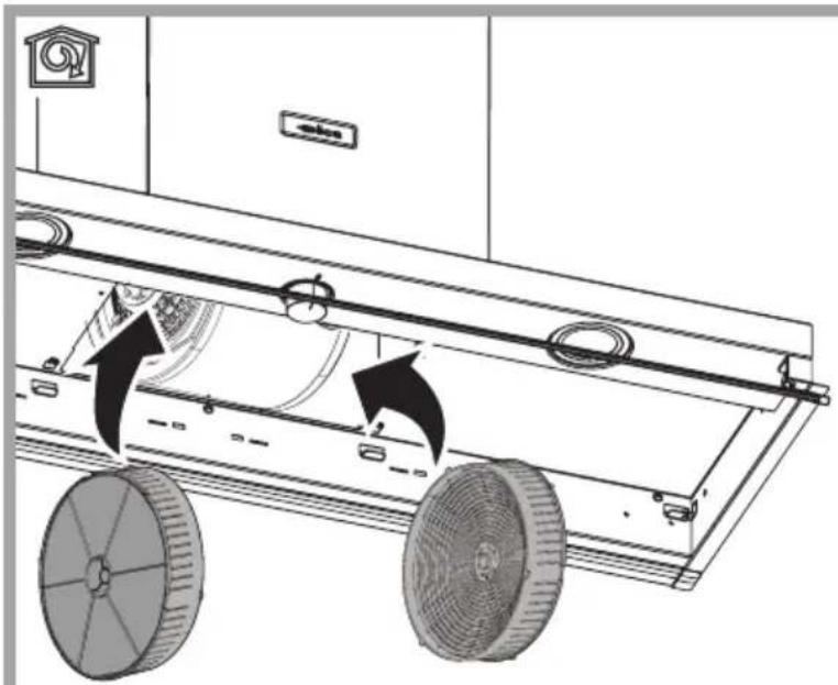
Grease filter
Fig. 1-7
Traps cooking grease particles.
The grease filter must be cleaned once a month using non aggressive detergents, either by hand or in the dishwasher, which must be set to a low temperature and a short cycle. When washed in a dishwasher, the grease filter may discolour slightly, but this does not affect its filtering capacity.
To remove the grease filter, pull the spring release handle.
Charcoal filter (filter version only)
Fig. 6
It absorbs unpleasant odours caused by cooking.
The saturation of the charcoal filter occurs after more or less prolonged use, depending on the type of cooking and the regularity of cleaning of the grease filter.
In any case it is necessary to replace the cartridge at least every four mounths.
The charcoal filter may NOT be washed or regenerated.
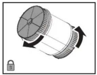
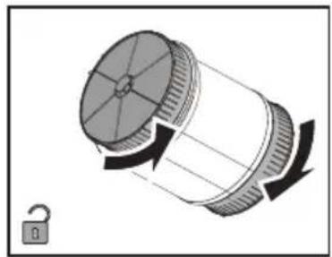
Circular carbon filter
Apply one on each side as cover to both the shield grids of the motor impeller, then turn clockwise.
For the disassembly, turn counter-clockwise.
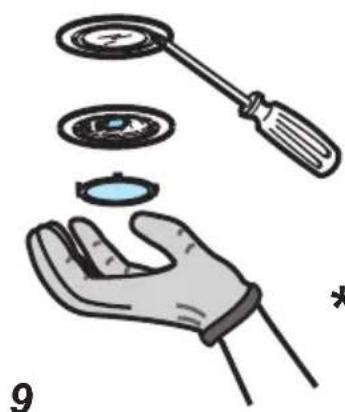
Replacing lamps
Fig. 9
Disconnect the appliance from the electricity.
Warning! Prior to touching the light bulbs ensure they are cooled down.
Replace the old light bulb with the one of the same type as specified in the feature label or near the light lamp on the hood.
- Using a flat head screwdriver or equivalent tool, carefully pry loose the light cover.
-
Remove the damaged light and replace with a new 12 Volt, 20 Watt (Maximum) halogen light made for a G-4 base SUITABLE FOR USE IN OPEN LUMINAIRES. Follow package directions and do not touch new light with bare hands.
-
Reinstall the light cover. (it will snap shut).
If the lights do not work, make sure that the lamps are fitted properly into their housings before you call for technical assistance.
- Model with LED light
The hood is equipped with a lighting system based on LED technology.
The LEDs guarantee an optimum lighting, a duration up to 10 times as long as the traditional lamps and allow to save 90% electrical energy.
For replacement, contact the technical service.
- Malli, jossa on LED lamput
 | Gaisma ON |
1  | Ātrums 1Gaisma ON |
2  | Ātrums 2Gaisma ON |
3  | Ātrums 3Gaisma ON |
 | OFF |
 | Ātrums 1Gaisma OFF |
 | Ātrums 2Gaisma OFF |
| [YWWX] | Ātrums 3Gaisma OFF |