
267922 - Crimping tool MILWAUKEE - Free user manual and instructions
Find the device manual for free 267922 MILWAUKEE in PDF.

| Product Type | Cordless Crimping Tool (crimping pliers) |
| Brand | Milwaukee |
| Model | 267922 |
| Power Source | M18™ 18 V DC Battery |
| Battery Type | M18™ |
| Charger Type | M18™ |
| Crimping Force | 53.4 kN (6 tons) |
| Max. Capacity (jaws 49-16-U000) | Copper 600 MCM / Aluminum 350 MCM |
| Max. Capacity (jaws 49-16-U111) | Copper 750 MCM / Aluminum 750 MCM |
| Operating Temperature | -18 °C to 50 °C |
| Indicator Light | Green (cycle complete), Red (insufficient pressure), Flashing red/green (maintenance due) |
| LED Lighting | 2 built-in LEDs to illuminate work area |
| Connectivity | ONE-KEY™ (module FCC ID BGM220S2/QOQ-BGM220S2) |
| Compatible Jaws | 49-16-U000 (600 MCM Cu), 49-16-U111 (750 MCM Cu), 49-16-2780 (cable cutter) |
| Dies (crimping dies) | Interchangeable, color-coded by gauge (e.g., red #8, blue #6, etc.) |
| Emergency Relief Valve | Allows opening jaws in case of incomplete cycle |
| Maintenance and Cleaning | Clean with a damp cloth and mild soap; do not immerse |
| Internal Button Cell | 3 V CR2032 for ONE-KEY™ |
| Warranty | 5 years (tool), except as noted |
| Safety Standards | Read manual, wear eye protection, work on de-energized lines if possible |
Frequently Asked Questions - 267922 MILWAUKEE
User questions about 267922 MILWAUKEE
0 question about this device. Answer the ones you know or ask your own.
Ask a new question about this device
Download the instructions for your Crimping tool in PDF format for free! Find your manual 267922 - MILWAUKEE and take your electronic device back in hand. On this page are published all the documents necessary for the use of your device. 267922 by MILWAUKEE.
USER MANUAL 267922 MILWAUKEE
WARNING To reduce the risk of injury, user must read and understand operator's manual.
WARNING Read all safety warnings, instructions, illustrations and specifica-
tions provided with this power tool. Failure to follow all instructions listed below may result in electric shock, fire and/or serious injury. Save all warnings and instructions for future reference.
The term "power tool" in the warnings refers to your mains-operated (corded) power tool or battery-operated (cordless) power tool.
WORK AREA SAFETY
- Keep work area clean and well lit. Cluttered or dark areas invite accidents.
- Do not operate power tools in explosive atmospheres, such as in the presence of flammable liquids, gases or dust. Power tools create sparks which may ignite the dust or fumes.
- Keep children and bystanders away while operating a power tool. Distractions can cause you to lose control.
ELECTRICAL SAFETY
- Power tool plugs must match the outlet. Never modify the plug in any way. Do not use any adapter plugs with earthed (grounded) power tools. Unmodified plugs and matching outlets will reduce risk of electric shock.
- Avoid body contact with earthed or grounded surfaces, such as pipes, radiators, ranges and refrigerators. There is an increased risk of electric shock if your body is earthed or grounded.
- Do not expose power tools to rain or wet conditions. Water entering a power tool will increase the risk of electric shock.
- Do not abuse the cord. Never use the cord for carrying, pulling or unplugging the power tool. Keep cord away from heat, oil, sharp edges or moving parts. Damaged or entangled cords increase the risk of electric shock.
- When operating a power tool outdoors, use an extension cord suitable for outdoor use. Use of a cord suitable for outdoor use reduces the risk of electric shock.
- If operating a power tool in a damp location is unavoidable, use a ground fault circuit interrupter (GFCI) protected supply. Use of an GFCI reduces the risk of electric shock.
PERSONAL SAFETY
- Stay alert, watch what you are doing and use common sense when operating a power tool. Do not use a power tool while you are tired or under the influence of drugs, alcohol or medication. A moment of inattention while operating power tools may result in serious personal injury.
- Use personal protective equipment. Always wear eye protection. Protective equipment such as a dust mask, non-skid safety shoes, hard hat or hearing protection used for appropriate conditions will reduce personal injuries.
- Prevent unintentional starting. Ensure the switch is in the off-position before connecting to power source and/or battery pack, picking up or carrying the tool. Carrying power tools with your finger on the switch or energizing power tools that have the switch on invites accidents.
- Remove any adjusting key or wrench before turning the power tool on. A wrench or a key left
attached to a rotating part of the power tool may result in personal injury.
- Do not overreach. Keep proper footing and balance at all times. This enables better control of the power tool in unexpected situations.
- Dress properly. Do not wear loose clothing or jewelry. Keep your hair and clothing away from moving parts. Loose clothes, jewelry or long hair can be caught in moving parts.
- If devices are provided for the connection of dust extraction and collection facilities, ensure these are connected and properly used. Use of dust collection can reduce dust-related hazards.
- Do not let familiarity gained from frequent use of tools allow you to become complacent and ignore tool safety principles. A careless action can cause severe injury within a fraction of a second.
POWER TOOL USE AND CARE
- Do not force the power tool. Use the correct power tool for your application. The correct power tool will do the job better and safer at the rate for which it was designed.
- Do not use the power tool if the switch does not turn it on and off. Any power tool that cannot be controlled with the switch is dangerous and must be repaired.
- Disconnect the plug from the power source and/or remove the battery pack, if detachable, from the power tool before making any adjustments, changing accessories, or storing power tools. Such preventive safety measures reduce the risk of starting the power tool accidentally.
- Store idle power tools out of the reach of children and do not allow persons unfamiliar with the power tool or these instructions to operate the power tool. Power tools are dangerous in the hands of untrained users.
- Maintain power tools and accessories. Check for misalignment or binding of moving parts, breakage of parts and any other condition that may affect the power tool's operation. If damaged, have the power tool repaired before use. Many accidents are caused by poorly maintained power tools.
- Keep cutting tools sharp and clean. Properly maintained cutting tools with sharp cutting edges are less likely to bind and are easier to control.
- Use the power tool, accessories and tool bits etc. in accordance with these instructions, taking into account the working conditions and the work to be performed. Use of the power tool for operations different from those intended could result in a hazardous situation.
- Keep handles and grasping surfaces dry, clean and free from oil and grease. Slippery handles and grasping surfaces do not allow for safe handling and control of the tool in unexpected situations.
BATTERY TOOL USE AND CARE
- Recharge only with the charger specified by the manufacturer. A charger that is suitable for one type of battery pack may create a risk of fire when used with another battery pack.
- Use power tools only with specifically designated battery packs. Use of any other battery packs may create a risk of injury and fire.
-
When battery pack is not in use, keep it away from other metal objects, like paper clips, coins, keys, nails, screws or other small metal objects, that can make a connection from one terminal to another. Shorting the battery terminals together may cause burns or a fire.
-
Under abusive conditions, liquid may be ejected from the battery; avoid contact. If contact accidentally occurs, flush with water. If liquid contacts eyes, additionally seek medical help. Liquid ejected from the battery may cause irritation or burns.
- Do not use a battery pack or tool that is damaged or modified. Damaged or modified batteries may exhibit unpredictable behavior resulting in fire, explosion or risk of injury.
- Do not expose a battery pack or tool to fire or excessive temperature. Exposure to fire or temperature above 265^ (130°C) may cause explosion.
- Follow all charging instructions and do not charge the battery pack or tool outside the temperature range specified in the instructions. Charging improperly or at temperatures outside the specified range may damage the battery and increase the risk of fire.
SERVICE
- Have your power tool serviced by a qualified repair person using only identical replacement parts. This will ensure that the safety of the power tool is maintained
- Never service damaged battery packs. Service of battery packs should only be performed by the manufacturer or authorized service providers.
SPECIFIC SAFETY RULES FOR CRIMPER
- Use tool only as directed. Only trained personnel should operate tool.
WARNING To reduce the risk of arc flash, electric shock and property damage, work on deenergized lines when possible. Tool is not insulated. Should work on energized lines be required, ensure all proper precautions, including those contained in NFPA 70E, have been taken first.
- Use tool only with MILWAUKEE crimping jaw 49-16-U000 or 49-16-U111, "U" dies, and connectors for which they are rated. Jaws, dies, and connectors must be used in an APPROVED COMBINATION to achieve a successful operation. Improper combinations can result in a faulty crimp. Electric shock, fire, explosion, and property damage could occur.
- Do not use tool without jaws installed. Fingers could be injured.
- Keep hands away from jaws while tool is in use. Fingers could be injured.
•To reduce the risk of injury, wear safety goggles or glasses with side shields when operating or servicing the tool.
- Inspect and discard workpieces with cracks or wear before use. Materials may crack or shatter.
- Follow installation specifications as specified in Table A or B using an Approved Combination of jaws, dies, connectors and cables as indicated. Other uses may cause damage to the tool, accessories, and workpiece.
- Chemical Burn Hazard. Keep coin cell battery away from children.
•Always use common sense and be cautious when using tools. It is not possible to anticipate every situation that could result in a dangerous outcome. Do not use this tool if you do not understand these operating instructions or you feel the work is beyond your capability; contact Milwaukee Tool or a trained professional for additional information or training.
- Maintain labels and nameplates. These carry important information. If unreadable or missing, contact a MILWAUKEE service facility for a free replacement.
WARNING Some dust created by power sanding, sawing, grinding, drilling, and other construction activities contains chemicals known to cause cancer, birth defects or other reproductive harm. Some examples of these chemicals are:
- lead from lead-based paint
- crystalline silica from 'bricks and cement and other masonry products, and
• arsenic and chromium from chemically-treated lumber. Your risk from these exposures varies, depending on how often you do this type of work. To reduce your exposure to these chemicals: work in a well ventilated area, and work with approved safety equipment, such as those dust masks that are specially designed to filter out microscopic particles.
SPECIFICATIONS
Cat. No....2679-20
Volts 18 DC
Battery Type ......M18™
Charger Type ......M18™
Module/FCC ID ......BGM220S2/QOQ-BGM220S2
Force 6 Tons
Recommended Ambient Operating Temperature 0°F to 122°F
Crimping Jaws
Cat. No....49-16-U000
Jaw Type ......M18™ 600 MCM U Style
Crimping Jaw
Max. Crimping Capacity ....600 MCM
Cu/350 MCM Al
Cat. No....49-16-U111
Jaw Type ......M18™ 750 MCM U Style
Crimping Jaw
Max. Crimping Capacity ....750 MCM
Cu/750 MCM Al
Cable Cutting Jaws
Cat. No 49-16-2780
Jaw Type ......M18™ 750 MCM Cu/1000 MCM AI
Cable Cutting Jaws
Max. Cutting Capacity ....750 MCM
Cu/1000 MCM AI
Replacement Blades ...... Cat. No. 48-44-0411
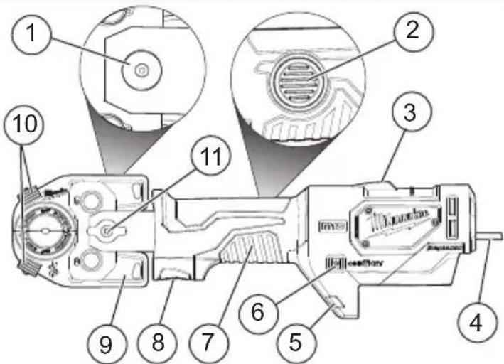
FUNCTIONAL DESCRIPTION
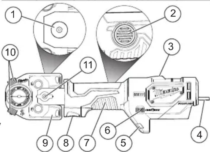
- Locking thumb screw
- Backup release valve
- Crimping indicator
- Hanger
- LEDs
-
ONE-KEY ^TM indicator
-
Handle
- Trigger
- Crimping jaws
- Die release tabs
- Retaining pin
Connections made with tool 2779-20 or 2679-20 with jaw 49-16-U000 or 49-16-U111 and combination of die and connector part numbers in the charts below produce UL classified crimps according to the UL 486A-B standard.
Table A - United States

| Copper Short & Long Barrel Lugs & Splices | |||||||||||
| Anderson | Blackburn ^ | Burndy | ILSCO | Panduit | Penn-Union | T&B | |||||
| Splice Model #'s | VHSS & VHS | CSP & CU | YS, YS-L, YS-T | CT & CTL | SCSS, SCS, SCL, SCH | BCU & BBCU | 54504-54523-TB & 54804-54823 | ||||
| Lug Model #'s | VHCS & VHCL | CTL-2, CTL, CTL-L, LCN | YA, YAZ, YA-L, YA-2L, YA-2LN, YA-L-NT, YA-L-2NT, YA-L-TC, YA-L-2TC, YA-2N, YA-TC, YA-2TC | CLN, CLND, CLNS, CLW, CLWD, CRA, CRB, CRA-L, CRB-L, CRA-2L, CRB-2L, CSW, CSWS | LCA, LCAS LCB, LCC, LCD | BLU & BBLU | 54104-54123-TB, 54204-54223, 54850BE-54880BE, 54930BE-54923BE | ||||
| Wire Size (Code Only) | Die Color Cat. No. | Die Indentation Mark | Lugs: Total # of CrimpsSplices: # of Crimps per Side | ||||||||
| Anderson Blackburn ^ | Burndy IL | SCO Panduit Penn-Union T&B | |||||||||
| #8 AWG RED | 49-16-U | 008C 8 | 1 1 1 1 1 1 | ||||||||
| #6 AWG + BLUE | 49-16-U | 006C 6 | |||||||||
| #4 AWG GRAY | 49-16-U | 004C 4 | 1 | ||||||||
| #2 AWG + | BROWN | 49-16-U | 002C | 2 | |||||||
| #1 AWG + | GREEN | 49-16-U | 001C | 1 | |||||||
| 1/0 AWG | PINK | 49-16-U | 01AC | 1/0 | |||||||
| 2/0 AWG | BLACK | 49-16-U | 02AC | 2/0 | 2 | 2 2 2 2 2 2 | |||||
| 3/0 AWG | ORANGE | 49-16-U | 03AC | 3/0 | |||||||
| 4/0 AWG | PURPLE | 49-16-U | 04AC | 4/0 | |||||||
| 250 MCM | YELLOW | 49-16-U | 250C | 50 | |||||||
| 300 MCM | WHITE | 49-16-U | 300C 300 | ||||||||
| 350 MCM RED | 49-16-U | 350C 350 | Lugs: 2 Splices: N/A | ||||||||
| 400 MCM BLUE | 49-16-U | 400C 400 | |||||||||
| 500 MCM | BROWN | 49-16-U | 500C 500 | ||||||||
| 600 MCM | GREEN | 49-16-U | 600C 600 | ||||||||
| 750 MCM | BLACK | 49-16-U | 750C * | 750 | 3 | 3 | 3 | 3 | 3 | 3 | |
- Concentric or Compressed only. * Connections must use jaw 49-16-U111.
Dual Rated Lugs & Splices
| Anderson | Blackburn^® | Burndy | ILSCO | Panduit | Penn-Union | T&B | |||||
| Splice Model #’s | VACS | ASP | YS-A | AS & ASN | SA | BCUA | 60501-60578 | ||||
| Lug Model #’s V | ACL ATL | YA-A& YA-ATN | ACL, ACN, ALND, ALNS,2ACL, 2ACN, ALNN | LAA & LAB | BLUA | 60101-6017860230-60278 | |||||
| Wire Size(Code Only) | Die Color | Cat. No. | Die Indentation Mark | Lugs: Total # of CrimpsSplices: # of Crimps per Side | |||||||
| Anderson | Blackburn^® | Burndy | ILSCO | Panduit | Penn-Union | T&B | |||||
| #8 AWG | BLUE | 49-16-U008 | 8 | Lugs: N/ASplices: 2 | Lugs: 2Splices: N/A | 2 | 2 | Lugs: 2Splices: N/A | 2 | ||
| #6 AWG | GRAY | 49-16-U006 | 6 | ||||||||
| #4 AWG | GREEN | 49-16-U004 | 4 | ||||||||
| #2 AWG | PINK | 49-16-U002 | 2 | 2 | 2 | 2 | |||||
| #1 AWG | GOLD | 49-16-U001 | 1 | 3 | 3 | 3 | 3 | 3 | 3 | 3 | |
| 1/0 AWG TAN | 49-16-U01A | 1/0 | |||||||||
| 2/0 AWG | OLIVE | 49-16-U02A | 2/0 | ||||||||
| 3/0 AWG | RUBY 49 | -16-U03A | 3/0 | ||||||||
| 4/0 AWG | WHITE | 49-16-U04A | 4/0 | 4 | 4 | 4 | 4 | 4 | 4 | 4 | |
| 250 MCM RED | 49-16-U250 | 250 | |||||||||
| 300 MCM | BLUE 49 | -16-U300 | 300 | ||||||||
| 350 MCM | BROWN | 49-16-U350 | 350 | ||||||||
| 400 MCM | GREEN | 49-16-U400 * | 400 | 4 | Lugs: 4Splices: N/A | 4 | 4 | 4 | Lugs: N/ASplices: 4 | 4 | |
| 500 MCM | PINK | 49-16-U500 * | 500 | 4** | Lugs: 5Splices: N/A | ||||||
| 600 MCM BLACK | 49-16-U600 * 600 | Lugs: 4**Splices: N/A | |||||||||
| 750 MCM | YELLOW | 49-16-U750 * | 750 | 4 | 4 | ||||||
* Connections must use jaw 49-16-U111. ** Aluminum wire only.
Number of crimps is a minimum. Additional crimps would not negatively affect the integrity of the connection so long as they are uniformly placed between the intended crimp area of the connector, typically outlined with color bands or knurls. For the latest listing of approvals, visit milwaukeetool.com.
Connections made with tool 2779-20 or 2679-20 with jaw 49-16-U000 or 49-16-U111 and combination of die and connector part numbers in the charts below produce UL classified crimps according to the UL 486A-B standard.
Table B - Canada and Mexico

| Copper Short & Long Barrel Lugs & Splices | ||||||||||
| Anderson | Blackburn® | Burndy | ILSCO | Panduit | Penn-Union | T&B | ||||
| Splice Model #'s | VHSS & VHS | CSP & CU | YS, YS-L, YS-T | CT & CTL | SCSS, SCS, SCL, SCH | BCU & BBCU | 54504-54523-TB & 54804-54823 | |||
| Lug Model #'s | VHCS & VHCL | CTL-2, CTL, CTL-L, LCN | YA, YAZ, YA-L, YA-2L, YA-2LN, YA-L-NT, YA-L-2NT, YA-L-TC, YA-L-2TC, YA-2N, YA-TC, YA-2TC | CLN, CLND, CLNS, CLW, CLWD, CRA, CRB, CRA-L, CRB-L, CRA-2L, CRB-2L, CSW, CSWS | LCA, LCAS LCB, LCC, LCD | BLU & BBLU | 54104-54123-TB, 54204-54223, 54850BE-54880BE, 54930BE-54923BE | |||
| Wire Size (Code Only) | Die Color | Cat. No. | Die Indentation Mark | Lugs: Total # of CrimpsSplices: # of Crimps per Side | ||||||
| Anderson | Blackburn® | Burndy | ILSCO | Panduit | Penn-Union | T&B | ||||
| #8 AWG | RED | 49-16-U008C | 8 | 1 | 11 | 1 | 1 | 1 | ||
| #6 AWG | BLUE | 49-16-U006C | 6 | |||||||
| #4 AWG | GRAY | 49-16-U004C | 4 | 1 | 1 | 1 | ||||
| #2 AWG | BROWN | 49-16-U002C | 2 | |||||||
| #1 AWG | GREEN | 49-16-U001C | 1 | |||||||
| 1/0 AWG | PINK | 49-16-U01AC | 1/0 | 1 | 1 | 1 | 1 | 1 | 1 | 1 |
| 2/0 AWG BLACK 49-16-U02AC | 2/0 | 2 | 2 | 22 | 222 | |||||
| 3/0 AWG | ORANGE | 49-16-U03AC | 3/0 | |||||||
| 4/0 AWG | PURPLE | 49-16-U04AC | 4/0 | |||||||
| 250 MCM | YELLOW | 49-16-U250C 250 | ||||||||
| 300 MCM | WHITE | 49-16-U300C 300 | ||||||||
| 350 MCM | RED | 49-16-U350C 350 | Lugs: 2 Splices: N/A | |||||||
| 400 MCM | BLUE | 49-16-U400C 400 | ||||||||
| 500 MCM | BROWN | 49-16-U500C 500 | ||||||||
| 600 MCM | GREEN | 49-16-U600C 600 | ||||||||
| 750 MCM | BLACK | 49-16-U750C * | 750 | 3 | 3 | 3 | 3 | 3 | 3 | |
* Connections must use jaw 49-16-U111.
Dual Rated Lugs & Splices
| Anderson Blackburn® | Burndy ILSCO Panduit Penn-Union T&B | |||||||||||
| Splice Model #'s | VACS | ASP | YS-A | AS & ASN | SA | BCUA | 60501-60578 | |||||
| Lug Model #'s V | ACL ATL | YA-A& YA-ATN | ACL, ACN, ALND, ALNS,2ACL, 2ACN, ALNN | LAA & LAB | BLUA | 60101-6017860230-60278 | ||||||
| Wire Size(Code Only) | DieColor Cat. No. | DieIndentationMark | Lugs: Total # of CrimpsSplices: # of Crimps per Side | |||||||||
| Anderson | Blackburn® | Burndy | ILSCO | Panduit | Penn-Union | T&B | ||||||
| #8 AWG | BLUE | 49-16-U008 | 8 | Lugs: N/ASplices: 2 | Lugs: 2Splices: N/A | 2 | 2 | Lugs: 2Splices: N/A | 2 | |||
| #6 AWG | GRAY | 49-16-U006 | 6 | |||||||||
| #4 AWG GREEN | 49-16-U004 | 4 | ||||||||||
| #2 AWG | PINK | 49-16-U002 | 2 | 2 | 2 | 2 | ||||||
| #1 AWG | GOLD | 49-16-U001 | 1 | 3 | 3 | 3 | 3 | 3 | 3 | 3 | ||
| 1/0 AWG | TAN | 49-16-U01A | 1/0 | |||||||||
| 2/0 AWG | OLIVE | 49-16-U02A | 2/0 | |||||||||
| 3/0 AWG | RUBY | 49-16-U03A | 3/0 | |||||||||
| 4/0 AWG WHITE | 49-16-U04A | 4/0 | 4 | 4 | 4 | 4 | 4 | 4 | 4 | |||
| 250 MCM | RED | 49-16-U250 | 250 | |||||||||
| 300 MCM | BLUE | 49-16-U300 | 300 | |||||||||
| 350 MCM | BROWN | 49-16-U350 | 350 | |||||||||
| 400 MCM | GREEN | 49-16-U400 * | 400 | 4 | Lugs: 4Splices: N/A | 4 | 4 | 4 | Lugs: N/ASplices: 4 | 4 | ||
| 500 MCM | PINK | 49-16-U500 * | 500 | 4** | Lugs: 5Splices: N/A | |||||||
| 600 MCM | BLACK | 49-16-U600 * | 600 | Lugs: 4**Splices: N/A | ||||||||
| 750 MCM | YELLOW | 49-16-U750 * | 750 | 4 | 4 | |||||||
* Connections must use jaw 49-16-U111. ** Aluminum wire only.
Number of crimps is a minimum. Additional crimps would not negatively affect the integrity of the connection so long as they are uniformly placed between the intended crimp area of the connector, typically outlined with color bands or knurls. For the latest listing of approvals, visit milwaukeetool.com.
Connections made with tool 2779-20 or 2679-20 with jaw 49-16-U000 or 49-16-U111 and combination of die and connector part numbers in the charts below produce UL classified crimps according to the UL 486A-B standard.

E468689
Copper Short & Long Barrel Lugs & Splices
| E468689 | Anderson Blackburn * | Burndy | ILSCO | Panduit | Penn-Union | T&B | ||||
| Splice Models | VHSS & VHS | CSP & CU | YS, YS-L, YS-T | CT & CTL | SCSS, SCS,SCL & SCH | BCU & BBCU | 54504-54523-TB &54804-54823 | |||
| Lug Models | VHCS & VHCL | CTL-2, CTL,CTL-L & LCN | YA, YAZ, YA-L, YA-2L, YA-2LN,YA-L-NT, YA-L-2NT, YA-L-TC,YA-L-2TC, YA-2N, YA-TC,YA-2TC | CLN, CLND, CLNS, CLW,CLWD, CRA, CRB, CRA-L,CRB-L, CRA-2L, CRB-2L,CSW, CSWS | LCA, LCAS,LCB, LCC,LCD | BLU & BBLU | 54104-54123-TB,54204-54223,54850BE-54880BE,54930BE-54923BE | |||
| Wire Size(Code only) | DieColor Cat. No. | DieIndentationMark | Lugs: Total # of CrimpsSplices: # of Crimps per Side | |||||||
| Anderson Blackburn * Burndy | ILSCO Panduit Penn-Union T&B | |||||||||
| #8 AWG | RED | 49-16-U008C -3 | 1 1 1 1 1 1 | |||||||
| #6 AWG | BLUE | 49-16-U006C -6 | ||||||||
| #4 AWG | GRAY | 49-16-U004C -4 | 1 | |||||||
| #2 AWG | BROWN | 49-16-U002C -2 | ||||||||
| #1 AWG | GREEN | 49-16-U001C -1 | Lugs: N/ASplices: 1 | |||||||
| 1/0 AWG | PINK | 49-16-U01AC -1/0 | 1 | |||||||
| 2/0 AWG | BLACK | 49-16-U02AC -2/0 | 2 | 2 2 2 2 2 2 | ||||||
| 3/0 AWG | ORANGE | 49-16-U03AC -3/0 | ||||||||
| 4/0 AWG | PURPLE | 49-16-U04AC -4/0 | ||||||||
| 250 MCM | YELLOW | 49-16-U250C -250 | ||||||||
| 300 MCM | WHITE | 49-16-U300C -300 | ||||||||
| 350 MCM | RED | 49-16-U350C -350 | Lugs: 2Splices: N/A | |||||||
| 400 MCM | BLUE | 49-16-U400C -400 | ||||||||
| 500 MCM | BROWN | 49-16-U500C -500 | ||||||||
| 600 MCM | GREEN | 49-16-U600C -600 | ||||||||
| 750 MCM | BLACK | 49-16-U750C * 750 3 3 3 3 3 3 | ||||||||
* Connections must use jaw 49-16-U111.
Dual Rated Lugs & Splices
| Anderson | Blackburn^® | Burndy | ILSCO | Panduit | Penn-Union | T&B | |||||||||
| Splice Models | VACS | ASP | YS-A | AS & ASN | SA | BCUA | 60501-60578 | ||||||||
| Lug Models | VACL ATL | YA-A& YA-ATN | ACL, ACN, ALND, ALNS,2ACL, 2ACN, ALNN | LAA & LAB BLUA | 60101-6017860230-60278 | ||||||||||
| Wire Size(Code only) | DieColor | Cat. No. | DieIndentationMark | Lugs: Total # of CrimpsSplices: # of Crimps per Side | |||||||||||
| Anderson Blackburn® | Burndy | ILSCO | Panduit | Penn-Union | T&B | ||||||||||
| #8 AWG | BLUE | 49-16-U008 | 8 | Lugs: N/ASplices: 2 | Lugs: 2Splices: N/A | 2 | 2 | Lugs: 2Splices: N/A | 2 | ||||||
| #6 AWG | GRAY | 49-16-U006 | 6 | ||||||||||||
| #4 AWG | GREEN | 49-16-U004 | 4 | ||||||||||||
| #2 AWG | PINK | 49-16-U002 | 2 | 2 | 2 | 2 | |||||||||
| #1 AWG | GOLD | 49-16-U001 | 1 | 3 | 3 | 3 | 3 | 3 | 3 | 3 | |||||
| 1/0 AWG | TAN | 49-16-U01A | 1/0 | ||||||||||||
| 2/0 AWG | OLIVE | 49-16-U02A | 2/0 | ||||||||||||
| 3/0 AWG | RUBY | 49-16-U03A | 3/0 | ||||||||||||
| 4/0 AWG | WHITE | 49-16-U04A | 4/0 | 4 | 4 | 4 | 4 | 4 | 4 | 4 | |||||
| 250 MCM | RED | 49-16-U250 | 250 | ||||||||||||
| 300 MCM | BLUE | 49-16-U300 | 300 | ||||||||||||
| 350 MCM | BROWN | 49-16-U350 | 350 | ||||||||||||
| 400 MCM | GREEN | 49-16-U400* | -400 | 4 | Lugs: 4Splices: N/A | 4 | 4 | 4 | Lugs: N/ASplices: 4 | 4 | |||||
| 500 MCM | PINK | 49-16-U500* | -500 | Lugs: N/ASplices: 4 | |||||||||||
| 600 MCM | BLACK | 49-16-U600* | 600 | Lugs: 4**Splices:N/A | |||||||||||
| 750 MCM | YELLOW | 49-16-U750* | -750 | Lugs: 4Splices: N/A | 4 | 4 | 4 | ||||||||
* Connections must use jaw 49-16-U111. ** Aluminum wire only.
Number of crimps is a minimum. Additional crimps would not negatively affect the integrity of the connection so long as they are uniformly placed between the intended crimp area of the connector, typically outlined with color bands or knurls. For the latest listing of approvals, visit milwaukeetool.com.

AWARNING To reduce the risk of arc flash, electric shock and property damage, work on deenergized lines when possible. Tool is not insulated. Should work on energized lines be required, ensure all proper precautions, including those contained in NFPA 70E, have been taken first.

⚠️WARNING Keep hands away from jaws while tool is in use. Fingers could be injured.

reduce the risk of injury, wear safety goggles or glasses with side shields when operating or servicing the tool.

I operator's manual.

erwriters Laboratories, Inc.
ASSEMBLY
WARNING Recharge only with the charger specified for the battery. For specific charging instructions, read the operator's manual supplied with your charger and battery.
Removing/Inserting the Battery
To remove the battery, push in the release buttons and pull the battery pack away from the tool.
WARNING Always remove the battery pack any time the tool is not in use.
To insert the battery, slide the pack into the body of the tool. Make sure it latches securely into place.
WARNING Only use accessories specifically recommended for this tool. Others may be hazardous.
Inserting/Removing the Crimping Jaws
- WARNING! Remove battery to avoid starting the tool
- Remove the locking thumb screw (when used) from the back of the retaining pin.
- Push in, then rotate the retaining pin counterclockwise 90^ . The pin will pop out.
- Insert the crimping jaws. Line up the center hole with the retaining pin.
- Push in the retaining pin, then rotate clockwise 90^
- Insert and hand tighten the locking thumb screw. NOTE: Use the locking thumb screw to prevent the retaining pin from being unintentionally loosened. A loose retaining pin may damage the tool.
- Rotate the jaws to the desired angle.
⚠️ CAUTION To avoid damage to the tool, do not operate the tool without the retaining pin fully inserted and locked into position. Damage to the cylinder may occur.
AWARNING An incomplete or faulty crimp could cause a fire. Use tool only with MILWAUKEE crimping jaw 49-16-U000 or 49-16-U111, "U" dies, and connectors for which they are rated. Jaws, dies, and connectors must be used in an approved combination to achieve a successful operation. Improper combinations can result in a faulty crimp. Electric shock, fire, explosion, and property damage could occur.
Changing the Dies
Inspect dies and connectors before use. Only use properly matched dies and connectors for the crimping jaws. Refer to Table A or B for die/connector compatibility.
- WARNING! Remove battery to avoid starting the tool.
- Open jaws by squeezing back of crimping head together.
- Snap the appropriate dies into each side of the crimping jaws. Release the jaws.
- To remove, open jaws by squeezing back of crimping head together. Pull out the die release tabs. Pull dies out from crimping jaws.
ONE-KEY™
To learn more about the ONE-KEY™ functionality for this tool, go to milwaukeetool.com/One-Key. To download the ONE-KEY™ app, visit the App Store ® or Google Play™ from your smart device.
| ONE-KEYTM Indicator | |
| Solid Blue | Wireless mode is active and ready to be configured via the ONE-KEYTM app. |
| Blinking Blue | Tool is actively communicating with the ONE-KEYTM app. |
| Blinking Red | Tool is in security lockout and can be unlocked by the owner via the ONE-KEYTM app. |
Cutting Jaws (not included)
The Crimper is compatible with the following MILWAUKEE cutting jaws. Refer to the cutting jaws' instructions for use.
| Jaw Type | Maximum Capacity |
| 750 MCM Cu/AL Jaws(Cat. No. 49-16-2780) | 750 MCM Cu/1000MCM Al |
OPERATION
WARNING
To reduce the risk of arc flash, electric shock and property
damage, work on deenergized lines when possible. Tool is not insulated. Should work on energized lines be required, ensure all proper precautions, including those contained in NFPA 70E, have been taken first.
Keep hands away from crimping jaws
while tool is in use. Fingers could be crushed.

Always wear proper eye protection marked to comply with ANSI Z87.1.
Crimping
Before crimping:
- Inspect the jaws and dies for cracks or other damage. Do not use damaged jaws or dies. Contact a MILWAUKEE service facility.
- Ensure retaining pin is properly seated and dies are properly installed.
- Jaws, dies, connectors, and cables must be used in an APPROVED COMBINATION. Improper combinations can result in a faulty crimp.
- Inspect and discard workpieces with cracks or wear before use. Materials may crack or shatter.
- Follow installation specifications as specified in Table A or B using an Approved Combination of jaws, dies, connectors and cables as indicated. Other uses may cause damage to the tool, accessories, and workpiece.
- Insert battery pack.
- Place jaws with installed dies around the connector
- Hold tool securely. Press and hold the trigger.
- When the cycle is complete the tool will switch off and the indicator will light. Release the trigger.
| LED Indicator Definition | |
| Solid Green Tool completed the operation and reached full crimping pressure. | |
| Solid Red Tool completed the operation but did NOT reach full crimping pressure. | |
| Flashing Red Tool did NOT complete the operation. | |
| Flashing Red/Green (after Solid Green or Solid Red) | Tool has reached its service interval (40,000 crimps). Red/Green flashing will begin after the solid Red or Green indicator for the operation is displayed. MILWAUKEE recommends that the tool be inspected and preventative maintenance completed. Return tool to a MILWAUKEE service facility. |
- Continue crimping according to the instructions in Table A or B, or the connector manufacturer's installation instructions.
- Crimps should be uniformly placed on the barrel of the connector.
- Crimps should be reasonably placed within the color bands or knurled area of the connector.
- For splices, begin crimping in the center, working outward while alternating sides.
- For lugs, begin crimping near the pad, working towards the barrel.
-
The orientation of the crimp is not critical on seamless barrel connectors, but for best results rotate the tool 180^ between crimps.
-
Two LEDs will light the workpiece when the trigger is pulled.
- The die identifier is pressed into the connector during the crimp.
Backup Release Valve
If the jaws need to be opened without completing the cycle, press and hold the backup release valve. Hold tool securely until the cylinder retracts fully.
MAINTENANCE
WARNING
To reduce the risk of injury, always unplug the charger and remove the battery pack from the charger or tool before performing any maintenance. Never disassemble the battery pack, charger, or tool, except as provided in these instructions. Contact a MILWAUKEE service facility for all other repairs.
Maintaining Tool
Keep your tool, battery pack and charger in good repair by adopting a regular maintenance program. Inspect your tool for issues such as undue noise, misalignment or binding of moving parts, breakage of parts, or any other condition that may affect the tool operation. Return the tool, battery pack, and charger to a MILWAUKEE service facility for repair. After six months to one year, depending on use, return the tool, battery pack and charger to a MILWAUKEE service facility for inspection.
If the tool does not start or operate at full power with a fully charged battery pack, clean the contacts on the battery pack. If the tool still does not work properly, return the tool, charger and battery pack, to a MILWAUKEE service facility for repairs.
ONE-KEY™
Refer to the ONE-KEY App for information regarding necessary servicing, such as internal battery life and crimp count.
WARNING
Chemical Burn Hazard. This device contains a coin cell battery. A new try can cause severe in- and lead to death in as little as 2 hours if swallowed or enters the body. Always secure the battery cover. If it does not close securely, stop using the device, remove the batteries, and keep it away from children. If you think batteries may have been swallowed or entered the body, seek immediate medical attention.

Internal Coin Cell Battery
An internal coin cell battery is used to facilitate full ONE-KEY ^™ functionality.
To replace the coin cell battery:
- WARNING! Remove tool's battery to avoid starting the tool.
- Loosen the screw(s) and open the coin cell battery door.
- Remove the old coin cell battery, keep it away from children, and dispose of it properly.
- Insert the new coin cell battery (3V CR2032), with the positive side facing up.
- Close the battery door and tighten the screw(s) securely.
⚠ WARNING To reduce the risk of personal injury and damage, never immerse your tool, battery pack or charger in liquid allow a liquid to flow inside them.
Cleaning
Clean dust and debris from any vents. Keep too clean, dry and free of oil or grease. Use only mild soap and a damp cloth to clean, since certain cleaning agents and solvents are harmful to plastics and other insulated parts. Some of these include gasoline, turpentine, lacquer thinner, paint thinner, chlorinated cleaning solvents, ammonia and household detergents containing ammonia. Never use flammable or combustible solvents around tools.
Repairs
For repairs, return the tool, battery pack and charger to the nearest authorized service center.
ACCESSORIES
⚠ WARNING Always remove battery pack before changing or removing accessories. Only use accessories specifically recommended for this tool. Others may be hazardous. For a complete listing of accessories, go online to www.milwaukeeetool.com or contact a local distributor.
WIRELESS COMMUNICATION
For products provided with wireless communication features, including ONE-KEY™:
Pursuant to part 15.21 of the FCC Rules, do no modify this product. Modification could void your authority to operate the product. This device complies with part 15 of the FCC Rules and ISED-Canada's license exempt RSS standards. Operation is subject to the following two conditions: 1) This device may not cause harmful interference, and 2) This device must accept any interference received, including interference that may cause undesired operation.
SERVICE - UNITED STATES
1-800-SAWDUST (1.800.729.3878)
Monday-Friday, 7:00 AM - 6:30 PM CST or visit www.milwaukeetool.com
Contact Corporate After Sales Service Technical Support with technical, service/repair, or warranty questions.
Email: metproductsupport@milwaukeeetool.com
Become a Heavy Duty Club Member at www.milwaukeeetool.com to receive important notifications regarding your tool purchases.
SERVICE - CANADA
Milwaukee Tool (Canada) Ltd 1.877.948.2360
Monday-Friday, 7:00 AM - 4:30 PM CST
or visit www.milwaukeetool.ca
LIMITED WARRANTY USA & CANADA
This MILWAUKEE power tool* is warranted to the original purchaser from an authorized MILWAUKEE distributor only to be free from defects in material and workmanship. Subject to certain exceptions, MILWAUKEE will repair or replace any part on this power tool which, after examination, is determined by MILWAUKEE to be defective in material or workmanship for a period of five (5) years after the date of purchase unless otherwise noted. Return of the power tool to a MILWAUKEE factory Service Center location or MILWAUKEE Authorized Service Station, freight prepaid and insured, is required. A copy of the proof of purchase should be included with the return product. This warranty does not apply to damage that MILWAUKEE determines to be from repairs made or attempted by anyone other than MILWAUKEE authorized personnel, misuse, alterations, abuse, normal wear and tear, lack of maintenance, or accidents. Normal Wear: Many power tools need periodic parts replacement and service to achieve best performance. This warranty does not cover repair when normal use has exhausted the life of a part including, but not limited to, carriage gears, chucks, brushes, cords, saw shoes, blade clamps, o-rings, seals, bumpers, driver blades, pistons, strikers, lifters, and bumper cover washers.
*This warranty does not cover battery packs or all power tools. Refer to the separate and distinct warranties available for those products. The warranty period for the LED in the LED Work Light (49-24-0171) and the LED Upgrade Bulb (49-81-0090) is the lifetime of the product subject to the limitations above. If during normal use the LED or LED Upgrade Bulb fails, the part will be replaced free of charge. Warranty Registration is not necessary to obtain the applicable warranty on a MILWAUKEE power tool product. The manufacturing date of the product will be used to determine the warranty period if no proof of purchase is provided at the time warranty service is requested. ACCEPTANCE OF THE EXCLUSIVE REPAIR AND REPLACEMENT REMEDIES DESCRIBED HEREIN IS A CONDITION OF THE CONTRACT FOR THE PURCHASE OF EVERY MILWAUKEE PRODUCT. IF YOU DO NOT AGREE TO THIS CONDITION, YOU SHOULD NOT PURCHASE THE PRODUCT. IN NO EVENT SHALL MILWAUKEE BE LIABLE FOR ANY INCIDENTAL, SPECIAL, CONSEQUENTIAL, OR PUNITIVE DAMAGES, OR FOR ANY COSTS, ATTORNEY FEES, EXPENSES, LOSSES OR DELAYS ALLEGED TO BE AS A CONSEQUENCE OF ANY DAMAGE TO, FAILURE OF, OR DEFECT IN ANY PRODUCT INCLUDING, BUT NOT LIMITED TO, ANY CLAIMS FOR LOSS OF PROFITS. SOME STATES DO NOT ALLOW THE EXCLUSION OR LIMITATION OF INCIDENTAL OR CONSEQUENTIAL DAMAGES, SO THE ABOVE LIMITATION OR EXCLUSION MAY NOT APPLY TO YOU. THIS WARRANTY IS EXCLUSIVE AND IN LIEU OF ALL OTHER EXPRESS WARRANTIES, WRITTEN OR ORAL. TO THE EXTENT PERMITTED BY LAW, MILWAUKEE DISCLAIMS ANY IMPLIED WARRANTIES, INCLUDING WITHOUT LIMITATION ANY IMPLIED WARRANTY OF MERCHANTABILITY OR FITNESS FOR A PARTICULAR USE OR PURPOSE; TO THE EXTENT SUCH DISCLAIMER IS NOT PERMITTED BY LAW, SUCH IMPLIED WARRANTIES ARE LIMITED TO THE DURATION OF THE APPLICABLE EXPRESS WARRANTY AS DESCRIBED ABOVE. SOME STATES DO NOT ALLOW LIMITATIONS ON HOW LONG AN IMPLIED WARRANTY LASTS, SO THE ABOVE LIMITATION MAY NOT APPLY TO YOU, THIS WARRANTY GIVES YOU SPECIFIC LEGAL RIGHTS, AND YOU MAY ALSO HAVE OTHER RIGHTS WHICH VARY FROM STATE TO STATE.
This warranty applies to product sold in the U.S.A. and Canada only. Please consult the 'Service Center Search' in the Parts & Service section of MILWAUKEE's website www.milwaukeeetool.com or call 1.800.SAWDUST (1.800.729.3878) to locate your nearest service facility for warranty and non-warranty service on a MILWAUKEE power tool.
RÈGLES DE SÉCURITÉ GÉNÉRALES RELATIVES AUX OUTILS ELECTRIQUES
AVERTISSEMENT
erwriters Laboratories, Inc.
DESCRIPTION FONCTIONNELLE
Milwaukee Tool (Canada) Ltd
1.877.948.2360
Monday-Friday, 7:00 AM - 4:30 PM CST
www.milwaukeetool.ca
GARANTIE LIMITÉE- AUX ÉTATS-UNIS ET AU CANADA
Cat. No....49-16-U000
Cat. No....49-16-U111
Underwriters Laboratories, Inc.
Lunes a Viernes (9am a 6pm)


- WARNING Read all safety warnings, instructions, illustrations and specifica-
- WORK AREA SAFETY
- ELECTRICAL SAFETY
- PERSONAL SAFETY
- POWER TOOL USE AND CARE
- BATTERY TOOL USE AND CARE
- SERVICE
- SPECIFIC SAFETY RULES FOR CRIMPER
- SPECIFICATIONS
- Crimping Jaws
- Cable Cutting Jaws
- FUNCTIONAL DESCRIPTION
- ASSEMBLY
- Removing/Inserting the Battery
- Inserting/Removing the Crimping Jaws
- Changing the Dies
- ONE-KEY™
- Cutting Jaws (not included)
- OPERATION
- WARNING
- Crimping
- Backup Release Valve
- MAINTENANCE
- Maintaining Tool
- Internal Coin Cell Battery
- Cleaning
- Repairs
- ACCESSORIES
- WIRELESS COMMUNICATION
- SERVICE - UNITED STATES
- 1-800-SAWDUST (1.800.729.3878)
- SERVICE - CANADA
- Milwaukee Tool (Canada) Ltd 1.877.948.2360
- LIMITED WARRANTY USA & CANADA
- RÈGLES DE SÉCURITÉ GÉNÉRALES RELATIVES AUX OUTILS ELECTRIQUES
- AVERTISSEMENT
- DESCRIPTION FONCTIONNELLE
- Milwaukee Tool (Canada) Ltd
- 1.877.948.2360
- GARANTIE LIMITÉE- AUX ÉTATS-UNIS ET AU CANADA
Brand : MILWAUKEE
Model : 267922
Category : Crimping tool