968820 - Hoist MILWAUKEE - Free user manual and instructions
Find the device manual for free 968820 MILWAUKEE in PDF.
User questions about 968820 MILWAUKEE
0 question about this device. Answer the ones you know or ask your own.
Ask a new question about this device
Download the instructions for your Hoist in PDF format for free! Find your manual 968820 - MILWAUKEE and take your electronic device back in hand. On this page are published all the documents necessary for the use of your device. 968820 by MILWAUKEE.
USER MANUAL 968820 MILWAUKEE
natural_image
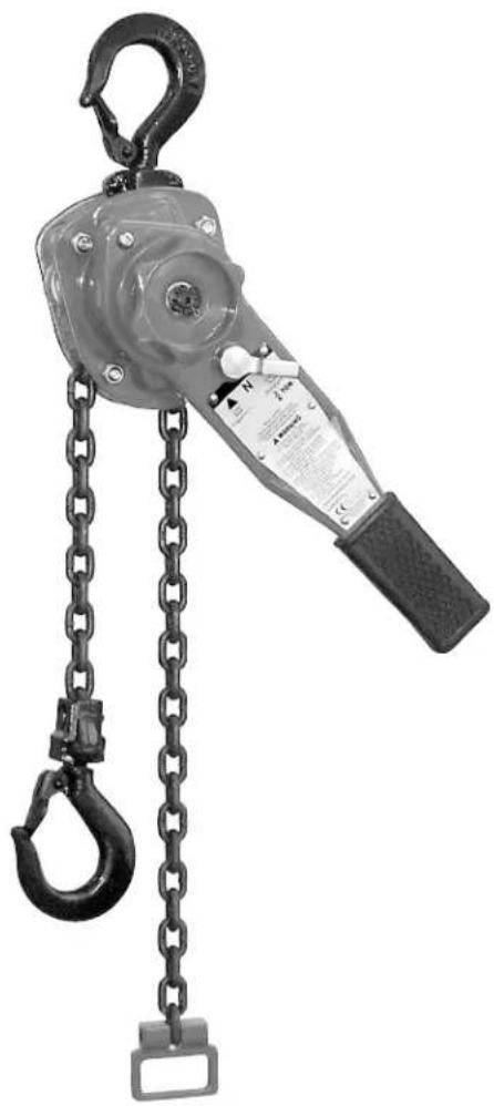
Mechanical hoist with chain and hook components (no visible text or symbols)Catalog No. Rated Load
9682-20 3/4 Ton
9683-20 (750 Kg)
9684-20
9685-20 1½ Ton
9686-20 (1500 Kg)
9687-20
9688-20
9689-20 3 Ton
9690-20 (3000 Kg)
9691-20
A WARNING
Do not use hoist to lift, support or otherwise transport people.
A WARNING
To reduce the risk of injury, do not alter or modify the hoist and only use MILWAUKEE replacement parts. Alterations or modification of hoist and use of non MILWAUKEE parts can lead to dangerous operation and injury.
TO REDUCE THE RISK OF INJURY, USER MUST READ AND UNDERSTAND OPERATORS MANUAL.
SAFETY PRECAUTIONS
Each MILWAUKEELever Operated Chain Hoist is built in accordance with the specifications contained herein and at the time of manufacture complies with our interpretation of applicable sections of *American Society of Mechanical Engineers Code (ASME) B30.21 and the *American National Standards Institute ANSI/ASME HST-3M.
*Copies of this Standard can be obtained from ASME Order Department, 22 Law Drive, Box 2300, Fairfield, NJ 07007-2300, U.S.A.
A WARNING
Improper operation of a hoist can create a potentially hazardous situation which, if not avoided, could result in death or serious injury. To avoid such a potentially hazardous situation, THE OPERATOR SHALL:
- NOT operate a malfunctioning or unusually performing hoist.
- NOT operate the hoist until you have thoroughly read and understood this manual.
- NOT operate a hoist which has been modified without the manufacturer's approval or certification to be in conformity with applicable OSHA regulations.
- NOT lift or pull more than rated load for the hoist.
- NOT use damaged hoist or hoist that is Not working properly.
- NOT use hoist with twisted, kinked, damaged, or worn load chain.
- NOT operate with any lever extension (cheater bar).
- NOT attempt to "free chain" the hoist while a load is applied.
- NOT use the hoist to lift, support, or transport people.
- NOT lift loads over people and make sure all personnel remain clear of supported load.
- NOT attempt to lengthen the load chain or repair damaged load chain.
- Protect the hoists load chain from weld splatter or other damaging contaminants.
- NOT operate a hoist when it is restricted from forming a straight line from hook to hook in the direction of loading.
- NOT use load chain as a sling or wrap load chain around load.
- NOT apply the load to the tip of the hook or to the hook latch.
- NOT apply load unless load chain is properly seated in the chain wheel(s) or sprocket(s).
- NOT apply load if bearing prevents equal loading on all load supporting chains.
- NOT operate beyond the limits of the load chain travel.
- NOT leave load supported by the hoist unattended unless specific precautions have been taken.
- NOT allow the chain or hook to be used as an electrical or welding ground.
- NOT allow the chain or hook to be touched by a live welding electrode.
- NOT remove or obscure the warnings on the hoist.
- NOT operate a hoist which has Not been securely attached to a suitable support.
-
NOT operate a hoist unless load slings or other approved single attachments are properly sized and seated in the hook saddle.
-
NOT lift loads that are Not balanced and the holding action is Not secure, taking up slack carefully.
- NOT operate a hoist unless all persons are and remain clear of the supported load.
- Report malfunctions or unusual performances of a hoist, after it has been shut down until repaired.
- NOT operate a hoist on which the safety placards or decals are missing or illegible.
- Be familiar with operating controls, procedures and warnings.
CAUTION
Improper operation of a hoist can create a potentially hazardous situation which, if not avoided, could result in minor or moderate injury. To avoid such a potentially hazardous situation, THE OPERATOR SHALL:
- Maintain a firm footing or be otherwise secured when operating the hoist.
- Check brake function by tensioning the hoist prior to each lift or pulling operation.
- Use hook latches. Latches are to retain slings, chains, etc. under slack conditions only.
- Make sure the hook latches are closed and not supporting any parts of the load.
- Make sure the load is free to move and will clear all obstructions.
- Avoid swinging the load or hook.
- Avoid lever "fly-back" by keeping a firm grip on the lever until operating stroke is completed and lever is at rest.
- Inspect the hoist regularly, replace damaged or worn parts, and keep appropriate records of maintenance.
- Use MILWAUKEEparts when repairing the unit.
- Lubricate load chain as recommended in this manual.
- NOT operate except with manual power.
- NOT permit more than one operator to pull on lever at the same time. More than one operator is likely to cause hoist overload.
- NOT allow your attention to be diverted from operating the hoist.
- NOT allow the hoist to be subjected to sharp contact with other hoists, structures, or objects through misuse.
- NOT adjust or repair the hoist unless qualified to perform such adjustments or repairs.
The hoists are intended for general industrial use for moving loads within their load ratings. Prior to installation and operation, the user should review the application for abnormal environmental or handling conditions.
SPECIFIC SAFETY RULES - LEVER HOIST
Each MILWAUKEE hand operated lever hoist is built in accordance with the specifications contained herein and at the time of manufacturer complies with our interpretation of applicable sections of the American Society of Mechanical Engineers (ASME) Code B30.21 "Manually Lever Operated Hoists" and the Occupation Safety and Health Act (OSHA). Copies of this standard can be obtained from ASME Order Department, 22 Law Drive, PO Box 2300, Fairfield, NJ 07007-2300, USA.
The safety laws for elevators and for dumbwaiters may specify construction details that are not necessarily incorporated in this hoist. We recommend the use of equipment that meets state and national safety codes. Milwaukee Electric Tool Corporation cannot be responsible for applications other than those for which MILWAUKEE equipment is recommended.
- Read ASME B30.21 safety standard for "Manually Lever Operated Hoists" and this manual thoroughly.
- Do not permit more than one operator to operate lever hoist at one time.
FUNCTIONAL DESCRIPTION
text_image
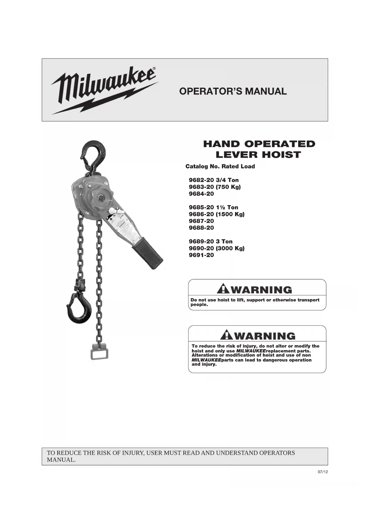
Technical diagram of a manual hoist with numbered parts for identification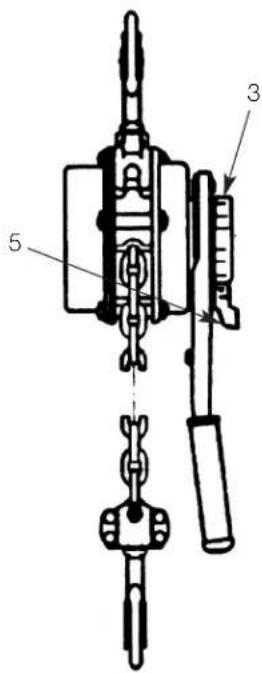
text_image
Technical diagram of a mechanical device with labeled parts 3, 5, and connection points- Upper Hook
- Hoist Frame
- Free Chaining Knob
- Load Chain
- Directional Lever
- Lever
- End Ring
- Lower Hook
- Hook Tip
- Hook Latch
Table 1 - Specifications
| Catalog Capacity LiftNumber Tons (Kg) Ft (M) |
| 9682-20 3/4 (750) 5 (1.5) |
| 9683-20 3/4 (750) 10 (3.0) |
| 9684-20 3/4 (750) 20 (6.1) |
| 9685-20 112 (1,500) 5 (1.5) |
| 9686-20 112 (1,500) 10 (3.0) |
| 9687-20 112 (1,500) 20 (6.1) |
| 9688-20 112 (1,500) 25 (7.6) |
| 9689-20 3 (3,000) 5 (1.5) |
| 9690-20 3 (3,000) 10 (3.0) |
| 9691-20 3 (3,000) 20 (6.1) |
OPERATION
A WARNING
To reduce the risk of injury, carefully check unit for external damage prior to installation. Do not operate a damaged or malfunctioning hoist. Do not operate a hoist with a twisted, kinked, damaged or worn chain. Operating a unit with obvious external damage may cause load to drop resulting in personal injury and/or property damage.
OPERATING INSTRUCTIONS
Before using the MILWAUKEE Lever Hoist, familiarize yourself with all components of this hoist (See Functional Description). Always check the hoist for proper operation before use. Under no circumstances should you operate a malfunctioning hoist.
Figure 1
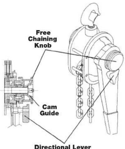
text_image
Free Chaining Knob Cam Guide Directional LeverTest the operation of the hoist before operating at rated capacity.
Operate the hoist with no load and then with a light load of approximately 100 pounds (46Kg) to make sure it operates properly and that the brake holds the load when the lever is released.
WARNING
To reduce the risk of injury, do not lift people or loads over people.
Do not lift more than the rated load.
Do not use load chain as a sling.
FREE CHAINING
In this mode, the load chain can be pulled through the hoist in either direction by hand for quick attachment to the load.
WARNING
To reduce the risk of injury, never pull out or turn the free chaining knob when the hoist is under load. Pulling out or turning the free chaining knob with a load attached will allow the load to release.
To set the hoist to free chaining mode
- Remove any load from the hoist and move the directions lever to the ("N") position.
- Turn the free chaining knob counterclockwise( ) to disengage the brake and pull on either chain until the lower hook is at the desired position.
To reset the hoist for load operation
- To Disengage the free chaining feature, move the directional lever to the load (↑) or unload position (↓). Pull the load chain in either direction to insure the unit is out of the free chaining mode.
A WARNING
To reduce the risk of injury, rig the hoist in a straight line hook to hook and keep the frame free to swivel. If the frame is not free to swivel, the lever pull may break the frame and cause physical injury and/or loss of the load.
The MILWAUKEELever Hoist can be used in any position provided it is rigged to pull in a straight line from hook to hook (See Figure 2). The frame must always be free to swivel on the upper hook.
Figure 2
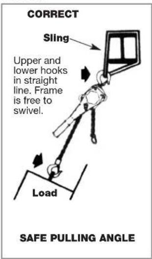
text_image
CORRECT Sling Upper and lower hooks in straight line. Frame is free to swivel. Load SAFE PULLING ANGLE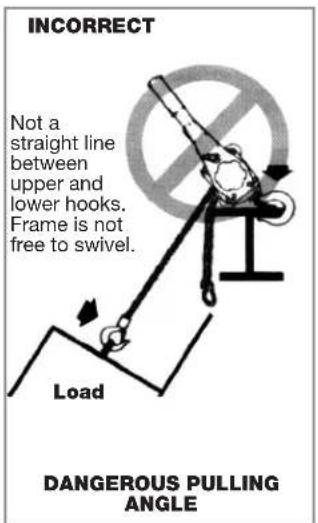
text_image
INCORRECT Not a straight line between upper and lower hooks. Frame is not free to swivel. Load DANGEROUS PULLING ANGLEA WARNING
Do not allow the frame to touch the load or bear on any support when in use. This may cause bending of the hook or frame and cause possible failure.
- Attach the lower hook to the load.
- To take up the slack load chain, follow the instructions under "Free Chaining".
NOTE: The load chain must feed into the chain guide roller properly. A twisted chain may become damaged in the liftwheel and cause chain breakage.
When operating in limited spaces, use attachments or slings to prevent the frame and lever from being obstructed. - To lift or tension a load, set the directional lever to the "LOAD" position and move the lever up and down repeatedly.
- To lower or loosen a load, set the directional lever to the "UNLOAD" position and move the lever up and down repeatedly.
A WARNING
Malfunctioning of unit, rigging slip or loss of footing may cause user to slip and result in injury. To avoid injury, always have a firm and secure footing when using the MILWAUKEE Lever Hoist.
A WARNING
Do not use an extension on the lever. Exceeding the rated lever pull or using an extension to lift or pull a load will overload the hoist.
RECOMMENDED PROCEDURES
- The hoist must be kept clean to assure proper operation. Before use, check to be sure the load chain is clean, that there is no foreign material in the liftwheel area and that the lever operates freely.
- The hoist must always be rigged to lift in a straight line from hook to hook.
a. Rigging can be defined as the process of lifting and moving loads using hoists and other mechanical equipment. Skill acquired through specialized experience and study is essential to safe rigging operations. For rigging information, we recommend consulting a standard text book on the subject.
b. The hoist must always be free to swivel on the upper hook. Under no condition should the hoist frame be allowed to bear on any support when in use as this would cause bending of the hook or frame and damage the unit.
- When preparing to lift or move a load, be sure that the attachments to both hooks are firmly seated in the saddles of the hooks. Avoid off center loading of any kind, especially loading on the tip of the hook. Observe that the chain hangs straight (without twist) from upper hook to lower hook.
-
When lifting, raise the load only enough to clear the floor or the support, and check to be sure brake will load and that attachments to the load are firmly seated. Continue the lift only after you are assured the load is free of all obstructions.
-
Do not load beyond the rated capacity of the hoist. Rated capacity can be achieved with noted force on lever (See Figure 3). Any greater pull is an indication of either an overload or an incorrectly maintained unit.
Figure 3
| Hoist Force on LeverRated Load to Lift Rated LoadTons (Kg) Pounds (Kg) |
| 3/4 (750) 33 (15) |
| 1 12 (1500) 51 (23.1) |
| 3 (3000) 77 (34.9) |
NOTE: Since force on the lever can easily be applied by one person, under no circumstances should more than one person operate the lever hoist. Overloading can cause immediate failure of some load carrying parts or result in damage causing future failure at less than rated capacity. When in doubt, use the next larger capacity MILWAUKEEhoist.
A WARNING
To reduce the risk of injury, do not exceed rated capacity of the hoist. Doing this may cause the load to drop resulting in personal injury and/or property damage.
- Do not wrap load chain around the load or bring the load in contact with the hoist. Doing this will result in the loss of the swivel effect of the hook, which could result in a twisted chain and a jammed liftwheel. The chain could also be damaged at the hook.
- Do not move a load over the heads of other personnel. Warn personnel of your intention to move a load into their area. Stand clear of all loads.
- Do not leave a suspended load unattended.
- Do not take up the load chain to the point where the chain stop or lower hook block becomes jammed against the frame.
- Do not hold load chain while operating the hoist. Should the hoist not operate properly, serious injury may occur.
- Read warnings and instructions on the lever, frame and/or warning tubes before each use.
- Do not run the lower hook block into the hoist frame. Frame and/or chain guide damage may result.
- Do not operate hoist with other than manual power.
- Do not use an extension on the lever.
- Do not use this or any other materials handling equipment for lifting people.
- Do not allow the load to bear against the hook latch. The latch is to prevent detachment of load under slack chain conditions only.
-
When there is a load on the hoist, do not pull or turn the free chaining knob. Doing this will allow the load to be released in a sudden and uncontrolled manner and may cause injury to you and/or property damage.
-
Never operate the hoist when flammable materials or vapors are present. Sharp contact between metal parts can produce sparks that can cause a fire or explosion.
- Do not use the hoist when you are tired, distracted or under the influence of drugs, alcohol or medication, causing reduced control.
WARNING
To reduce the risk of injury, operate hoist using manual power only. Power operation may result in structural damage or premature wear that may cause a part to break and allow the load to fall.
WARNING
To reduce the risk of injury, do not allow the load to bear against the hook latch and/or hook tip. Apply load to hook bowl or saddle only. Allowing the load to bear against the hook latch and/or hook tip can result in loss of load.
MAINTENANCE
Place warning signs and barriers in area when overhead maintenance is taking place.
- After use, set the directional lever to the "UNLOAD" position and move the lever up and down to disengage the brake.
- Remove any dirt or dust from the hoist and chain.
- Lubricate load chain with a light coating of Bar and Chain Oil such as Lubriplate 10-R (Fiske Bros. Refining Co.) or equal lubricant.
- Store the lever hoist in a dry, clean area.
INSPECTION
To maintain continuous and satisfactory operation, a regular inspection procedure must be initiated so that worn or damaged parts can be replaced before they become unsafe. The intervals of inspection must be determined by the individual application and must be based upon the type of service to which the hoist will be subjected. Conduct inspections only when there is no load on hoist. Place warning signs and barriers in area when overhead maintenance is taking place.
The inspection of hoists is divided into two general classifications designated as “frequent” and “periodic”. Frequent inspections are performed daily. Periodic inspections are performed every three (3) months (unless otherwise specified). Periodic inspections will require partial disassembly of the hoist (See “Three Point of Caution for Hoist Disassembly” and “Assembly”).
THREE POINTS OF CAUTION FOR HOIST DISASSEMBLY
Three points of caution are to be observed when disassembling this tool.
-
Loose rollers are used for the liftwheel bearing on the 3/4 ton (750 Kg), 1½ ton (1 500 Kg) and 3 ton (3 000 Kg) units. Do not lose these rollers as they may drop from the unit as various parts are disassembled.
-
The latch is secured to the upper and lower hook by a rivet. To remove the latch, it is necessary to remove the head of the rivet by grinding or drilling. For replacement of the latch refer to assembly instructions.
- The pinion shaft and ratchet hub pawl and shaft are under spring pressure and may fly out of the unit upon disassembly.
FREQUENT INSPECTIONS
These inspections are usually visual examinations by the operator or other designated personnel. The frequent inspections are to be performed daily or before each use and should include the following items:
- All functional operating mechanisms for maladjustment and unusual sounds.
- Hoist braking mechanisms for evidence of slippage.
- Operation of the directional lever for free movement.
- Load chain for lubricant, wear, damaged links or foreign material.
- Proper reeving of load chain (See "Reeving Load Chain" under "Maintenance" section).
- Hooks for damage, cracks, twists, latch engagement and latch operation.
- Hoist support for damage.
Any deficiencies noted are to be corrected before the hoist is returned to service.
PERIODIC INSPECTIONS
These are visual inspections by an appointed and qualified person or service center who makes records of apparent external conditions to provide the basis for a continuing evaluation. The periodic inspections are to be performed every three (3) months unless otherwise specified in this manual.
Due to the construction of the hoist, it will be necessary to partially disassemble the unit to perform the periodic inspections (See "Three Points of Caution for Hoist Disassembly" and "Assembly").
The periodic inspections are to include those items listed under frequent inspections as well as the following:
- Inspect chain and end connections for excessive wear or stretch. ---
- Check for worn, cracked or distorted parts such as lower hook block, upper hook block, upper hook pin, chain guide roller, stripper, side plates, gear cover, gears, bushings, lever, brake cover, free chaining knob, ratchet hub pawl, cam guide, friction hub and lever ratchet hub.
- Inspect for wear on the pawl tips, teeth of the ratchet and pockets of the liftwheel.
- Check for loose or missing bolts, nuts, pins or rivets.
- Inspect brake components for worn, glazed or contaminated friction discs, and scoring of friction hub and ratchet. Replace friction washers if contaminated, glazed or if thickness is less than 0.094 in. (2.4 mm).
- Check for corroded, stretched or broken pawl springs, ratchet hub pawl spring and pinion spring.
-
Check for free movement of the pawls on the pawl studs. Apply a thin coat of lubricant to the pawl studs before reassembling the unit (See "Lubrication" under "Maintenance" section).
-
Check for damage to the hooks, hook retaining nuts, collars, pins, welds or rivets used to secure the retaining members. Dye penetrant, magnetic particle or other suitable crack detecting inspections should be performed at least once a year.
- Check to see if load chain stop is in place and properly secured.
- Check for damage of supporting structure.
- Check for warning labels required by ASME B30.21.
Any deficiencies noted are to be corrected before the hoist is returned to service. External conditions may show the need for more detailed inspection which, in turn, may require the use of nondestructive type testing.
Any parts that are deemed unserviceable are to be replaced with new parts before the unit is returned to service. It is very important that the unserviceable parts be destroyed to prevent possible future use as a repair item.
When the lever hoist is subjected to heavy usage or dusty, gritty, moist or corrosive conditions, shorter time periods must be assigned. Inspection must be made of all parts for unusual wear, corrosion or damage, in addition to those specifically mentioned above.
HOOK INSPECTION AND MAINTENANCE
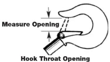
Hooks damaged from chemicals, deformations or cracks, or that have more than a 10 degree twist from the plane of the unbent hook, excessive opening or seat wear must be replaced.
Hooks that are opened and allow the latch to disengage the tip must be replaced.
Any hook that is twisted or has excessive throat opening indicates abuse or overloading of the unit. As a result, other components of the hoist could be damaged.
The chart in Figure 4 should be used to determine when the hook must be replaced. To measure the throat opening, depress the latch against the hook body (See Figure 4).
Figure 4
text_image
Measure Opening Hook Throat OpeningHoist Replace Hook Rated Load When Opening Tones (Kg) is Greater Than:
| 3/4 (750) 1 14 ” (31.8 mm) | |
| 1 12 (1500) 1 | ^2/_a ” (34.9 mm) |
| 3 (3000) 1 | ^23/_32 ” (43.7 mm) |
Check to make sure that the latch is not damaged or bent and that it operates properly with sufficient spring pressure. Spring pressure keeps the latch tight against the tip of the hook and allows the latch to spring back to the tip when released. If the latch does not operate properly, it should be replaced.
CHAIN INSPECTION
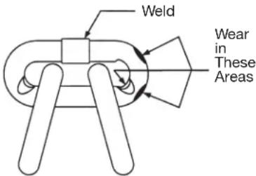
First clean chain with a non-caustic/ non-acid type solvent and make a link by link inspection for nicks, gouges, twisted links, weld spatter, corrosion pits, sitiations (minute parallel lines), cracks in weld areas, wear and stretching. Chain with any one of these defects must be replaced.
Slack the portion of the chain that normally passes over the liftwheel. Examine the interlink area for the point of maximum wear (polishing). Measure and record the stock diameter at this point of the link. Then measure stock diameter in the same area on the link that does not pass over the liftwheel (use the link adjacent to the chain stop for this
text_image
Weld Wear in These AreasFigure 5a - Chain Inspection
purpose). Compare these two measurements. If the stock diameter of the worn link is 0.010 inches (0.254mm), or more, less than the stock diameter of the unworn link, the chain must bereplaced.
text_image
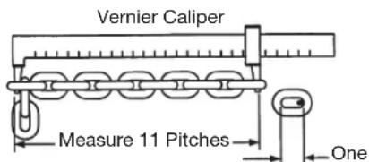
Vernier Caliper Measure 11 Pitches OneFigure 5b - Chain Inspection
Also check chain for stretch using a vernier caliper as shown in Figure 5b. Select an unused, unstretched section of chain (usually at the
loose end) and measure and record the length over 11 chain links (pitches). Measure and record the same length on a worn section of chain.
If the result (amount of stretch and wear) is greater than 0.145 inch (3.7 mm), the chain must be replaced.
Use only a "Knife-Edge" caliper to eliminate possibility of false reading by not measuring full pitch length.
AWARNING
Using other than Milwaukee supplied load chain may cause the chain to jam in the hoist and/or allow the chain to break and the load to drop.
TO AVOID INJURY: Due to size requirements and physical properties, use only Milwaukee supplied load chain in the Milwaukee Lever Hoist.
Note that worn chain can be an indication of worn hoist components. For this reason, the hoist's frame, stripper, and liftwheel should be examined for wear and replaced as necessary when replacing worn chain (See DISASSEMBLY and ASSEMBLY below).
Also, the load chain is specially heat treated and hardened and should never be repaired.
IMPORTANT: Do not use replaced chain for other purposes such as lifting or pulling. Load chain may break suddenly without visual deformation. For this reason, cut replaced chain into short lengths to prevent use after disposal.
LUBRICATION
Before returning chain to service or after replacing a load chain, lubricate liberally with Bar and Chain Oil such as Lubriplate® 10-R (Fiske Bros, Refining Co.) or equivalent, Be sure the lubricant reaches the bearing surfaces between the links. Remove excess lubricant from chain by wiping with a clean, dry cloth.
A WARNING
To reduce the risk of injury, avoid contact with lubricants. Handle and dispose of lubricants only as directed in applicable Material Safety Data Sheets and in accordance with applicable local, state and federal regulations.
A WARNING
To reduce the risk of injury, never use used motor oil as a chain lubricant. Used motor oil contains known carcinogenic materials. Use only Bar and Chain Oil such as Lubriplate ^® 10-R or equivalent as a lubricant for the load chain.
The hoist normally requires no lubrication, except for periodically lubricating the load chain or when the unit is disassembled for periodic inspections, cleaning or repairs.
A WARNING
To reduce the risk of injury, do not use any grease or lubricant on braking surfaces. The brake is designed to operate dry. Using any grease or lubricant on the braking surfaces will cause brake slippage and loss of load control which may result in injury and/or property damage.
The brake is designed to operate dry. Do not use any grease or lubricant on the braking surfaces. When lubricating parts adjacent to the brake, do not use an excessive amount of lubricant which could seep onto the brake surfaces.
When the hoist is disassembled for periodic inspections, check the pawl for free movement and apply a light coat of spray lubricant such as WD-40 (WD-40 Co.) or equivalent, to the pawl stud. When the hoist is disassembled for cleaning or repairs, the following locations should be lubricated using approximately 1 oz. (29.5 ml) per hoist of Extreme Pressure Grease such as Molykote BR-2-S (Dow Corning Corp.) or equivalent:
Gears, liftwheel rollers, upper hook pin, rollers of the liftwheel bearing, inside of chain guide roller, exterior of pinion shaft, surface of ratchet hub pawl, and surface of cam guide and gear cover brushings.
NOTE: To assure extra long life and top performance, be sure to lubricate the various parts of the hoist using the lubricants specified.
ASSEMBLY
Particular attention must be given to the following when assembling the hoist:
Thread the friction hub onto the pinion shaft and assemble the friction discs and the ratchet on the friction hub (See Figure 6).
Figure 6
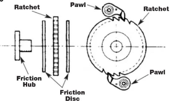
text_image
Ratchet Friction Hub Pawl Friction Disc Ratchet PawlPlace the spring over the friction hub and pinion. Place the brake cover assembly on the frame and thread the lever ratchet onto the pinion shaft. Firmly seat the lever ratchet and secure the brake cover assembly to the frame using the four nuts.
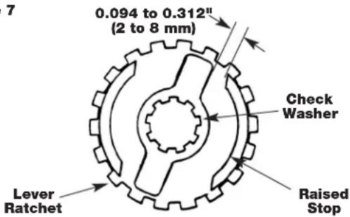
Figure 7
text_image
7 0.094 to 0.312" (2 to 8 mm) Check Washer Lever Ratchet Raised StopPlace the check washer on the pinion shaft so that there is 0.094 to 0.312 inches (2 to 8 mm) between the edge of the check washer and the raised stop on the lever ratchet hub (See Figure 7).
Make sure the directional lever is in the neutral ("N") position and the pawl, spring and shaft are in the lever assembly, attach the lever assembly to the brake cover using the two locknuts, screw and lockwasher. Place the free chaining knob on the lever ratchet hub. Place the spacer over the pinion shaft, thread the brake nut onto the pinion shaft, and firmly tighten the nut. Back off the nut one to two flats and insert the cotter pin. Bend the legs of the cotter pin to secure.
When assembling the latch to the hook, the end of the rivet must be peened over. When peening over rivet, only apply enough force to form a head to retain the pin. Excessive force will deform the latch and make the latch inoperable.
When assembling the gears, they must be orientated with the timing marks aligned (See Figure 8).
Figure 8
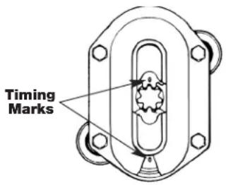
text_image
Timing MarksREEVING LOAD CHAIN
Installing a new length of load chain
To replace the load chain, remove the lower hook block and chain stop from the chain. Move the directional lever to the neutral "N" and pull the old chain out of the hoist. Feed a length of soft wire through one side of the chain guide roller and over the liftwheel until it comes out on the other side of the chain guide roller.
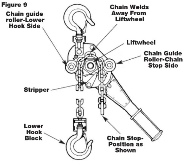
text_image
Figure 9 Chain guide roller-Lower Hook Side Stripper Lower Hook Block Chain Welds Away From Liftwheel Liftwheel Chain Guide Roller-Chain Stop Side Chain Stop-Position as ShownAttach the wire to the end of the new chain. Position the chain so that the first link to enter the chain guide roller will be an upstanding link and the welds on all upstanding links will be away from the liftwheel. Pull on the wire until the chain engages the liftwheel. Turn the free chaining knob, while pulling on the wire, until the chain comes out of the chain guide roller. Pull the chain through and remove the wire. Attach the lower hook block to the chain that is directly below the upper hook. Attach the chain stop to the other end of the chain.
A WARNING
To reduce the risk of injury, feed load chain between liftwheel and chain guide before attaching the warning tubes and end ring. Failure to properly install the load chain may cause the chain to lift out of the liftwheel pockets and allow the load to drop.
TESTING
Prior to initial use, all altered, repaired or used hoists that have not been operated for the previous 12 months should be tested by the user for proper operation. Test the unit without a load and then with a load of 100 pounds (46 Kg) to be sure that the hoist operates properly and that the brake holds the load when the lever is released. Then test with a load of 125% of rated capacity. Hoists in which load sustaining parts have been replaced should be tested with a load of 125% of rated capacity by, or under the direction of, an appointed person and a written report prepared for record purposes.
ACCESSORIES
For a complete listing of accessories refer to your MILWAUKEE Electric Tool catalog. To obtain a catalog, contact your local distributor.
WARNING
To reduce the risk of injury, use only specifically recommended accessories. Others may be hazardous.
LIMITED WARRANTY - USA AND CANADA
Every MILWAUKEE power tool (including cordless product – tool, battery pack(s) - see separate & distinct CORDLESS BATTERY PACK LIMITED WARRANTY statements & battery charger and Work Lights*) is warranted to the original purchaser only to be free from defects in material and workmanship. Subject to certain exceptions, MILWAUKEE will repair or replace any part on an electric power tool which, after examination, is determined by MILWAUKEE to be defective in material or workmanship for a period of five (5) years* after the date of purchase unless otherwise noted. Return of the power tool to a MILWAUKEE factory Service Center location or MILWAUKEE Authorized Service Station, freight prepaid and insured, is required. A copy of the proof of purchase should be included with the return product. This warranty does not apply to damage that MILWAUKEE determines to be from repairs made or attempted by anyone other than MILWAUKEE authorized personnel, misuse, alterations, abuse, normal wear and tear, lack of maintenance, or accidents.
*The warranty period for, Job Site Radios, M12™ Power Port, M18™ Power Source, and Trade Titan™ Industrial Work Carts is one (1) year from the date of purchase. The warranty period for a LED Work Light and LED Upgrade Bulb is a limited LIFETIME warranty to the original purchaser only, if during normal use the LED bulb fails the Work Light or Upgrade Bulb will be replaced free of charge.
*This warranty does not cover Air Nailers & Stapler, Airless Paint Sprayer, Cordless Battery Packs, Gasoline Driven Portable Power Generators, Hand Tools, Hoist – Electric, Lever & Hand Chain, M12™ Heated Jackets, Reconditioned product and Test & Measurement products. There are separate and distinct warranties available for these products.
Warranty Registration is not necessary to obtain the applicable warranty on a MILWAUKEE power tool product. The manufacturing date of the product will be used to determine the warranty period if no proof of purchase is provided at the time warranty service is requested.
ACCEPTANCE OF THE EXCLUSIVE REPAIR AND REPLACEMENT REMEDIES DESCRIBED HEREIN IS A CONDITION OF THE CONTRACT FOR THE PURCHASE OF EVERY MILWAUKEE PRODUCT. IF YOU DO NOT AGREE TO THIS CONDITION, YOU SHOULD NOT PURCHASE THE PRODUCT. IN NO EVENT SHALL MILWAUKEE BE LIABLE FOR ANY INCIDENTAL, SPECIAL, CONSEQUENTIAL OR PUNITIVE DAMAGES, OR FOR ANY COSTS, ATTORNEY FEES, EXPENSES, LOSSES OR DELAYS ALLEGED TO BE AS A CONSEQUENCE OF ANY DAMAGE TO, FAILURE OF, OR DEFECT IN ANY PRODUCT INCLUDING, BUT NOT LIMITED TO, ANY CLAIMS FOR LOSS OF PROFITS. SOME STATES DO NOT ALLOW THE EXCLUSION OR LIMITATION OF INCIDENTAL OR CONSEQUENTIAL DAMAGES, SO THE ABOVE LIMITATION OR EXCLUSION MAY NOT APPLY TO YOU. THIS WARRANTY IS EXCLUSIVE AND IN LIEU OF ALL OTHER EXPRESS WARRANTIES, WRITTEN OR ORAL. TO THE EXTENT PERMITTED BY LAW, MILWAUKEE DISCLAIMS ANY IMPLIED WARRANTIES, INCLUDING WITHOUT LIMITATION ANY IMPLIED WARRANTY OF MERCHANTABILITY OR FITNESS FOR A PARTICULAR USE OR PURPOSE; TO THE EXTENT SUCH DISCLAIMER IS NOT PERMITTED BY LAW, SUCH IMPLIED WARRANTIES ARE LIMITED TO THE DURATION OF THE APPLICABLE EXPRESS WARRANTY AS DESCRIBED ABOVE. SOME STATES DO NOT ALLOW LIMITATIONS ON HOW LONG AN IMPLIED WARRANTY LASTS, SO THE ABOVE LIMITATION MAY NOT APPLY TO YOU, THIS WARRANTY GIVES YOU SPECIFIC LEGAL RIGHTS, AND YOU MAY ALSO HAVE OTHER RIGHTS WHICH VARY FROM STATE TO STATE.
This warranty applies to product sold in the U.S.A. and Canada only.
Please consult the 'Service Center Search' in the Parts & Service section of MILWAUKEE's website www.milwaukeetool.com or call 1.800.SAWDUST (1.800.729.3878) to locate your nearest service facility for warranty and non-warranty service on a MILWAUKEE electric power tool.
LIMITED WARRANTY - MEXICO, CENTRAL AMERICA AND CARIBBEAN
TECHTRONIC INDUSTRIES' warranty is for 5 year since the original purchase date.
This warranty card covers any defect in material and workmanship on this Power Tool.
To make this warranty valid, present this warranty card, sealed/stamped by the distributor or store where you purchased the product, to the Authorized Service Center (ASC). Or, if this card has not been sealed/stamped, present the original proof of purchase to the ASC. Call toll-free 1 800 832 1949 to find the nearest ASC, for service, parts, accessories or components.
Procedure to make this warranty valid
Take the product to the ASC, along with the warranty card sealed/stamped by the distributor or store where you purchased the product, and there any faulty piece or component will be replaced without cost for you. We will cover all freight costs relative with this warranty process.
Exceptions
This warranty is not valid in the following situations:
a) When the product is used in a different manners from the end-user guide or instruction manual.
b) When the conditions of use are not normal.
c) When the product was modified or repaired by people not authorized by TECHTRONIC INDUSTRIES.
Note: If cord set is damaged, it should be replaced by an Authorized Service Center to avoid electric risks.
Model:
Date of Purchase:
Distributor or Store Stamp:
SERVICE AND ATTENTION CENTER
Rafael Buelna No.1
Col. Tezozomoc Mexico, Azcapotzalco D.F.
Ph. 01 800 832 1949
IMPORTED AND COMMERCIALIZED BY:
TECHTRONIC INDUSTRIES MEXICO, S.A. DE C.V.
Av. Santa Fe 481 piso 6, Col. Curz Manca.
CP 05349, Cuajimalpa, D.F.
Milwaukee®
MANUAL del OPERADOR
natural_image
Mechanical hoist with chain and hook components (no visible text or symbols)POLIPASTO MANUAL DE PALANCA
text_image
Technical diagram of a mechanical device with labeled parts 3, 5, and connection pointsnatural_image
Technical diagram of a mechanical component with symmetrical slots and mounting holes (no text or symbols)natural_image
Mechanical hoist with chain and hook attachment (no visible text or symbols)PALANS MANUELS À LEVIER
Charge
Nos. de Cat.
Nominale
9682-20 3/4 Tonne
9683-20 (750 Kg)
9684-20
9685-20 1½ Tonne
9686-20 (1 500 Kg)
9687-20
9688-20
9689-20 3 Tonne
9690-20 (3 000 Kg)
9691-20
AVERTISSEMENT
text_image
Technical diagram of a mechanical device with labeled parts 3, 5, and connection pointsCol. Tezozomoc Mexico, Azcapotzalco D.F.
Ph. 01 800 832 1949
IMPORTÉ ET COMMERCIALISÉ PAR :
TECHTRONIC INDUSTRIES MEXICO, .S.A. DE C.V.
Av. Santa Fe 481 piso 6, Col. Curz Manca.
CP 05349, Cuajimalpa, D.F.
UNITED STATES MILWAUKEE SERVICE
MILWAUKEE prides itself in producing a premium quality product that is Nothing But Heavy Duty®. Your satisfaction with our products is very important to us! If you encounter any problems with the operation of this tool, or you would like to locate the factory Service/Sales Support Branch or authorized service station nearest you, please call...
Additionally, we have a nationwide network of authorized Distributors ready to assist you with your tool and accessory needs. Check your "Yellow Pages" phone directory under "Tools-Electric" for the names & addresses of those nearest you or see the 'Where To Buy' section of our website.
1-800-SAWDUST
(1.800.729.3878)
Monday-Friday
7:00 AM - 6:30 PM
Central Time
or visit our website at
www.milwaukeetool.com
For service information, use the 'Service Center Search' icon found in the 'Parts & Service' section.
Contact our Corporate After Sales Service Technical Support about ...
• Technical Questions
• Service/Repair Questions
- Warranty
call: 1-800-SAWDUST
fax: 1.800.638.9582
email: metproductsupport@milwaukeeetool.com
Register your tool online at www.milwaukeetool.com and...
- receive important notifications regarding your purchase
- ensure that your tool is protected under the warranty
- become a Heavy Duty club member
CANADA SERVICE MILWAUKEE
MILWAUKEE prides itself in producing a premium quality product that is Nothing But Heavy Duty®. Your satisfaction with our products is very important to us! If you encounter any problems with the operation of this tool, or you would like to locate the factory Service/Sales Support Branch or authorized service station nearest you, please call...
1.800.268.4015
Monday – Friday 7:00 – 4:30 CST
fax: 866.285.9049
Milwaukee Electric Tool (Canada) Ltd
140 Fernstaff Court, Unit 4 18129 111 Avenue NW
Vaughan, ON L4K 3L8 Edmonton, AB T5S 2P2
Additionally, we have a nationwide network of authorized Distributors ready to assist you with your tool and accessory needs. Call 1.800.268.4015 to find the names and addresses of the closest retailers or consult "Where to buy" on our Web site www.milwaukeeetool.com
Milwaukee Electric Tool (Canada) Ltd
140 Fernstaff Court, Unit 4 18129 111 Avenue NW
Vaughan, ON L4K 3L8 Edmonton, AB T5S 2P2
MILWAUKEE ELECTRIC TOOL CORPORATION
13135 West Lisbon Road • Brookfield, Wisconsin, U.S.A. 53005