
PP2000 - Programming and display unit IFM - Free user manual and instructions
Find the device manual for free PP2000 IFM in PDF.
| Product type | Programming and display unit for EPS sensors |
| Brand | IFM |
| Model | PP2000 |
| Power supply | 10.8...30 V DC, current consumption <60 mA |
| EPS sensor power supply | U_B - 1.5 V |
| Electrical protection | Short circuits, reverse polarity, overload |
| Housing | Stainless steel 316L, EPDM/X, PC, PBTP, FPM |
| Protection rating | IP 67 |
| Ambient temperature | -25...+80 °C |
| Storage temperature | -40...+100 °C |
| Dimensions (approx.) | Diameter 34 mm, height 100 mm (without connector) |
| Weight (estimate) | 150 g |
| Display | Digital, 4 digits |
| Switching LED | 2 x red (output status) |
| Main functions | Remote indication, remote evaluation, remote programming and adjustment |
| Memories | 1 working memory (nr0) and 3 rewritable non-volatile memories (nr1, nr2, nr3) |
| Response time | OU1 <50 ms, OU2 =0 ms |
| Delay on availability | 1.5 s |
| Maintenance and cleaning | Clean with a dry, non-abrasive cloth |
| Safety | Installation by an electrician, compliance with national and international standards |
| Spare parts and repairability | Mounting flange (ref. E10077) and mounting base available as accessories |
Frequently Asked Questions - PP2000 IFM
User questions about PP2000 IFM
0 question about this device. Answer the ones you know or ask your own.
Ask a new question about this device
Download the instructions for your Programming and display unit in PDF format for free! Find your manual PP2000 - IFM and take your electronic device back in hand. On this page are published all the documents necessary for the use of your device. PP2000 by IFM.
USER MANUAL PP2000 IFM
Operating instructions
Notice utilisateurs
natural_image
Line drawing of a digital kitchen appliance with control panel and buttons (no text or symbols)Inhalt
Controls and visual indication .... page 15
Function and features ...... page 16
Installation ...... page 17
Electrical connection ...... page 17
Programming ...... page 18
Programming generally ...... page 18
Copying and storing sensor parameters . . . . . . . . . . . . . . . . . . . . . . . . . . . . . . . . . . . . . . page 19
Changing stored parameters in PP2000 . . . . . . . . . . . . . . . . . . . . . . . . . . . . . . . . . . . . . . . . . . page 20
Fast programming of sensors .... page 22
Series programming of sensors . . . . . . . . . . . . . . . . . . . . . . . . . . . . . . . . . . . . . . . . . . . . . . page 22
Remote display, remote evaluation, remote parameter setting . . . . . . . . . . . . page 23
Technical data ...... page 25
Scale drawing ...... page 25
Safety instructions
The device shall be supplied from an isolating transformer having a secondary Listed fuse rated as noted in the following table.
| Overcurrent protection | ||
| Control-circuit wire size | Maximum protective device rating Ampere | |
| AWG (mm) | 2) | |
| 26 (0.13) 1 | ||
| 24 (0.20) 2 | ||
| 22 (0.32) 3 | ||
| 20 (0.52) 5 | ||
| 18 (0.82) 7 | ||
| 16 (1.3 ) | 10 | |
The device shall be connected only by using any R/C (CYJV2) cord, having suitable ratings.
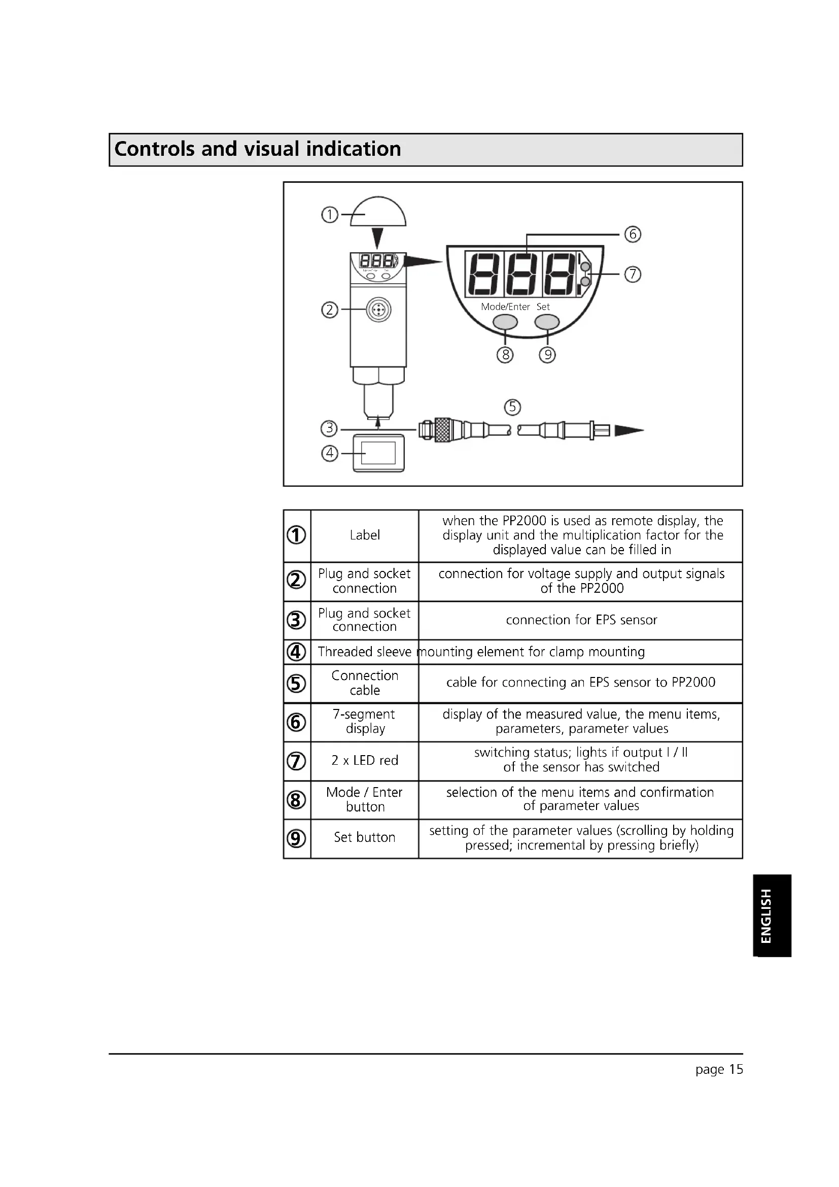
Controls and visual indication
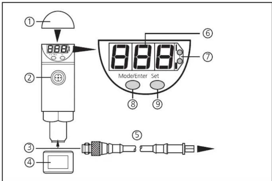
| 1 | Label | when the PP2000 is used as remote display, the display unit and the multiplication factor for the displayed value can be filled in |
| 2 | Plug and socket connection | connection for voltage supply and output signals of the PP2000 |
| 3 | Plug and socket connection | connection for EPS sensor |
| 4 | Threaded sleeve | mounting element for clamp mounting |
| 5 | Connection cable | cable for connecting an EPS sensor to PP2000 |
| 6 | 7-segment display | display of the measured value, the menu items, parameters, parameter values |
| 7 | 2 x LED red | switching status; lights if output I / II of the sensor has switched |
| 8 | Mode / Enter button | selection of the menu items and confirmation of parameter values |
| 9 | Set button | setting of the parameter values (scrolling by holding pressed; incremental by pressing briefly) |
Function and features
flowchart
graph TD
    A["EPS sensor"] -->|exchange of data| B["Electronic Device"]
    style A fill:#f9f,stroke:#333
    style B fill:#bbf,stroke:#333
    note right of A: L+
    note right of B: OU2
    note right of B: OU1
    note right of B: L-
PP2000 is a programming and display unit for EPS sensors (EPS = easily programmable sensor).
- It provides the supply voltage for the sensor,
- detects type, measuring range and current parameters of the sensor,
- reads and displays the current measured value,
• assumes all evaluation functions of the sensor, - permits modification of the current parameters of the sensor
The unit can be connected to the sensor temporarily or permanently.
Operating modes
- Remote display
Indication of the current system pressure (in bar, PSI, MPa or kPa) by an LED display. Indication of the evaluation signals by the switching status LEDs ( page 23).
- Remote evaluation
1 or 2 output signals are provided, according to the sensor and the set output configuration ( page 23).
- Programming / remote programming of the sensor
Parameters can be set before the sensor is mounted and set up or during operation. ( page 23).
Memory
PP2000 has a working memory (indicated as nr0) and a rewriteable read-only memory with 3 memory locations: (nr1, nr2, nr3). This offers the following features:
- Copying and storing sensor parameters
Reads the current parameter values of the sensor and stores them in the memory locations ( page 19).
- Changing stored parameters in PP2000
Loads stored parameters into the working memory, changes and stores them again ( page 20).
- Fast programming / series programming of sensors
Transfers stored parameters to EPS sensors: fast configuration of the sensor before operation / during operation / series programming of several sensors ( page 22).
Installation
There are two options
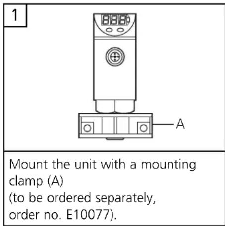
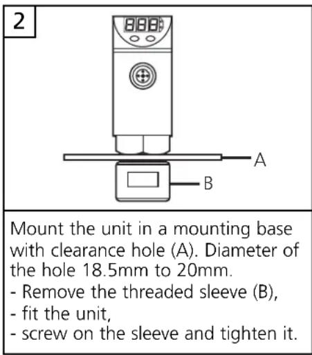
Electrical connection

Use of PP2000 prior to installation of the sensor
Mobile use of the PP2000 after installation of the sensor
Hard-wiring of the PP2000
The unit must only be connected by an electrician.
The national and international regulations for the installation of electrical equipment must be observed.
Voltage supply to EN50178, SELV, PELV
Use a suitable power supply (according to the voltage range of the connected EPS sensor).
Connect PP2000, sensor and plant via the plug and socket connections only!
Do not disconnect these connections while live.
Disconnect power before connecting the unit.
The connection of the outputs during operation depends on the sensor ( operating instructions of the appropriate sensor).
Core colours of ifm sockets:
1 = BN (brown),
2 = WH (white),
3 = BU (blue),
4 = BK (black).
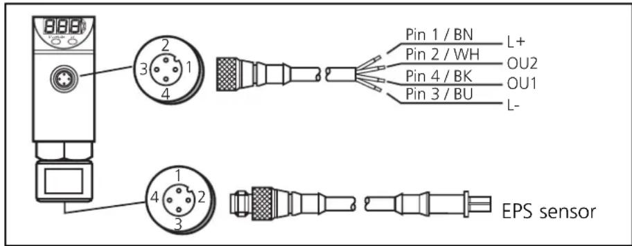
The sensor output signal OU1 is transferred to the PP2000 via the EPS protocol. To avoid malfunction due to interference voltage a shielded cable is recommended in case of a larger distance between sensor and PP2000.
Programming generally
During operation you can use 2 types of menu items:
- Sensor-specific parameters
- Menu items for actions of the PP2000
Sensor-specific parameters
The measuring and evaluation characteristics of the sensor depend on these parameters. For explanations on these parameters please see the operating instructions of the appropriate sensor.
Menu items for actions of the PP2000
| SEL | = select: activates a memory location of PP2000(only active if no sensor is connected) |
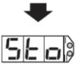
| Sto | = store: stores parameters in PP2000 |
| Snd | = send: transfers parameters from a memory location of PP2000 to the sensor |
These menu items Sto and Snd are included in the sequence of sensor-specific parameters. ( operating instructions of the appropriate sensor).
Programming
Take the following 3 steps for programming
| Press Mode/Enter button: select menu items / parameters1 | |
| 2 | Press Set button: set parameter value, carry out action |
| 3 | Press Mode/Enter button: confirm setting |

The following applies to all settings:
- If no button is pressed for 15s, the program returns to the preceding menu level.
- If modifications of the parameter values have not been confirmed, the previous values remain effective.
- If you change the parameters during operation, the functioning of the plant will be affected. Ensure that plant malfunction is prevented.
Locking / Unlocking
By PP2000 the sensor can be electronically locked to prevent unwanted adjustment of the set parameters: Press (in Run mode) both setting buttons for 10s. As soon as the indication goes out the unit is locked or unlocked. Units are delivered from the factory in the unlocked state. With the unit in the locked state indicated when you try to change parameter values.
Copying and storing sensor parameters
After connection of a sensor the parameters of the sensor are loaded into the working memory of the PP2000.
The parameters of the sensor remain stored in the working memory of the PP2000 even if the voltage supply is interrupted. They are only overwritten if a new sensor is connected.
By storing (Sto), the parameters of the sensor are stored in the selected read-only memory (nr1, nr2 or nr3) of the PP2000.
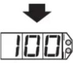
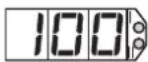
| 1 | Connect the sensor. | 100 | The current sensor data are available in the PP2000. The current measured value is indicated. If the sensor is not connected to the installation, the value "0" is displayed. |
| 2 |  |  | Press the Mode/Enter button several times until the "Sto" is displayed. |
| 3 |  | 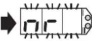 | Press the Set button and keep it pressed. "nr" flashes for 5s, then the available memory locations are displayed one after the othe.* (incremental by pressing briefly or scrolling by holding pressed). |
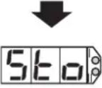
| 4 |  | 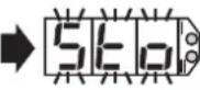 | As soon as the requested memory location is displayed press the Mode/Enter button briefly (= acknowledgement). "Sto" flashes for a short time. When "Sto" no longer flashes, the selected parameters are stored in the read-only memory. After 15s the current measured value is indicated again. |
 | |||
 |
*A read-only memory with three memory locations is available: nr1, nr2, nr3.
Changing stored parameters in the PP2000

No sensor is connected for this operation.
flowchart
graph TD
    A["1"] --> B["2"]
    B --> C["3"]
    C --> D["4"]
    D --> E["5"]
    E --> F["6"]
    F --> G["7"]
    G --> H["8"]
    H --> I["9"]
    I --> J["10"]
    J --> K["11"]
    K --> L["12"]
    L --> M["13"]
    M --> N["14"]
    N --> O["15"]
    O --> P["16"]
    P --> Q["17"]
    Q --> R["18"]
    R --> S["19"]
    S --> T["20"]
    T --> U["21"]
    U --> V["22"]
    V --> W["23"]
    W --> X["24"]
    X --> Y["25"]
    Y --> Z["26"]
Take the following steps:
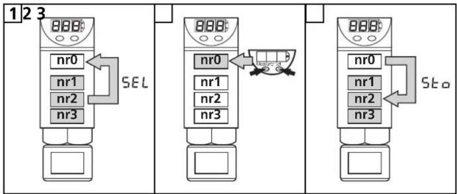
- By selecting the memory location (SEL) you load the respective parameters from a read-only memory (nr1, nr2 or nr3) into the working memory (nr0).
Part 1 / steps 1 - 3
The working storaget contains the last sensor data record read. The data in the working storage are automatically overwritten if
- a new sensor is connected or
- another data record is selected for modification by SEL.
- By programming you change the parameters in the working memory.
Part 2 / steps 4 - 7
- By storing (Sto), you store the new parameters in the selected read-only memory (nr1, nr2 or nr3).
The previous parameters at this location are overwritten.
Part 3 / steps 8 - 10
Part 1:
Load parameters into the working memory SEL
| 1 | Switch on the operating voltage for PP2000 | 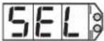 | The menu item SEL (selection of the memory location) is displayed. |
| 2 |  | 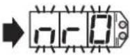 | Press the Set button and keep it pressed."nr0" flashes for 5s,then the available memory locations are displayed one after the other*(incremental by pressing briefly or scrolling by holding pressed). |
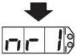 | |||
| 3 | 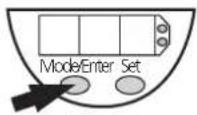 |  | Press the Mode/Enter button briefly (= acknowledgement).The selected parameters are in the working storage and can be modified. |
*A read-only memory with three memory locations is available: nr1, nr2, nr3.
Changing stored parameters in the PP2000
Teil 2: Changing parameters
| 4 |  |  | Press the Mode/Enter button several times until the respective parameter is displayed. |
| 5 | 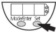 | 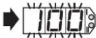 ↓125 ↓125 | Press the Set button and keep it pressed. The current parameter value flashes for 5s,then the value is increased*(incremental by pressing briefly or scrolling by holding pressed). |
| 6 |  |  | Press the Mode/Enter button briefly (= acknowledgement).The parameter is displayed again, the set parameter value is set the working memory. |
| 7 | Change more parameters:Start again with step 4. | Storing parameters:You can store the parameters at any time (→ part 3). | |
*Decrease the value: Let the display of the parameter value move to the maximum setting value. Then the cycle starts again at the minimum setting value.
Part 3: Storing changed parameters 560
| 8 |  |  | Press the Mode/Enter button several times until the “Sto” is displayed. |
| 9 | 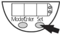 | 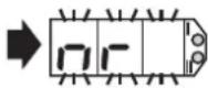 | Press the Set button and keep it pressed. “nr” flashes for 5s, then the available memory locations are displayed one after the other* (incremental by pressing briefly or scrolling by holding pressed). |
| 10 |  | 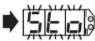 | As soon as the requested memory location is displayed press the Mode/Enter button briefly (= acknowledgement). “Sto” flashes for a short time. When “Sto” no longer flashes, the selected parameters are stored in the read-only memory. After 15s “SEL” is indicated. |
 | |||
 |
*A read-only memory with three memory locations is available: nr1, nr2, nr3. **Cancel:If you do not want to store the data record, wait for 15s. The unit quits the menu item and displays "SEL" again.
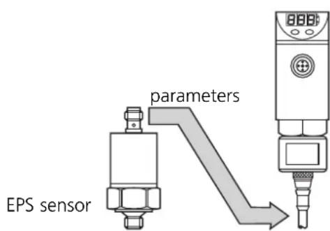
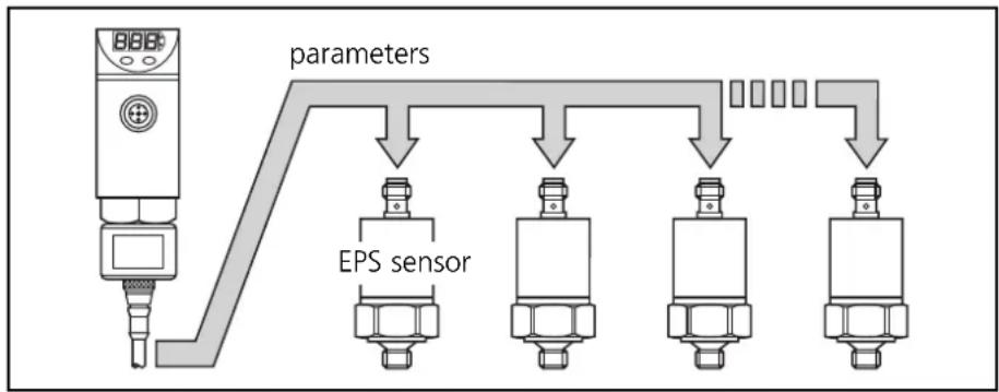
Fast programming / series programming of sensors
flowchart
graph TD
    A["BBPS"] --> B["parameters"]
    B --> C["EPS sensor"]
    C --> D["..."]
    D --> E["..."]
    E --> F["..."]
    F --> G["..."]
5nd
By sending (Snd), selected parameters are stored in a sensor. The new parameters are effective immediately.
| 1 |  ➡ ➡  | Press the Mode/Enter button several times until the "Snd" is displayed. |
| 2 |  ➡ ➡ 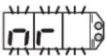 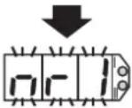 | Press the Set button and keep it pressed. "nr" flashes for 5s, then the available memory locations are displayed (flashing) one after the other* (incremental by pressing briefly or scrolling by holding pressed). |
| 3 |  ➡ ➡ 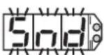 — — 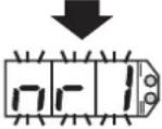 | As soon as the requested memory location is displayed press the Mode/Enter button briefly. "Snd" flashes for 1 second, then again the active memory location. If no error messages have been displayed, the parameters were transmitted successfully. |
| 4 | Configure other sensors: Connect a new sensor and press the Mode/Enter button briefly. The active parameters can be transferred as often as you like. | Finish sending: 1. Press the Set button until "End" is displayed. 2. Press the Mode/Enter button briefly. |
*A read-only memory with three memory locations is available: nr1, nr2, nr3.
Error messages
| SEE | = sensor type error (the parameters are not suited for the type/measuring range of the sensor) |
| IOE | IOE = input output error (the data transfer was unsuccessful) |
The menu Snd is only used to transfer the parameters stored in the memory locations of the read-only memory.
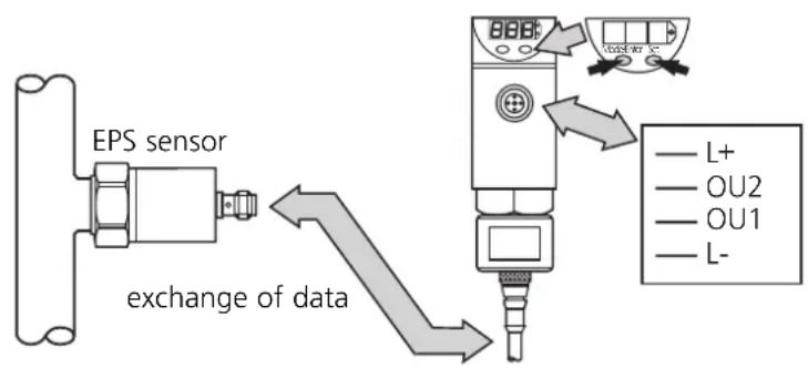
Remote display, remote evaluation, remote parameter setting
flowchart
graph TD
    A["EPS sensor"] -->|exchange of data| B["Device"]
    B --> C["L+"]
    B --> D["OU2"]
    B --> E["OU1"]
    B --> F["L-"]
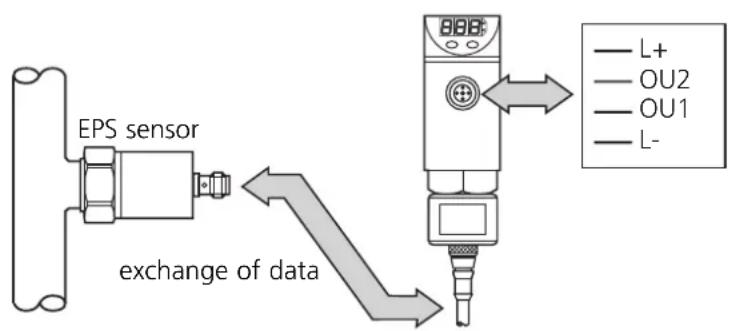
If the sensor is connected to PP2000
- it is supplied with operating voltage by this unit,
- it continuously transfers its data to this unit (measured values, signals transferred to the evaluation electronics and parameter settings).
Modifications to any parameter values are stored in the sensor after confirmation. They are effective immediately.
Remote display / Measured value
Connect the sensor.
The current sensor data are available in the PP2000. The current measured value is indicated.
Remote display / Parameter values
(checks the set parameter values of the sensor)
| 1 | 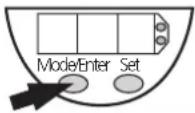 | 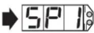 | Press the Mode/Enter button several times until the respective parameter is displayed. |
| 2 |  | 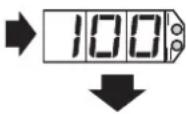 | Press the Set button briefly. The current parameter value is dispayed, then the parameter is displayed again. |
| 3 | Read other parameters: Start again with step 1. | Finish reading: Wait for 15s or press the Mode/Enter button until the current measured value is indicated again. | |
The output signals of the sensor are provided at the output of the PP2000.
- The output signal OU2 is directly transferred to OU2 of the PP2000.
- The output signal OU1 is transferred to the PP2000 via the EPS protocol and is available at OU1.
For the wiring diagram refer to the operating instructions of the sensor.
Remote display, remote evaluation, remote parameter setting
Remote parameter setting
Changing sensor parameters using the programming menu. For information on the parameters to be set see the operating instructions of the respective sensor..
| 1 | 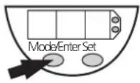 |  | Press the Mode/Enter button several times until the respective parameter is displayed. |
| 2 |  | 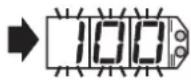 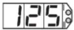 | the Set button and keep it pressed. The current parameter value flashes for 5s,then the value is increased*(incremental by pressing briefly or scrolling by holding pressed). |
| 3 |  |  | Press the Mode/Enter button briefly (= acknowledgement).The parameter is displayed again, the set parameter value becomes effective. |
| 4 | Change more parameters:Start again with step 1. | Finish programming:Wait for 15s or press the Mode/Enter button until the current measured value is indicated again.. | |
*Decrease the value: Let the display of the parameter value move to the maximum setting value. Then the cycle starts again at the minimum setting value.
Select the display unit (bar, PSI, Pa) before setting the switch points (SPx, rPx) or the limits for the analog output signal (ASP, AEP). This avoids rounding errors generated internally during the conversion of the units and enables exact setting of the values.
Every modification of a parameter is stored in the sensor directly after confirmation (step 3) and is effective immediately. If all requested parameters are set, programming is finished.
Do not activate the menu "Snd"
The menu Snd must not be activated. Parameters transferred to the sensor via Snd would overwrite the parameter values set with the programming menu.
Storing possible with Sto
The parameter values set with the programming menu are in the sensor and the working memory of the PP2000. They can therefore be stored permanently with the menu Sto ( page 19).

If you change the parameters during operation, the functioning of the plant will be affected. Ensure that plant malfunction is prevented.
Technical data
| Operating voltage [V]....10.8 ... 30 DCCurrent rating [mA].....250Short-circuit protection,reverse polarity protection / overload protectionVoltage drop [V].....< 2Current consumption [mA]....< 60Voltage supply for EPS sensors [V].....UB - 1.5V |
| Power-on delay time [s]....1.5Response time for the transmissionof the sensor signal [ms]....OU1 < 50 / OU2 = 0 |
| Housing material stainless steel (316S12); EPDM/X (Santoprene);PC (Copolymer); PBTP (Pocan); FPM (Viton)Protection....IP 67Protection class....III (SELV; PELV)Insulation resistance [MΩ]....> 100 (500 V DC)Shock resistance [g]....50 (DIN / IEC 68-2-27, 11ms)Vibration resistance [g]....20 (DIN / IEC 68-2-6, 10 - 2000 Hz)Operating temperature [°C]....-25 ... +80Storage temperature [°C]....-40 ... +100EMCIEC 1000/4/2 ESD:....4 / 8 KVIEC 1000/4/3 HF radiated:....10 V/mIEC 1000/4/4 Burst:....2 KVIEC 1000/4/6 HF conducted:....10 V |
Scale drawing
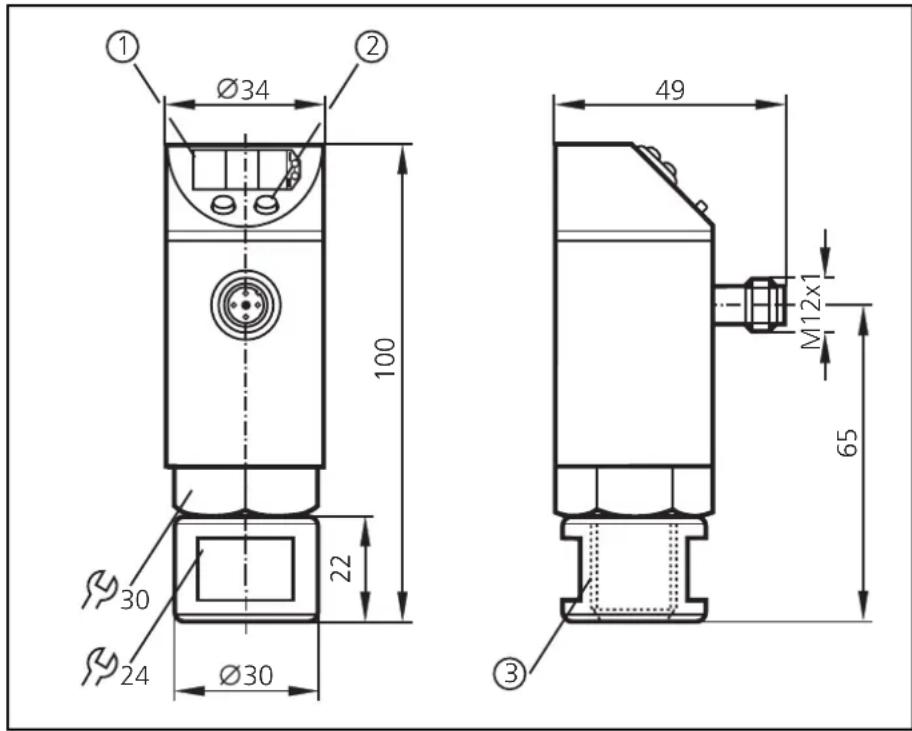
1 = display
2 = programming button
3 = thread M18 x 2.5
Contenu
- Inhalt
- Safety instructions
- Controls and visual indication
- Function and features
- Operating modes
- - Remote display
- - Remote evaluation
- - Programming / remote programming of the sensor
- Memory
- - Copying and storing sensor parameters
- - Changing stored parameters in PP2000
- - Fast programming / series programming of sensors
- Installation
- There are two options
- Electrical connection
- Programming generally
- Sensor-specific parameters
- Menu items for actions of the PP2000
- Programming
- Locking / Unlocking
- Copying and storing sensor parameters
- Changing stored parameters in the PP2000
- Part 1:
- Fast programming / series programming of sensors
- 5nd
- Error messages
- Remote display, remote evaluation, remote parameter setting
- Remote display / Measured value
- Remote display / Parameter values
- Remote parameter setting
- Do not activate the menu "Snd"
- Storing possible with Sto
- Technical data
- Scale drawing
- Contenu
Brand : IFM
Model : PP2000
Category : Programming and display unit