
DC0103 - Industrial electronic system IFM - Free user manual and instructions
Find the device manual for free DC0103 IFM in PDF.
| Product type | Pulse evaluation system |
| Brand | IFM |
| Model | DC0103 |
| Supply voltage | 12V DC or 24V DC |
| Input | Pulses from a proximity detector (PNP) |
| Switching output | 1 potential-free changeover relay, max. current 8 A |
| Setting range | 30 ... 25,000 pulses/min |
| Accuracy | Approximately 1% of the programmed value |
| Display | Green LED (supply voltage), yellow LED (input pulses), green LED (relay status), 2 red LEDs (programming) |
| Housing | Insulating material with transparent front, IP65 |
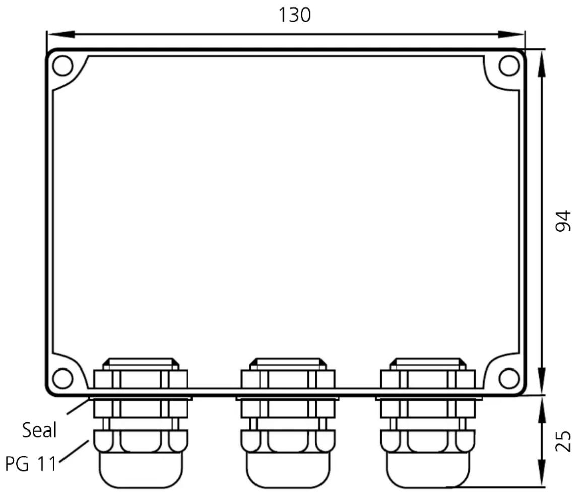
| Dimensions (L x W x D) | Approx. 130 x 94 x 60 mm |
| Weight | Approx. 200 g |
| Connection | Screw terminals (max. 4 mm²) |
| Ambient temperature | -20°C ... +60°C |
| Main functions | Rotation speed monitoring, self-teaching, setting of min/max switching points |
| Maintenance and cleaning | No special maintenance required, check function regularly |
| Safety | Do not touch internal components (ESD sensitive) |
| Accessories | External rotation speed display (ref. E80103) |
Frequently Asked Questions - DC0103 IFM
User questions about DC0103 IFM
0 question about this device. Answer the ones you know or ask your own.
Ask a new question about this device
Download the instructions for your Industrial electronic system in PDF format for free! Find your manual DC0103 - IFM and take your electronic device back in hand. On this page are published all the documents necessary for the use of your device. DC0103 by IFM.
USER MANUAL DC0103 IFM
Function and features
The DC0103 monitors rotational speeds (mainly with regard to under-speed).
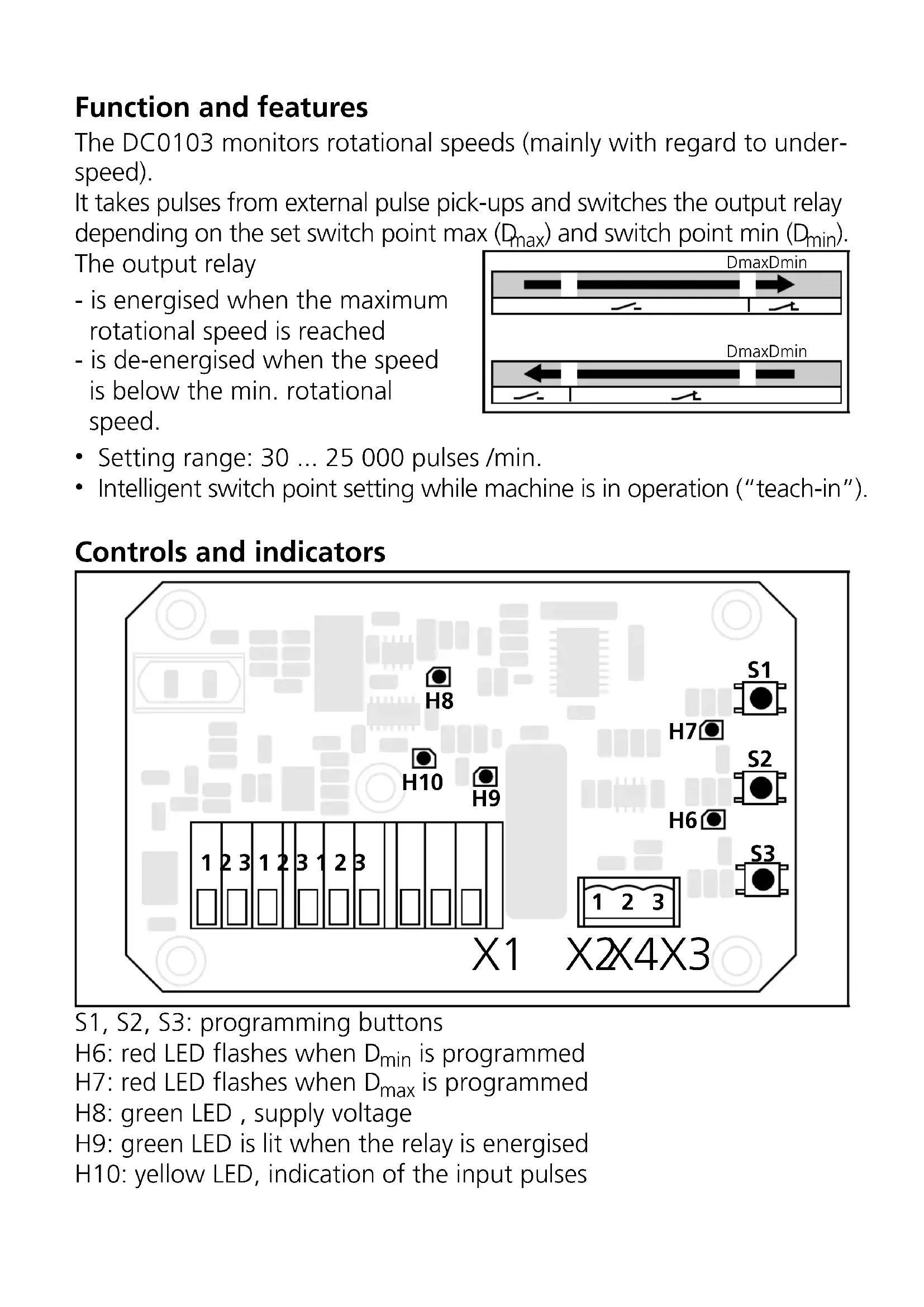
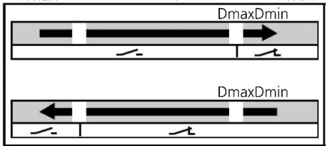
It takes pulses from external pulse pick-ups and switches the output relay depending on the set switch point max ( D_max ) and switch point min ( D_min ).
The output relay
- is energised when the maximum rotational speed is reached
- is de-energised when the speed is below the min. rotational speed.
- Setting range: 30 ... 25 000 pulses /min.
- Intelligent switch point setting while machine is in operation ("teach-in").
Controls and indicators
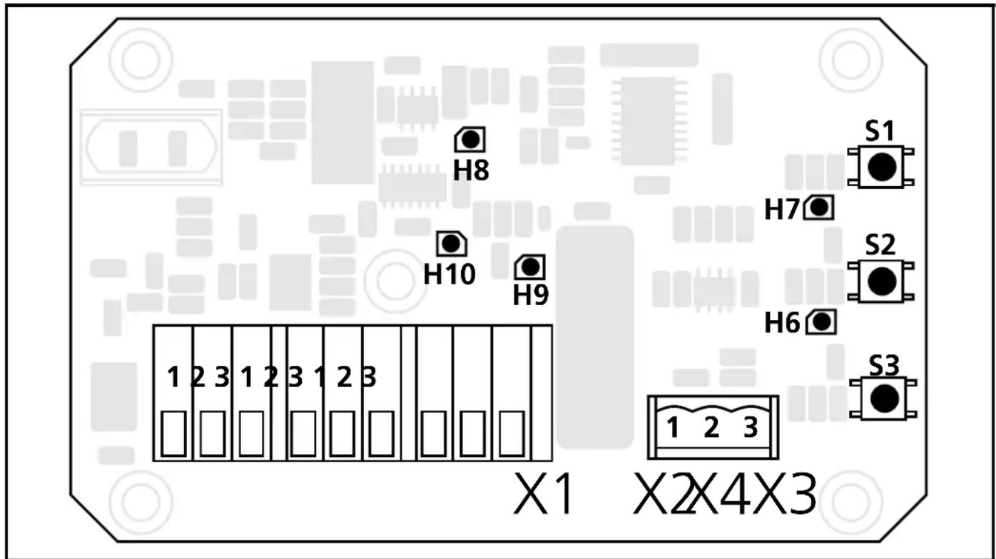
S1, S2, S3: programming buttons
H6: red LED flashes when D_min is programmed
H7: red LED flashes when D_max is programmed
H8: green LED, supply voltage
H9: green LED is lit when the relay is energised
H10: yellow LED, indication of the input pulses
Mounting
Mount the unit with screws on a mounting base.
Mounting of the pulse pick-up
For optimum functioning the following mounting dimensions should be adhered to:
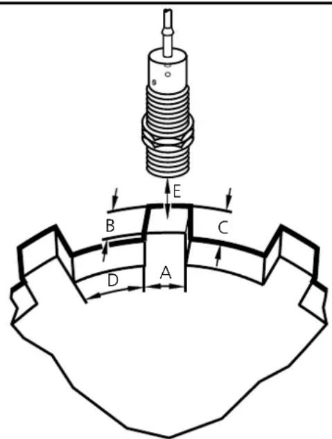
A } at least diameter of the speed monitor
B C
D at least 2 x A
E 1/2 × S_n
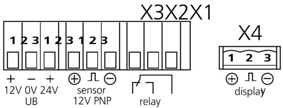
Electrical connection

Disconnect power.
Open transparent front panel and connect the unit as follows:

The unit is equipped with integrated C-Mos components. They can be destroyed by electrostatic discharge (ESD). Thus no components except for push-buttons and connection terminals may be touched.
Setting
| 1 | Set the maximum rotational speed of the machine and keep it constant | LED H10 flashes in time to the input pulses | ||
| 2 | 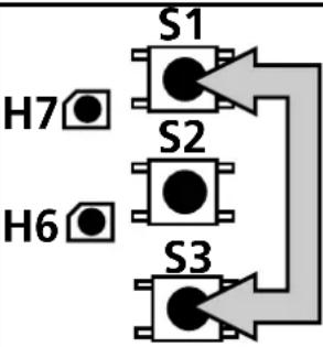 | Press the push-buttons and hold them until LED H7 flashes | 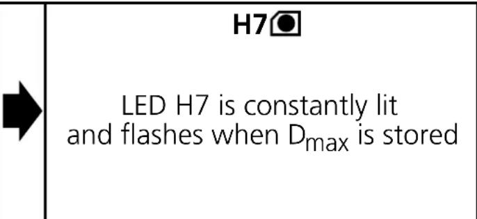 | |
| 3 | Set the minimum rotational speed of the machine and keep it constant | LED H10 flashes in time to the input pulses | ||
| 4 | Press the push-buttons and hold them until LED H6 flashes | H6●LED H6 is constantly lit and flashes when Dminis stored | ||
| 4 | 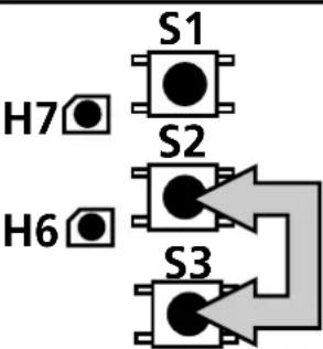 | Press the push-buttons and hold them until LED H6 flashes | H6●LED H6 is constantly lit and flashes when Dmin is stored |
| H6 | |
| LED H6 is constantly lit and flashes when Dmin is stored |

D_max must always be greater than D_min !
Operation
Check the safe functioning of the unit.
If operation is correct no special measures need to be taken nor any measures for maintenance and upkeep.
For operation and maintenance of the pulse pick-ups the manufacturer's instructions must be observed.
Accessories
Rotational speed display for service and operation.
You can connect an external display on the terminal block X4 to display the actual rotational speed.
Order no.: E80103
Technical Data
| Nominal voltage | From 12V DC or 24V DC on-board system with diesel generator set running |
| Inputs power supply 12V/24V DC | via 3 screw terminals;(without load-dump protection)pulses proportional to the rotational speed from a proximity switch;including connection terminals for sensor supply |
| Output | 1 floating changeover contact,current rating 8 A |
| Display green LED : operating voltage | yellow LED : input pulsesgreen LED : relay status2 red LEDs : programming |
| Logic microcontroller with EEPROM,programmed in Assembler | |
| Accuracy approx. 1% of programmed rotational speed value | |
| Housing insulating material with transparent cover,approx. 130 x 94mm base, approx. 60mm highwith 3 cable glands PG 11; protection rating IP 65 | |
| Connection screw terminals up to 4mm | ^2 on PCB |
| Operating temperature -20°C ... +60°C | |
Brand : IFM
Model : DC0103
Category : Industrial electronic system