
LR7022 - Detector IFM - Free user manual and instructions
Find the device manual for free LR7022 IFM in PDF.

| Product Type | Electronic level sensor (guided microwave radar) |
| Model | LR7022 |
| Brand | IFM |
| Probe length | 240 mm (can be shortened to 150 mm minimum) |
| Housing diameter | 50 mm |
| Process connection | G 3/4 |
| Power supply | 18…30 V DC (SELV/PELV according to EN50178) |
| Power consumption | < 80 mA |
| Outputs | 2 switching outputs (200 mA each, protected against short circuit and reverse polarity) |
| Display unit | cm or inch (selectable) |
| Measuring range (level) | 1.5…20.0 cm (with original probe, OFS=0) |
| Threshold accuracy | ±5 % of final value of measuring range |
| Repeatability | ±2 % of final value of measuring range |
| Fluid temperature | 0…80 °C |
| Ambient temperature | 0…60 °C |
| Maximum tank pressure | 0.5 bar |
| Materials (housing and seal) | INOX 304, FKM, NBR, PBT, PC, PEI, TPE, PTFE |
| Materials in contact with fluid | INOX 303, PTFE, NBR |
| Protection rating | IP 67 |
| Maintenance and cleaning | Clean the probe and process connection. Check the mounting and minimum distances in case of Err1 error. |
| Safety | Installation by an electrician. Observe national and international standards. SELV/PELV power supply. Compliant with EN 50081-2 (class A). |
| Spare parts and reparability | Replacement probes available (E43203 240mm, E43204 450mm, E43205 700mm). Screw-on flange as accessory. In case of electronic fault (Err0), the device must be replaced. |
Frequently Asked Questions - LR7022 IFM
User questions about LR7022 IFM
0 question about this device. Answer the ones you know or ask your own.
Ask a new question about this device
Download the instructions for your Detector in PDF format for free! Find your manual LR7022 - IFM and take your electronic device back in hand. On this page are published all the documents necessary for the use of your device. LR7022 by IFM.
USER MANUAL LR7022 IFM
Operating instructions
Electronic level sensor
natural_image
Line drawing of a handheld electronic device with a circular button and handle (no text or symbols)Inhalt
natural_image
Diagram of a vertical device with directional arrows indicating flow or movement, no text or symbols present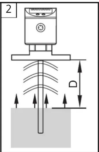
Funktionsübersicht
natural_image
Two technical diagrams showing a device with labeled component D, one with a crosshair and arrow indicator, the other with a crossed line (no text or symbols)Zu 3:
line
| Signal | Time (t) | Value | |--------|----------|-------| | SP1 | 0 | ~100 | | rP1 | 0 | ~80 | | SP2 | 0 | ~90 | | rP2 | 0 | ~70 | | OUT1 | 1 | 1 | | Hnc | 1 | 0 | | OUT2 | 1 | 1 | | Hno | 1 | 0 |Function and features 25
Functional overview 25
Mounting 27
Electrical connection 32
Programming 33
Controls and indicating elements 34
Menu structure 35
Installation and set-up / Operation 40
Technical data 41
Applications 42
Scale drawing 45
Important notes for the user of these instructions
- These operating instructions are a part of the product. Carefully read them before using the product.
- Keep the operating instructions for later use.
- Pass the operating instructions on to future owners or users of the product.
- Whenever you receive a supplement to these operating instructions enclose it to them.
Safety instructions
- The unit must be connected by a suitably qualified electrician.
- The national and international regulations for the installation of electrical equipment must be observed.
• Voltage supply according to EN50178, SELV, PELV. - The unit complies with the standard EN 50081-2 and is a class A product. The radiated energy of the microwaves is, for example, much below that of mobile phones. According to the current state of science the operation of the unit can be classified to be harmless to human health.
- Improper use or non-intended use may lead to malfunctions of the unit or to unwanted effects in your application. That is why installation, electrical connection, set-up, operation and maintenance of the unit must only be carried out by qualified personnel authorised by the machine operator.
Function and features
Applications
LR70 is a compact level sensor for the detection of liquids. The unit was specially designed to meet the requirements of machine tool building. It is specially suited for monitoring coolant emulsions as well as aqueous cleaning agents in part cleaning systems.
Restriction of the application area
- Only use the unit in metal tanks.
Not suited for plastic tank covers.
- The unit is not suitable for oils, fats, granulates, bulk materials, acids, alkalis; it is not suitable for food and electroplating applications.
- Foam, separate layers (e.g. oil on water), highly absorbing or bubbling surfaces can lead to incorrect measurements or signal loss. Check the function by an application test.
In case of signal loss, the unit displays "Err1" and switches the outputs to a defined state →page 41, output response).
Functional overview
Measuring principle
The unit operates to the principle of guided wave radar: It measures the
level using electromagnetic pulses in the nanosecond range.
The pulses are transmitted by the sensor head and guided along the probe (fig. 1). When they hit the medium to be detected they are reflected and guided back to the sensor (fig. 2). The time between transmitting and receiving the pulse directly relates to the travelled distance and the current level.
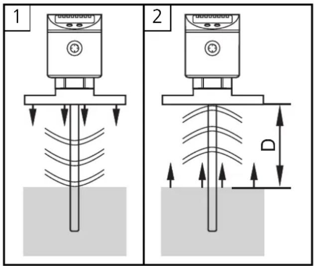
The reference for distance measurement is the lower edge of the thread.
Functional overview
- The unit displays the current level and signals via two switching outputs that the set limits have been reached or that the level is below the set limit. The setpoint and reset point values and the switching function of the outputs can be set via the user menu. For each of the two switching outputs a switch-off delay (max. 5 s) can be set (e.g. for specially long pump cycles).
- The unit can be installed in tanks of different sizes. 3 probe lengths are available. To adapt to the tank height, it is also possible to shorten the probe. The unit can be set to the new probe length via the user menu.
- The zone between tank bottom and lower edge of the measuring probe can be entered as offset value (OFS). Thus display and switch points refer to the real level.
- The display unit can be set: cm or inch..
- The unit can be reset to the factory settings.
- The response of the outputs in case of a fault is adjustable. If a fault is detected or if the signal quality is below a minimum value, the outputs pass into the safe state (→page 37, parameters FOU1 and FOU2).
- Housing rotatable by 360^ for orientation after mounting.
- Probe rotatable by 360^ for easier mounting / removal of the probe.

To ensure the unit functions correctly, certain installation conditions must be adhered to.
Read the following chapter (mounting) carefully and follow the instructions.
Mounting
There are 3 mounting options:
- Screw in a G ^3/4 process connection in the tank lid.
- Installation in the tank lid using a flange plate (e.g. for tanks with thin walls).
- Installation in an open tank using a fixture.
ATTENTION: In all cases the unit needs a metal surface to transfer the measured signals (transfer plate).
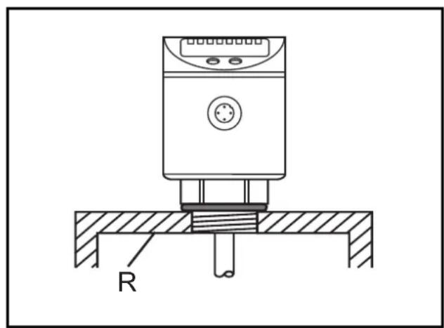
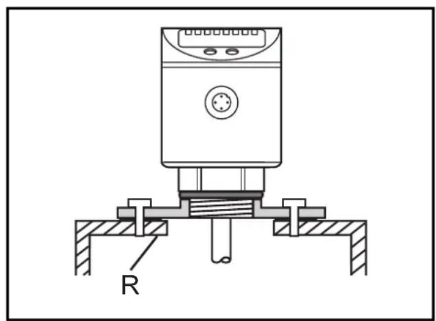
On 1 and 2:
For installation in closed metal tanks, the metal lid serves as a transfer plate (R).
natural_image
Technical line drawing of a mechanical device with a base and mounting base, labeled 'R' (no text or symbols beyond label)The lower edge of the thread should be flush with the mounting environment. Use seals or washers (D) to reach the required height.
When using the ifm flange plates ( page 31) flush installation is ensured.
natural_image
Technical diagram of a mechanical device with labeled component R (no text or symbols beyond label)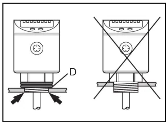
natural_image
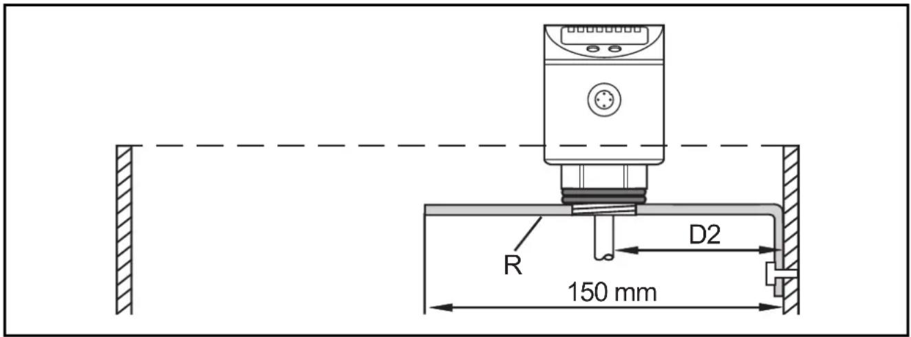
Technical diagram showing two identical electrical components with labeled connection points and a cross symbol (no text or labels present)On 3:
For installation in open metal tanks, the unit must be mounted using a metal fixture. It serves as a transfer plate (R). Minimum size: 150 x 150 mm for a square fixture, 150 mm diameter for a circular fixture. If possible, mount the unit in the middle of the fixture. The distance D2 must be min. 40 mm.
Installation location / installation environment
- The following minimum distances between the probe and tank walls, objects in the tank (B), tank bottom and other level sensors must be adhered to:
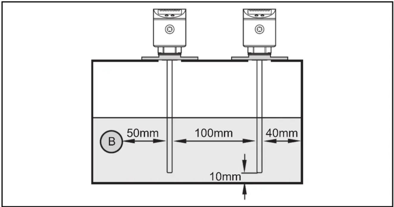
- For tank walls which are not straight, steps, supports or other structures in the tank a distance of 50 mm to the tank wall must be adhered to.
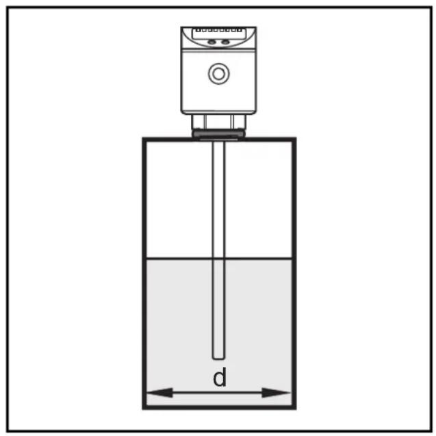
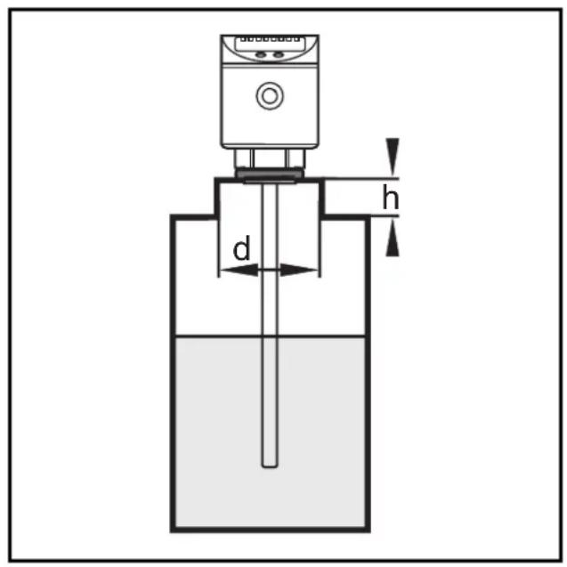
- For installation in pipes the inside pipe diameter (d) must be min. 100 mm. Only use metal pipes.
- For installation in connection pieces the connection piece diameter (d) must be min. 50 mm. The height of the connection piece (h) must not exceed 40 mm.
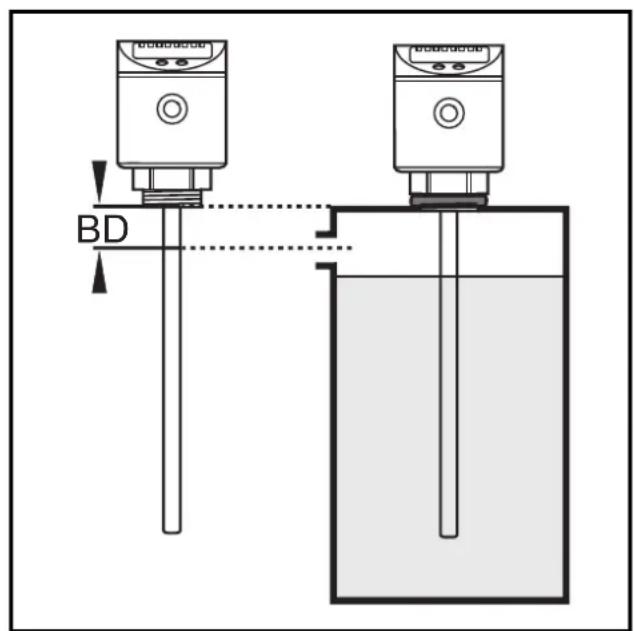
- The maximum level must not exceed the blocking distance (BD = 40 mm). If it is exceeded by more than 10 mm, measurement errors and error messages can occur. Arrange for a spout to avoid this problem.
Adaptation of the probe
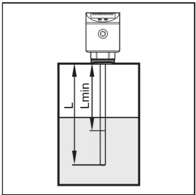
The sensors are supplied with probes in different lengths (L):
LR7022: L = 240 mm
LR7023: L = 450 mm
LR7024: L = 700 mm
The probes can be shortened to adapt to different tank heights. The minimum permissible probe length Lmin is 150 mm.
Proceed as follows:
- Mark the desired length (L).
- Unscrew the probe from the unit.
- Shorten the probe. Ensure that the probe length is not below the minimum permissible length (15 cm / 6 inch).
- Remove all burrs and sharp edges.
- Screw the probe to the unit. Recommended tightening torque: 4 Nm.
- Set the new probe length during set-up ( page 36, menu point: LEnG).
Notes:
Probes are also available as accessories: E43203 (240 mm), E43204 (450 mm), E43205 (700 mm).
Every LR70 type sensor can be combined with any of the indicated probes.
For ease of mounting and removal the probe can be rotated with respect to the thread (process connection) without restriction. Even if rotated several times by 360^ there is no risk of damage to the sensor.
Installation of the sensor using a flange plate
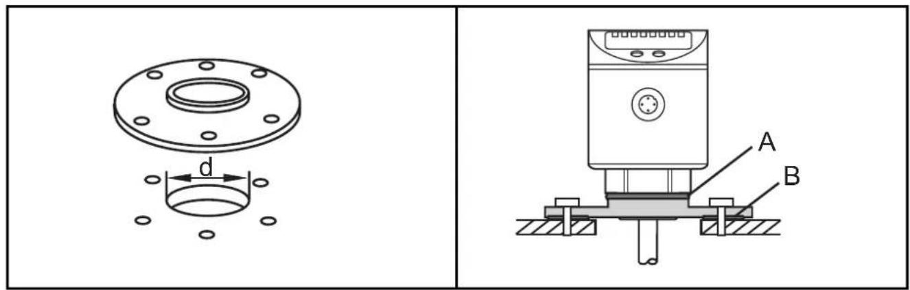
- For installation of the unit you need a bore hole in the tank lid. The bore hole must have a minimum diameter (d) to enable sufficient transfer of the measured signal to the probe. The diameter depends on the wall thickness of the tank lid:
| Wall thickness [mm] 1...5 5...8 8...11 | ||
| Bore hole diameter [mm] 30 40 55 |
- The flange plate is mounted with the flat surface showing to the tank and fixed with screws. Place the sensor seal (A) and the adapter seal (B).
- After mounting, the sensor housing can be aligned. It can be rotated with respect to the thread (process connection) without restriction. Even if rotated several times by 360^ there is no risk of damage to the sensor.
The following flange plates are available as accessories:
Flange plate 73 - 90 / G ^3/4 , aluminium .... order no. E43201
Flange plate 65 - 80 / G ^3/4 , aluminium .... order no. E43202
They are suitable for a maximum tank pressure of 0.5 bar.
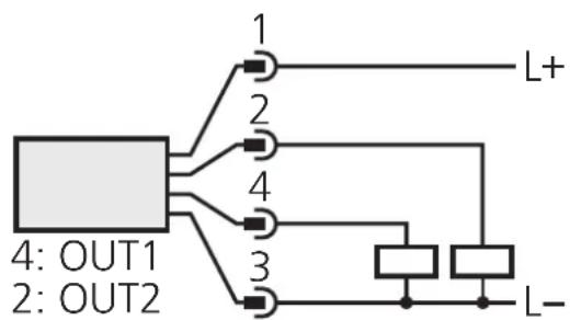
Electrical connection
The unit must be connected by a suitably qualified electrician. The national and international regulations for the installation of electrical equipment must be observed.
Voltage supply according to EN50178, SELV, PELV.
Disconnect power before connecting the unit as follows:
flowchart
graph TD
    A["4: OUT1\n2: OUT2"] --> B["1"]
    A --> C["2"]
    A --> D["3"]
    A --> E["4"]
    A --> F["L+"]
    A --> G["L-"]
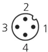
| Pin / connection core coloursof ifm |
| 1 brown |
| 2 white2 (operating output) |
| 3 blue |
| 4 bOldF1 (operating output) |
sockets
Programming
| 1 | 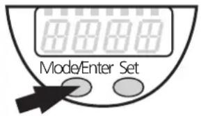  | Press the Mode/Enter button several times until the respective parameter is displayed. |
| 2 | 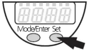 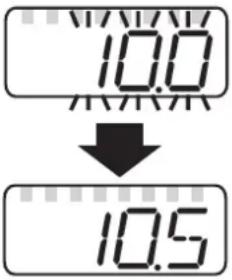 | Press the Set button and keep it pressed. The current parameter value flashes for 5s, then the value is increased* (incremental by pressing briefly or scrolling by holding pressed). |
| 3 | 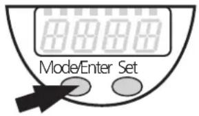 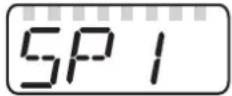 | Press the Mode/Enter button briefly (= acknowledgement). The parameter is displayed again, the set parameter value becomes effective. |
| 4 | Change more parameters: Start again with step 1. | Finish programming: Wait for 15s or press the Mode/Enter button until the current measured value is indicated again. |
*Decrease the value: Let the display of the parameter value move to the maximum setting value. Then the cycle starts again at the minimum setting value.
Timeout: If no button is pressed for 15s during the setting procedure, the unit returns to the Run mode with unchanged values.
Locking / Unlocking: The unit can be electronically locked to prevent unwanted adjustment of the set parameters: Press both pushbuttons for 10s (until Lio displayed). To unlock: Press both pushbuttons for 10s (until uLoc is displayed).
Units are delivered from the factory in the unlocked state.
With the unit in the locked state is indicated when you try to change parameter values.
The unit can be programmed before or after installation.
Controls and indicating elements
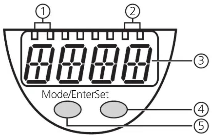
| 1 | 2 x LED green | Lighting LED = set display unit:- LED 1 = level in cm.- LED 2 = level in inch. |
| 2 | 2 x LED yellow | Switching status indication; lights if the respective output is switched.- LED 1 = OUT1 (freely configurable output).- LED 2 = OUT2 (freely configurable output). |
| 3 | 4-digit alphanumeric display | - Indication of the current level.- Operating and fault indication.- Indication of the parameters and parameter values. |
| 4 | Set pushbutton | - Setting of the parameter values (scrolling by holding pressed; incremental by pressing briefly). |
| 5 | Mode / Enter pushbutton | Selection of the parameters and menu points,acknowledgement of the parameter values. |
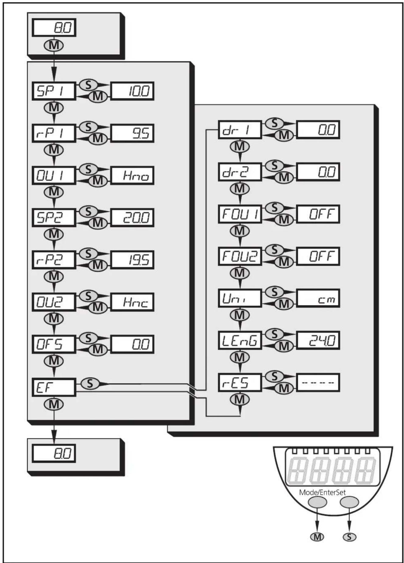
Menu structure
flowchart
graph TD
    A["80"] --> B["M"]
    B --> C["SP1 S M 100"]
    C --> D["M̄"]
    D --> E["rP1 S M 95"]
    E --> F["M̄"]
    F --> G["OU1 S M Hno"]
    G --> H["M̄"]
    H --> I["SP2 S M 200"]
    I --> J["M̄"]
    J --> K["rP2 S M 195"]
    K --> L["M̄"]
    L --> M["OU2 S M Hnc"]
    M --> N["M̄"]
    N --> O["OFS S M 00"]
    O --> P["M̄"]
    P --> Q["EF S"]
    Q --> R["M̄"]
    R --> S["80"]

    T["dr1 S M 00"] --> U["M̄"]
    U --> V["drc2 S M 00"]
    V --> W["M̄"]
    W --> X["FOU1 S M OFF"]
    X --> Y["M̄"]
    Y --> Z["FOU2 S M OFF"]
    Z --> AA["M̄"]
    AA --> AB["Un S M cm"]
    AB --> AC["M̄"]
    AC --> AD["LEnG S M 240"]
    AD --> AE["M̄"]
    AE --> AF["rES S M ----"]
    AF --> AG["M̄"]

    subgraph Mode/EnterSet
        direction TB
        direction LR
        Mode/EnterSetMode["Mode/EnterSet"]
        Mode/EnterSetModeM
        Mode/EnterSetModeS
        Mode/EnterSetModeM
        Mode/EnterSetModeS
        Mode/EnterSetModeM
        Mode/EnterSetModeS
        Mode/EnterSetModeM
        Mode/EnterSetModeS
        Mode/EnterSetModeM
        Mode/EnterSetModeS
        Mode/EnterSetModeM
        Mode/EnterSetModeS
        Mode/EnterSetModeM
        Mode/EnterSetModeS
        Mode/EntSetModeM
        Mode/EntSetModeS
        Mode/EntSetModeM
        Mode/EntSetModeS
        Mode/EntSetModeM
        Mode/EntSetModeS
        Mode/EntSetModeM
        Mode/EntSetModeS
        Mode/EntSetModeM
        Mode/EntSetModeS
        Mode/EntSetModeM
        Mode/EntSetModeS
        Mode/EntSetModeM
        Mode/EntSetModeS,
        Mode/EntSetModeM
        Mode/EntSetModeS
        Mode/EntSetModeM
        Mode/EntSetModeS
        Mode/EntSetModeM
        Mode/EntSetModeS
        Mode/EntSetModeM
        Mode/EntSetModeS
        Mode/EntSetModeM
        Mode/EntSetModeS
        Mode/EntSetModeM
        Mode/EntSetModeS
        Mode/End
For programming carry out the following steps in the indicated order.
| ParameterStep P | ||
| 1 Access the extended functionsPress the Mode/Enter button until EF is displayed.Press the Set button. The first parameter of the extended menu is now displayed. You can access the corresponding parameter value by pressing the Set button again. Pressing the Mode/Enter button accesses the following parameters. | EF | |
| 2 Selection of the display unitSet the required display unit: cm / inch.Select the display unit before setting values for the parameters SPx, rPx, LEnG, OFS. This avoids rounding errors generated internally during the conversion of the units and enables exact setting of the values.Setting at the factory: Uni = cm. | Uni | |
| 3 Setting of the probe lengthThis setting is only necessary if the probe length differs from the delivered length.On delivery: LEnG = probe length L (see scale drawing page 41).Determine the actual probe length (measured from the lower edge of the thread to the probe end). Round this value to 5 mm / 0.2 inch.Activate the parameter LEnG. Enter the new value.For the setting range of the probe length please refer to the table on page 38 | LEng | |
| 4 Setting of the offset valueThe zone between tank bottom and lower edge of the measuring probe can be entered as offset value (OFS). Thus display and switch points refer to the real level.Setting at the factory: OFS = 0.The setting values OFS are indicated in the table on page 38.Please note: Select OFS, before setting values for the parameters SPx, rPx and OP. This avoids inadvertent maladjustment. | OFS | |
| 5 Setting of the switching parametersSP1:setpoint 1 = upper limit value at which the switching output OUT1 changes its switching status.rP1:reset point 1 = lower limit value at which the switching output OUT1 changes its switching status.OU1:switching function for the switching output OU1.4 settings can be selected:hysteresis (H..) or window function (F..)as normally open (.no) or normally closed (.nc). | SP1r-P1OU1 | |
| SP2:setpoint 2 = upper limit value at which the switching output OUT2 changes its switching status.rP2:reset point 2 = lower limit value at which the switching output OUT2 changes its switching status.OU2:switching function for the switching output OU2.4 settings can be selected:hysteresis (H..) or window function (F..)as normally open (.no) or normally closed (.nc).Setting ranges for SPx and rPx → page 38.Note:If the upper setpoint is used as an overflow protection, the setting OUx = Hnc (nc function) is recommended. The principle of normally closed operation ensures that wire break or cable break is also detected | SP2r-P2OU2 | |
| 6 Setting of the switch-off delaydr1:switch-off delay for the switching output OUT1dr2:switch-off delay for the switching output OUT2• Setting range: 0...5 s in steps of 0.2 s.The switch-off delay is only effective when setting the switching function hysteresis (OUx = H..). | dr-1dr-2 | |
| 7 Response of the outputs in case of a faultFOU1:Wrong response for the switching output OUT1FOU2:Wrong response for the switching output OUT22 settings can be selected:On= output switches ON in case of a fault.OFF= output switches OFF in case of a fault.Factory setting: FOU1 / FOU2 = OFF.Faults are: faulty hardware, too low a signal quality.Overflow is not considered to be a fault! | FOU1FOU2ENGLISH | |
Reset to factory settings
Resets all settings to the state on delivery. Before the factory reset check the possible effects on your application!
- Press the "Mode/Enter" button until rES is displayed
- Press the "Set" button and keep it pressed until "----" is displayed,
- Press the "Mode/Enter" button briefly. The display then returns to rES.
ParameterStep P
r-ES
Setting range for the probe length (applies to all LR70 type units)
| cm | inch | |
| Setting range | 15...70 | 6.0...27.6 |
| in steps of | 0.5 | 0.2 |
The probe can be replaced. Probes are available as accessories in different lengths.
Setting range for OFS (applies to all LR70 type units)
| cm | inch | |
| Setting range | 0...100 | 0...39.4 |
| in steps of | 0.5 | 0.2 |
Setting range for SPx, rPx
| LR7022 (L = 24)*cm inch | LR7023 (L = 45)*cm inch | LR7024 (L = 70)*cm inch | |
| SPx | 1.5...20.0 0.6...7.8 | 1.5...41.0 0.6...16.2 | 1.5...66.0 0.6...26.0 |
| rPx | 1.0...19.5 0.4...7.6 | 1.0...40.5 0.4...16.0 | 1.0...65.5 0.4...25.8 |
| ΔL* | 0.5 0.2 | 0.5 0.2 | 0.5 0.2 |
*L = probe length [cm] on delivery; ΔL = increments
The values apply to the probe length on delivery and OFS = 0.
- rPx is always smaller than SPx. Reducing the value for SPx to a value ≤ rPx also shifts the position of rPx.
- If the difference between rPx and SPx is small (approx. 3 x increment), increasing rPx also increases SPx.
- If the difference between rPx and SPx is great, rPx remains at the set value
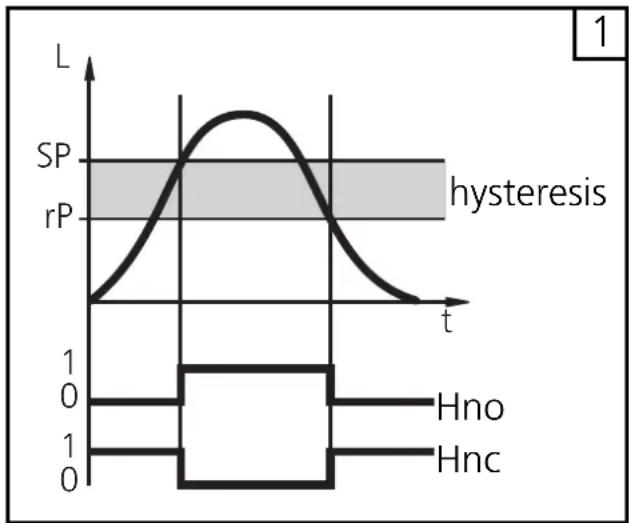
Hysteresis function (Hno, Hnc) (fig. 1):
The hysteresis keeps the switching state of the output stable if the level of the medium varies about the preset value.
With the level rising, the output switches when the switch-on point has been reached (SPx). With the level falling, the output does not switch back until the level falls below the reset point rPx.
The hysteresis for SPx can be adjusted: First the switch-on point is set, then the switch-off point with the requested distance.
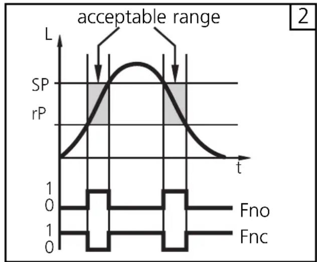
Window function (Fno, Fnc) (fig 2)
The window function enables the monitoring of a defined acceptable range. When the level of the medium varies between the switch-on point (SPx) and the switch-off point (rPx), the output is switched (window function / NO) or not switched (window function / NC).
The width of the window can be set by means of the difference between SPx and rPx. SPx = upper value, rPx = lower value.
line
| t | L | | ---- | ----- | | 0 | 0 | | 1 | SP | | 2 | rP | | 3 | SP | | 4 | rP | | 5 | SP | | 6 | rP | | 7 | SP | | 8 | rP | | 9 | SP | | 10 | rP | | 11 | SP | | 12 | rP | | 13 | SP | | 14 | rP | | 15 | SP | | 16 | rP | | 17 | SP | | 18 | rP | | 19 | SP | | 20 | rP | | 21 | SP | | 22 | rP | | 23 | SP | | 24 | rP | | 25 | SP | | 26 | rP | | 27 | SP | | 28 | rP | | 29 | SP | | 30 | rP | | 31 | SP | | 32 | rP | | 33 | SP | | 34 | rP | | 35 | SP | | 36 | rP | | 37 | SP | | 38 | rP | | 39 | SP | | 40 | rP | | 41 | SP | | 42 | rP | | 43 | SP | | 44 | rP | | 45 | SP | | 46 | rP | | 47 | SP | | 48 | rP | | 49 | SP | | 50 | rP | | 51 | SP | | 52 | rP | | 53 | SP | | 54 | rP | | 55 | SP | | 56 | rP | | 57 | SP | | 58 | rP | | 59 | SP | | 60 | rP | | 61 | SP | | 62 | rP | | 63 | SP | | 64 | rP | | 65 | SP | | 66 | rP | | 67 | SP | | 68 | rP | | 69 | SP | | 70 | rP | | 71 | SP | | 72 | rP | | 73 | SP | | 74 | rP | | 75 | SP | | 76 | rP | | 77 | SP | | 78 | rP | | 79 | SP | | 80 | rP | | 81 | SP | | 82 | rP | | 83 | SP | | 84 | rP | | 85 | SP | | 86 | rP | | 87 | SP | | 88 | rP | | 89 | SP | | 90 | rP | | 91 | SP | | 92 | rP | | 93 | SP | | 94 | rP | | 95 | SP | | 96 | rP | | 97 | SP | | 98 | rP | | 99 | SP | | 100 | rP |L = level
line
| t | SP | rP | | ---- | ---- | ---- | | 0 | 0 | 0 | | 1 | 1 | 0 | | 2 | 0 | 0 |Installation and set-up / Operation
After mounting, wiring and programming check whether the unit operates correctly.
Operating and fault indication:
| CAL | Initialisation after power on. |
| XX.X | Level indication. |
| ---- | During operation: level below the active zone.During programming: Feedback during factory reset: all parameters reset to factory setting". |
| FULLXX.X | Maximum measuring range is reached or exceeded."FULL" and the indication of the maximum level alternate every second (= warning overflow). |
| Loc | Unit electronically locked, programming not possible.For unlocking press the two programming buttons for 10 s. |
| uLoc | Feedback: unit is unlocked / programming is possible again. |
| Err0 | Fault in the electronics (the unit must be replaced). |
| Err1 | - Measured signal below the safe evaluation range. Clean the probe and the process connection. Check mounting (the minimum distances may not have been adhered to).- The level exceeded the block distance by more than 10 mm.Reduce the level, attach a spout if possible.- The level reaches the state "empty" or "full" more quickly than allowed (plausibility check). Possible causes: cleaning or maintenance of the probe or tank, contact with the probe when switched on. |
| SC1, SC2 | Flashing: short circuit in the switching output 1, 2. |
| SC | Flashing: short circuit in both switching outputs. |
Carry out a reset (power off and on again) after rectifying the fault and to reset the error message.
Read the set parameter values:
- The parameter names are scrolled with each pressing of the "Mode/Enter" button.
- When the "Set" button is pressed briefly, the corresponding parameter value is displayed for 15s.
Output response in different operating states
| OUT1 | OUT2 | |
| Initialisation | OFF | OFF |
| Normal operating | according to the level and OU1 setting | according to the level and OU2 setting |
| Fault (Err0, Err1) | OFF for FOU1=OFFON for FOU1=On | OFF for FOU2=OFFON for FOU2=On |
Technical data
| Operating voltage [V] ..... 18 ... 30 DCCurrent rating [mA] ..... 200Short-circuit protection; reverse polarity protection / overload protectionVoltage drop [V] ..... < 2.5Current consumption [mA] ..... < 80Accuracy of switch point [% of the final value of the measuring range] ± 5Repeatability [% of the final value of the measuring range] ..... ± 2Maximum speed of the change of level [mm/s] ..... 100Dielectric constant medium ..... > 20Maximum tank pressure [bar] ..... 0.5 |
| Housing material . stainless steel (304S15); FKM; NBR; PBT; PC; PEI; TPE/V; PTFEMaterials (wetted parts) ..... stainless steel (303S22); PTFE; NBRProtection ..... IP 67, IIIOperating temperature [°C] ..... 0...60Medium temperature [°C] ..... 0...80Storage temperature [°C] ..... -25...80Storage temperature [°C] ..... -25 ... 80Shock resistance [g] ..... 12 (DIN EN 60068-2-29, 11 ms)Vibration resistance [g] ..... 2.5 (RMS, 1...1000 Hz)EMC EN 61000/4/2 ESD: ..... 4/8 kVEN 61000/4/3 HF radiated: ..... 10 V/mEN 61000/4/4 Burst: ..... 2 kVEN 61000/4/6 HF conducted: ..... 10 V |
Applications
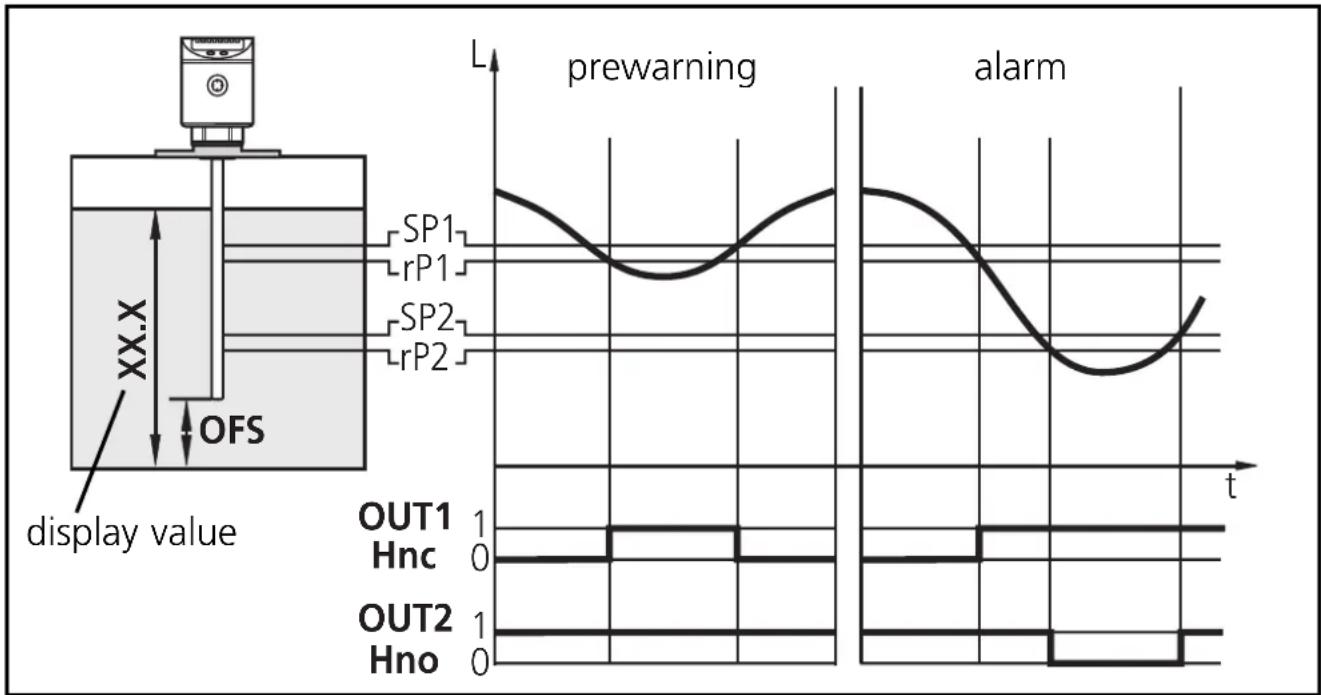
Minimum level monitoring with prewarning and alarm
| Switching output 1: prewarning | |
| SP1 | slightly above rP1 (to suppress wave movements) |
| r-P1 | below preset level →prewarning, start refilling |
| OU1 | hysteresis function, normally closed (Hnc) |
| Switching output 2: alarm | |
| SP2 | min. value reached again →alarm reset |
| r-P2 | below min. value →alarm |
| OU2 | hysteresis function, normally open (Hno) |
line
| Time | Signal | Value | |------|-------------|-------| | 0 | SP1 | High | | 1 | rP1 | Medium| | 2 | SP2 | Low | | 3 | rP2 | Medium| | 4 | SP1 | High | | 5 | rP1 | Medium| | 6 | SP2 | Low | | 7 | rP2 | Medium| | 8 | SP1 | High | | 9 | rP1 | Medium| | 10 | SP2 | Low | | 11 | rP2 | Medium| | 12 | SP1 | High | | 13 | rP1 | Medium| | 14 | SP2 | Low | | 15 | rP2 | Medium| | 16 | SP1 | High | | 17 | rP1 | Medium| | 18 | SP2 | Low | | 19 | rP2 | Medium| | 20 | SP1 | High | | 21 | rP1 | Medium| | 22 | SP2 | Low | | 23 | rP2 | Medium| | 24 | SP1 | High | | 25 | rP1 | Medium| | 26 | SP2 | Low | | 27 | rP2 | Medium| | 28 | SP1 | High | | 29 | rP1 | Medium| | 30 | SP2 | Low | | 31 | rP2 | Medium| | 32 | SP1 | High | | 33 | rP1 | Medium| | 34 | SP2 | Low | | 35 | rP2 | Medium| | 36 | SP1 | High | | 37 | rP1 | Medium| | 38 | SP2 | Low | | 39 | rP2 | Medium| | 40 | SP1 | High | | 41 | rP1 | Medium| | 42 | SP2 | Low | | 43 | rP2 | Medium| | 44 | SP1 | High | | 45 | rP1 | Medium| | 46 | SP2 | Low | | 47 | rP2 | Medium| | 48 | SP1 | High | | 49 | rP1 | Medium| | 50 | SP2 | Low | | 51 | rP2 | Medium| | 52 | SP1 | High | | 53 | rP1 | Medium| | 54 | SP2 | Low | | 55 | rP2 | Medium| | 56 | SP1 | High | | 57 | rP1 | Medium| | 58 | SP2 | Low | | 59 | rP2 | Medium| | 60 | SP1 | High | | 61 | rP1 | Medium| | 62 | SP2 | Low | | 63 | rP2 | Medium| | 64 | SP1 | High | | 65 | rP1 | Medium| | 66 | SP2 | Low | | 67 | rP2 | Medium| | 68 | SP1 | High | | 69 | rP1 | Medium| | 70 | SP2 | Low | | 71 | rP2 | Medium| | 72 | SP1 | High | | 73 | rP1 | Medium| | 74 | SP2 | Low | | 75 | rP2 | Medium| | 76 | SP1 | High | | 77 | rP1 | Medium| | 78 | SP2 | Low | | 79 | rP2 | Medium| | 80 | SP1 | High | | 81 | rP1 | Medium| | 82 | SP2 | Low | | 83 | rP2 | Medium| | 84 | SP1 | High | | 85 | rP1 | Medium| | 86 | SP2 | Low | | 87 | rP2 | Medium| | 88 | SP1 | High | | 89 | rP1 | Medium| | 90 | SP2 | Low | | 91 | rP2 | Medium| | 92 | SP1 | High | | 93 | rP1 | Medium| | 94 | SP2 | Low | | 95 | rP2 | Medium| | 96 | SP1 | High | | 97 | rP1 | Medium| | 98 | SP2 | Low | | 99 | rP2 | Medium| | 100 | SP1 | High | | ... (display value) - prewarning; alarm - display value - prewarning; display value - alarm - display value - alarm - alarm - alarm - alarm - alarm - alarm - alarm - alarm - alarm - alarm - alarm - alarm - alarm - alarm - alarm - alarm - alarm - alarm - alarm - alarm - alarm - alarm - alarm - alarm - alarm - alarm - alarm - alarm - alarm - alarm - alarm - alarm - alarm - alarm - alarm - alarm - alarm - alarm - alarm - alarm - alarm - alarm - alarm - alarm - alarm - alarm - alarm - alarm - alarm - alarm - alert- If the level is below rP1, output 1 switches until liquid is refilled. If SP1 is reached again, output 1 switches back.
- If the level is above SP2, output 2 switches. If the level falls below rP2 or if there is a wire break, output 2 switches back.
- By setting SP1 the maximum level can be controlled/monitored: The value of SP1 determines up to which level (max) is to be refilled. When the maximum level is reached, this is signalled by the LED OUT1 going out and output 1s witching off.
Applications
Pumping station
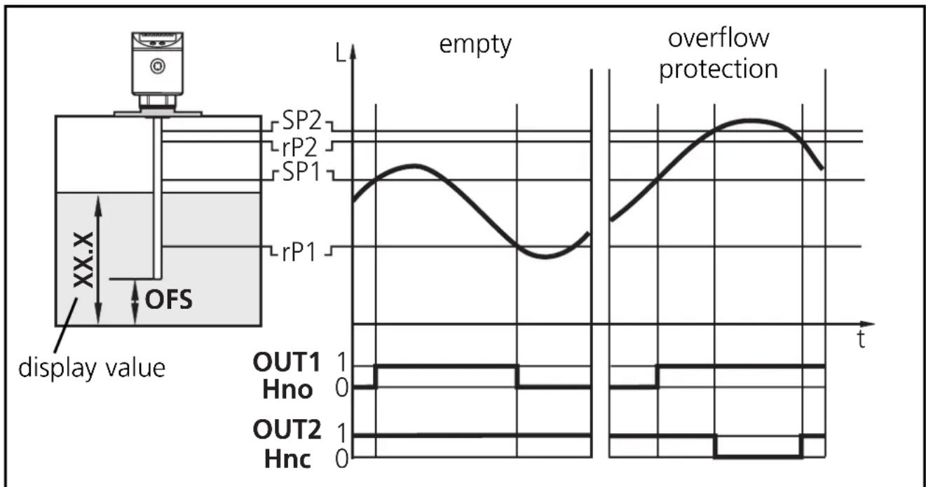
Empty the vessel with overflow protection
| Switching output 1: control to empty vessel | |
| SP I | upper value exceeded →submersible pump ON |
| r-P I | lower value reached →submersible pump OFF |
| OU I | hysteresis function, normally open (Hno) |
| Switching output 2: overflow protection | |
| SP2 | maximum value exceeded →alarm |
| r-P2 | slightly below SP2 (to suppress wave movements) |
| OU2 | hysteresis function, normally closed (Hnc) |
line
| Time | Flow Description | |------|------------------------| | 0 | OUT1 Hno | | 0 | OUT2 Hnc | | 0 | SP1 | | 0 | SP2 | | 0 | rP1 | | 0 | rP2 | | 0 | empty | | 0 | overflow protection |- If SP1 is exceeded, output 1 switches (submersible pump ON). When the level is below rP1 again the output switches back (submersible pump OFF).
- If SP2 is exceeded or if there is a wire break, output 2 switches off.
Applications
Storage vessel
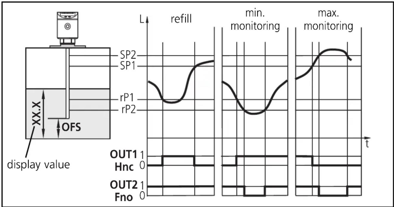
Monitoring of the acceptable range (alarm) and level control
| Switching output 1: refilling | |
| SP I | upper preset value reached →finish refilling |
| r-P I | below lower preset value →start refilling |
| OU I | hysteresis function, normally closed (Hnc) |
| Switching output 2: safety function min - max | |
| SP2 | max. value exceeded →alarm |
| r-P2 | below min. value →alarm |
| OU2 | window function, normally open (Fno) |
line
| Time | Display Value (L) | |------|-------------------| | 0 | SP2 | | 5 | SP1 | | 10 | rP1 | | 15 | rP2 | | 20 | max | | 25 | min | | 30 | max | | 35 | min | | 40 | max | | 45 | max | | 50 | max | | 55 | max | | 60 | max | | 65 | max | | 70 | max | | 75 | max | | 80 | max | | 85 | max | | 90 | max | | 95 | max | | 100 | max |- If the level is below rP1, output 1 switches until liquid is refilled. If SP1 is reached again, output 1 switches back.
- If the level is below rP2 or above SP2 or if there is a wire break, output 2 switches OFF (→alarm).
- The logical operation between the outputs 1 and 2 indicates whether there is overflow or the actual level is below the minimum level.
- Overflow: output 1 and output 2 switched off.
- Below min. value: output 1 switched on and output 2 switched off.
Scale drawing
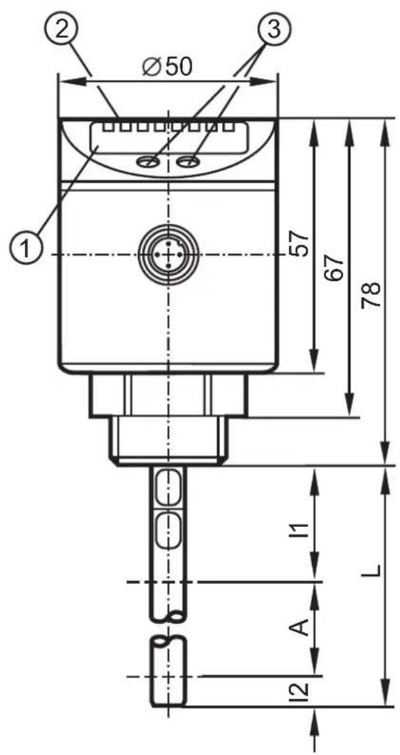
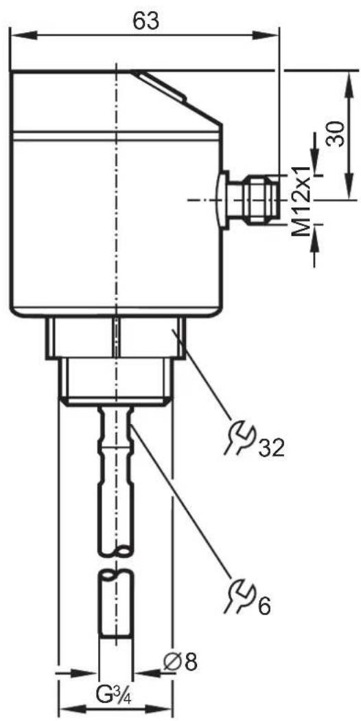
| LR7022 LR7023 LR7024 | |||
| cm inch | cm inch | cm inch | |
| L = probe length | 24 9.5 | 45 17.7 | 70 27.6 |
| A = active zone | 19 7.5 | 40 15.8 | 65 25.6 |
| I_1 (inactive zone 1) | 4 1.6 4 1.6 4 | 1.6 | |
| I_2 (inactive zone 2) | 1 0.4 1 0.4 1 | 0.4 | |
| 1 | 4-digit alphanumeric display | ||
| 2 | LEDs | ||
| 3 | Programming buttons | ||
ENGLISH
Contenue
natural_image
Diagram of a vertical device with directional arrows indicating flow or movement, no text or symbols present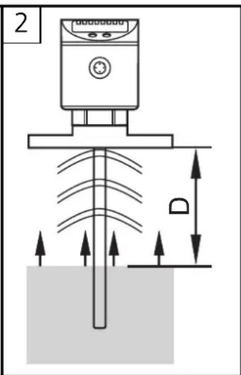
natural_image
Technical line drawing of a mechanical device with labeled component R (no text or symbols beyond label)Broche / raccordement
1 brun
line
| Signal | Time (t) | Value | |------------|----------|-------| | SP1 | 0 | Peak | | rP1 | 0 | Peak | | SP2 | 0 | Peak | | rP2 | 0 | Peak | | OUT1 | 0 | 1 | | Hnc | 0 | 0 | | OUT2 | 0 | 1 | | Hno | 0 | 0 |line
| Time | vider | Protection Contre le Débordement | |------|-------|----------------------------------| | t | SP1 | 0 | | t | SP2 | 0 | | t | rP1 | 0 | | t | rP2 | 0 | | t | SP2 | 1 | | t | SP1 | 1 | | t | SP2 | 1 | | t | rP1 | 1 | | t | rP2 | 1 | | t | SP1 | 1 | | t | SP2 | 1 | | t | rP1 | 1 | | t | rP2 | 1 | | t | SP1 | 1 | | t | SP2 | 1 | | t | rP1 | 1 | | t | rR | 1 | | t | rP2 | 1 | | t | SP1 | 1 | | t | SP2 | 1 | | t | rP1 | 1 | | t | rP2 | 1 | | t | SP1 | 1 | | t | SP2 | 1 | | t | rP16 | 1 | | t | rR | 1 | | t | rR | 1 | | t | rR | 1 | | t | SP16 | 1 | | t | SP26 | 1 | | t | rP16 | 1 | | t | rP26 | 1 | | t | SP16 | 1 | | t | SP26 | 1 | | t | rP16 | 1 | | t | rR | 1 | | t | rR | 1 | | t | rR | 1 | | t | SP16 | 1 | | t | SP26 | 1 | | t | rP16 | 1 | | t | R | 1 | | t | R | 1 | | t | R | 1 | | t | R | 1 | | t | R | 1 | | t | R | 1 | | t | R | R | | t | R | R | | t | R | R | | t | R | R | | t | R | R | | t | R | R | | t | R | R | | t | R | R | | t | R | R | | t | R | R | | t | R | R | | t | R | R | | t | R | R | | t | R | R | | t | R | R | | t | R | R | | t | R | R | | t | R | R | | t | R | R | | t | R | R | | t | R | R | | t | R | R | | t | R | R | | t | R | R | | t | R | R | | t | R | R | | t | R | R | | t | R | R | | t | R | R | | t | R | R | | t | R | R | | t | R | R | | t | R | R | | t | R | R | | t | R | R | | t | R | R | | t | R | R | | t | R | R | | t | R | R | | t | R | R | | t | R | R | | t | R | R | | t | R | R | | t | R | R | | t | R | R | | t | R | R | | t | R | R | | t | R | R | | t | R | R | | t | R | R | | t | R | R | | t | R | R | | t | R | R | | t | R | R | | t | R | R | | t | R | R | | t | R | R | | t | R | R | | t | R | R | | t | R | R | | t | R | R | | t | R | R | | t | R | R | | t | R | R | | t | R | R | | t | R | R | | t | R | R | | t | R | R | | t | R | S | | T = V (XX.X) (OFS) (Valeur affichée) (OUT1) (Hno) (OUT2) (Hnc) (OUT3) (OUT4) (OUT5) (OUT6) (OUT7) (OUT8) (OUT9) (OUT10) (OUT11) (OUT12) (OUT13) (OUT14) (OUT15) (OUT16) (OUT17) (OUT18) (OUT19) (OUT20) (OUT21) (OUT22) (OUT23) (OUT24) (OUT25) (OUT26) (OUT27) (OUT28) (OUT29) (OUT30) (OUT31) (OUT32) (OUT33) (OUT34) (OUT35) (OUT36) (OUT37) (OUT38) (OUT39) (OUT40) (OUT41) (OUT42) (OUT43) (OUT44) (OUT45) (OUT46) (OUT47) (OUT48) (OUT49) (OUT50) (OUT51) (OUT52) (OUT53) (OUT54) (OUT55) (OUT56) (OUT57) (OUT58) (OUT59) (OUT60) (OUT61) (OUT62) (OUT63) (OUT64) (OUT65) (OUT66) (OUT67) (OUT68) (OUT69) (OUT70) (OUT71) (OUT72) (OUT73) (OUT74) (OUT75) (OUT76) (OUT77) (OUT78) (OUT79) (OUT80) (OUT81) (OUT82) (OUT83) (OUT84) (OUT85) (OUT86) (OUT87) (OUT88) (OUT89) (OUT90) (OUT91) (OUT92) (OUT93) (OUT94) (OUT95) (OUT96) (OUT97) (OUT98) (OUT99) (OUT100)|


- Operating instructions
- Electronic level sensor
- Inhalt
- Funktionsübersicht
- Zu 3:
- Important notes for the user of these instructions
- Safety instructions
- Function and features
- Applications
- Restriction of the application area
- Functional overview
- Measuring principle
- Mounting
- On 1 and 2:
- On 3:
- Installation location / installation environment
- Adaptation of the probe
- Notes:
- Installation of the sensor using a flange plate
- Electrical connection
- Programming
- Reset to factory settings
- Hysteresis function (Hno, Hnc) (fig. 1):
- Window function (Fno, Fnc) (fig 2)
- Installation and set-up / Operation
- Read the set parameter values:
- Pumping station
- Storage vessel
- Scale drawing
- Contenue
Brand : IFM
Model : LR7022
Category : Detector