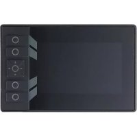
CR1059 - Interface IFM - Free user manual and instructions
Find the device manual for free CR1059 IFM in PDF.


User questions about CR1059 IFM
0 question about this device. Answer the ones you know or ask your own.
Ask a new question about this device
Download the instructions for your Interface in PDF format for free! Find your manual CR1059 - IFM and take your electronic device back in hand. On this page are published all the documents necessary for the use of your device. CR1059 by IFM.
USER MANUAL CR1059 IFM
Operating instructions Process and dialogue module
ecomat
Display
CR1150
Contents
1 Preliminary note 3
1.1 Symbols used 3
1.2 Warnings used 3
2 Safety instructions.... 4
3 Intended use.... 5
3.1 Properties 5
4 Installation.... 7
4.1 Mounting accessories 7
4.2 General installation instructions 7
4.2.1 UV protection 7
4.2.2 Location for mounting accessories 7
4.2.3 Light sensor and status LED 8
4.3 Panel mounting / control cabinet installation 9
4.3.1 Safety instructions for panel mounting / control cabinet installation....9
4.3.2 Installation with installation kit 10
4.3.3 Panel cutout 10
4.3.4 Mounting steps 10
4.4 Surface mounting with RAM® mount system 11
4.4.1 Mounting steps 12
4.5 Other installation types 12
5 Electrical connection.... 13
5.1 Wiring 13
5.2 Connection accessories 13
5.3 Connection technology 13
5.4 General wiring information 14
5.5 Operating voltage and circuit breakers 15
5.6 Shield connection 15
5.7 Ethernet interface 16
5.8 USB interfaces 16
5.8.1 Short-circuit protection 17
5.9 Selection of loudspeakers.... 17
6 Set-up.... 18
6.1 General.... 18
6.2 Getting started 18
6.3 Set-up 18
6.4 Required documentation.... 18
6.5 Function of the internal temperature sensor 19
7 Maintenance, repair and disposal 20
7.1 Battery change 20
7.2 Cleaning the display surface 20
7.3 Cleaning the housing surface 21
7.4 Repair 21
7.5 Disposal 21
1 Preliminary note
You will find instructions, technical data, approvals and further information using the QR code on the unit / packaging or at www.ifm.com.
1.1 Symbols used
√ Requirement
Instructions
Reaction, result
[...] Designation of keys, buttons or indications
→ Cross-reference

Important note
Non-compliance may result in malfunction or interference.

Information
Supplementary note
1.2 Warnings used
ATTENTION
Warning of damage to property

CAUTION
Warning of personal injury
▷ Slight reversible injuries may result.

WARNING
Warning of serious personal injury
▷ Death or serious irreversible injuries may result.
2 Safety instructions
- The unit described is a subcomponent for integration into a system.
- The system architect is responsible for the safety of the system.
-
The system architect undertakes to perform a risk assessment and to create documentation in accordance with legal and normative requirements to be provided to the operator and user of the system. This documentation must contain all necessary information and safety instructions for the operator, the user and, if applicable, for any service personnel authorised by the architect of the system.
-
Read this document before setting up the product and keep it during the entire service life.
- The product must be suitable for the corresponding applications and environmental conditions without any restrictions.
- Only use the product for its intended purpose (→ Intended use).
- If the operating instructions or the technical data are not adhered to, personal injury and/or damage to property may occur.
- The manufacturer assumes no liability or warranty for any consequences caused by tampering with the product or incorrect use by the operator.
• Installation, electrical connection, set-up, programming, configuration, operation and maintenance of the product must be carried out by personnel qualified and authorised for the respective activity. - Protect units and cables against damage.
- Replace damaged units, otherwise the technical data and safety will be impaired.
- Observe applicable documents.
3 Intended use
The ecomat
Display process and dialogue module is a programmable graphic display for controlling, parameter-setting and operation of mobile machines and plants. It is suited for use at an operating altitude of 3000 m above sea level even under severe conditions, such as an extended temperature range and mechanical stress (Technical data: www.ifm.com and indicated standards).
Permitted use:
- in mobile machines with supply from on-board systems (with battery) of 12 V DC or 24 V DC nominal voltage
- in an industrial environment as a permanently installed unit with supply from SELV/PELV according to the technical data
• even in wet environments
• even outdoors, if necessary with additional UV protection
Communication with other system components, such as decentralised I/O modules, takes place via CAN, Ethernet and USB interfaces. Together with the Linux operating system they form a universal platform for networking and communication with other CAN devices, networks or PCs.

By default, the device is not intended for direct connection to IT structures. If this application is required, the users have to implement it (e.g. by using their own additional components).

This is a class A product. This product may cause radio interference in domestic areas. ▶ If required, take appropriate EMC screening measures.

The unit is not approved for safety-related tasks in the field of operator protection.
3.1 Properties
- 5" colour display
- Closed metal housing suitable for panel mounting and surface mounting outside or in the cabin
• Freely programmable to IEC 61131-3 with target visualisation - 64-bit controller and Embedded Linux operating system
• CAN interfaces with CANopen and SAE J1939 protocol - Ethernet and USB interfaces
| Feature | CR1150 |
| Touch screen | - |
| Freely programmable, backlit buttons | 4 |
| Navigation keys with button | 1 |
| Ethernet interfaces | 1 |
| CAN interfaces | 2 |
| ifm plug&play (CAN based) | - |
| USB 2.0 interfaces | 1 |
| Analogue video inputs | - |
| Digital inputs BL | - |
| Digital outputs 2.5 A | - |
| Line In | - |
| Speaker output | 1 |
| Headphone output | - |
| Controller | Dual Core with GPU, 800 MHz |
| RAM | 1 GB |
| FLASH | 2 GB |
●= available
-= not available
4 Installation
4.1 Mounting accessories
The unit is supplied without mounting accessories.
Depending on the intended installation location and type of mounting, the following mounting accessories are available:
• EC0730, installation kit for panel mounting
- EC1410... EC1414, RAM® mount system for surface mounting
More information about available accessories at www.ifm.com
4.2 General installation instructions
The following applies to all types of mounting:
▶ The responsibility for the compliance with the requirements concerning mounting of the device in the application with regard to shock, vibration, acceleration and weight lies with the system architect.
The unit front withstands shock up to IK07 without damage.
ATTENTION
Higher impact stress > IK07
▷ Damage possible
▷ Protection rating and electrical protection might be impaired
▷ Risk of injury possible
▶ If necessary, the system creator must take external measures to protect the device depending on the requirements of the corresponding application.
▶ Replace damaged devices, otherwise the technical data and safety will be impaired.
On the back, the pressure compensation element, the service cover and the connector areas are to be protected by taking external measures, if necessary.
4.2.1 UV protection
The device meets requirements for methods of exposure to laboratory light sources and weathering according to DIN EN ISO 4892-2. Test criteria: Procedure A, cycle 1: Test duration 1000 h, without affecting the functioning. The display remains legible.
Permanent outdoor use requires additional measures to protect the device from UV radiation (e.g. shading, UV filter) in order to fulfil the expected life. When the device is not in use, it should be covered by a sunscreen.
It is the responsibility of the system creator to check the suitability of the UV protection for the application area of the system and, if necessary, to adapt it.
4.2.2 Location for mounting accessories
The back of the device has been prepared for fixing the mounting accessories.
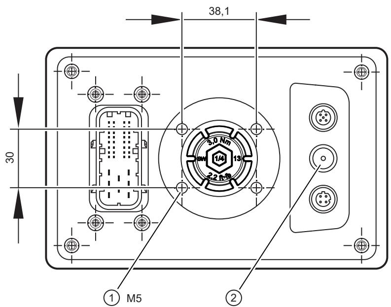
1: 4 x M5 threaded hole for RAM ® mount system / for the fixing profile of the installation kit
2: pressure compensation element
ATTENTION
The device is equipped with a pressure compensation element. Sealing or closing the corresponding ventilation ducts with elastic materials may damage the device.
▶ Do not use any sealing materials in the area around the pressure compensation elements.
4.2.3 Light sensor and status LED
The device is equipped with a light sensor. It is used to adapt the brightness of the display and the operating elements automatically to the ambient brightness conditions.

1: Light sensor
2: Status LED
▶ Avoid construction measures that cover up the light sensor.
The status LED indicates the operating states of the device.
4.3 Panel mounting / control cabinet installation
4.3.1 Safety instructions for panel mounting / control cabinet installation
The specifications for the operating temperature apply in front of and behind the installation surface.
The dimensions for the control panel cut-out are a basic prerequisite for the requirements concerning electrical protection, fire protection and protection rating of the device / system. However, this alone does not ensure compliance with the requirements. See the following safety instructions. They must be complied with for the risk assessment by the system creator (→ Safety instructions).

WARNING
The housing does not meet the requirements concerning protective earth. Only functional grounding is possible.
▷ Risk of electrical shock in case of hazardous active voltages in the control cabinet behind the installation surface.
▶ The system creator must separate hazardous active voltages / parts behind the installation surface from the housing of the device and its circuits by means of double / reinforced insulation (air creepage distances, solid insulation).
▶ Take single-fault safety into account (e.g. individual core detached from the terminal → use cable ties).
▶ The responsibility for the electrical protection of the system lies with the system creator.
When installing the device in a control cabinet, the following requirements concerning fire protection apply:
If installed according to the information given in 4.3, the device itself complies with the requirements of the IEC (or DIN EN) 61010-2-201 for a closed device to prevent fire from spreading.

WARNING
The damping strip (installation kit) has no flammability rating and thus presents no fire obstacle.
▷ Fire protection for the system might not be given or might be restricted.
▶ The system creator has to ensure the fire protection depending on the requirements of his/her application, if necessary by means of external precautions.
▶ The responsibility for the fire protection of the system lies with the system creator.
Using the installation kit does not ensure the protection rating of the system with the installed device. The protection rating depends on the properties of the control panel / control cabinet (e.g. thickness, material, surface characteristics, torsional stiffness).

CAUTION
The use of the installation kit does not ensure the requirements concerning the protection rating of the system with the installed device.
▷ Protection rating and electrical protection might be impaired
▶ The system creator has to ensure the protection rating depending on the requirements of his application, if necessary by means of external precautions.
The responsibility for the protection of the system with the installed device lies with the system creator.
4.3.2 Installation with installation kit
The installation kit enables horizontal, vertical or overhead mounting of the device in a panel cut-out.
This type of mounting is suited for materials with a thickness from 1 to 10 mm.
Longer set screws have to be used for material thicknesses >10 mm. They are not supplied with the mounting accessories.
The fixing profile, spacers, M5 hexagon nuts, washers, M5 set screws and damping strips required for mounting are supplied with the installation kit.

Fig. 1: Fixing profile of the installation kit
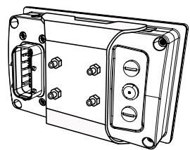
Fig. 2: Dialogue module with mounted installation kit
Use the fixing profile of the mounting kit only together with a suitable spacer and the damping strip.
4.3.3 Panel cutout
▶ Make a cut-out.
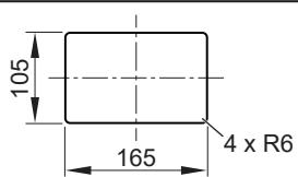
Tolerances: ± 0.5 mm
Fig. 3: Panel cut-out
4.3.4 Mounting steps
▶ Screw the set screws into the M5 thread on the back of the device: Location for mounting accessories ( → ☐ 7).
▶ Attach damping strips to the device.
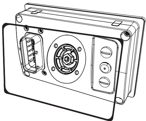
Fig. 4: Damping strips
▶ Insert the device into the cut-out.
▶ Insert the spacer suitable for the panel thickness. The thickness of the spacers corresponds to the panel thickness. If necessary, use several spacers on top of each other.
▶ Screw the fixing profile to the back of the device. Tightening torque of the M5 hexagon nuts: 5±0.5 Nm
ATTENTION
Contact corrosion between the mounting screws and the housing.
▷ Damage to the device
▶ Do not use copper or nickel-plated materials for the bolting elements.
▶ Use zinc-plated screws.
▶ In very corrosive environments such as extremely salty air, use screws with surface finishing on a zinc/nickel basis with thick-film passivation and sealing.
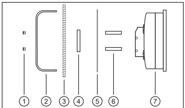
Fig. 5: Mounting principle
1: M5 hexagon nuts
2: fixing profile
3: panel cut-out
4: spacer
5: damping strips
6: set screws
7: dialogue module
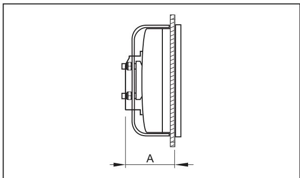
Fig. 6: Dimensions
Installation depth A = device depth (approx. 48 mm)
Installation depth with the attached connector: approx. 72 mm
4.4 Surface mounting with RAM® mount system
Using the RAM ® mount components, available as accessories, the dialogue unit can be used as a firmly mounted desktop unit. Two ball heads allow variable orientation of the unit.
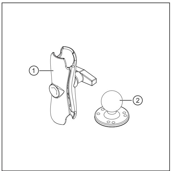
Fig. 7: RAM ® mount components
1: mounting arm with fastening screw
2: mounting plate with ball head

Fig. 8: Dialogue module with mounted RAM ® mount system
You will find more information about the available RAM ® mount components at: www.ifm.com
4.4.1 Mounting steps
▶ Screw the mounting plate to the back of the device.
Usable M5 thread depth: ≤ 8 mm
tightening torque M5: 5 ±0.5 Nm
▶ Screw second mounting plate / ball head of the selected RAM ® mount component on suitable surface according to RAM ® mount indications.
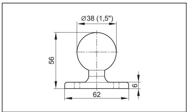
Fig. 9: Mounting plate with ball head

Fig. 10: Hole dimensions
Tightening torque: 5 ±0.5 Nm
▶ Slightly loosen the fastening screw of the mounting arm.
▶ Place the mounting arm onto the ball heads and tighten the fastening screw.
4.5 Other installation types
Permissible installation types:
Panel mounting / control cabinet installation ( → ☐ 9)
Surface mounting with RAM® mount system (→ 11)

All other installation types are in the sole responsibility of the system creator.
5 Electrical connection

▶ Disconnect the machine from the mains supply before installation; if necessary, also disconnect any independently supplied input / output load circuits.
▶ Observe the national and international regulations for the installation of electrical equipment.
▶ Observe the requirements according to EN 60204.
Accessible surfaces of the device are insulated from the circuits with basic insulation to IEC 61010-1 (secondary circuit with max. 32 V DC, supplied from the mains circuit up to 300 V of overvoltage category II).
GND of the supply is connected via EMC suppression capacitors on the shield connection (metal housing) of the device.
The external wiring has to be carried out in a way that ensures the required separation from other circuits.
5.1 Wiring
Wiring: Technical data: www.ifm.com

The terminals may only be supplied with the signals specified in the technical data or on the device label

Unconnected pins must not be connected to the cable harness and its individual cores must be sealed.
ATTENTION
Reverse polarity protection not ensured in case of power supply SELV/PELV on VBB 30 and VBB 0 )
Reverse polarity protection is only ensured in case of supply via the on-board system (via a battery), if the polarity of the supply is reversed as a whole (battery connected incorrectly). The basic principle of the reverse polarity protection is that the upstream fuses are quickly switched off in case of excessive current. In case of supply via SELV/PELV, reverse polarity protection is not ensured.
▷ Damage to the device possible
▶ Ensure that the ends of the cables are properly connected to the connector before connecting the latter to the device, also in case of supply via the on-board system.
5.2 Connection accessories
More information about available accessories at www.ifm.com
5.3 Connection technology

Observe all notes on connection technology.
▶ Note the device label.
▶ Use M12 connectors with gold-plated contacts.
▶ The M12 connection parts in the device comply with the ingress resistance requirements of the standard EN 61076-2-101. To adhere to the protection rating, only cables certified to this standard must be used. The system architect undertakes to ensure the ingress resistance of cables they have cut to length.
▶ Carry out the fitting according to the indications of the cable manufacturer. The permitted maximum is 10 Nm.
▶ During installation, place the M12 connector vertically so that the coupling nut will not damage the thread.
▶ Unused sockets are equipped with protective caps (included).
Tightening torque: 1.3 ±0.1 Nm
▶ Use 40-pole connectors with individually sealed cores to ensure protection rating IP 67.

Only connect the connector when the supply voltage is disconnected.
"Hot plugging" is not permitted.
"Hot plugging" is permitted at the USB type A connector of the connected M12 adapter.

The ingress resistance of cables that users have cut to length must be guaranteed.
▶ Use twisted-pair cables for the CAN / IFM connection.
The CAN bus is internally protected against short circuit to VBB and GND.

For CAN / IFM cables ≥ 30 m, ensure appropriate protection against surge (e. g. shielded cables).
▶ For the Ethernet connection, use a minimum category 5 (Cat 5) cable.
▶ Audio loudspeaker output: floating twisted-pair wiring.
5.4 General wiring information
Wiring of the connectors: Technical data: www.ifm.com

Fig. 11: Connectors (back of the device)
1: Supply, audio, CAN, service
2: USB0
3: ETHO
ATTENTION
Wrong connection may cause damage to the device.
▶ Observe the safety instructions.
ATTENTION
The short-circuit / reverse polarity protection of the device applies to the operating voltage connections. A short circuit between operating voltage VBBx and USB / Audio might cause damage to the device.
▶ Lay supply and signal cables away from the device using the shortest possible route.
▶ Provide all outgoing cables with a strain relief 200 mm behind the cable entry.
Maximum cable lengths:
- USB ≤ 1.8 m
- Ethernet ≤ 30m
- Audio ≤ 30 m
Minimum operating quality Audio:
There might be interference to audio circuits in the vicinity of strong HF sources or due to ESD. This may result in audible and visible distortion.
5.5 Operating voltage and circuit breakers
▶ The individual electric circuits must be protected in order to protect the whole system. Automotive spade-type fuses are recommended.
| Designation | Connector 1 | Operating voltage | Nominal value fuse | Required triggering characteristics |
| VBB15 | Pin 119 | 8...16 V DC and 16...32 V DCLgnition-starter switch | 3 A | Tfuse ≤ 120 s at max. 6.25 A |
| VBB30 | Pin 121 | 8...16 V DC | 5 A | Tfuse ≤ 120 s at max. 6.25 A |
| 16...32 V DC | 3 A | Tfuse ≤ 120 s at max. 6.25 A | ||
| VBB0 | Pin 114 | 8...16 V DC and 16...32 V DC | 15 A | - |
| Digital inputs | Pin 115, 116, 89, 97, 110 | 8...16 V DC and 16...32 V DC | 3 A | Tfuse ≤ 120 s at max. 6.25 A |
Tab. 1: Terminal designation to DIN 72552
Supply cables of the inputs can be secured together with the circuit breaker for VBB15 .
ATTENTION
Load dump and surge without connection of VBB0
▷ Destruction of the device possible!
▶ Always connect VBB0 , even if the outputs are not used or are not available.
5.6 Shield connection
To ensure the protection of the device against electrical interference and to ensure the safe function of the device, the housing has to be connected to the body / GND of the supply using the shortest possible route.
▶ Establish the connection between the device and the ground of the vehicle using the intended screw for RAM ® Mount installation. If possible, use the thread next to the 40-pole AMP connector. Max. tightening torque: 5 Nm
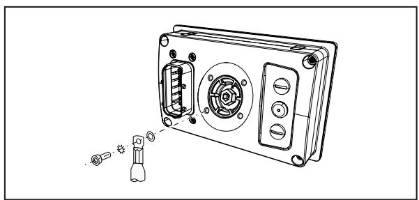
Fig. 12: Shield connection
To avoid contact corrosion on the shield connection of the housing, do not use any copper or nickel-plated materials for the bolting elements!
▶ In very corrosive environments such as extremely salty air, use screws with surface finishing on a zinc/nickel basis with thick-film passivation and sealing.
5.7 Ethernet interface
Communication interfaces are insulated from each other, from other circuits and from touchable device surfaces with basic insulation according to IEC62368-1 as an external circuit.
▶ Use a screened CAT5 cable. STP (Shielded Twisted Pair), to EIA/TIA-568 Length max. 30 m
The max. cable length depends, for example, on the bus topology, the selected operating mode (10/100 Mbits/s) or the quality of the connectors.
- ▶ Use screened connector housings and connect the screen of the Ethernet cable to the connector housing. - ▶ Do not lay the Ethernet cable in parallel to live cables.
Interference due to external influences Faulty or insufficient radio interference suppressors in other electrical equipment, such as inverters or generators, as well as voltage fluctuations when switching on/off electric loads may lead to problems with the data transmission.
5.8 USB interfaces
Wiring: Technical data: www.ifm.com
This USB interface is connected to a USB connector in the control panel or in the dashboard. It is used for the connection of USB 2.0 devices.
The supply of external USB devices via the USB interface is protected against overload and overvoltage. Max. continuous current: 500 mA

Fig. 13: USB connection via M12 connector
1: dialogue module
2: USB connector, for example, in the control panel or in the dashboard
3: USB device
A: Permanent connection: dialogue module – USB connector
▶ Use a prewired cable.
(M12 connector, B-coded on USB socket, type A, watertight, cable length 1.5 m, wires twisted and screened)
▶ If self-assembling cables, please only use cables according to USB 2.0 specification.
Keep length "B" as short as possible and position the USB connector in the immediate vicinity of the dialogue module. The length "B" considerably influences the quality of the USB data transmission.
B: Connection: USB connector – USB device
▶ Use a connection cable with the designation "Full Speed/High Speed" (= USB connection cable with twisted and screened cores according to USB 2.0 specification).
▶ Do not use more than one USB cable for the connection.
5.8.1 Short-circuit protection
ATTENTION
The USB interface (M12 connector) is not protected against short circuits with a live wire outside the following voltage ranges:
+5 V DC -0.3...6.0 V DC (pin 1)
-Data -0.3...3.6 V DC (pin 2)
+Data -0.3...3.6 V DC (pin 3)
ID -0.3...3.6 V DC (pin 4)
▷ A short circuit will destroy the USB interface.
5.9 Selection of loudspeakers
For optimum audio output, use 8 Ω loudspeakers.
6 Set-up
6.1 General
The factory setting of the device shows a demo application. The installed recovery app can be used to load any suitable firmware version to the device.
Factory setting:
IP address 192.168.82.247
Subnet mask: 255.255.255.0
Gateway IP address: 192.168.82.1
The user is responsible for the safe function of the application programs which he created himself. If necessary, they must additionally carry out an approval by corresponding supervisory and test organisations according to the national regulations.
6.2 Getting started
▶ Connect the device to the notebook/PC via the Ethernet interface.
▶ Switch on the notebook/PC; check the IP settings of the notebook/PC and change them if necessary.
Internet protocol: TCP/IP
IP address 192.168.82.xxx (except for .247, s.a.)
Subnet mask: 255.255.255.0
Gateway IP address: 192.168.82.1
▶ Switch on the operating voltage of the dialogue module.
▷ Shortly after the unit is switched on, the start image appears for approx. 10 to 15 seconds. During this time, the booting process is running in the background.
After booting, the App Launcher opens automatically.
6.3 Set-up
The set-up allows setting the device parameters directly via the local display or the web interface of the device. Select the set-up button in the App Launcher to start the local set-up.
While the App Launcher is shown, entering the device IP address (e.g. 192.168.82.247) via the connected web browser takes you to the web set-up.
After leaving the set-up, a project can be loaded. Libraries (.lib) are available to use the operating elements, interfaces and other internal functions of the device. They have to be integrated into the application program.
6.4 Required documentation
In addition to the CODESYS programming system, the following documents are required for programming and set-up of the device:
- Programming manual ecomat
Display
The manuals are available for download on the internet: www.ifm.com
CODESYS online help: included in CODESYS installation (www.ifm.com, in the download area with registration)
6.5 Function of the internal temperature sensor
The internal temperature sensor of the device can be read out with the software.
The device primarily heats up due to the following factors:
- solar radiation
- Ambient temperature
• Installation conditions - External heating
• Current consumption (display illumination etc.)
The device heats up considerably under demanding operating conditions. The device temperature must not exceed the maximum permissible value (Technical data: www.ifm.com).
The value provided by the internal temperature sensor can e.g. be used for the following actions:
- Reduction of the display brightness to decrease internal heating
- Warning the operator about the heating indicating an upcoming switch-off of the display
- Switch-off of the display
ATTENTION
Internal temperature exceeds the permissible value (Technical data: www.ifm.com)
▷ Malfunction or damage to the device possible
▶ Reduce device temperature.
▶ Take appropriate measures to prevent further heating up of the device.
7 Maintenance, repair and disposal
7.1 Battery change
The battery may only be changed by a qualified person.
▶ Before changing the battery, fully separate the device from supply voltage.
Battery may explode if handled incorrectly. Do not recharge or disassemble the battery, nor dispose of it in fire.

1: service cover
2: battery
▶ Replace the battery if the displayed time is permanently wrong after the device is switched on.
ATTENTION
The protection rating does not apply if the service cover is open and there is no ESD protection of the accessible contacts inside
▷ Damage to the device possible
▶ Clean the area around the service cover before opening it.
▶ Remove the service cover on the back of the device (width across flats 13 mm or 1/4 ").
▶ Protect inside of device, sealing areas and sealing of the service cover from soiling and humidity.
▶ When changing the battery, take ESD precautions.
▶ Remove the battery and replace it with a new one.
Observe the polarity: positive side up
Battery type (Technical data: www.ifm.com)
▶ Check sealing areas and sealing for soiling. Clean them, if necessary.
▶ Screw the service cover with 3.0 Nm to restore the protection rating (width across flats 13 or 1/4 ").
▶ Reset the system time via device set-up or application (see programming manual ecomat
Display).
Disposal of used batteries: Disposal ( → ☐ 21)
7.2 Cleaning the display surface
Unsuitable cleaning agents and chemicals can damage the display surface. The following agents are not suitable for cleaning displays:
• Chemicals dissolving plastics such as methylated spirit, benzine, thinner, alcohol, acetone or ammonia.
• paper towels, crepe paper etc.
• abrasive cleaners etc.
• shine-producing cleaning agents, such as polish or wax
▶ Clean the device from dirt using a soft, chemically untreated and dry cloth.
▶ In case of severe soiling, use a damp cloth (water).

Micro-fibre cloths without chemical additives are recommended.
7.3 Cleaning the housing surface
▶ Disconnect the device.
▶ Clean the device from dirt using a soft, chemically untreated and dry cloth.
▶ In case of severe soiling, use a damp cloth (water).
7.4 Repair
▶ The device must only be repaired by the manufacturer. Observe the safety instructions. → Safety instructions
7.5 Disposal
▶ Dispose of used batteries in accordance with national environmental regulations.
Do not dispose of used batteries with household waste.
▶ After use, dispose of the unit in an environmentally friendly way in accordance with the applicable national regulations.


- 1 PRELIMINARY NOTE
- 1.1 SYMBOLS USED
- 1.2 WARNINGS USED
- 2 SAFETY INSTRUCTIONS
- 3 INTENDED USE
- 3.1 PROPERTIES
- 4 INSTALLATION
- 4.1 MOUNTING ACCESSORIES
- 4.2 GENERAL INSTALLATION INSTRUCTIONS
- 4.2.1 UV PROTECTION
- 4.2.2 LOCATION FOR MOUNTING ACCESSORIES
- 4.2.3 LIGHT SENSOR AND STATUS LED
- 4.3 PANEL MOUNTING / CONTROL CABINET INSTALLATION
- 4.3.1 SAFETY INSTRUCTIONS FOR PANEL MOUNTING / CONTROL CABINET INSTALLATION
- 4.3.2 INSTALLATION WITH INSTALLATION KIT
- 4.3.3 PANEL CUTOUT
- 4.3.4 MOUNTING STEPS
- 4.4 SURFACE MOUNTING WITH RAM® MOUNT SYSTEM
- 4.4.1 MOUNTING STEPS
- 4.5 OTHER INSTALLATION TYPES
- 5 ELECTRICAL CONNECTION
- 5.1 WIRING
- 5.2 CONNECTION ACCESSORIES
- 5.3 CONNECTION TECHNOLOGY
- 5.4 GENERAL WIRING INFORMATION
- 5.5 OPERATING VOLTAGE AND CIRCUIT BREAKERS
- 5.6 SHIELD CONNECTION
- 5.7 ETHERNET INTERFACE
- 5.8 USB INTERFACES
- 5.8.1 SHORT-CIRCUIT PROTECTION
- 5.9 SELECTION OF LOUDSPEAKERS
- 6 SET-UP
- 6.1 GENERAL
- 6.2 GETTING STARTED
- 6.3 SET-UP
- 6.4 REQUIRED DOCUMENTATION
- 6.5 FUNCTION OF THE INTERNAL TEMPERATURE SENSOR
- 7 MAINTENANCE, REPAIR AND DISPOSAL
- 7.1 BATTERY CHANGE
- 7.2 CLEANING THE DISPLAY SURFACE
- 7.3 CLEANING THE HOUSING SURFACE
- 7.4 REPAIR
- 7.5 DISPOSAL
Brand : IFM
Model : CR1059
Category : Interface