
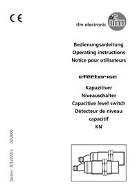
SI1001 - Detector IFM - Free user manual and instructions
Find the device manual for free SI1001 IFM in PDF.

| Product type | Flow detector (flow controller) |
| Brand | IFM |
| Model | SI1001 |
| Supply voltage | 20...36 V DC |
| Output current | 400 mA, short-circuit and overload protected |
| Power consumption | < 80 mA |
| Measuring range (liquid) | 3...300 cm/s |
| Measuring range (gas) | 200...3000 cm/s |
| Fluid temperature | -25...80 °C |
| Ambient temperature | -25...80 °C |
| Maximum pressure | 300 bar |
| Protection rating | IP 67 |
| Housing material | PBT-GF 20 |
| Probe material | Stainless steel 316L or titanium depending on variant |
| Process connection | M18 x 1.5 (adapter required) |
| Display | 10 LED bar (green, orange, red) for flow and switching status |
| Settings | HI-Teach (max flow), LO-Teach (min flow), switching threshold, excessive flow monitoring, remote adjustment |
| Lock function | Button lock to prevent accidental operation |
| Response time | 1...10 s (typical 3...8 s) |
| Maintenance | Periodically clean the probe with a soft cloth; use a vinegar-based cleaner for stubborn deposits |
| Repairability | No specific spare parts; contact IFM customer service |
| Accessories | Process connection adapters (order separately) |
Frequently Asked Questions - SI1001 IFM
User questions about SI1001 IFM
0 question about this device. Answer the ones you know or ask your own.
Ask a new question about this device
Download the instructions for your Detector in PDF format for free! Find your manual SI1001 - IFM and take your electronic device back in hand. On this page are published all the documents necessary for the use of your device. SI1001 by IFM.
USER MANUAL SI1001 IFM
natural_image
Technical line drawing of a mechanical component with a shaft and threaded end (no text or symbols)Kurzanleitung
- Installieren
natural_image
Pure architectural or structural diagram with vertical columns and horizontal beams, no text or symbols presentLED = grün LED = orange LED = rot
Inhalt
natural_image
Pure mechanical component diagram without any text, numbers, or symbols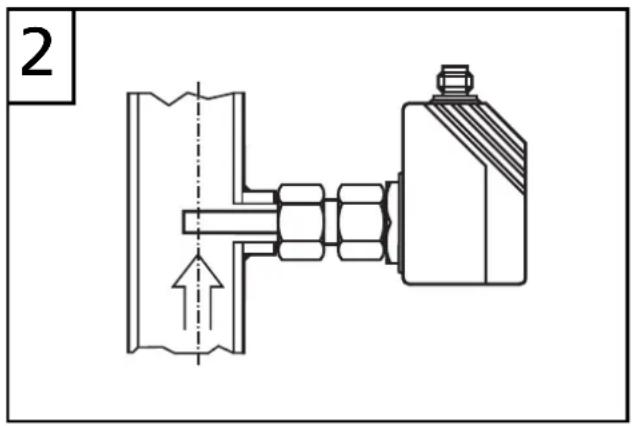
1 = BN (braun), 2 = WH (weiß), 3 = BU (blau), 4 = BK (schwarz)

Brief adjustment instructions
- Installation
Mounting → page 24, electrical connection → page 26.
- HI-Teach
Apply the operating voltage.
After approx. 15s the unit is ready.
Allow the medium to flow through the system at the required maximum flow rate (HI).
Press the Learn/Set button and keep it pressed.
The green LEDs on the right and on the left flash,
after 5s the LED bar (green) fills from left to right
(release the button as soon as the first LEDs light).
The indication goes off briefly.
The unit stores the current flow as maximum flow.
flowchart
graph TD
    A["Structure with M/S labels"] --> B["LO HI"]
    B --> C["LO HI"]
    C --> D["LO HI"]
    D --> E["HI label"]
    style A fill:#f9f,stroke:#333
    style B fill:#ccf,stroke:#333
    style C fill:#cfc,stroke:#333
    style D fill:#fcc,stroke:#333
    style E fill:#ffc,stroke:#333
- The unit is ready for normal operation.
Further setting options ( page 27)
- The HI-Teach is sufficient for the majority of waterbased applications. Optional: adjustment to minimum flow (LO-Teach).
- Setting of the switch point (for changing the reaction time and excess gain).
- Setting for monitoring and optical indication of excess flow.
- Activate / deactivate the function for remote adjustment.
- Reset to factory settings.
Controls and visual indication
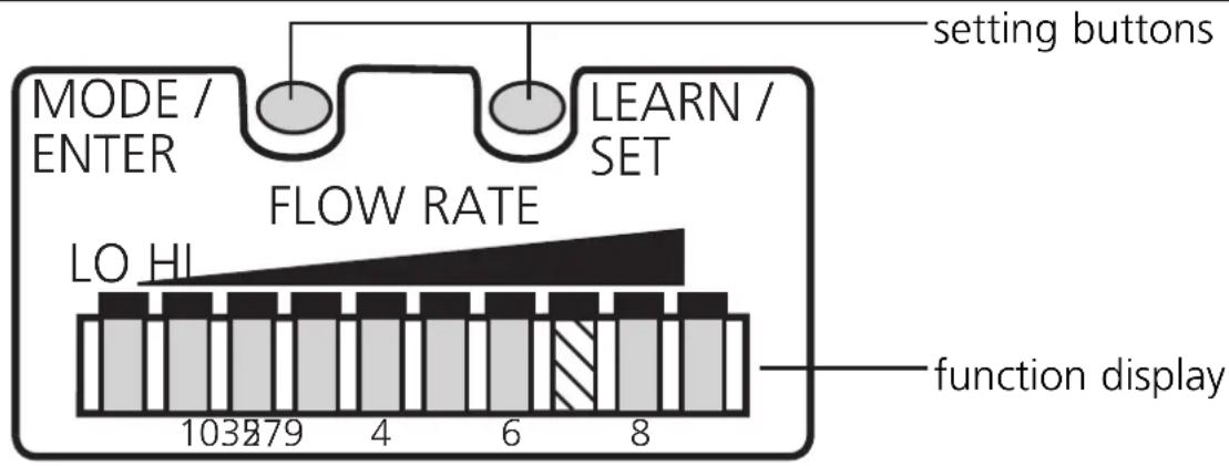
Function display (Run mode)
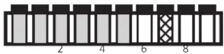
current flow within the display range (LED bar green)
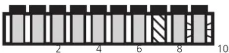
excess flow (LED 9 flashes)
natural_image
Pure architectural or structural diagram with vertical columns and horizontal beams, no text or symbols presentunderflow (LED 0 flashes)
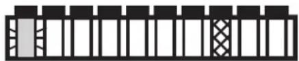
Indication of the switch point (SP):
LED orange: flow ≥ SP; LED red: flow < SP
Setting buttons
Mode / Enter:
- selection of the menu items and acknowledgement
Learn/Set: - adjustment to maximum / minimum flow;
- reset to factory settings
- setting of values (scrolling by holding pressed; incremental by pressing briefly)
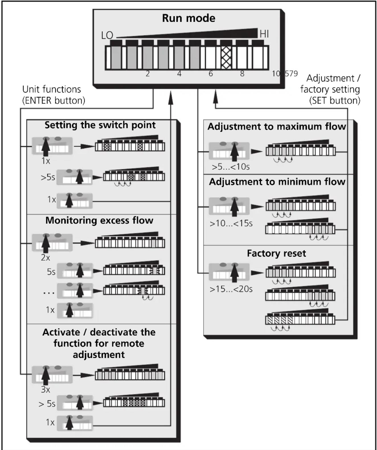
Menu structure
flowchart
graph TD
    A["Run mode"] --> B["Setting the switch point"]
    A --> C["Monitoring excess flow"]
    A --> D["Activate / deactivate the function for remote adjustment"]
    B --> E["1x >5s 1x"]
    C --> F["2x 5s ... 1x"]
    D --> G["3x >5s 1x"]
    E --> H["LO HI 2-4-6-8-10-579"]
    F --> I[">5...<10s"]
    G --> J[">10...<15s"]
    H --> K["Adjustment / factory setting (SET button)"]
    I --> L["Adjustment to maximum flow"]
    J --> M["Adjustment to minimum flow"]
    K --> N[">15...<20s"]
    L --> O["Factory reset"]
☐ LED = green LED = orange LED = red
Contents
Function and features ...... page 23
Installation . . . . . . . . . . . . . . . . . . . . . . . . . . . . . . . . . . . . . . . . . . . . . . page 24
Electrical connection . . . . . . . . . . . . . . . . . . . . . . . . . . . . . . . . . . . . . . . . page 26
Programming ...... page 27
Installation and set-up / Operation / Maintenance ..... page 29
Technical data . . . . . . . . . . . . . . . . . . . . . . . . . . . . . . . . . . . . . . . . . . . . . page 29
Programming diagrams / Technical information ..... page 30
Function and features
The flow monitor
• detects the flow velocity in liquid and gaseous media
- switches the output according to the programming (N.O./or-N.C./, programmable by wiring; → page 26)
- and indicates the relative flow value within the adjustable detection range by means of LEDs:
- LED 0 = lower limit of the detection range (maximum value / LO)
- LED 9 = upper limit of the detection range (minimum value / HI)
- It is also possible to indicate:
- Switching status (LED red: flow below the switch point, LED orange: flow has reached the switch point).
- Excess flow: LED 9 flashes if the flow is considerably higher (2 LEDs) than the display range.
- Underflow / flow standstill: LED 0 flashes if the flow is lower than the display range.
Installation
The unit is adaptable for various process fittings (adapters to be ordered separately as accessories).
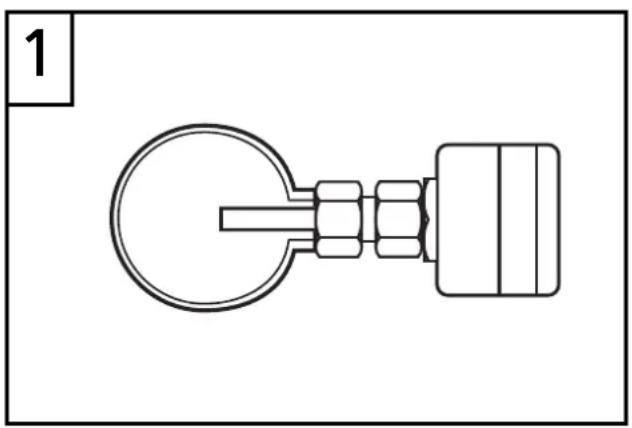
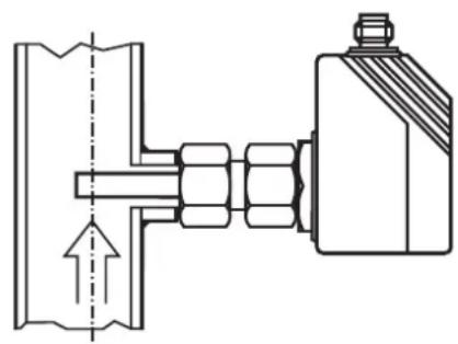
- In the case of horizontal pipes mount the unit from the side, if possible (fig. 1).
When the unit is to be mounted at the bottom of the pipe, it should be free from deposits.
When the unit is to be mounted at the top of the pipe, it should be completely filled with the medium to be monitored. - In the case of vertical pipes mount the unit in a place where the medium flows upwards (fig. 2).
natural_image
Pure mechanical component diagram without any text, numbers, or symbols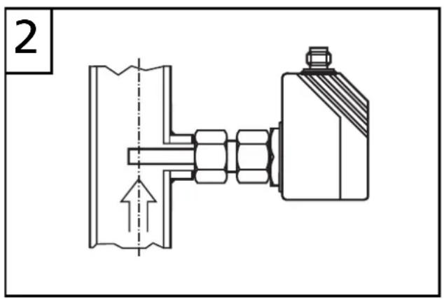
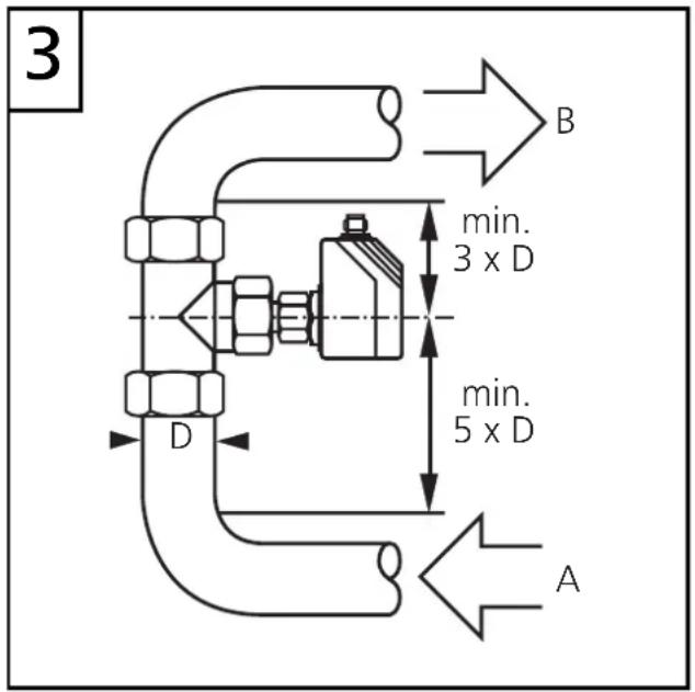
To avoid malfunction a minimum distance between the flow monitor and bends, valves, changes in cross-section or such like must be observed:
- Min. 5 x pipe diameter upstream (A),
- min. 3 x pipe diameter downstream (B).
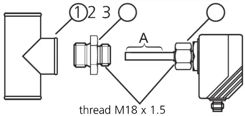
- Lubricate the nut (3) and all threads with grease to ensure the nut can be loosened and tightened several times.
Note: No grease must be applied to the sensor tip (A). - Screw the suitable adapter (2) onto the process fitting (1).
- Insert the flow monitor into the adapter. While keeping the unit aligned tighten the nut (3); (max. tightening torque 50Nm).
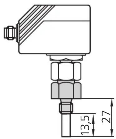
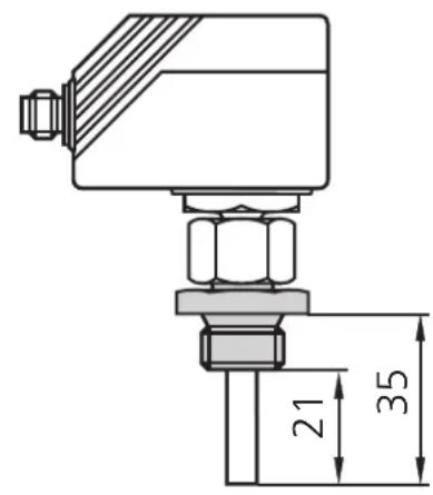
Insertion depth of the sensor: min. 12mm in the pipe. When the adapters are used which are available as accessories, the correct depth is ensured.
Note: The sensor tip must not touch the pipe wall.
| mounting dimension with M12 adapter | mounting dimension with G 14 adapter | mounting dimension with G 12 adapter |
 |  |  |
Electrical connection

The unit must only be connected by an electrician.
The national and international regulations for the installation of electrical equipment must be observed.
Voltage supply to EN50178, SELV, PELV.
The device shall be supplied from an isolating transformer having a secondary Listed fuse rated as noted in the following table.
| Overcurrent protection | ||
| Control-circuit wire size | Maximum protective device rating Ampere | |
| AWG (mm) | ^2 | |
| 26 (0.13) 1 | ||
| 24 (0.20) 2 | ||
| 22 (0.32) 3 | ||
| 20 (0.52) 5 | ||
| 18 (0.82) 7 | ||
| 16 (1.3 ) 10 | ||
Disconnect power before connecting the unit.
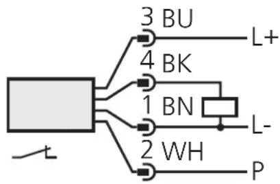
Wiring (=N.O. / = N.C.)
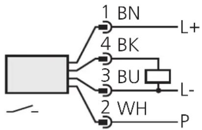
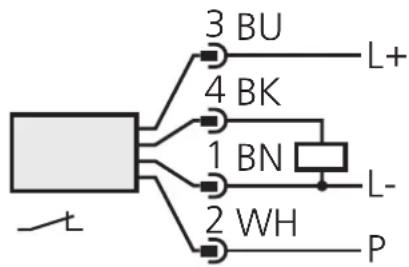
connector
view (sensor)
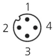
P = programming wire (for remote adjustment)
Core colours of ifm sockets:
1 = BN (brown), 2 = WH (white), 3 = BU (blue), 4 = BK (black)

If the function for remote adjustment is active:
Use 4-wire connection cables without a link between pins 2 and 4.
With 3-wire sockets with a link between pin 2 and pin 4 switching of the output stage triggers the remote adjustment!
Failure indication: In the case of a short circuit the function indication and the red LED row are lit alternately.
Programming
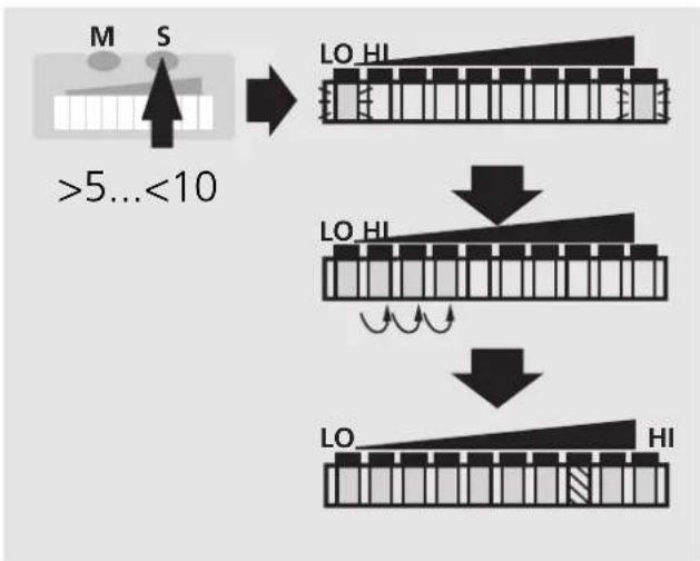
■Setting of the detection range HI-Teach
- Allow the medium to flow through the system at the required maximum flow rate.
- Press the Learn/Set button for >5...<10s (= adjustment to maximum flow / upper limit of the detection range).
Optional: LO-Teach
The HI-Teach is sufficient for the majority of waterbased applications. Optional: adjustment to minimum flow.
- Allow the medium to flow through the system at the required minimum flow rate or bring flow to a standstill.
- Press the Learn/Set button for >10...< 15s (= adjustment to minimum flow or flow standstill / lower limit of the detection range).
■ Remote adjustment via programming wire
Apply the operating voltage ( +U_B ) to pin 2 for the respective time.
■Setting of the switch point
- Press the Mode/Enter button briefly.
- Press the Learn/Set button for 5s,
- keep the Learn/Set button pressed or press the button several times until the requested switch point is set.
- Press the Mode/Enter button briefly.
■Monitoring excess flow
- Press the Mode/Enter button twice.
- Press the Learn/Set button for 5s, release the button when LED flashes.
- Press the Learn/Set button several times to shift the LED for the maximum display value.
- Press the Mode/Enter button briefly.
■Activate / deactivate the function for remote adjustment
- Press the Mode/Enter button three times.
- Press the Learn/Set button for 5s,
- keep the Learn/Set button pressed or press the button several times until the requested function is set (function active, when 3 LEDs on the right and 3 LEDs left are lit green; function not active, when the 4 LEDs in the middle are lit in red).
- Press the Mode/Enter button briefly.
■ Reset to factory settings
- Press the Learn/Set button for >15...<20s.
■The following applies to all setting procedures:
- If no button is pressed for 15s during the setting procedure, the unit returns to the operating mode with the parameter values unchanged.
- If adjustment has not been possible, all the red LEDs flash. The unit returns to the operating mode with the parameter values unchanged.
■Locking / Unlocking
The unit can be electronically locked to prevent unwanted adjustment of the set parameters: Press both setting buttons for 10s (the unit must be in Run mode). Indication goes out briefly (acknowledgement of locking / unlocking).
Units are delivered from the factory in the unlocked state.
If the unit is locked, it is possible to indicate
- the current switch point (press the Mode/Enter button once),
- the setting of the function “monitoring excess flow” (press the Mode/Enter button two times),
- the setting of the function for remote adjustment (press the Mode/Enter button three times).
Installation and set-up / Operation / Maintenance
After mounting, wiring and setting check whether the unit operates correctly. At power on, all LEDs light and go off one after the other.* The unit is then ready for operation.
*During this time the output is switched according to the programming: ON with the NO function and OFF with the NC function.
Failure indication: In the case of a short circuit the function indication and the red LED row are lit alternately.
Recommended maintenance
Check the sensor tip for build-up from time to time. Clean it with a soft cloth. If necessary, build-up which adheres firmly (e.g. lime) can be removed with a common vinegar cleansing agent.
Technical data
| Operating voltage [V] | 20 ... 36 DC1) |
| Current rating [mA] | 400; short-circuit protection; reverse polarity protection / overload protection |
| Voltage drop [V] | < 2.5 |
| Current consumption [mA] | < 80 |
| Liquids | |
| Medium temperature [°C] | -25 ... +80 |
| Setting range [cm/s] | 3 ... 300 |
| Greatest sensitivity [cm/s] | 3 ... 60 |
| Max. temperature gradient of medium [K/min] | 300 |
| Gases | |
| Medium temperature [°C] | -25 ... +80 |
| Setting range [cm/s] | 200 ... 3000 |
| Greatest sensitivity [cm/s] | 200 ... 800 |
| Response time [s] | 1 ... 10 |
| Power-on delay time [s] | 15, optically indicated |
| Pressure rating [bar] | 300 |
| Operating temperature [°C] | -25 ... +80 |
| Protection | IP 67 (IEC60529) / UL50) |
| Shock resistance [g] | 50 (DIN / IEC 68-2-27, 11 ms) |
| Vibration resistance [g] | 20 (DIN / IEC 68-2-6, 55-2000 Hz) |
| Housing material | PBT-GF 20 |
| Sensor material (SI10xx) | stainless steel (316S12); O-ring: FPM 8x1.5 gr 80° Shore A |
| Sensor material (SI11xx) | titanium; O-ring: FPM 8x1.5 gr 80° Shore A |
^1) to EN50178, SELV, PELV
Programming diagrams / Technical information
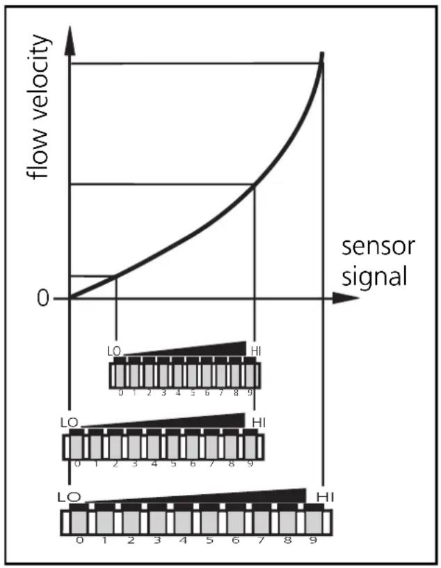
■Setting of the detection range
The detection range (window) is determined by:
- Adjustment to the required maximum flow (HI-Teach) = upper limit of the window. This setting is sufficient for the majority of waterbased applications.
- Additionally: adjustment to the required minimum flow / flow standstill (LO-Teach) = lower limit of the window (optional).
line
| sensor signal | flow velocity | | ------------- | ------------- | | 0 | 0 | | 1 | ~0.5 | | 2 | ~1.0 | | 3 | ~1.5 | | 4 | ~2.0 | | 5 | ~2.5 | | 6 | ~3.0 | | 7 | ~3.5 | | 8 | ~4.0 | | 9 | ~4.5 |- Adjustment to maximum flow (HI-Teach)
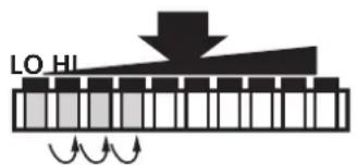
The unit detects the current flow and sets this value as the maximum value for the LED display (LED 9).
| 1 | Apply the operating voltage. After approx. 15s the unit is ready.Allow the medium to flow through the system at the required maximum flow rate. | ||
| 2 | 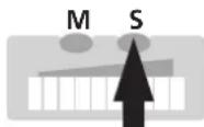 | 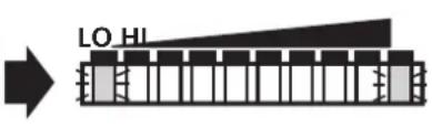 | Press the Learn/Set button and keep it pressed.The green LEDs on the right and on the left flash,after 5s the LED bar (green) fills from left to right (release the button as soon as the first LEDs light).The indication goes off briefly.The unit stores the current flow as maximum flow and passes into the operating mode. |
| >5...<10s | |||
 | |||
 | |||
 | |||
- Adjustment to minimum flow / flow standstill (LO-Teach), optional
The unit detects the current flow and sets this value as the minimum display value for the LED display. In normal operation the first green LED (LED 0) flashes when the flow falls below this value (or when it comes to a standstill).
NOTE: The LO-Teach operation may only be carried out after the HI-Teach operation.
| 1 | Allow the medium to flow through the system at the required minimum flow rate or bring to a standstill. | |
| 2 | 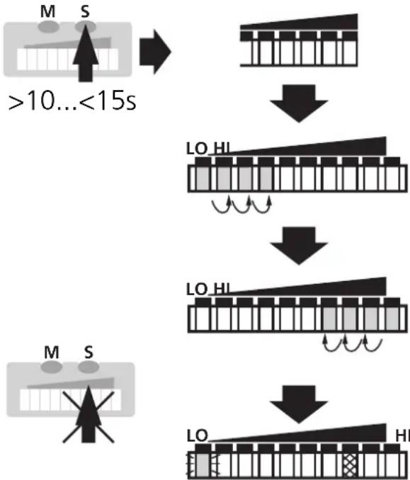 | Press the Learn/Set button and keep it pressed.The green LEDs on the right and on the left flash,after 5s the LED bar (green) fills from left to rightafter a further 5s the LED bar (gren) fills from right to left (release the button as soon as the first LEDs on the right light).The indication goes off briefly.The unit stores the current flow as minimum flow and passes into the operating mode. |
- Remote adjustment
You can also adjust the unit via the programming wire, if the function for remote adjustment is active. Apply the operating voltage ( +U_B ) to pin 2 (P) for the respective time: >5...<10s for HI-Teach; >10...<15s for LO-Teach
If the operating voltage is applied to pin 2 for more than 15s,
- all adjustments are set back to factory setting.
If the operating voltage is applied to pin 2 for more than 20s, - the adjustment does not become effective; the unit passes into the operating mode with unchanged values,
- the unit is locked (the buttons are inactive as long as the operating voltage is applied to pin 2).
■Setting of the switch point
The switch point is preset at the factory (LED 7). The setting influences the reaction time of the unit.
- High switch point = fast reaction in the case of flow decrease.
- Low switch point = fast reaction in the case of flow increase.
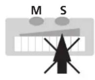
| 1 | 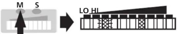 1 x 1 x | Press the Mode/Enter button briefly. The current switch point is indicated:LED lit: coarse setting, LED flashes: fine setting. |
| 2 | 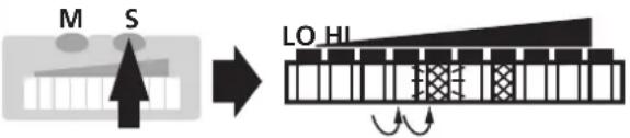 >5s >5s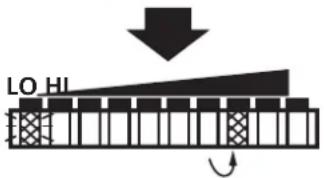 | Press the Learn/Set button and keep it pressed.After 5s the switch point is increased* (incremental by pressing briefly or scrolling by holding pressed).Indication:The flashing LED moves from left to right. After LED 9 has been reached the cycle starts again at LED 0. The LED which is constantly lit moves on by one position.** |
| 3 | 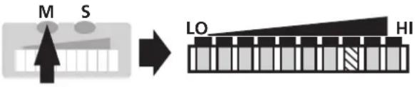 | Press the Mode/Enter button briefly (acknowledgement).The indication goes off briefly.The set switch point becomes effective; the unit passes into the operating mode. |
*Decrease the switch point: Let the flashing and lit LEDs move to the maximum setting value. Then the cycle starts again at the minimum setting value.
**Overflow: If the flashing LED and the lit LED exceed the maximum setting value, the cycle starts again at the minimum setting value.
■Monitoring excess flow
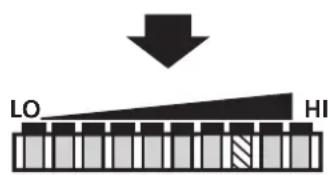
With this function the position of the display window within the detection range can be defined: Shift the LED for the maximum display value to position 8, 7, 6 or 5. In the case of maximum flow all LEDs from 0 up to this LED are lit. The LEDs above the range signal excess flow. If the switch point is above this range, the unit switches in the case of excess flow.
| 1 | 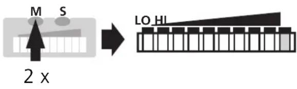 | Press the Mode/Enter button twice. The current setting is indicated (green LED). |
| 2 | 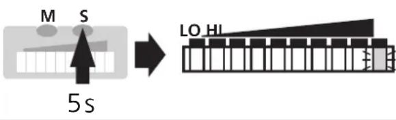 | Press the Learn/Set button for 5s (until LED flashes). |
| 3 | 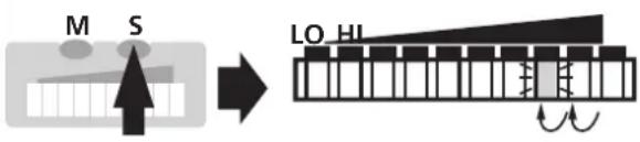 | Press the Learn/Set button several times until the requested LED flashes (LED 8, 7, 6 or 5). Each time the button is pressed the LED moves back by one position. When it is lower than LED 5 the cycle starts again at LED 9. |
| 4 | 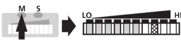 | Press the Mode/Enter button briefly (acknowledgement). The indication goes off briefly. The unit stores the new setting and passes into the run mode. |
Please note:
The display value is reset (to LED 9) after each maximum flow rate adjustment (HI-Teach.
■Activate / deactivate the function for remote adjustment If the function is active, the unit can be adjusted by applying voltage to pin 2.
Unit supplied: function active.
| Function active | 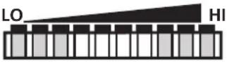 | The 3 LEDs on the right and left are lit in green.* |
| Function not active | 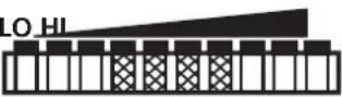 | The 4 LEDs in the middle are lit in red.* |
*The LEDs flash if voltage is applied to pin 2.
| 1 | 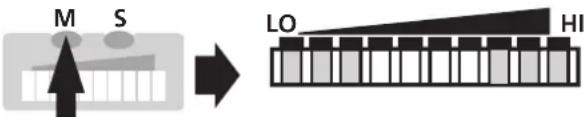 3 x 3 x | Press the Mode/Enter button three times.The current setting is indicated. |
| 2 | 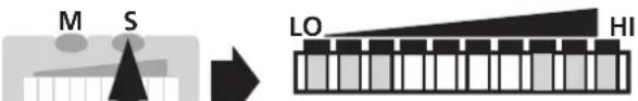 >5s >5s | Press the Learn/Set button and keep it pressed,after 5s the function changes.(Each time the Learn/Set button is pressed the function changes again). |
| 3 | 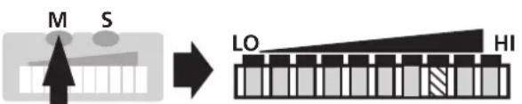 | Press the Mode/Enter button briefly (= acknowledgement).The indication goes off briefly,the unit then passes into the operating mode. |

If the function for remote adjustment is active and the operating voltage is applied to pin 2 for more than 20s, the unit is locked (the buttons are inactive as long as the operating voltage is applied to pin 2).
Use 4-wire connection cables without a link between pins 2 and 4. With 3-wire sockets with a link between pin 2 and pin 4 switching of the output stage triggers the remote adjustment!
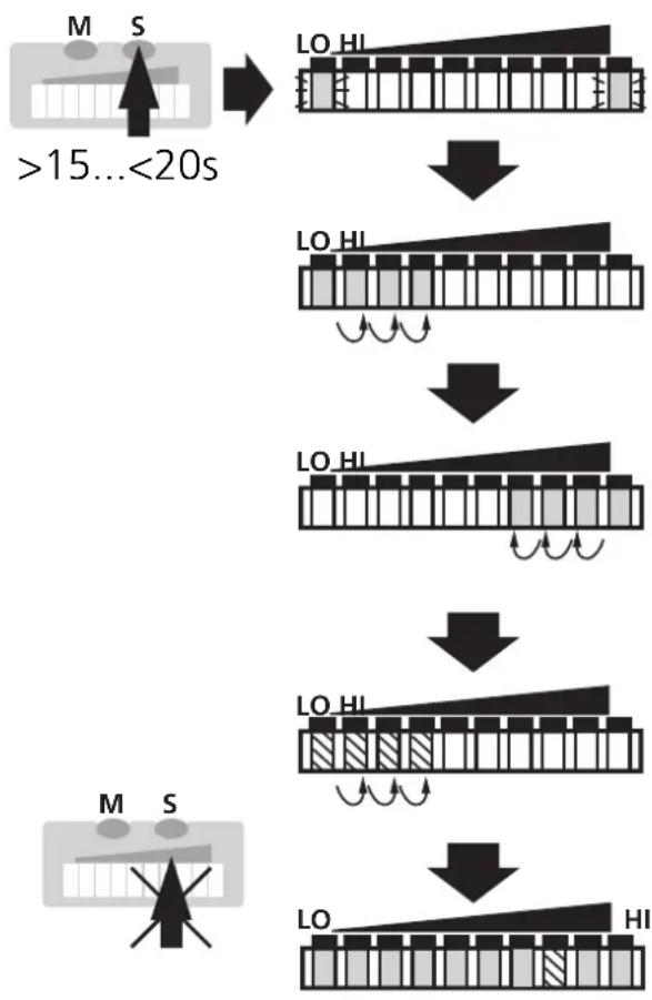
■Return to factory setting
flowchart
graph TD
    A[">15...<20s"] --> B["LO HI"]
    B --> C["LO HI"]
    C --> D["LO HI"]
    D --> E["LO HI"]
    E --> F["LO HI"]
    F --> G["LO HI"]
    G --> H[">15...<20s"]
Press the Learn/Set button and keep it pressed.
The green LEDs on the right and on the left flash,
after 5s the LED bar (green) fills from left to right,
after a further 5s the LED bar (green) fills from right to left,
after a further 5s the LED bar (orange) fills from left to right (release the button as soon as the first orange LEDs light).
The indication goes off briefly. All settings are returned to factory setting and the unit passes into the run mode flow.
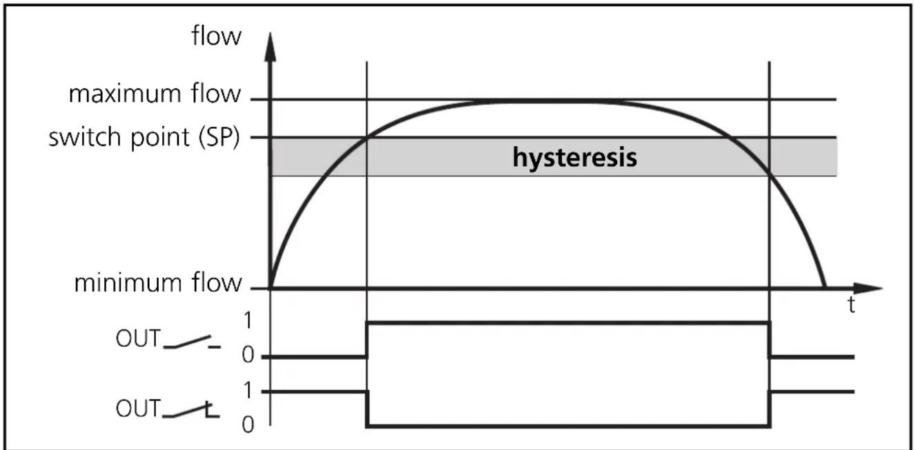
Hysteresis function
line
| Flow Phase | Time (t) | | ------------------ | -------- | | Minimum Flow | 0 | | Maximum Flow | t | | hysteresis | Not labeled | | OUT | 0 | | OUT | 1 |When the flow rises, the output switches when the switch point (SP) has been reached.
When the flow falls again, the output switches back when the value "SP minus hysteresis" has been reached.
The hysteresis is considerably influenced by the choice of the operating range on the sensitivity curve of the sensor:
- In the case of adjustment to HI-Flow values in the range 0 ... 60cm/s the hysteresis is 2 - 4cm/s (values apply to water).
- In the case of adjustment to HI-Flow values above 100cm/s the hysteresis increases as the flow rises.
The typical response time of the unit is 3 ... 8s. It can be influenced by setting the LO-Teach and the switch point:
- The lower the LO-Teach or the switch point is set, the faster the unit switches on.
- The higher the LO-Teach or switch point is set, the faster the unit switches off.
☐ LED = verte LED = orange LED ☒ rouge
natural_image
Pure mechanical component diagram without any text, numbers, or symbols2
natural_image
Technical line drawing of a mechanical assembly with no visible text or symbols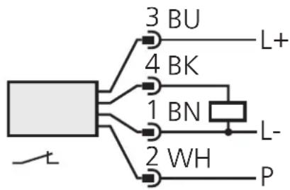
1 = BN (brun), 2 = WH (blanc), 3 = BU (bleu), 4 = BK (noir).

- Kurzanleitung
- - Installieren
- Inhalt
- Brief adjustment instructions
- - Installation
- - HI-Teach
- Further setting options ( → page 27)
- Setting buttons
- Menu structure
- Contents
- Function and features
- Installation
- Electrical connection
- Programming
- ■Setting of the detection range HI-Teach
- Optional: LO-Teach
- ■ Remote adjustment via programming wire
- ■Setting of the switch point
- ■Monitoring excess flow
- ■Activate / deactivate the function for remote adjustment
- ■ Reset to factory settings
- ■The following applies to all setting procedures:
- ■Locking / Unlocking
- Installation and set-up / Operation / Maintenance
- Recommended maintenance
- Technical data
- Programming diagrams / Technical information
- ■Setting of the detection range
- - Adjustment to maximum flow (HI-Teach)
- - Adjustment to minimum flow / flow standstill (LO-Teach), optional
- - Remote adjustment
- ■Return to factory setting
- Hysteresis function
Brand : IFM
Model : SI1001
Category : Detector