JAJ12HSS - Fridge JENN-AIR - Free user manual and instructions
Find the device manual for free JAJ12HSS JENN-AIR in PDF.

User questions about JAJ12HSS JENN-AIR
0 question about this device. Answer the ones you know or ask your own.
Ask a new question about this device
Download the instructions for your Fridge in PDF format for free! Find your manual JAJ12HSS - JENN-AIR and take your electronic device back in hand. On this page are published all the documents necessary for the use of your device. JAJ12HSS by JENN-AIR.
USER MANUAL JAJ12HSS JENN-AIR
natural_image
Architectural line drawing of a double-door refrigerator with open doors and internal compartments (no text or symbols)
JENNAIR®
Your safety and the safety of others are very important.
We have provided many important safety messages in this manual and on your appliance. Always read and obey all safety messages.

This is the safety alert symbol.
This symbol alerts you to potential hazards that can kill or hurt you and others.
All safety messages will follow the safety alert symbol and either the word "DANGER" or "WARNING."
These words mean:
DANGER
You can be killed or seriously injured if you don't immediately follow instructions.
WARNING
You can be killed or seriously injured if you don't follow instructions.
All safety messages will tell you what the potential hazard is, tell you how to reduce the chance of injury, and tell you what can happen if the instructions are not followed.
IMPORTANT SAFETY INSTRUCTIONS
WARNING: To reduce the risk of fire, electric shock, or injury when using your refrigerator, follow these basic precautions:
■ To avoid a hazard due to instability of the appliance, it must be fixed in accordance with the instructions.
■ Plug into a grounded 3 prong outlet.
■ Installation shall be performed only by manufacturer, or an authorized agent.
■ Do not remove ground prong.
■ Do not use an adapter.
■ Do not use an extension cord.
■ Disconnect power to all units before servicing.
■ Replace all parts and panels before operating.
■ Remove doors from your old refrigerator.
■ Use nonflammable cleaner.
■ Do not store or use petrol, flammable liquids or gas in the vicinity of this or other electrical appliances. The fumes can cause fires or explosions.
■ Do not store explosive substances such as aerosol cans with a flammable propellant in this refrigerator.
■ Do not use or place electrical devices inside the refrigerator compartments if they are not of the type expressly authorized by the manufacture.
■ Use two or more people to move and install refrigerator.
■ Disconnect power before installing ice maker (on ice maker kit ready models only).
■ A qualified service technician must install the water line and ice maker. See installation instruction supplied with ice maker kit IC13B for complete details.
■ Connect to a potable water supply only.
■ Use a sturdy glass when dispensing ice (on some models).
■ This appliance is not intended for use by persons (including children) with reduced physical, sensory or mental capabilities, or lack of experience and knowledge, unless they have been given supervision or instruction concerning use of the appliance by a person responsible for their safety.
■ Children should be supervised to ensure that they do not play with the appliance.
■ To avoid the risk of children becoming trapped and suffocating, do not allow them to play or hide inside the refrigerator.
■ If the supply cord is damaged, it must be replaced by the manufacturer, its service agent or similarly qualified person in order to avoid a hazard.
■ This refrigerator is intended to be used in household and similar applications such as:
– staff kitchen areas in shops, offices, and other working environments
– farm houses and by clients in hotels, motels, and other residential type environments
– bed and breakfast type environments
– catering and similar non-retail applications
SAVE THESE INSTRUCTIONS
WARNING
Suffocation Hazard
Remove doors from your old refrigerator.
Failure to do so can result in death or brain damage.
Important information to know about disposal of refrigerants:
Dispose of refrigerator in accordance with Federal and Local regulations. Refrigerants must be evacuated by a licensed, EPA certified refrigerant technician in accordance with established procedures.
natural_image
Line drawing of a closed book with a lid and spines, no text or symbols presentIMPORTANT: Child entrapment and suffocation are not problems of the past. Junked or abandoned refrigerators are still dangerous – even if they will sit for "just a few days." If you are getting rid of your old refrigerator, please follow these instructions to help prevent accidents.
Before You Throw Away Your Old Refrigerator or Freezer:
■ Take off the doors.
■ Leave the shelves in place so that children may not easily climb inside.
EASE. SPEED. SAFETY.
With the launch of the first ever JennAir ^® columns, we reimagined the entire columns installation process, eliminating problems that affect our sub-par competitors. Some of the features professional installers are most excited about:
- Concealed six-point panel adjustment
Easy and precise alignment
- Site-tailored Rotter system shims and badass bracket
Guide and keep column in position
- Precision four-point front leveling
On sturdy rollers that easily bear full weight
- Metal fascia
Increases durability
• Solid wood core stainless steel panels
Easy to prep and hang and do not require drilling through steel
- Expanded utility areas
Reduced changes to replace built-ins or upgrade from competitor columns
And with your help, we'll just keep getting better.
Contact the JennAir Epicenter through jennair.com or at 1-800-JENNAIR (536-6247)
to report installation tips and tricks, or to consult with experts who know
the installation process inside and out.
WHY WE LOVE
JENNAIR INSTALLERS
THEY'RE TOTAL PROFESSIONALS (AND PERFECTIONISTS).
It's all about getting that seamless flush execution, that down-to-the-millimeter adjustment. Flawless installation is incredibly important to the function, appearance and lifetime enjoyment of our products, and our installers make it happen every day.
THEY DO THEIR HOMEWORK. AND HELP US WITH OURS.
These experts know JennAir ^® products inside and out. They train extensively on JennAir installation, learning the latest techniques and insider tips so they can install our cutting edge appliances with ease. And we value their input, incorporating installer feedback to refine and perfect our installations.
THEY THINK THROUGH EVERY DETAIL OF THE EXPERIENCE.
Above and beyond dedication is the baseline. The JennAir experience starts the minute an installer brings the customer's column home. Keeping the site spotless, taking extreme care with both the appliances and the home and providing an unforgettable introduction to columns is all part of the game plan.
TABLE OF CONTENTS
INTRODUCTION
02 SAFETY INSTRUCTIONS
06 TOOLS & PARTS
08 JOIN KITS
11 CONFIGURATIONS
13 PRODUCT DIMENSIONS
15 DOOR STYLE
16 OPENING DIMENSIONS
21 SITE PREP
24 INSTRUCTION KEY
PREPARATION
25 SECTION 1 // PREPARE COLUMNS
32 SECTION 2 // PREPARE JOIN KIT
37 SECTION 3 // PREPARE POSITIONING BRACKET
40 SECTION 4 // BADASS BRACKET INSTALLATION
49 SECTION 5 // PREPARE FURNITURE
INSTALLATION
55 SECTION 6 // FIRST COLUMN INSTALLATION
65 SECTION 7 // SECOND COLUMN INSTALLATION
73 SECTION 8 // THIRD COLUMN INSTALLATION
81 SECTION 9 // PREPARE COLUMN FOR USE
ACCESSORIES
87 SECTION 10 // TOE-KICK: CUSTOM WOOD PREPARATION
90 SECTION 11 // TOE-KICK: STAINLESS STEEL PREPARATION
93 SECTION 12 // TOE-KICK: ALIGN AND INSTALL
98 SECTION 13 // PANEL: CUSTOM WOOD PREPARATION
103 SECTION 14 // PANEL: STAINLESS STEEL PREPARATION
106 SECTION 15 // PANEL: IIANG AND ALIGN
COMPLETE
113 SECTION 16 // COMPLETE INSTALLATION
116 FINAL CHECKLIST
120 TABLE DES MATIÈRES
TOOLS + PARTS
PROVIDED
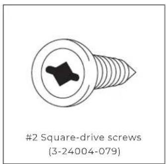
text_image
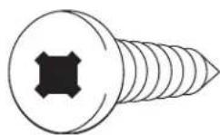
#2 Square-drive screws (3-24004-079)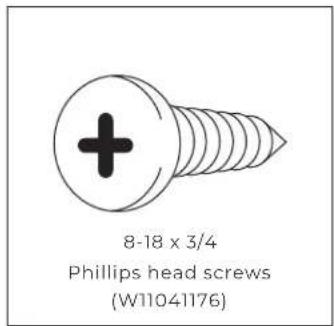
text_image
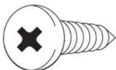
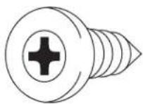
8-18 x 3/4 Phillips head screws (W11041176)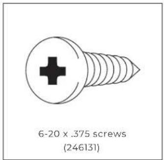
text_image
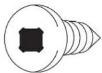
6-20 x .375 screws (246131)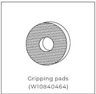
text_image
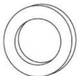
Gripping pads (W10840464)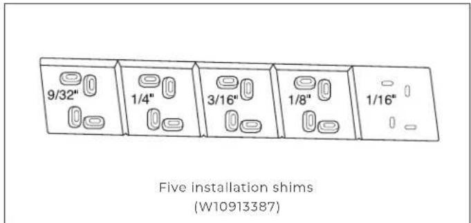
text_image
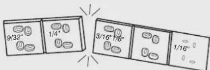
9/32" 1/4" 3/16" 1/8" 1/16" Five installation shims (W10913387)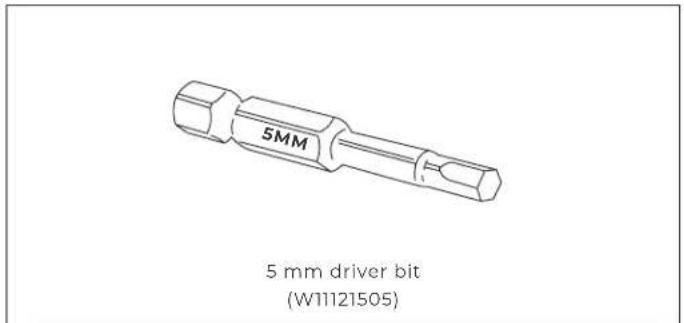
text_image
5MM 5 mm driver bit (W11121505)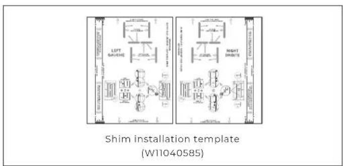
text_image
LEFT BAUCHE RIGHT DRIVE Shim installation template (W11040585)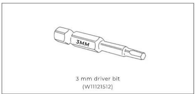
text_image
3MM 3 mm driver bit (W11121512)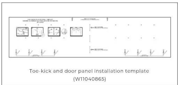
text_image
TOE-KICK AND DOOR PANEL INSTALLATION TEMPLATE (W11040865)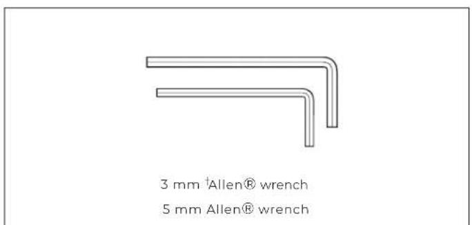
text_image
3 mm †Allen® wrench 5 mm Allen® wrench
READ AND FOLLOW THE INSTRUCTIONS PROVIDED WITH ANY OF THE TOOLS LISTED.
^† ^® Allen is a registered trademark of Apex Brands, Inc.
6 INTRODUCTION
TOOLS + PARTS
NOT PROVIDED
TOOLS
□ Cordless drill and drill bits or impact driver
☐ Drill bit set including 3/32" and 1/8" diameter bits
□ Two adjustable wrenches
□ #2 Phillips bit
☐ 1/4" magnetic nut driver
□ #2 square-drive bit
☐ 48" or longer level or straight edge (Can substitute a factory-installed trim piece, once removed.)
☐ 3/8" and 1/2" open-end wrenches
□ Tape measure
□ Utility knife
□ Masking tape
□ Appliance dolly
☐ Right angle drill adapter
□ 6" drill extension
☐ #8 pan head wood screws of assorted lengths including 1", 1-1/4", 1-1/2"
PARTS
☐ Flexible code-approved water supply line
□ Custom door overlay panels
• Stainless steel panels: order from JennAir
- Custom wood panels: consult a qualified cabinetmaker or carpenter
☐ Additional fasteners will be required according to the kitchen furniture construction
WHY USE
ROTTER
SYSTEM
SHIMS
AND THE
BADASS
BRACKET?
This recommended process might be unfamiliar to
you as an installer, but it adds enormous value to both
you and your client. Use the Rotter system to:
• Help position column without scratching
- Create precise 1/8" reveals on each side
• Always have ready-made shims tailored to each site
- Keep column stable in cutout over lifetime
- Eliminate misalignment issues for your client
text_image
9/32" 1/4" 3/16"7/8" 1/16"JOIN KITS
SOLD SEPERATELY
natural_image
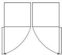
Pure geometric diagram with four rectangles and curved lines, no text or symbols presentHandle-to-handle join kit (JAJ13HSS)
natural_image
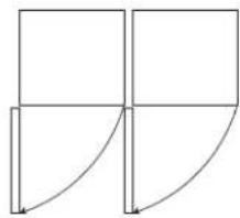
Pure geometric diagram with lines and arrows, no text or symbols presentHandle-to-hinge join kit (JAJ11HSS)
natural_image
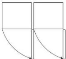
Pure geometric diagram with four squares and curved arrows, no text or symbols presentHinge-to-handle join kit (JAJ12HSS)
natural_image
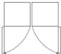
Pure geometric diagram with four squares and curved lines, no text or symbols presentBurlesque Handle-to-handle join kit (JAJ14JSS)
TOOLS AND PARTS INCLUDED IN JOIN KITS
10-13 x 2.0 FL CR
10-13 x PN CR (W1117666)
(17) Flat washers (8534057)
8-18 x MFI 6L HL SS BLK (W1117377)
Join kit spacer (W1111782)

READ AND FOLLOW THE INSTRUCTIONS PROVIDED WITH ANY OF THE TOOLS LISTED.
JOIN KITS
SOLD SEPERATELY
TOOLS AND PARTS INCLUDED IN JOIN KITS (CONTD.)
natural_image
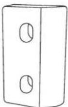
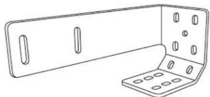
Line drawing of a metal bracket with two circular holes (no text or symbols)Positioning bracket mount (W1111772)
(14) 8-15 x "L" Mtr cr cone screws (8281252)
natural_image
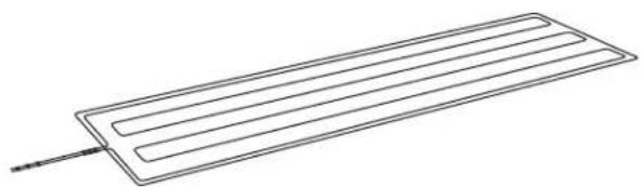
Simple line drawing of a rectangular electronic component with parallel leads and a pointer (no text or symbols)Peel and stick heating pad (W10912090)
(8) M6-1 x 610 mm metric hex nuts (W10854505)

Soffit bracket installation template (W11040584)
natural_image
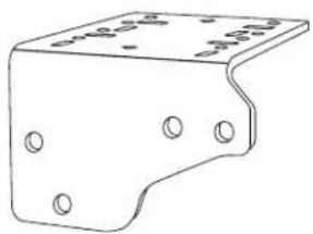
Technical line drawing of a metal bracket with mounting holes (no text or symbols)Badass soffit bracket (W1111754)
natural_image
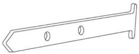
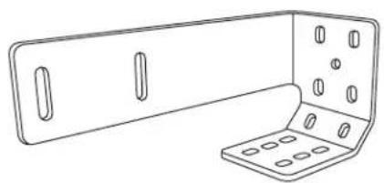
Line drawing of a metal bracket with slots and mounting holes (no text or symbols)Positioning bracket (W1111771)

READ AND FOLLOW THE INSTRUCTIONS PROVIDED WITH ANY OF THE TOOLS LISTED.
JOIN KITS
SOLD SEPERATELY
TOOLS AND PARTS INCLUDED IN JOIN KITS (CONTD.)
Handle-to-handle join kit
| Left-hand (handle) trim(W11103734) |
| Right-hand (handle) trim(W11103737) |
Handle-to-hinge join kit
| Left-hand (handle) trim(W11103734) |
| Right-hand (hinge) trim(W11103736) |
Hinge-to-handle join kit
| Left-hand (handle) trim(W11103737) |
| Right-hand (hinge) trim(W11103735) |
CONFIGURATIONS
2 - UNITS
CAUTION
Pinch Hazard
Installation of door panels with less than a 3/8" (0.95 cm) gap between the door panel and the adjacent cabinet increases the risk of potential pinching.
PERMISSABLE 2-UNIT CONFIGURATIONS
Handle-to-handle
join kit
(JAJ13HSS)
Hinge-to-handle
join kit
(JAJ12HSS)
Handle-to-hinge
join kit
(JAJ11HSS)
natural_image
Simple line drawing of a mechanical support structure with two vertical arms and blue clamps (no text or symbols)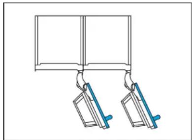
natural_image
Simple line drawing of two hanging objects with blue handles, no text or symbols present
natural_image
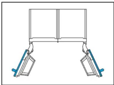
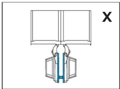
Diagram of two mechanical clamps hanging from a rectangular frame (no text or symbols)NON-PERMISSABLE 2-UNIT CONFIGURATIONS
Hinge-to-hinge
natural_image
Diagram of a mechanical assembly with a blue internal component and a labeled X (no text or symbols on the diagram itself)CONFIGURATIONS
3-UNITS
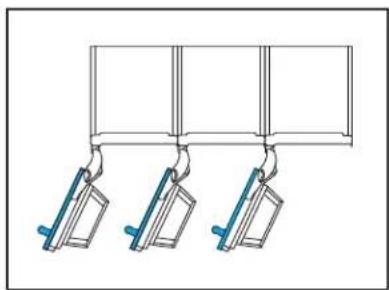
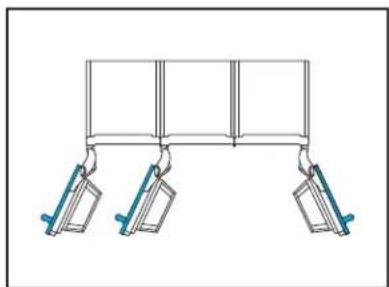
PERMISSABLE 3-UNIT CONFIGURATIONS
Handle-to-hinge and
handle-to-hinge
join kits:
JAJ11HSS (X2)
Hinge-to-handle and
hinge-to-handle
join kits:
JAJ12HSS (x2)
natural_image
Pure diagram of three hanging metal objects with blue connectors, no text or symbols presentHandle-to-hinge and
handle-to-handle
join kits:
JAJ11HSS and JAJ13HSS
natural_image
Pure diagram of three hanging objects with blue handles, no text or symbols presentHandle-to-handle and
hinge-to-handle
join kits:
JAJ13HSS and JAJ12HSS
natural_image
Pure mechanical diagram showing two vertical supports with blue levers, no text or symbols present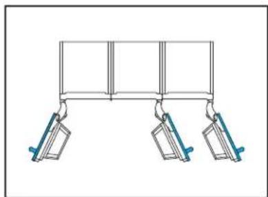
natural_image
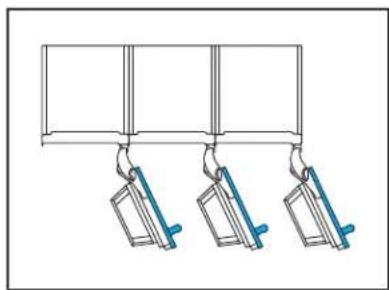
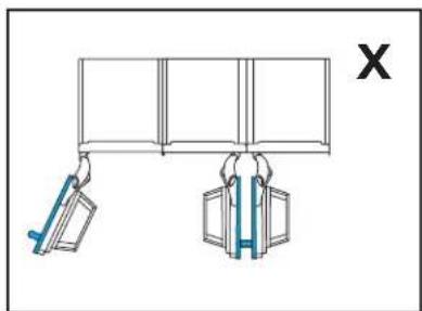
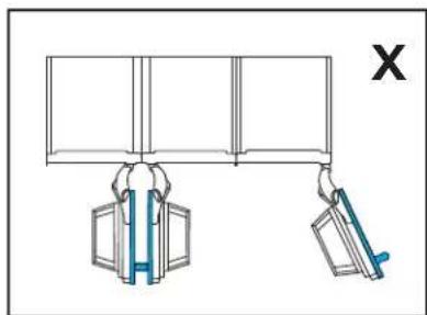
Simple line drawing of a three-panel support structure with hanging weights (no text or symbols)NON-PERMISSABLE 3-UNIT CONFIGURATIONS
Hinge-to-hinge
natural_image
Diagram showing two hanging objects with blue weights, no text or symbols presentHinge-to-hinge
natural_image
Diagram showing two hand gestures lifting a wall-mounted device, with no text or symbols present.DIMENSIONS
PRODUCT
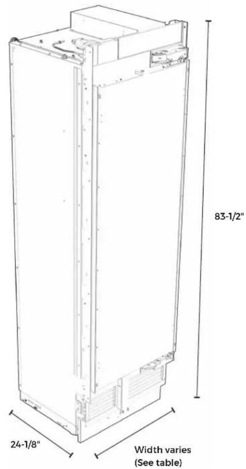
OVERALL PRODUCT (NO PANEL)
| Width See unit width table below | |
| Height 79-7/8" – 85-5/16" (202.9 – 215.9 cm) | |
| Depth 24-1/8" (61.3 cm) | |
| Raw Door Height 79-7/8" (202.9 cm) | |
| Toe-kick Height 3-9/16" (9.1 cm) | |
| Toe-kick Depth 3-1/4" – 4-7/8" (8.3 – 12.4 cm) |
PRODUCT WIDTH
| Model Width | |
| 18"JBZFR18IGXJBZFL18IGXALOVE18FL | 17-3/4"(45.1 cm) |
| 24"JBRFR24IGXJBRFL24IGXJBZFR24IGXJBZFL24IGXALOVE24FLALOVE24RR | 23-3/4"(60.3 cm) |
| 30"JBRFR30IGXJBRFL30IGXJBZFR30IGXJBZFL30IGXALOVE30RR | 29-3/4"(75.6 cm) |
| 36"JBRFR36IGXJBRFL36IGX | 35-3/4"(90.8 cm) |
text_image
83-1/2" 24-1/8" Width varies (See table)DIMENSIONS
ACCESSORIES
STAINLESS STEEL PANEL
| Height 80" (203.2 cm) | |
| Thickness 13/16" (2.1 cm) |
CUSTOM TOE-KICK
| Height 3-9/16" (9.1 cm) | |
| Thickness 3/16"-3/4" (4.8 – 1.9 mm) | |
CUSTOM PANEL
| Thickness 3/4" (1.9 cm) max. |
| Weight 60 lbs. (27.2 kg) max. |
| Typical Height 80" (203.2 cm) |
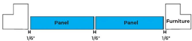
DOOR STYLE
CUSTOM PANEL WIDTH
CAUTION
Pinch Hazard
Installation of door panels with less than a 38 " (0.95 cm) gap between the door panel and the adjacent cabinet increases the risk of potential pinching.
MODEL FLUSH WIDTH
| 18" 17-3/4" (45.1 cm) |
| 24" 23-3/4" (63.5 cm) |
| 30" 29-3/4" (75.6 cm) |
| 36" 35-3/4" (90.8 cm) |
MODEL OVERLAY WIDTH
| 18" 18-3/8" (46.7 cm) |
| 24" 24-3/8" (61.9 cm) |
| 30" 30-3/8" (77.2 cm) |
| 36" 36-3/8" (92.4 cm) |
text_image
Panel Panel Furniture 1/6" 1/6" 1/6"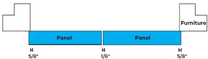
text_image
Furniture Panel Panel H H H 5/8" 1/6" 5/8"MODEL FLUSH WIDTH
| 18" 17-3/4" (45.1 cm) |
| 24" 23-3/4" (63.5 cm) |
| 30" 29-3/4" (75.6 cm) |
| 36" 35-3/4" (90.8 cm) |

flowchart
graph LR
    A[" "] --> B["Panel"]
    B --> C[" "]
    C --> D["PanelPanel"]
    D --> E["Furniture"]
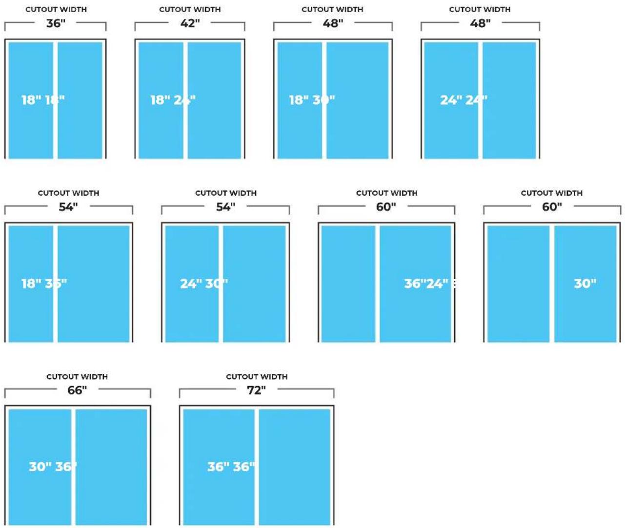
DIMENSIONS
OPENING
2-UNIT CONFIGURATIONS
NOTE: These diagrams show cutout width of product combinations.
Products may be arranged into any permissible configuration shown on pg. 10-11.
DIMENSIONS
OPENING
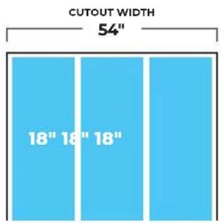
3-UNIT CONFIGURATIONS
NOTE: These diagrams show cutout width of product combinations.
Products may be arranged into any permissible configuration shown on pg. 10-11.
text_image
CUTOUT WIDTH 54" 18" 18" 18"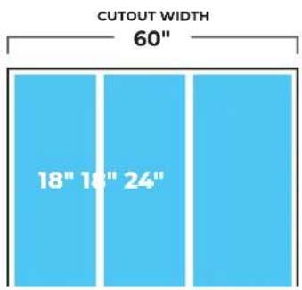
text_image
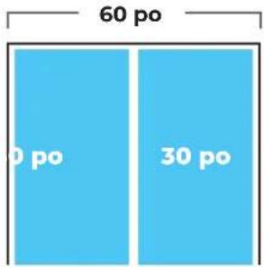
CUTOUT WIDTH 60" 18" 18" 24"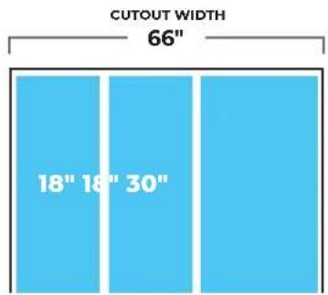
text_image
CUTOUT WIDTH 66" 18" 18" 30"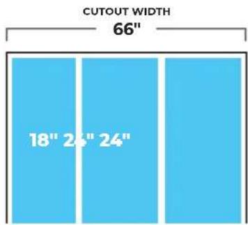
text_image
CUTOUT WIDTH 66" 18" 24" 24"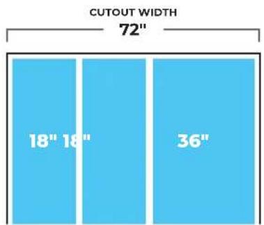
text_image
CUTOUT WIDTH 72" 18" 18" 36"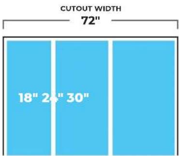
text_image
CUTOUT WIDTH 72" 18" 24" 30"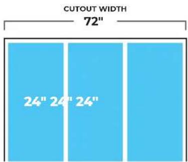
text_image
CUTOUT WIDTH 72" 24" 24" 24"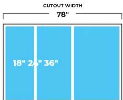
text_image
CUTOUT WIDTH 78" 18" 24" 36"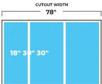
text_image
CUTOUT WIDTH 78" 18" 30" 30"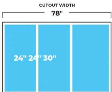
text_image
CUTOUT WIDTH 78" 24" 24" 30"DIMENSIONS
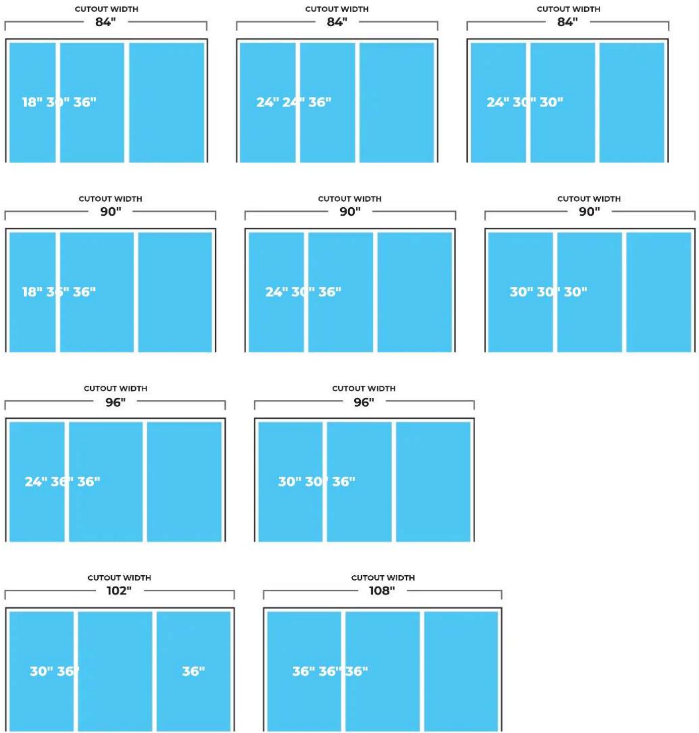
OPENING
3-UNIT CONFIGURATIONS
NOTE: These diagrams show cutout width of product combinations.
Products may be arranged into any permissible configuration shown on pg. 10-11.
DIMENSIONS
OPENING
CAUTION
Pinch Hazard
Installation of door panels with less than a 38 " (0.95 cm) gap between the door panel and the adjacent cabinet increases the risk of potential pinching.
DOOR SWING REQUIREMENTS
| Model 115° Door Swing "A" 90° Door Swing "B" Wall Gap "C" Door Open Depth "D" | ||||
| 18" 10-1/2" (26.7 cm) 5" (12.7 cm) 2-1/2" (6.4 cm) 44-1/2" (113 cm) | ||||
| 24" 13" (33 cm) 5" (12.7 cm) 2-1/2" (6.4 cm) 50-1/2" (128.3 cm) | ||||
| 30" 15-1/2" (39.4 cm) 5" (12.7 cm) 2-1/2" (6.4 cm) 56-3/8" (143.2 cm) | ||||
| 36" 18" (45.7 cm) | 5" (12.7 cm) | 2-1/2" (6.4 cm) | 62-7/16" (158.6 cm) | |
Dimensions give 2-1/2" spacing between stainless steel handle accessory and wall to avoid pinching.
For a custom wood panel, consider handle depth to maintain 2-1/2" spacing.
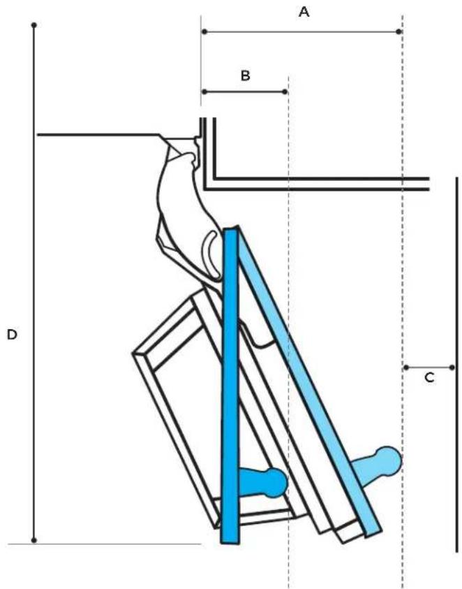
text_image
A B D CDIMENSIONS
OPENING
OPENING WIDTH
| Model Width (A) | |
| 18"JBZFR18IGXJBZFL18IGXALOVE18FL | 18"(45.7 cm) |
| 24"JBRFR24IGXJBRFL24IGXJBZFR24IGXJBZFL24IGXALOVE24FLALOVE24RR | 24"(61 cm) |
| 30"JBRFR30IGXJBRFL30IGXJBZFR30IGXJBZFL30IGXALOVE30RR | 30"(76.2 cm) |
| 36"JBRFR36IGXJBRFL36IGX | 36"(91.4 cm) |
text_image
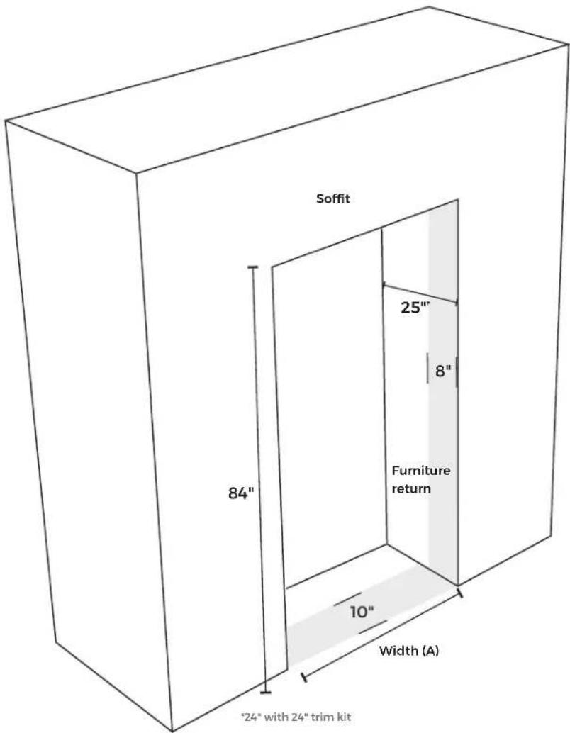
Soffit 84" 25" 8" Furniture return 10" Width (A) "24" with 24" trim kitSITE PREP
1. CHECK THE FURNITURE
☐ Measure to make sure all opening dimensions are correct. (See previous page.)
☐ Side panel construction: 3/4" (1.9 cm) thick plywood.
IMPORTANT: Cannot be constructed of pressed fiber material such as MDF.
☐ Soffit height: 84" (213.4 cm).
☐ A single water supply line may be split 2 or 3 ways to service all columns.
WARNING
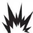
Explosion Hazard
Keep flammable materials and vapors, such as gasoline, away from refrigerator.
Failure to do so can result in death, explosion, or fire.
2. CHECK THE INSTALLATION SITE
□ Away from ovens, radiators or other heat sources.
☐ Temperature will not fall below 55^ F ( 13^ C).
☐ Floor supports more than 600 lbs. (272 kg) plus door panel and contents weight.
☐ Floor level with the room.
□ Furniture face plumb.
text_image
or 3 s , or fire. 1/8" max Side Panel Furniture Return Soffit Side Panel Furniture Return 84" INTRODUCTIONSITE PREP
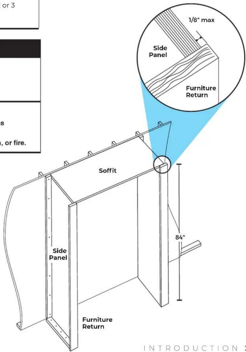
3. CHECK THE WATER SUPPLY
□ Water supply meets local plumbing codes.
☐ Water shutoff in base cabinet, as shown, or accessible area.
☐ Access hole through the cabinet is within 1/2" (1.3 cm) of the rear wall.
☐ Install any additional tubing only where temperatures remain above freezing. Check for leaks.
☐ Not using a piercing-type or 3/16" (4.8 mm) saddle valve. See refrigerator dealer for saddle-type valve kit that complies with local plumbing codes.
☐ If water pressure to reverse osmosis system is less than 40 to 60 psi (276 to 414 kPa):
- Check sediment filter to see if it is blocked. Replace filter if necessary.
- Allow the storage tank to refill after heavy usage.
- Remove the water filter cartridge. No filter bypass is necessary.
WATER SUPPLY REQUIREMENTS
| Water Pressure 30 – 120 psi (207 – 827 kPa) | |
| Water Pressure to Reverse Osmosis System | Minimum 40 – 60 psi(276 – 414 kPa) |
| Excess Water Line for Connection | 30" (76.2 cm) |
| Supply 1/4" OD copper, braided stainless steel or PEX tubing | |
text_image
Water shutoff Access hole (within 1/2" of rear wall)
IF YOU HAVE QUESTIONS ABOUT YOUR WATER SUPPLY, CALL A LICENSED, QUALIFIED PLUMBER.
SITE PREP
WARNING

Electrical Shock Hazard
Plug into a grounded 3 prong outlet.
Do not remove ground prong.
Do not use an adapter.
Do not use an extension cord.
Failure to follow these instructions can result in death, fire, or electrical shock.
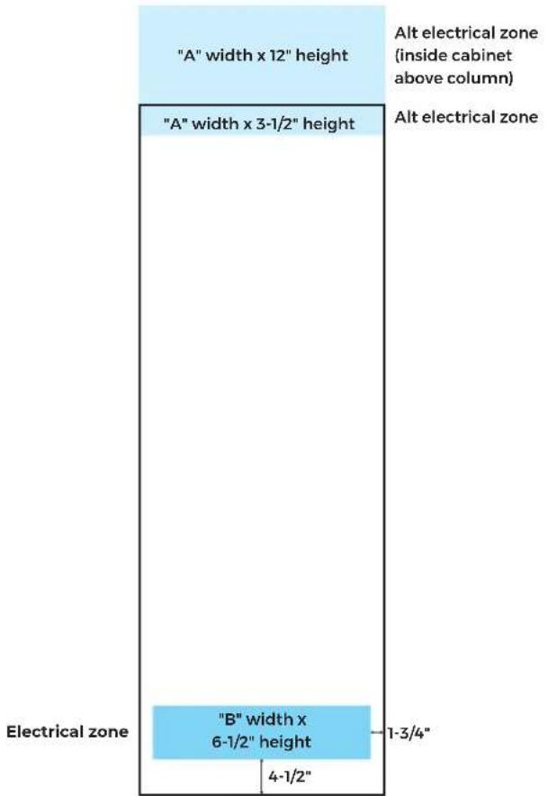
ELECTRICAL REQUIREMENTS
| Product Width/Alternate Electrical Zone Width "A" | Electrical ZoneWidth "B" |
| 18" (45.7 cm) 14-1/2" (36.8 cm) | |
| 24" (60.1 cm) 20-1/2" (52 cm) | |
| 30" (76.2 cm) 26-1/2" (67.3 cm) | |
| 36" (91.4 cm) 32-1/2" (82.6 cm) |
4. CHECK THE ELECTRICAL
☐ Column on a separate circuit. Outlet cannot be turned off by a switch.
□ Not using an extension cord.
□ Not using a GFCI protected outlet.
□ Electrical installed in the zones highlighted. (See graphic to the right.)
text_image
"A" width x 12" height "A" width x 3-1/2" height Alt electrical zone (inside cabinet above column) Alt electrical zone "B" width x 6-1/2" height 4-1/2" 1-3/4" Electrical zone
IF YOU HAVE QUESTIONS ABOUT YOUR ELECTRICAL SUPPLY, CALL A LICENSED, QUALIFIED ELECTRICIAN.
SITE PREP
5. PRE-INSTALLATION CHECK
□ Verify customer's selected door style.
☐ Remove all installation materials from the deli drawer.
☐ Mark selected door style on templates and door depth gauges with a permanent marker.
☐ Verify that the diagonal measurements of opening match.
☐ Check design considerations document to verify panel and toe-kick dimensions, as well as gaps and overlays.
☐ Check for correct join kits based on configuration, left/right side, hinge/non-hinge and installation order.
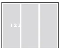
INSTRUCTION KEY
This helpful key tells you where you'll be performing the steps in the following sections. Note that columns are installed and numbered from left to right.
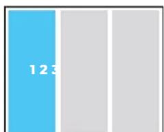
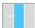
bar
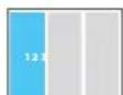
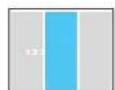
| Category | Value | |---|---| | Blue Bar | 123 |Perform the step on the column highlighted in blue.
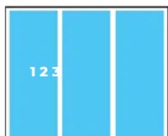
bar
| Category | Value | |---|---| | Top Bar | 12.3 | | Bottom Bar | 3.0 |Perform the step on every column you are installing.
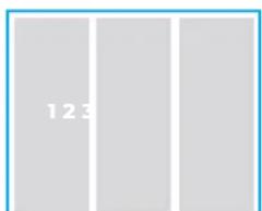
text_image
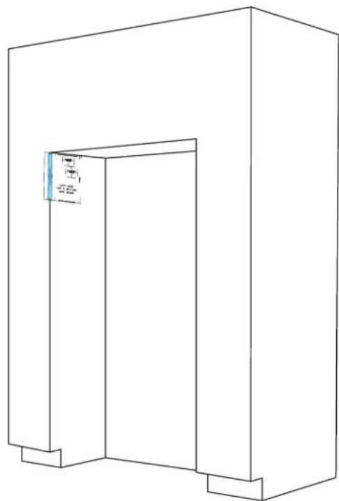
123Perform the step on the furniture.
text_image
123Perform the step on a part that is not attached to a column, such as a door panel or toe-kick.
PRE PAR E
COLUMNS
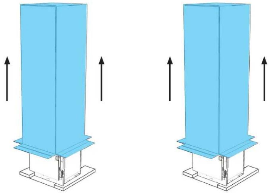
1.1
UNCRATE COLUMNS AND JOIN KITS, DISCARDING CARTONS.
natural_image
Two identical blue industrial structures with upward arrows indicating force or movement, mounted on a base platform (no text or symbols)

REMOVE INSTALLATION KITS FROM DELI DRAWERS WHILE ON SKIDS.
BEFORE MOVING COLUMNS, REVIEW ALL WARNINGS.
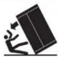
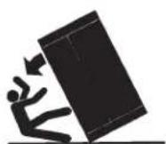
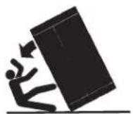
WARNING
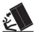
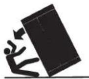
Tip Over Hazard
Refrigerator is top heavy and tips easily when not completely installed.
Keep doors taped closed until refrigerator is completely installed.
Use two or more people to move and install refrigerator.
Failure to do so can result in death or serious injury.
When Moving Your Refrigerator:
Your refrigerator is heavy. When moving the refrigerator for cleaning or service, be sure to cover the floor with cardboard or hardboard to avoid floor damage. Always pull the refrigerator straight out when moving it. Do not wiggle or "walk" the refrigerator when trying to move it, as floor damage could occur.
Important information to know about glass shelves and covers:
Do not clean glass shelves or covers with warm water when they are cold. Shelves and covers may break if exposed to sudden temperature changes or impact, such as bumping. Tempered glass is designed to shatter into many small, pebble-size pieces. This is normal. Glass shelves and covers are heavy. Use both hands when removing them to avoid dropping.
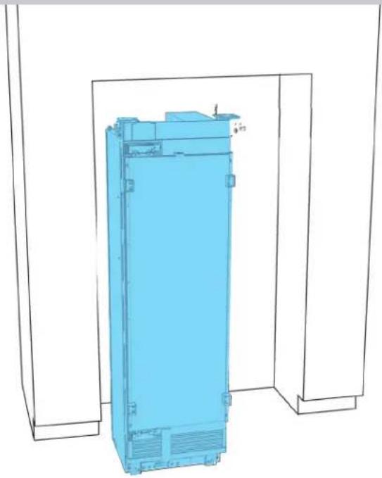
1.2
EACH COLUMN: MOVE IN FRONT OF OPENING.
natural_image
3D wireframe diagram of a blue industrial cabinet or enclosure with mounting brackets (no text or symbols)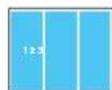

USE TWO PEOPLE. DO NOT OPEN DOORS UNTIL COLUMN IS SECURED.
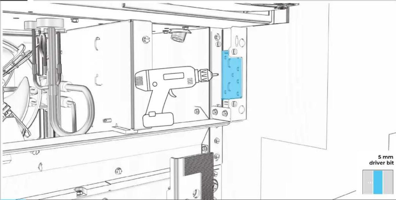
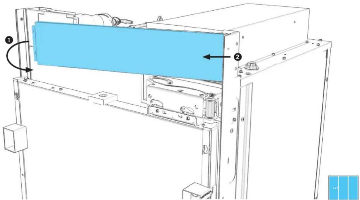
1.3
EACH COLUMN: REMOVE BOTH WATER FILTER SCREWS.
text_image
5 mm driver bit 121.4
EACH COLUMN: PULLING LEFT, REMOVE FACEPLATE.

text_image
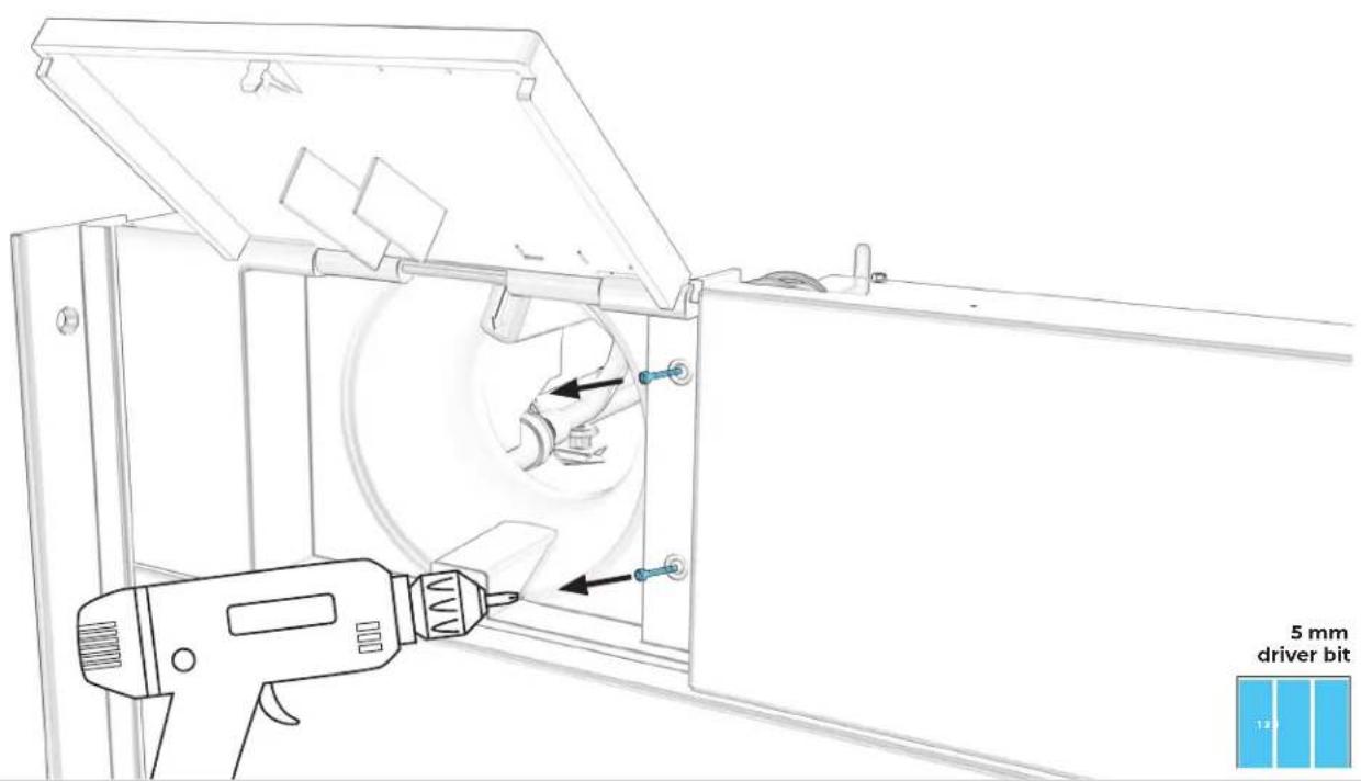
Technical diagram of a mechanical assembly with labeled components and directional arrows indicating motion or flow.1.5
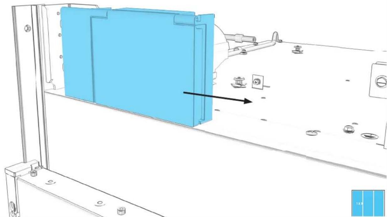
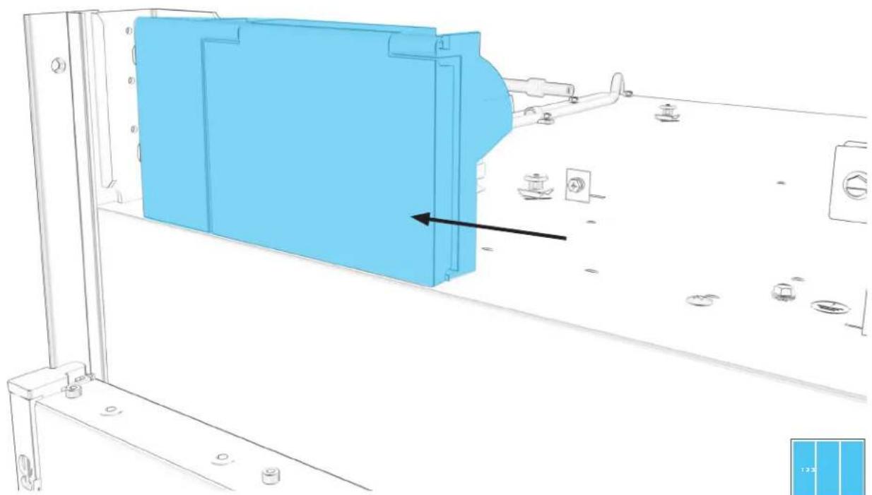
EACH COLUMN: PULL HOUSING FORCEFULLY RIGHT, REMOVE.
natural_image
Technical line drawing of a mechanical assembly with blue panel and mounting fixtures (no text or symbols)1.6
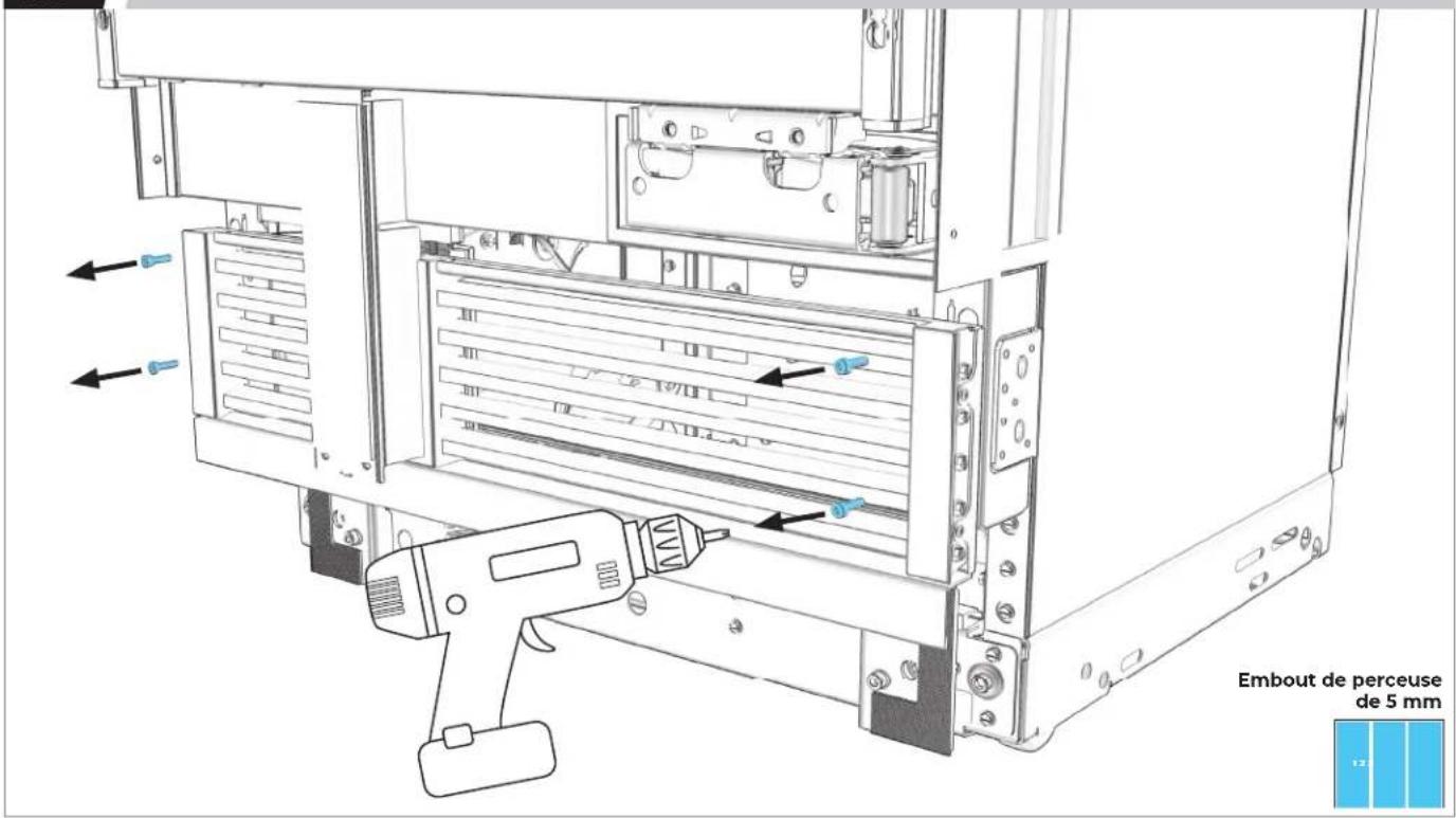
EACH COLUMN: REMOVE FOUR AIR GRILLE SCREWS.
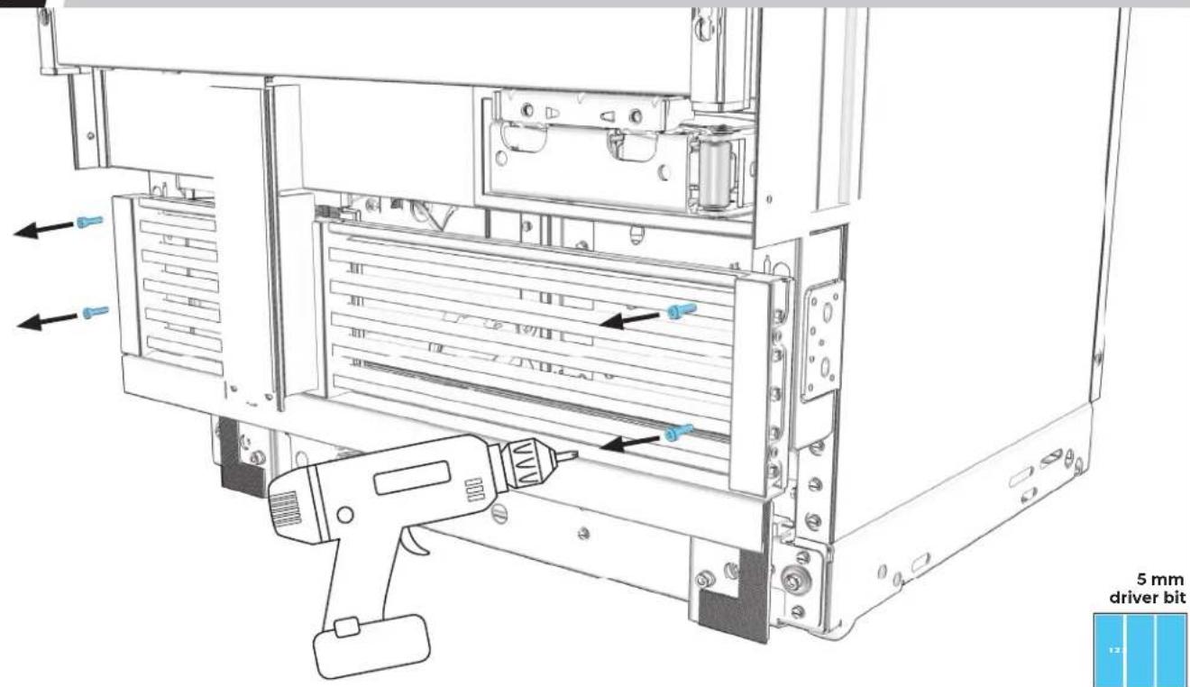
text_image
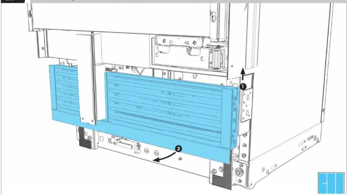
5 mm driver bit1.7
EACH COLUMN: REMOVE BASE AIR GRILLE.
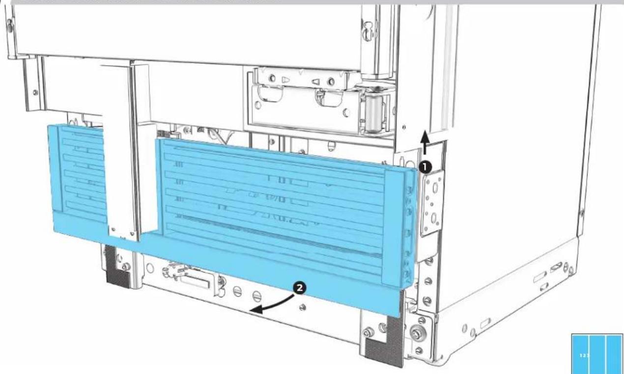
text_image
Technical diagram of a server rack with labeled components and directional arrows indicating assembly or movement.1.8
SECOND (AND THIRD, IF APPLICABLE) COLUMN: INSTALL AIR GRILLE TRIM.
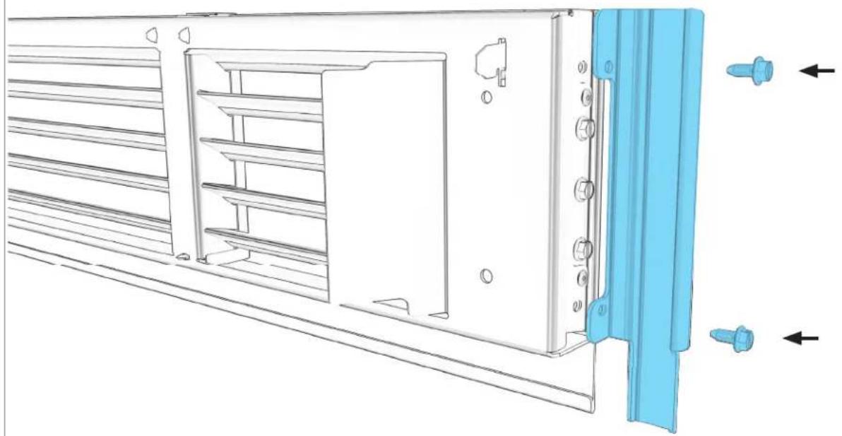
natural_image
Technical line drawing of a server rack with blue plastic components and directional arrows indicating movement (no text or symbols)Phillips head screwdriver

1.9
REMOVE TRIMS BETWEEN COLUMNS.
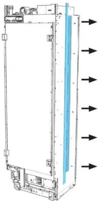
natural_image
Technical line drawing of a server rack with directional arrows indicating flow or movement (no text or symbols present)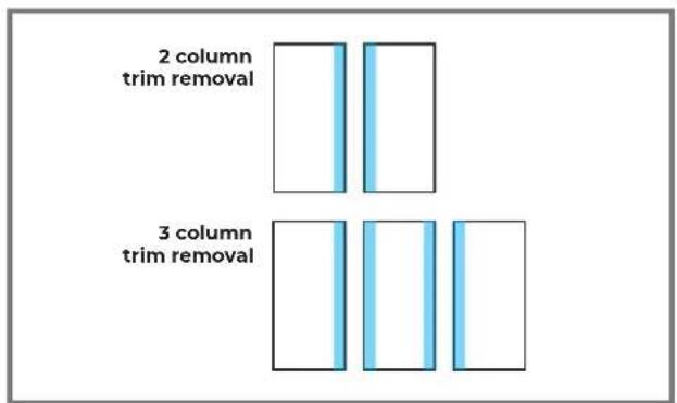
text_image
2 column trim removal 3 column trim removal

LEAVE TRIMS IN PLACE ON FURNITURE SIDES.
1.10
FIRST COLUMN: INSTALL SPACER.
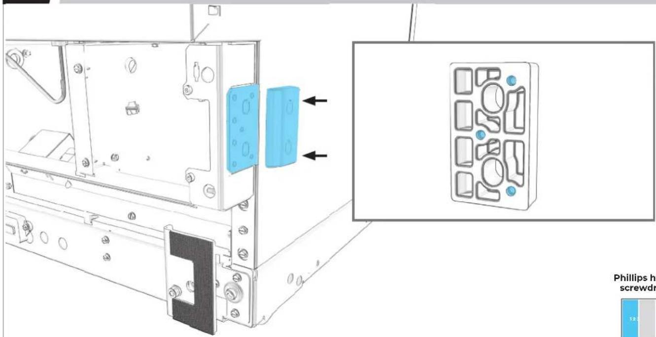
text_image
Phillips h screwdr 12.5Phillips head screwdriver


MAKE SURE NARROW EDGE FACES OUT.
1.11
IF INSTALLING THREE COLUMNS: REPEAT 1.10 ON SECOND COLUMN.
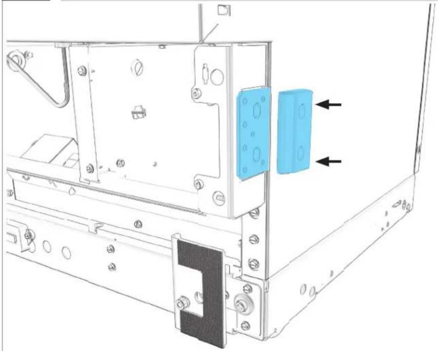
natural_image
Technical line drawing of a mechanical assembly with mounting brackets and a blue component (no text or symbols)Phillips head screwdriver
PRE PAR E
JOIN KIT
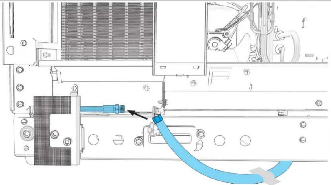
2.1
FIRST COLUMN: ALIGN AND ADHERE HEATER.
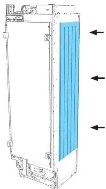
natural_image
Technical line drawing of a rectangular device with internal blue panel and directional arrows indicating flow or movement (no text or symbols)
2.2
PLUG HEATER INTO COLUMN.
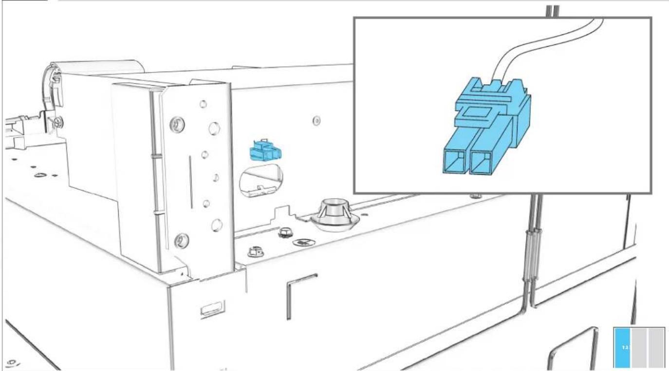
natural_image
Technical line drawing of a mechanical assembly with blue plastic components and a close-up inset showing a connector (no text or symbols)2.3
REPEAT 2.1-2.2 ON SECOND COLUMN.
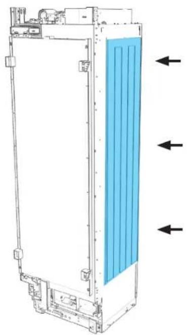
natural_image
Technical line drawing of a vertical industrial or cooling unit with blue insulation material, showing internal components and directional arrows (no text or symbols)
natural_image
Blue plastic electrical connector with two ports and a coiled cable (no text or symbols)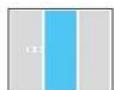
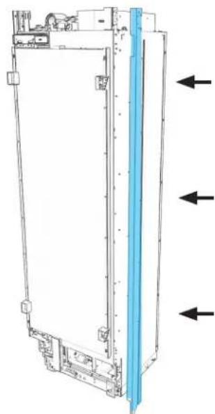
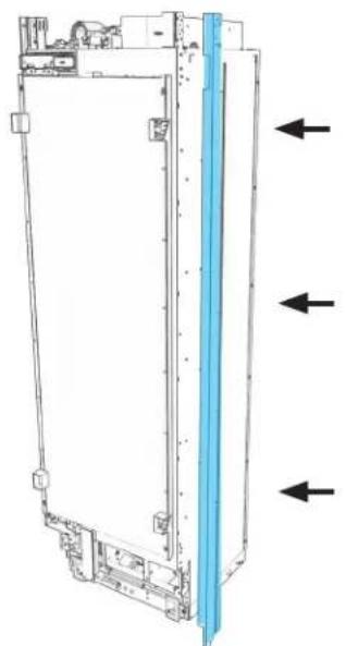
2.4
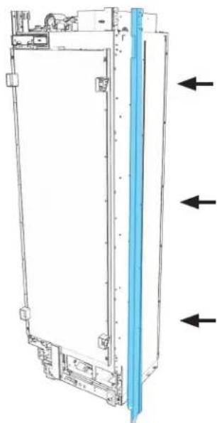
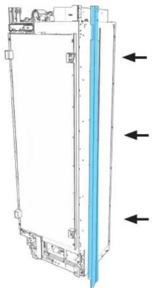
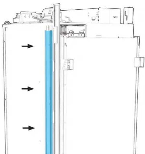
FIRST COLUMN: INSTALL "L" JOIN TRIM.
natural_image
Technical line drawing of a vertical mechanical or electronic component with three arrows indicating direction (no text or symbols present)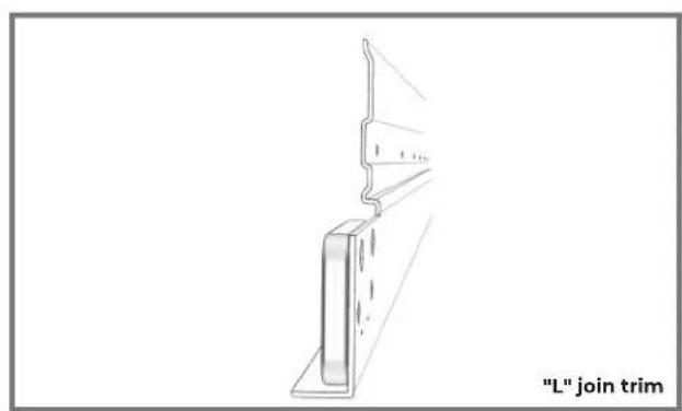
natural_image
Technical line drawing of a structural bracket with a label "L" join trim (no other text or symbols)Phillips head screwdriver

2.5
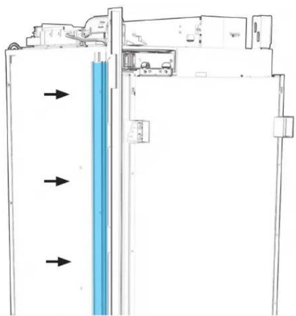
SECOND COLUMN: INSTALL "HOOK" JOIN TRIM.

natural_image
Diagram of a refrigerator interior with blue vertical panel and directional arrows indicating flow or movement (no text or symbols)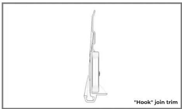
natural_image
Line drawing of a hook join trim device (no text or symbols on the diagram itself)Phillips head screwdriver
2.6
IF INSTALLING THREE COLUMNS: INSTALL "L" JOIN TRIM ON SECOND COLUMN.
natural_image
Technical line drawing of a mechanical device with directional arrows indicating movement or force (no text or symbols present)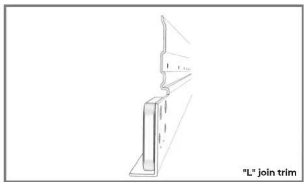
text_image
"L" join trimPhillips head screwdriver
2.7
IF INSTALLING THREE COLUMNS: INSTALL "HOOK" JOIN TRIM ON THIRD COLUMN.

natural_image
Diagram of a refrigerator interior with blue vertical panel and directional arrows indicating flow or movement (no text or symbols)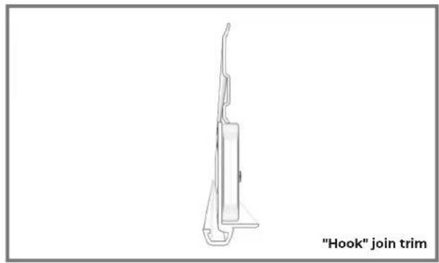
natural_image
Line drawing of a hook join trim device (no text or symbols on the diagram itself)Phillips head screwdriver

PRE PAR E
POSITIONING BRACKET
3.1
FIRST COLUMN: SLIDE MOUNT INTO INSTALLATION SLOT.
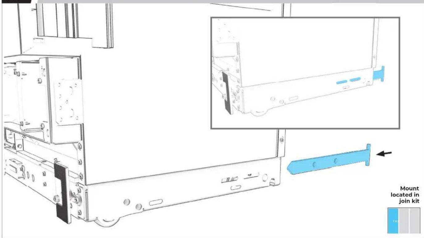
text_image
Mount located in join kit3.2
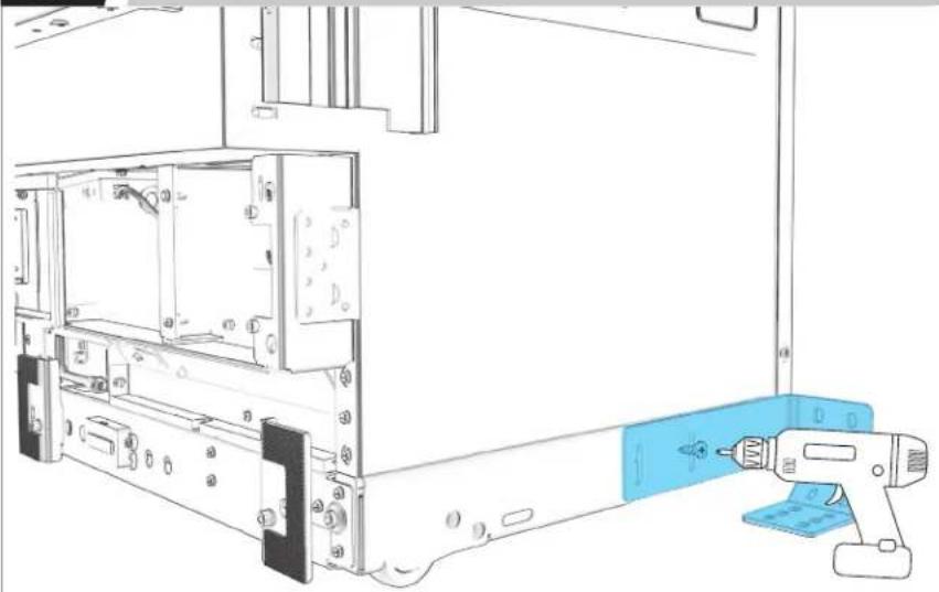
USE SCREWDRIVER TO ENSURE HOLES ARE ALIGNED.
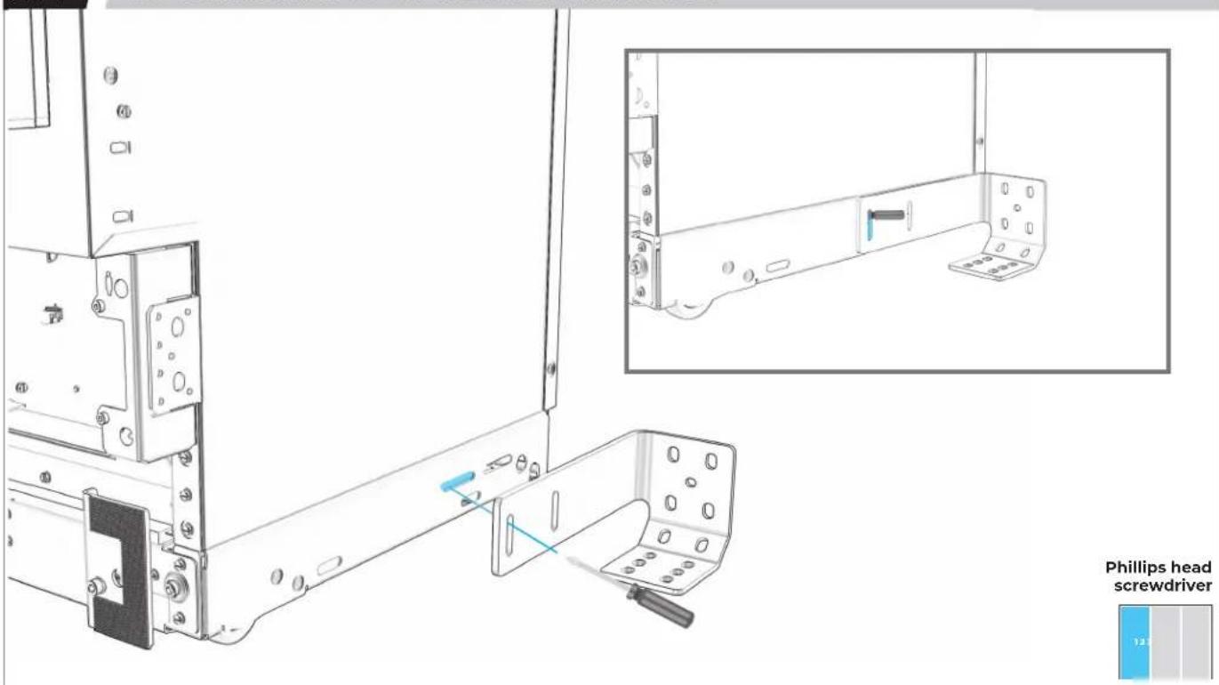
text_image
Phillips head screwdriver3.4
LOOSELY ATTACH POSITIONING BRACKET TO MOUNT.
natural_image
Technical line drawing of a computer monitor internal structure with a blue handheld device inserted (no text or symbols)M6 socket

FINAL PLACEMENT DETERMINED ONCE COLUMNS ARE FULLY RAISED.
3.5
IF INSTALLING A THIRD COLUMN: REPEAT 3.1-3.4 ON SECOND COLUMN.
natural_image
Technical line drawing of a computer monitor with an open rear panel and a blue handheld device inserted (no text or symbols)M6 socket
BADASS
BRACKET INSTALLATION
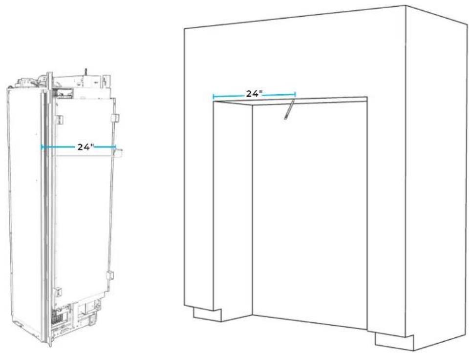
4.1
MARK LINE AT FIRST COLUMN'S WIDTH FROM LEFT-SIDE FACE FRAME.
text_image
24" 24"
4.2
WITH CARPENTER SQUARE, DRAW LINE PERPENDICULAR TO FACE FRAME.
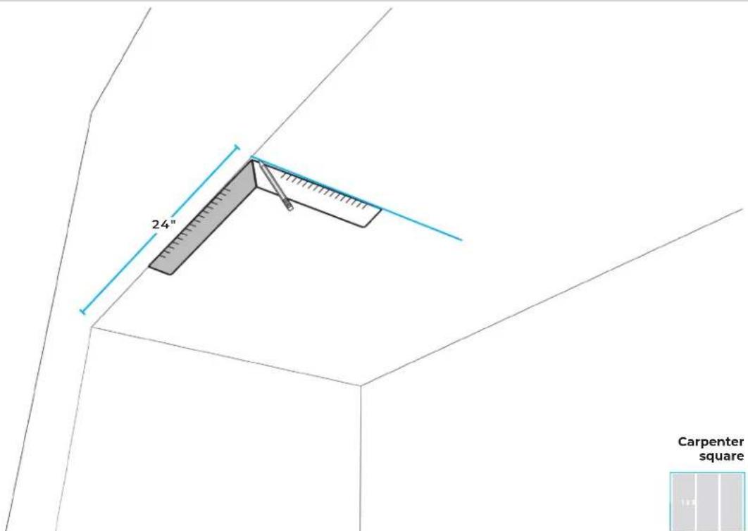
text_image
24" Carpenter square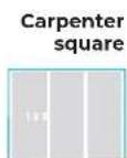
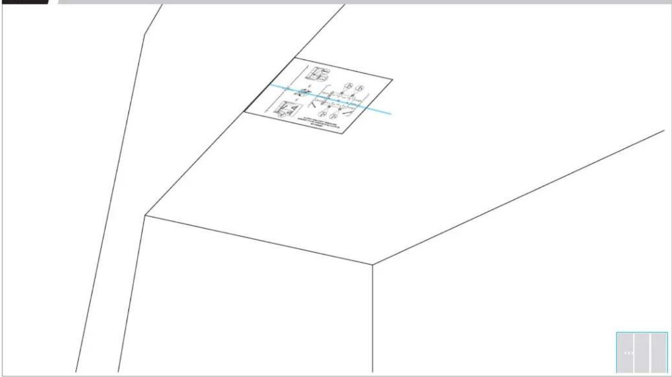
4.3
ALIGN BRACKET TEMPLATE CENTER SLOTS WITH WIDTH LINE.
text_image
Technical drawing with dimension annotations and a labeled diagram box showing geometric relationships4.4
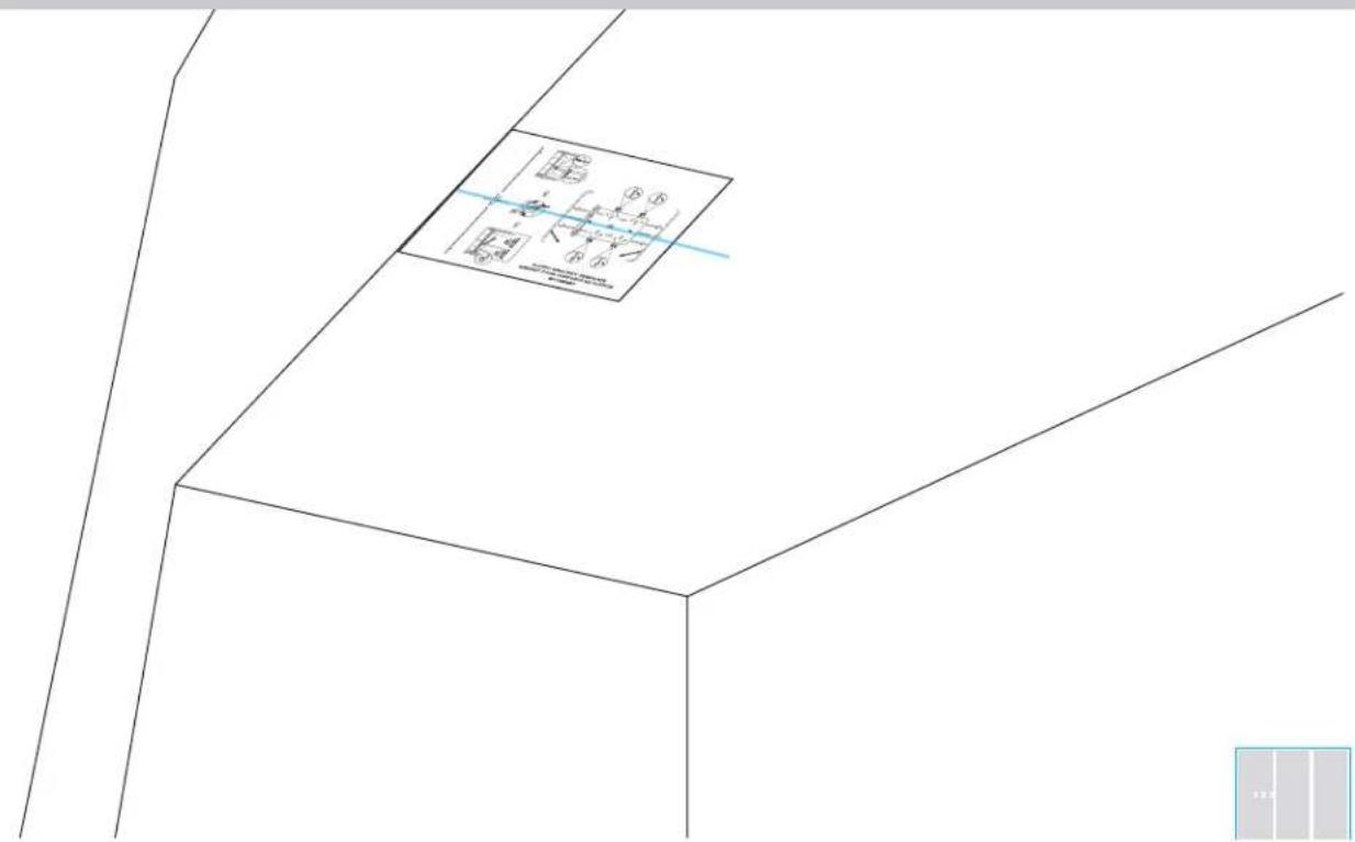
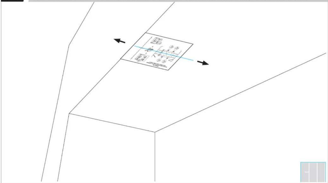
ALIGN THE PREVIOUSLY SELECTED DOOR STYLE LINE WITH CABINET FACE.
text_image
Technical diagram showing a 3D coordinate system with labeled axes and a magnified inset of a rectangular object.4.6
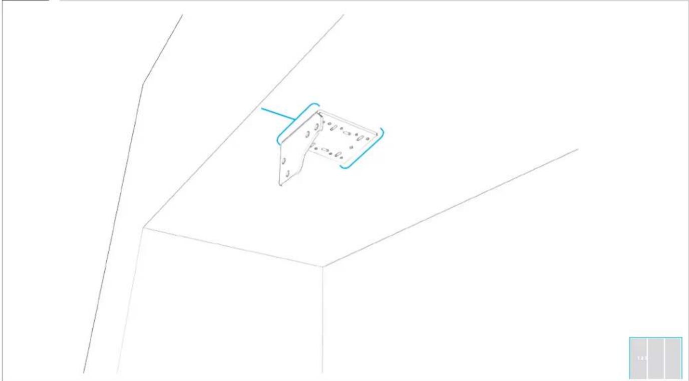
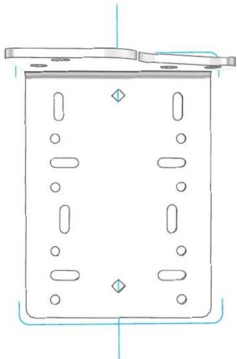
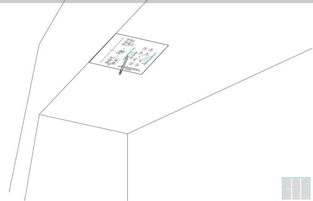
ALIGN BRACKET.
natural_image
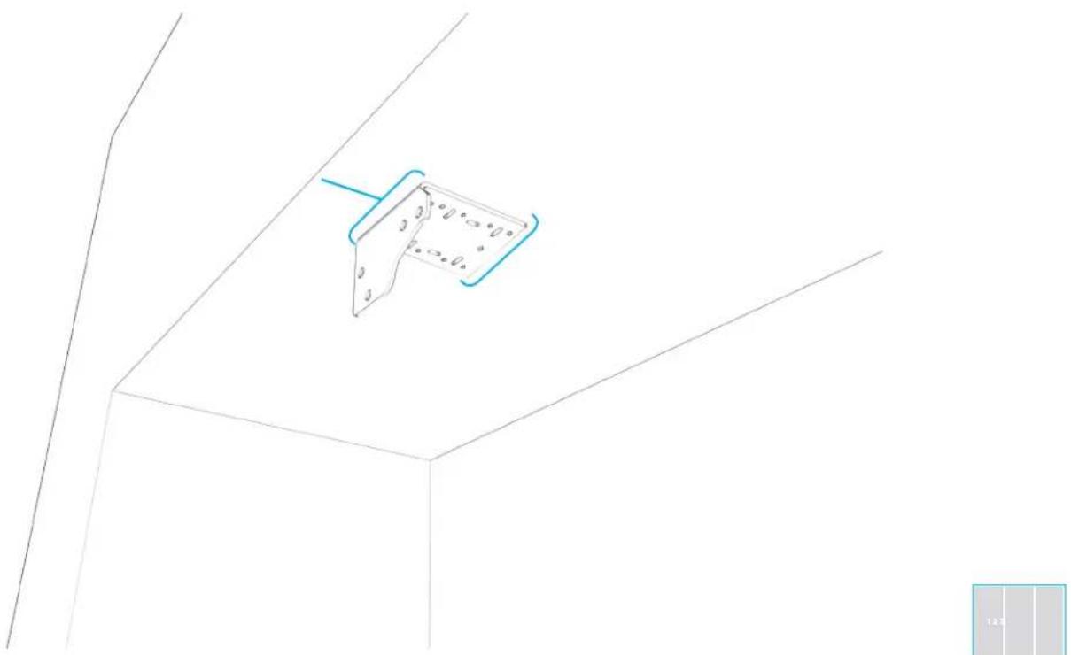
Pure technical line drawing of a 3D mechanical part with no text, numbers, or symbols4.7
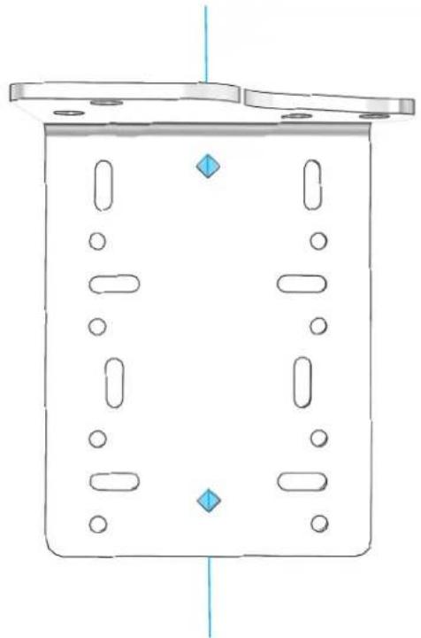
ALIGN POINTS OF DIAMOND-SHAPED HOLES WITH WIDTH LINE.
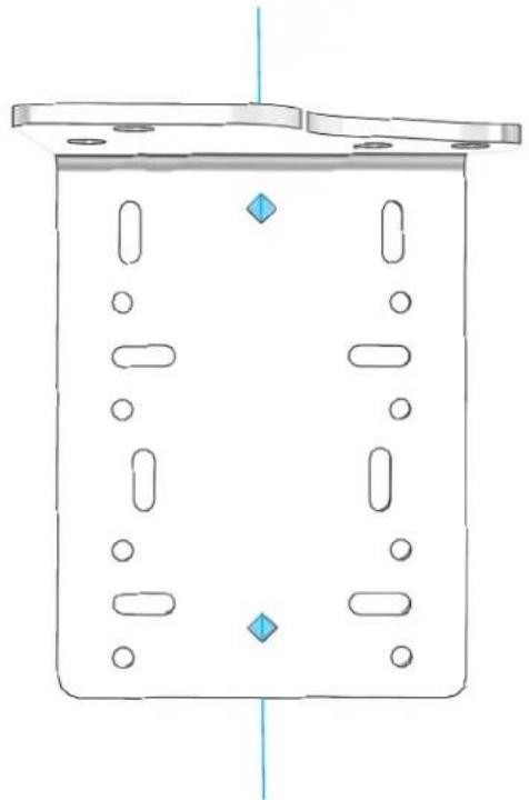
natural_image
Pure technical diagram of a rectangular container with internal compartments and circular holes, no text or symbols present
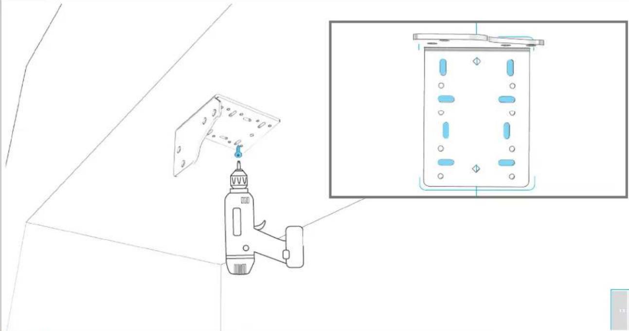
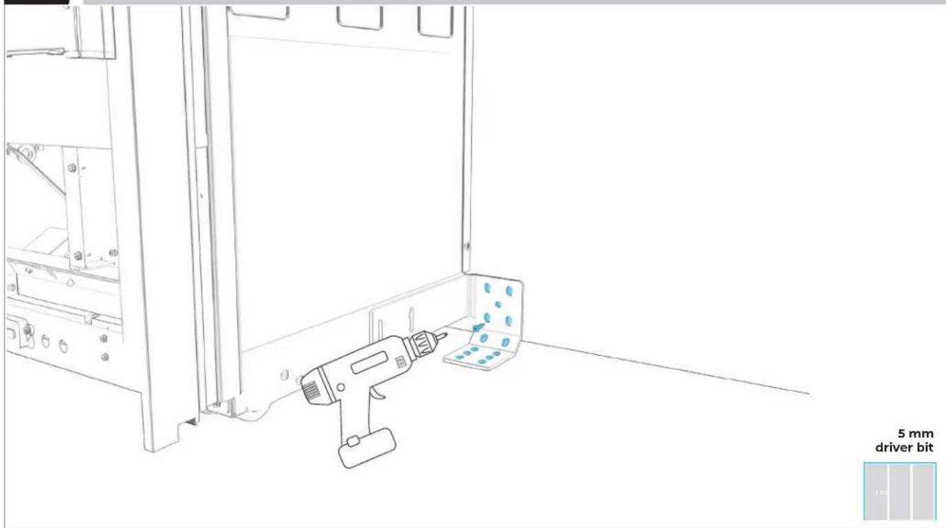
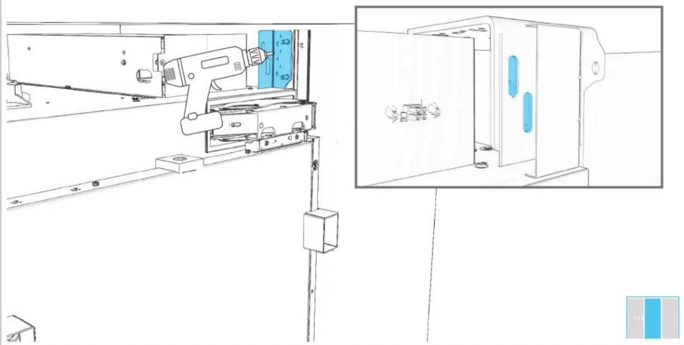
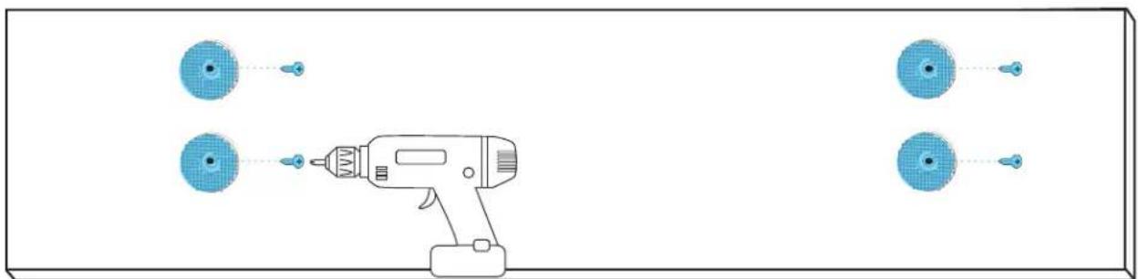
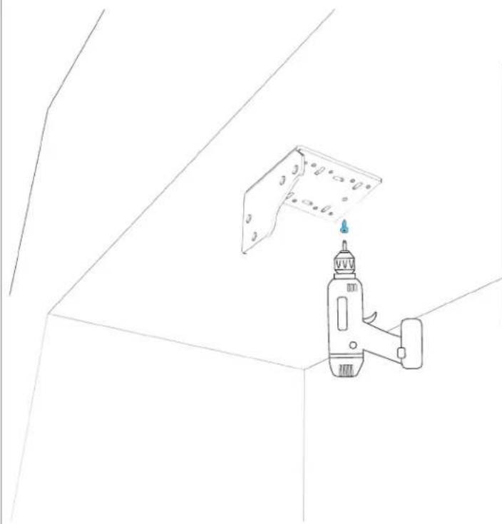
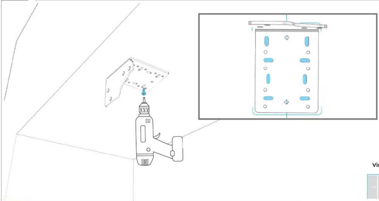
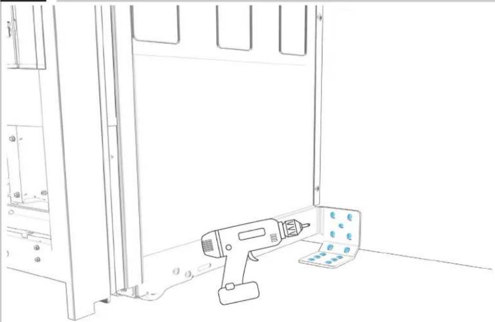
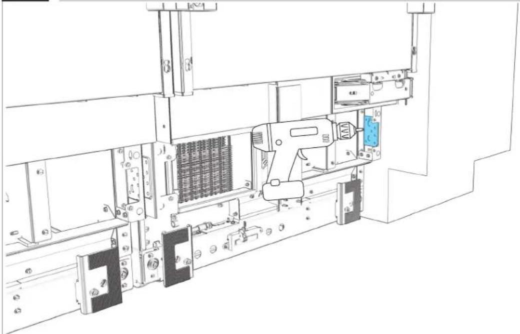
4.8
LOOSELY ATTACH BRACKET TO SOFFIT.
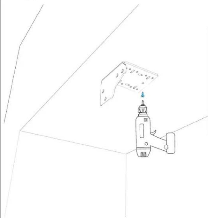
natural_image
Line drawing of a hand holding a power tool against a wall-mounted panel (no text or symbols)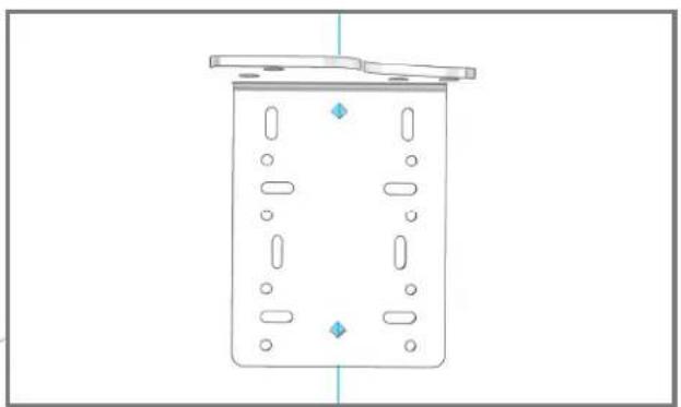
natural_image
Simple line drawing of a rectangular container with internal compartments and mounting flanges (no text or symbols)
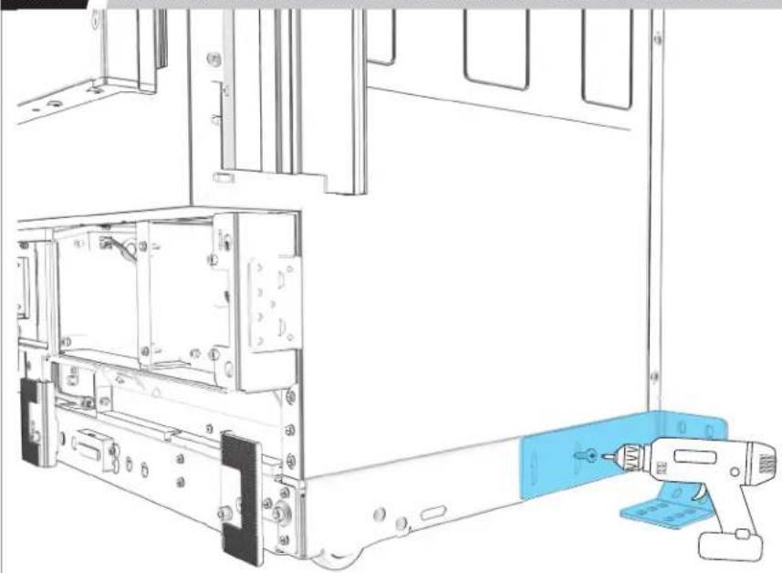
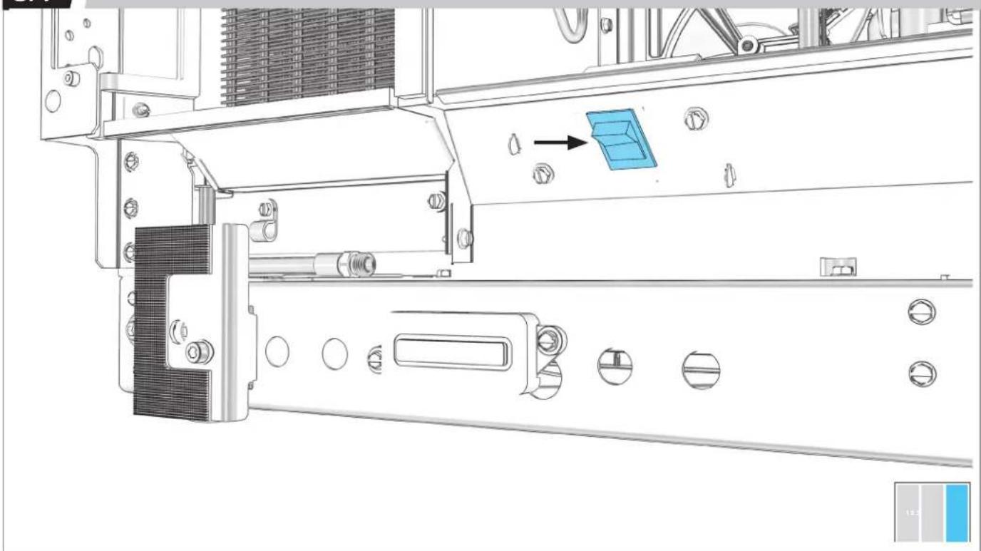
4.9
REALIGN BRACKET EDGES WITH ALIGNMENT LINES.
natural_image
Technical line drawing of a rectangular container with internal compartments and mounting points (no text or symbols)
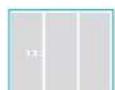
4.10
TIGHTEN 8 SCREWS.
natural_image
Technical line drawing of a mechanical device with a bracket and inset showing its internal components (no text or symbols)Wood screws


USE WOOD SCREWS OF AN APPROPRIATE LENGTH
4.11
SECURE BRACKET TO CABINET THROUGH ROUND HOLES.
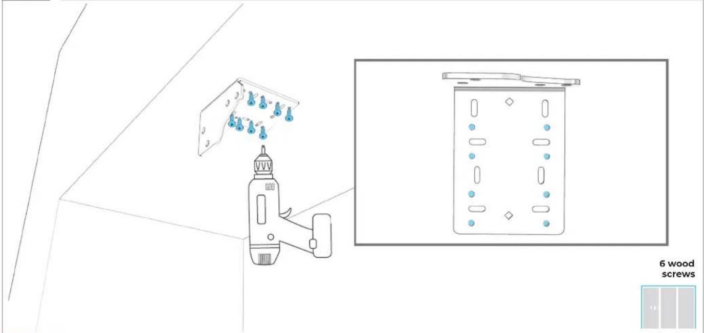
text_image
6 wood screws
A MINIMUM OF SIX SCREWS MUST BE USED TO SECURE BRACKETS TO CABINET. FAILING TO PROPERLY SECURE BRACKETS CAN RESULT IN A TIP HAZARD.
4.12
IF INSTALLING ONLY TWO COLUMNS:
GO TO SECTION 5
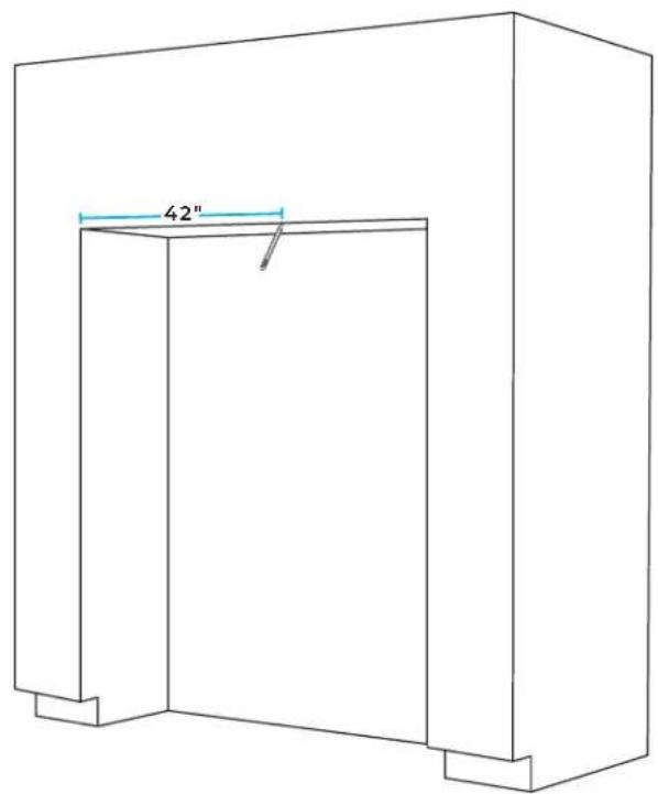
4.13
IF INSTALLING THREE COLUMNS: ADD TOGETHER MODEL WIDTHS OF FIRST AND SECOND COLUMNS.
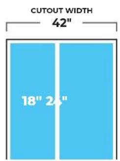
text_image
CUTOUT WIDTH 42" 18" 24"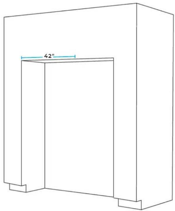
natural_image
Line drawing of a 3D rectangular structure with a labeled dimension of 42" (no text or symbols beyond the label)
4.14
MARK LINE AT CALCULATED WIDTH.
text_image
42"
4.15
COMPLETE 4.2-4.11.
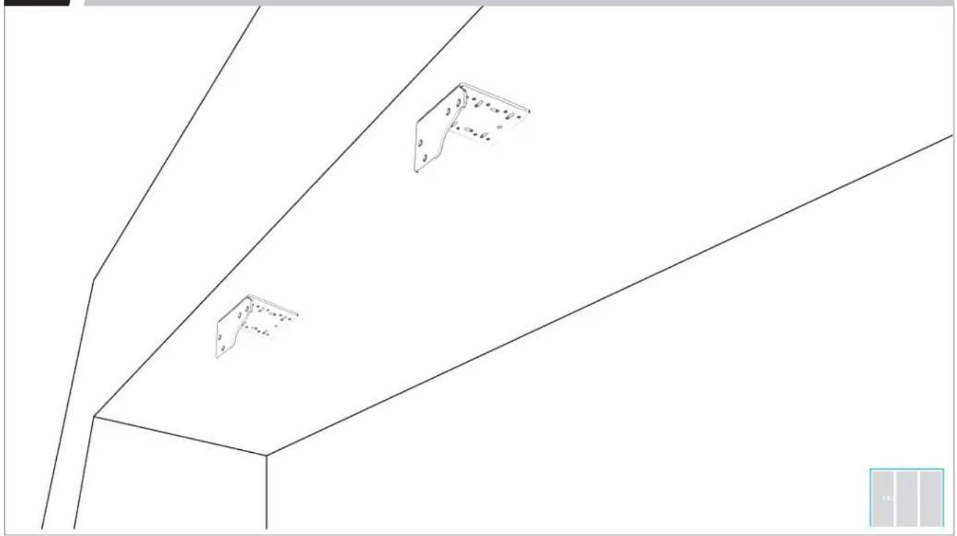
natural_image
Pure architectural line drawing of a building facade with three metal bracket symbols (no text or labels)PREPAR E
FURNITURE
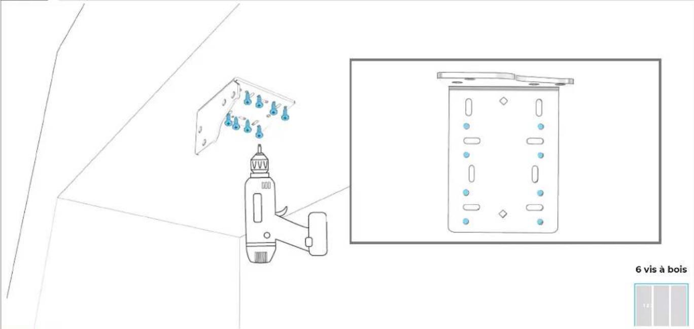
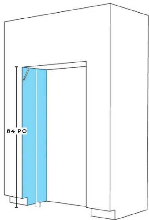
5.1
MEASURE AND MARK LEFT PANEL LINE.
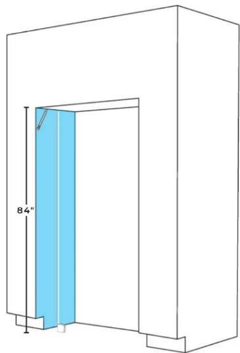
natural_image
Technical line drawing of a door frame with a blue panel and 84" height dimension label (no text or symbols beyond measurement)
5.2
POSITION TEMPLATE ON LEFT PANEL.
natural_image
Line drawing of a simple 3D rectangular structure with a blue label on the top right corner (no text or symbols on the structure itself)
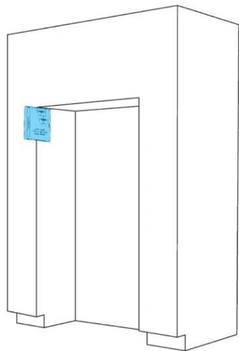
5.3
ALIGN DOOR STYLE LINE WITH CABINET FACE AND MARK ALIGNMENT LINES.

natural_image
Line drawing of a 3D rectangular structure with a small blue label on the top left corner (no text or symbols on the main diagram)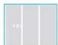
5.4
REPEAT 5.1-5.3 ON RIGHT PANEL.
natural_image
Line drawing of a simple 3D architectural structure with a door and corner brackets (no text or symbols)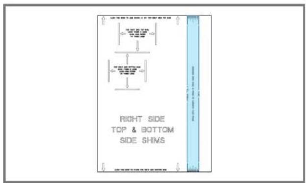
text_image
RIGHT SIDE TOP & BOTTOM SIDE SHIMS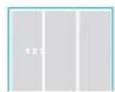
5.5
POSITION AND ALIGN TEMPLATE ON BOTTOM LEFT PANEL, MARKING SHIM ALIGNMENT LINES.
natural_image
Line drawing of a simple 3D rectangular structure with a small inset image showing a label 'A' (no text or symbols on the main diagram)
text_image
LEFT SIDE TOP & BOTTOM SIDE SHIMS
5.6
REPEAT STEP 5.5 ON RIGHT PANEL.
natural_image
Line drawing of a 3D rectangular structure with a vertical door and a small blue label on the right side (no text or symbols)
5.7
CRACK APART ROTTER SHIMS, ADHERE TO FOOTPRINTS.
natural_image
Line drawing of a simple 3D rectangular structure with a vertical door and corner supports (no text or symbols)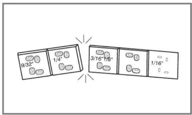
text_image
9/32" 1/4" 3/16"1/8" 1/16"
5.8
STACK ADDITIONAL SHIMS AS NEEDED.

natural_image
Line drawing of a 3D rectangular structure with a vertical door and corner supports (no text or symbols)
natural_image
Pure architectural floor plan lines without any text, numbers, or symbols
5.9
SECURE SHIMS TO SIDE PANELS (TWO SCREWS REQUIRED).
natural_image
Line drawing of a 3D rectangular enclosure with a door and wall, no text or symbols presentWood
screws

USE WOOD SCREWS OF AN APPROPRIATE LENGTH
5.10
TAPE WATER LINES TO FLOOR.
natural_image
Line drawing of a 3D rectangular structure with a double door and corner supports, showing no text or symbols.
FIRST
COLUMN INSTALLATION
6.1
SWITCH POWER OFF.

natural_image
Technical line drawing of a mechanical assembly with no visible text or symbolsBEFORE PLUGGING IN COLUMN, READ WARNING.
WARNING

Electrical Shock Hazard
Plug into a grounded 3 prong outlet.
Do not remove ground prong.
Do not use an adapter.
Do not use an extension cord.
Failure to follow these instructions can result in death, fire, or electrical shock.
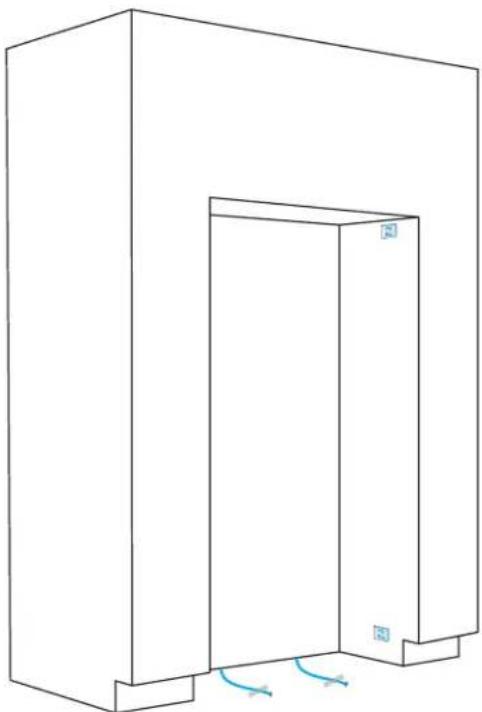
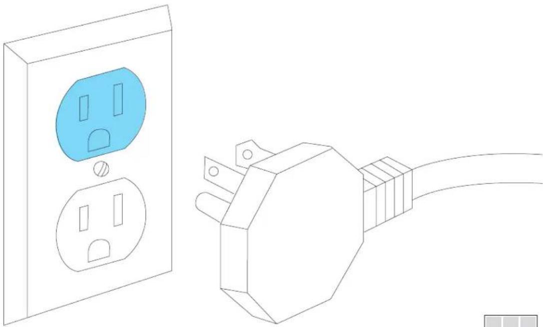
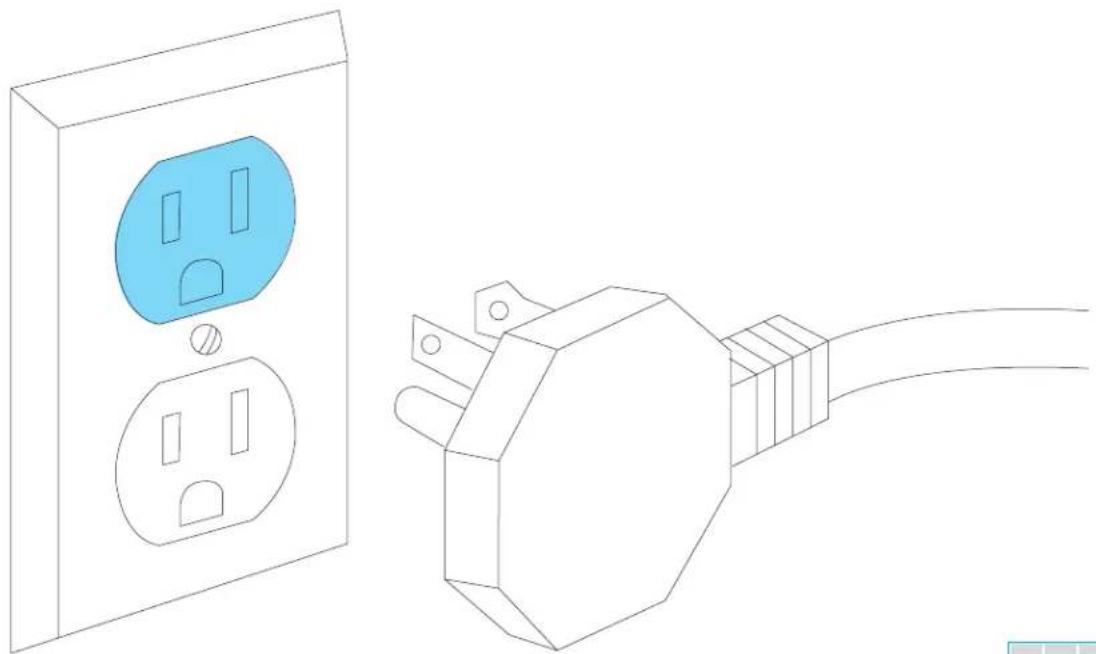
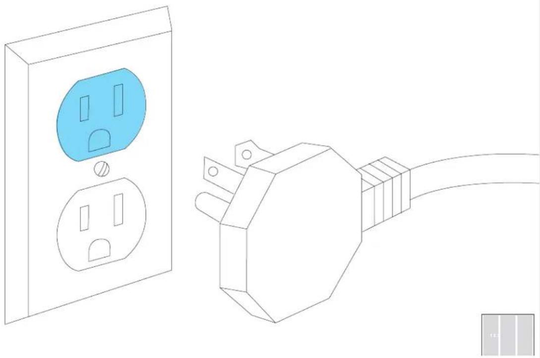
6.2
PLUG INTO GROUNDED 3-PRONG OUTLET.
natural_image
Line drawing of a wall socket connected to an electrical outlet plug (no text or symbols)BEFORE MOVING COLUMN, READ WARNING.
WARNING
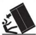
Tip Over Hazard
Refrigerator is top heavy and tips easily when not completely installed.
Keep doors taped closed until refrigerator is completely installed.
Use two or more people to move and install refrigerator.
Failure to do so can result in death or serious injury.
When Moving Your Refrigerator:
Your refrigerator is heavy. When moving the refrigerator for cleaning or service, be sure to cover the floor with cardboard or hardboard to avoid floor damage. Always pull the refrigerator straight out when moving it. Do not wiggle or "walk" the refrigerator when trying to move it, as floor damage could occur.
Important information to know about glass shelves and covers:
Do not clean glass shelves or covers with warm water when they are cold. Shelves and covers may break if exposed to sudden temperature changes or impact, such as bumping. Tempered glass is designed to shatter into many small, pebble-size pieces. This is normal. Glass shelves and covers are heavy. Use both hands when removing them to avoid dropping.
6.3
MOVE COLUMN INTO THE CUTOUT.
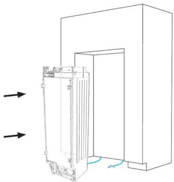
natural_image
Technical line drawing of a mechanical device with internal components and directional arrows indicating flow or movement (no text or symbols)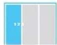

DO NOT DAMAGE THE WATER LINE.
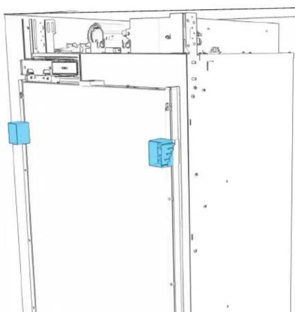
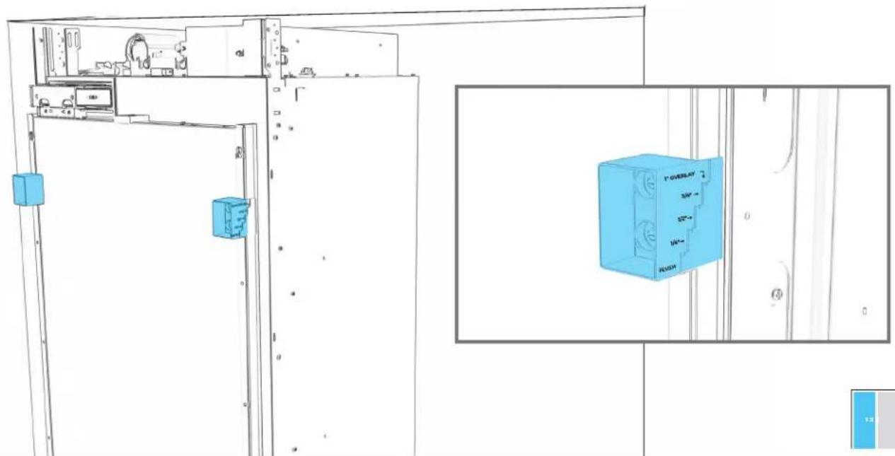
6.4
USE DEPTH GAUGES TO ALIGN (BASED ON DOOR STYLE).
natural_image
Technical line drawing of a cabinet or enclosure with two blue rectangular components, no visible text or symbols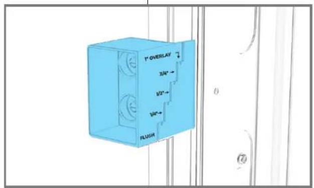
text_image
1" OVERLAY 3/4" 1/2" 1/8" FLUSH
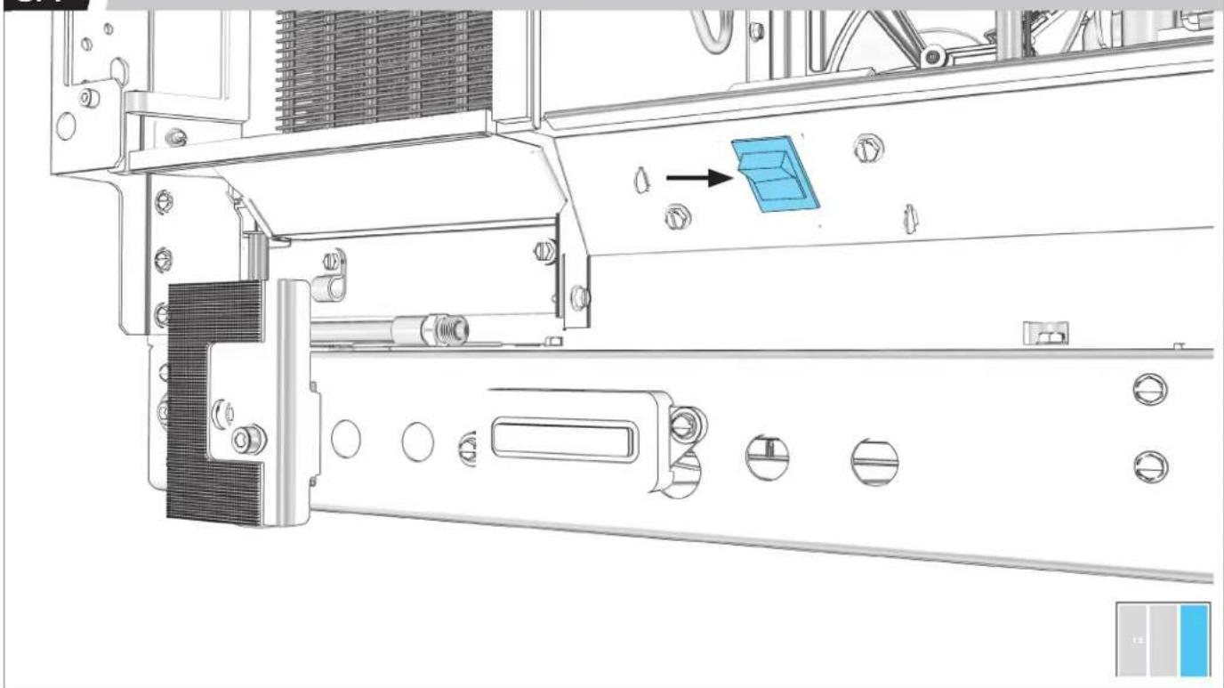
6.5
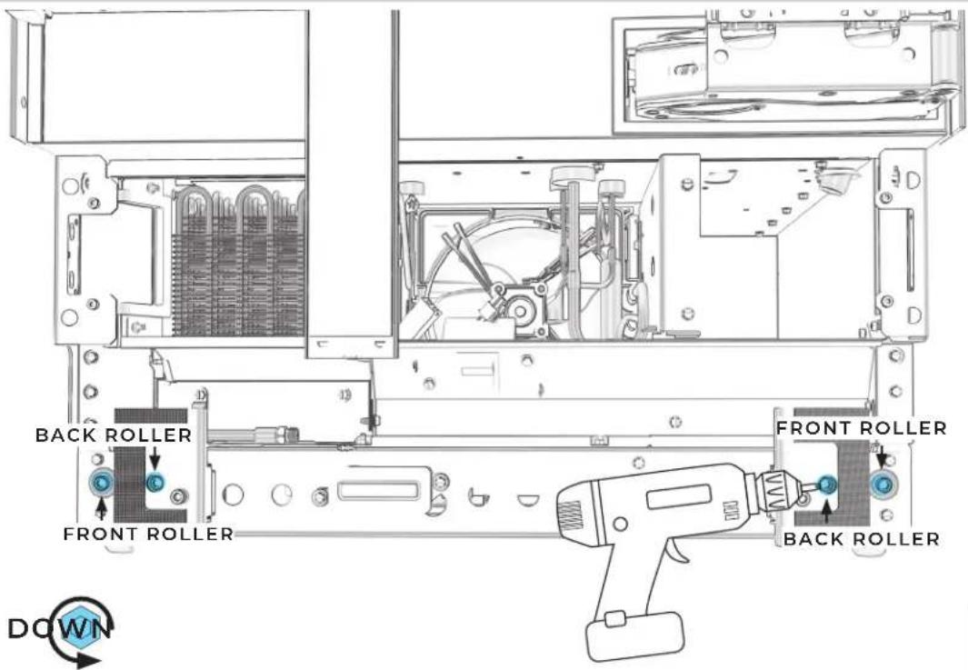
EXTEND ROLLERS INDIVIDUALLY.

natural_image
Technical line drawing of a server rack with internal components and ventilation ducts (no text or symbols)
6.7
CHECK THAT DEPTH GAUGES INDICATE SAME DEPTH.
text_image
Technical diagram showing front and side views of an appliance with labeled components and a 3D preview of the 'F' overlay.
6.8
ADJUST ROLLERS UNTIL DEPTH GAUGES MATCH.
text_image
#2 square drive 1.2.56.10
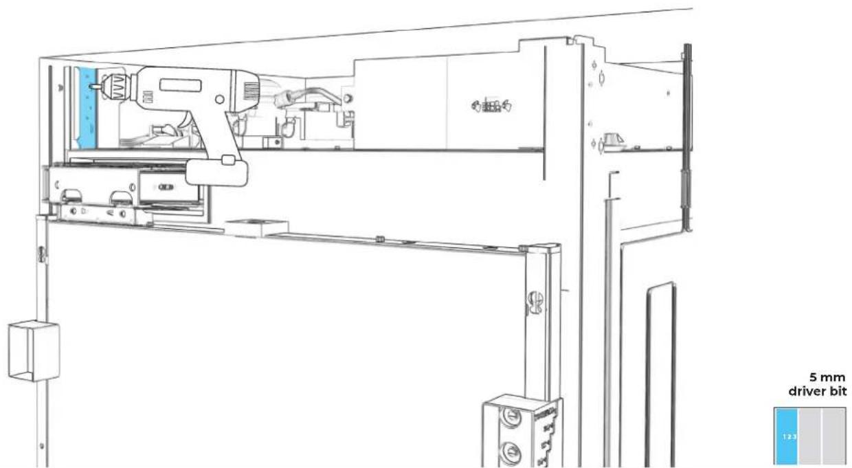
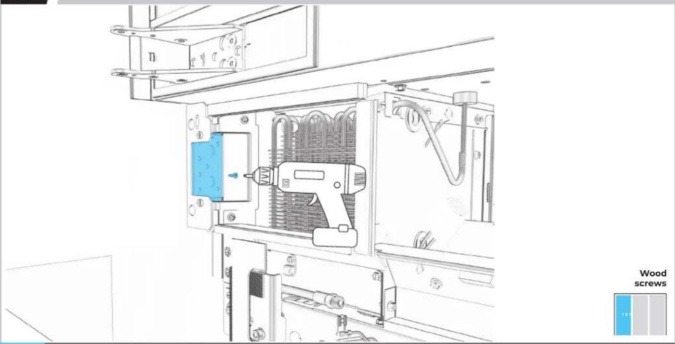
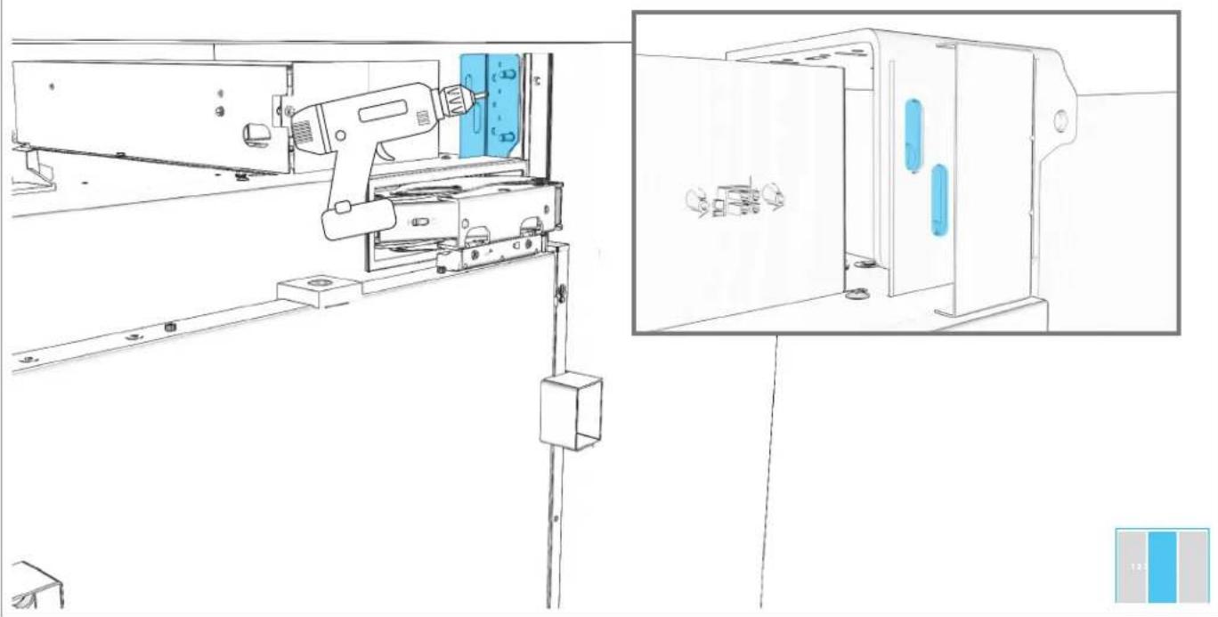
SECURE TOP INSTALLATION BRACKET TO FURNITURE.
text_image
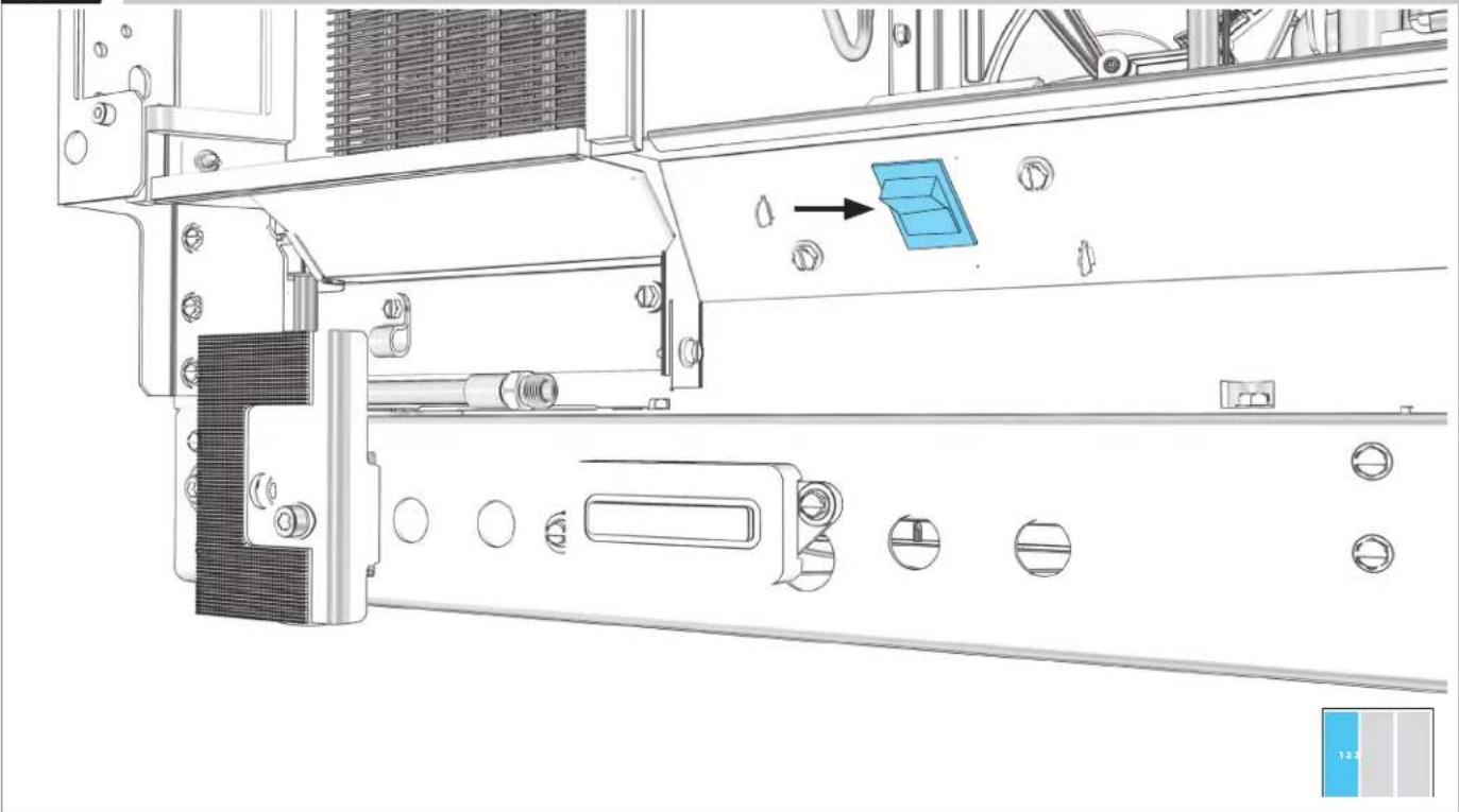
5 mm driver bit6.11
SECURE BOTTOM INSTALLATION BRACKET TO FURNITURE.
natural_image
Technical line drawing of an electrical enclosure with a tool inside, showing internal components and mounting brackets (no text or symbols)
USE WOOD SCREWS OF AN APPROPRIATE LENGTH.
6.12
POSITION BRACKET TO FLOOR AND WALL.
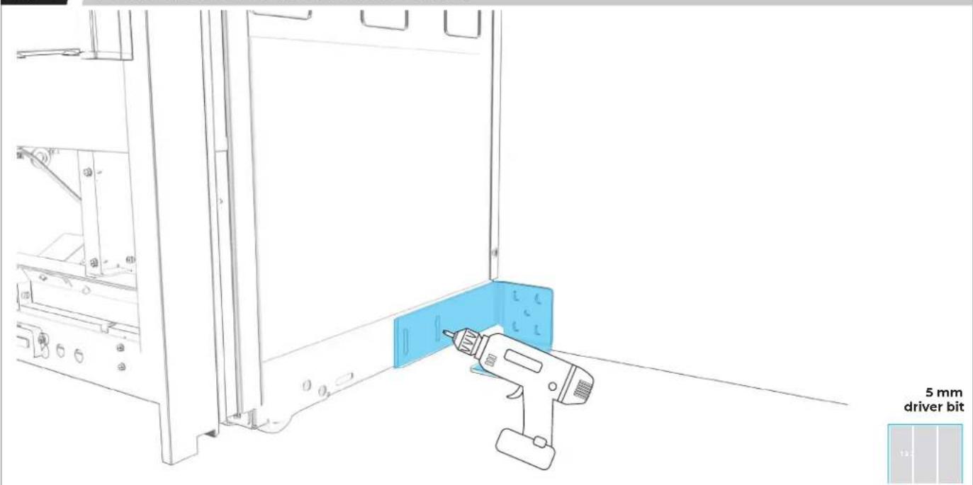
text_image
5 mm driver bit
CONSIDER WALL AND FLOOR CONSTRUCTION AND MATERIALS.
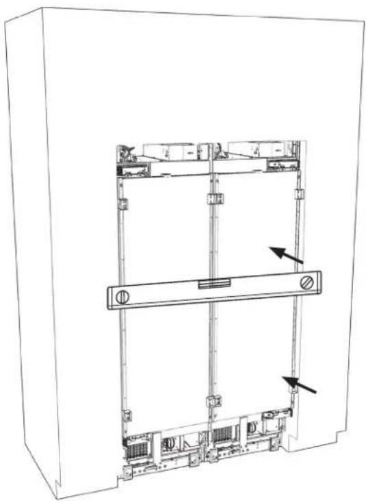
6.13
SECURE POSITIONING BRACKET, USING AS MANY SLOTS AS POSSIBLE.
natural_image
Line drawing of a mechanical device with a 5 mm driver bit indicator (no text or symbols on the diagram itself)6.14
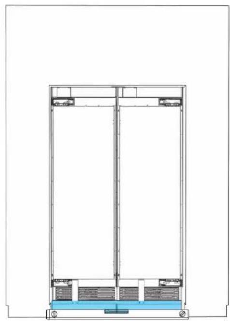
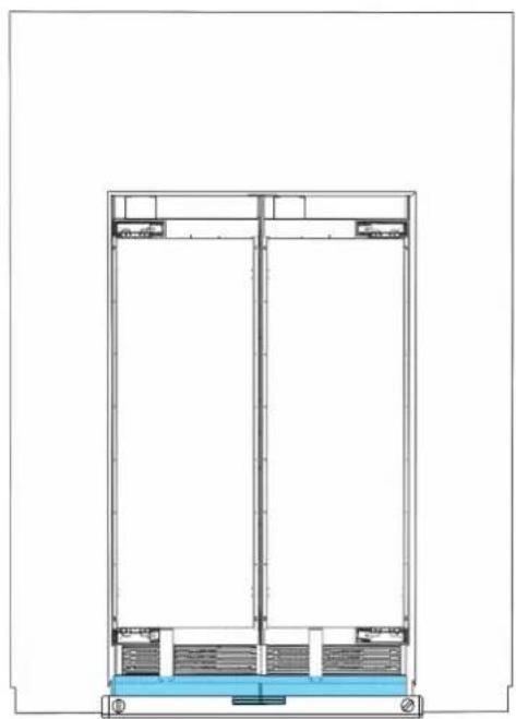
USE LEVEL TO CHECK DEPTH FROM FACE FRAME AT MULTIPLE POINTS.

text_image
FURNITURE COLUMN 1 DEPTH GAUGE MAY SUBSTITUTE TRIM PIECE FOR LEVEL.6.15
READJUST COLUMN SO THAT ALL DEPTHS MATCH.
natural_image
Technical line drawing of a mechanical assembly with mounting holes and a horizontal bar (no text or symbols)
SECOND
COLUMN INSTALLATION
7.1
SWITCH POWER OFF.

natural_image
Technical line drawing of a mechanical assembly with no visible text or symbolsBEFORE PLUGGING IN COLUMN, READ WARNING.
WARNING

Electrical Shock Hazard
Plug into a grounded 3 prong outlet.
Do not remove ground prong.
Do not use an adapter.
Do not use an extension cord.
Failure to follow these instructions can result in death, fire, or electrical shock.
7.2
PLUG INTO GROUNDED 3-PRONG OUTLET.
natural_image
Line drawing of a wall socket connected to an electrical outlet plug (no text or symbols)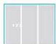
BEFORE MOVING COLUMNS, REVIEW ALL WARNINGS.
WARNING
Tip Over Hazard
Refrigerator is top heavy and tips easily when not completely installed.
Keep doors taped closed until refrigerator is completely installed.
Use two or more people to move and install refrigerator.
Failure to do so can result in death or serious injury.
When Moving Your Refrigerator:
Your refrigerator is heavy. When moving the refrigerator for cleaning or service, be sure to cover the floor with cardboard or hardboard to avoid floor damage. Always pull the refrigerator straight out when moving it. Do not wiggle or "walk" the refrigerator when trying to move it, as floor damage could occur.
Important information to know about glass shelves and covers:
Do not clean glass shelves or covers with warm water when they are cold. Shelves and covers may break if exposed to sudden temperature changes or impact, such as bumping. Tempered glass is designed to shatter into many small, pebble-size pieces. This is normal. Glass shelves and covers are heavy. Use both hands when removing them to avoid dropping.
7.3
SECOND COLUMN: MOVE INTO THE CUTOUT.
natural_image
Technical line drawing of an electrical enclosure with internal components and mounting holes (no text or symbols)
7.4
IF INSTALLING THREE COLUMNS:
GO TO SECTION 8
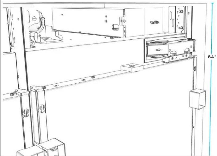
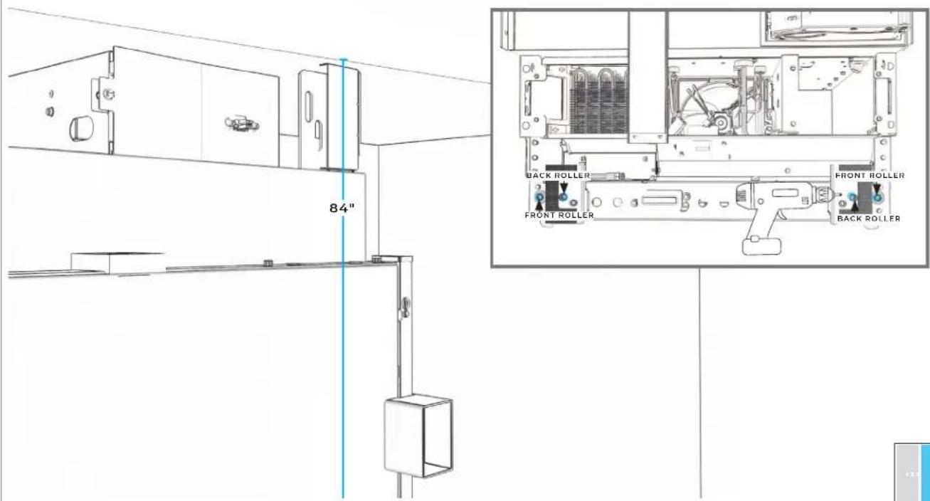
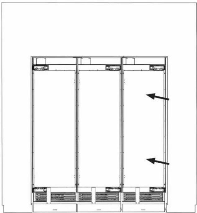
7.5
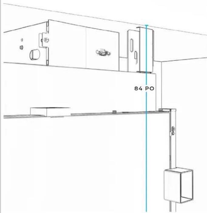
SECOND COLUMN: RAISE TO 84" LINE.
natural_image
Technical line drawing of a mechanical assembly with mounting brackets and a door (no text or symbols)
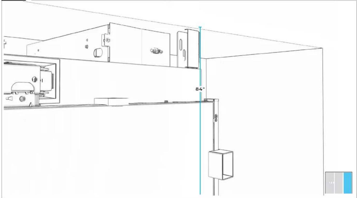
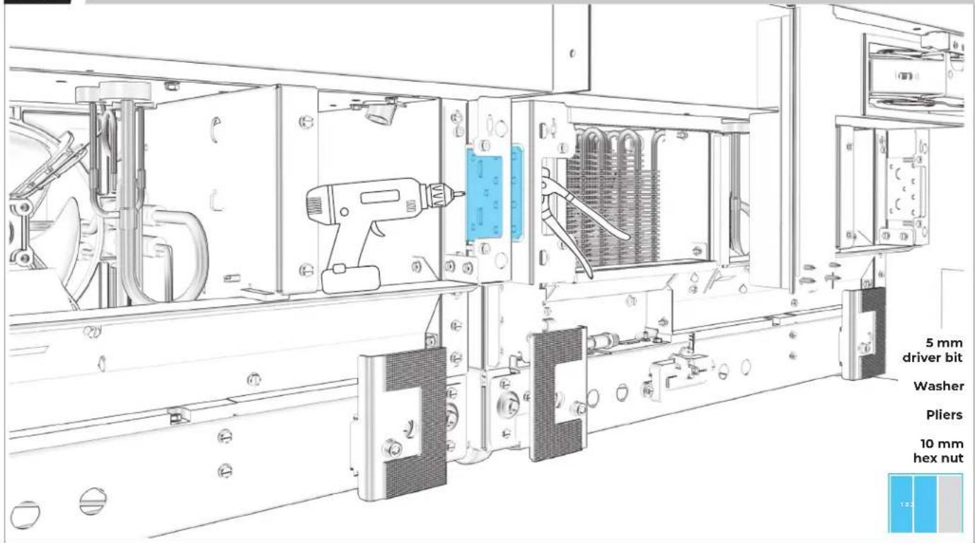
7.6
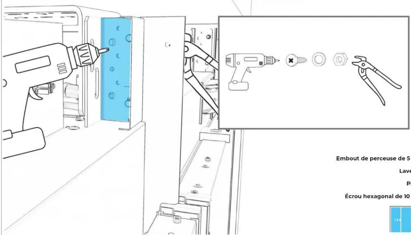
SECURE FIRST UNIT TO SECOND UNIT AT TOP.
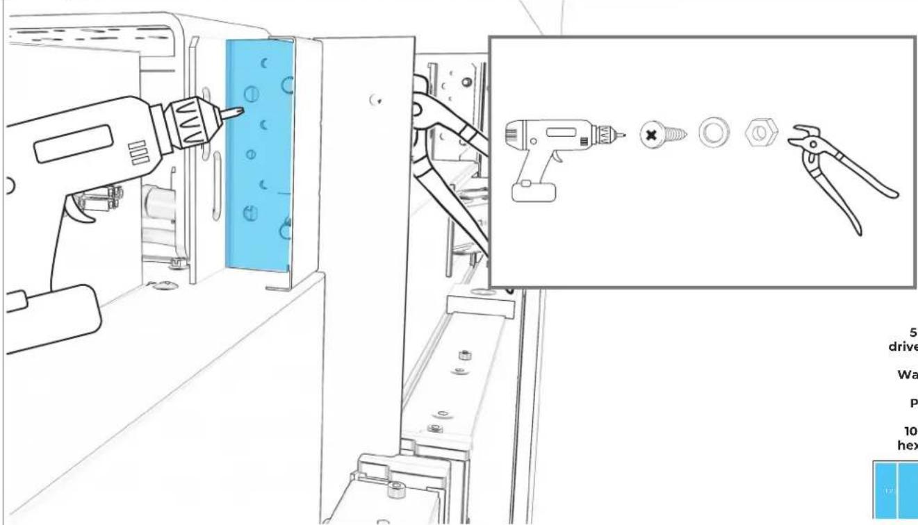
text_image
Technical diagram showing a tool in a machine with a close-up of a drill bit and pliers, accompanied by a technical description panel.5 mm
driver bit
Washer
Pliers
10 mm hex nut
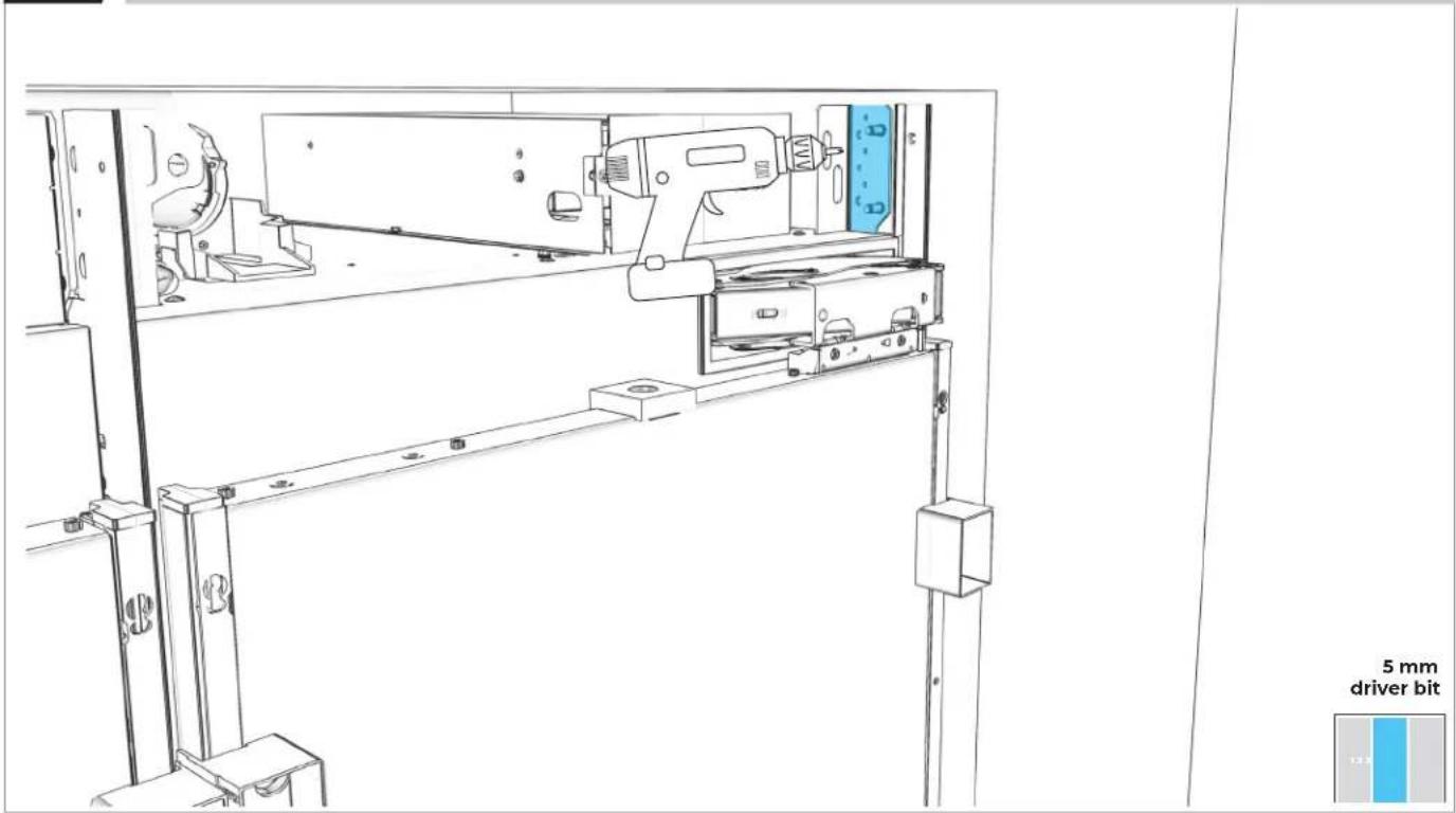
7.7
REPEAT ON BOTTOM BRACKET.

text_image
5 mm driver bit Washer Pliers 10 mm hex nut7.8
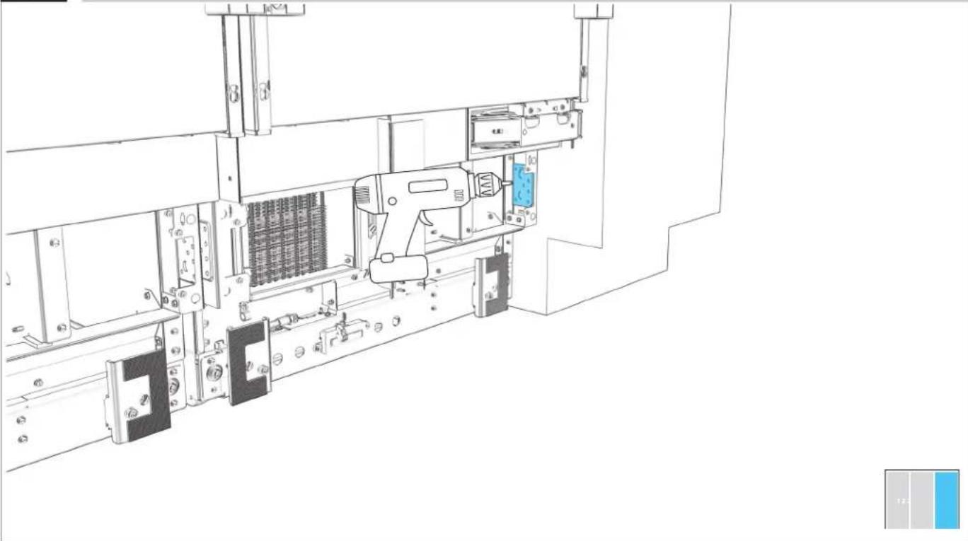
SECURE TOP INSTALLATION BRACKET TO FURNITURE.
text_image
5 mm driver bit7.9
SECURE BOTTOM INSTALLATION BRACKET TO FURNITURE.
natural_image
Technical line drawing of a mechanical assembly with a drill pen and blue component, no visible text or symbols
USE WOOD SCREWS OF AN APPROPRIATE LENGTH
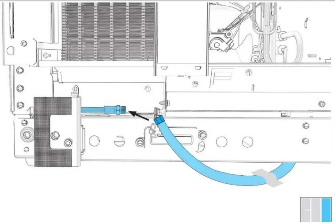
7.10
CONNECT THE WATER SUPPLY LINES.
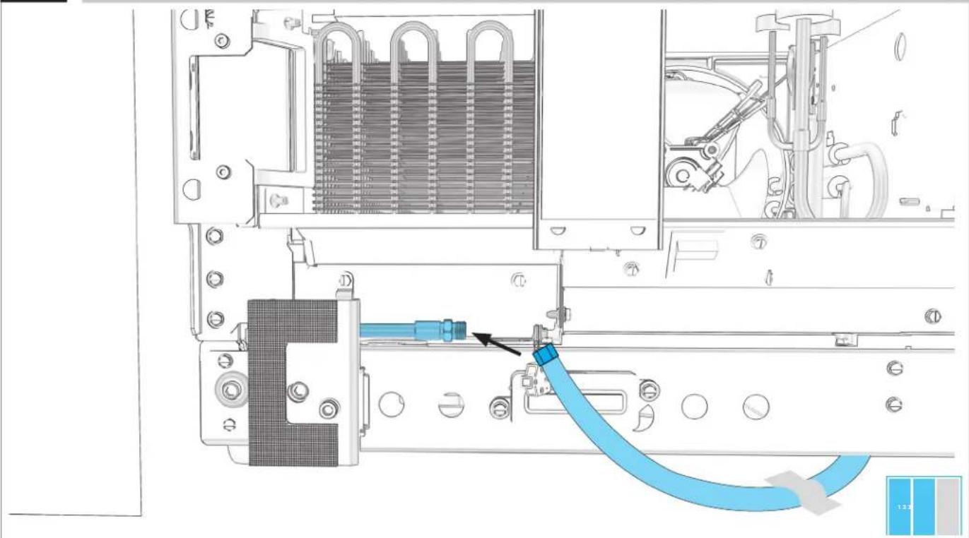
natural_image
Technical diagram of an internal mechanical assembly with a blue cable being inserted into a component (no text or symbols visible)7.11
IF INSTALLING ONLY TWO COLUMNS:
GO TO SECTION 9
THIRD
COLUMN INSTALLATION
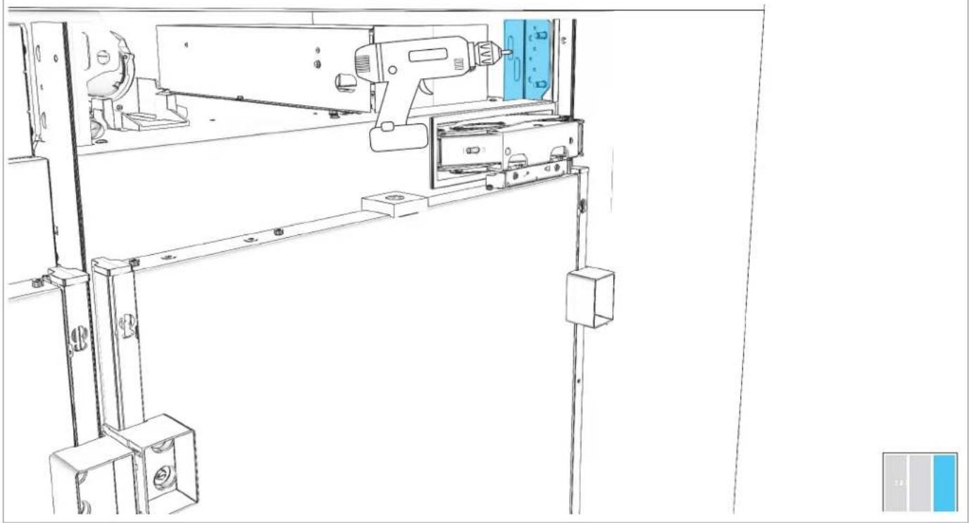
8.1
SECOND COLUMN: RAISE TO 84" LINE.
natural_image
Line drawing of a mechanical device with a drill bit and control panel, no text or symbols present
8.3
LOOSELY DRIVE SCREWS THROUGH INSTALLATION BRACKET AND BADASS SOFFIT BRACKET.
natural_image
Technical line drawing of a mechanical assembly with a tool and component, shown from two different angles (no text or symbols present)8.4
THIRD COLUMN: SWITCH OFF POWER.
natural_image
Technical line drawing of a mechanical assembly with no visible text or symbolsBEFORE PLUGGING IN COLUMN, READ WARNING.
WARNING
Electrical Shock Hazard
Plug into a grounded 3 prong outlet.
Do not remove ground prong.
Do not use an adapter.
Do not use an extension cord.
Failure to follow these instructions can result in death, fire, or electrical shock.
8.5
PLUG INTO GROUNDED 3-PRONG OUTLET.
natural_image
Line drawing of an electrical outlet and a connected power plug (no text or symbols)BEFORE MOVING COLUMN, READ ALL WARNINGS.
WARNING
Tip Over Hazard
Refrigerator is top heavy and tips easily when not completely installed.
Keep doors taped closed until refrigerator is completely installed.
Use two or more people to move and install refrigerator.
Failure to do so can result in death or serious injury.
When Moving Your Refrigerator:
Your refrigerator is heavy. When moving the refrigerator for cleaning or service, be sure to cover the floor with cardboard or hardboard to avoid floor damage. Always pull the refrigerator straight out when moving it. Do not wiggle or "walk" the refrigerator when trying to move it, as floor damage could occur.
Important information to know about glass shelves and covers:
Do not clean glass shelves or covers with warm water when they are cold. Shelves and covers may break if exposed to sudden temperature changes or impact, such as bumping. Tempered glass is designed to shatter into many small, pebble-size pieces. This is normal. Glass shelves and covers are heavy. Use both hands when removing them to avoid dropping.
8.7
THIRD COLUMN: MOVE INTO THE CUTOUT.
natural_image
Architectural floor plan showing three rectangular sections with windows and doorways, no text or symbols present
8.8
THIRD COLUMN: RAISE TO 84" LINE.
natural_image
Technical line drawing of a cabinet or enclosure assembly with a 84-inch vertical dimension marker (no text or symbols present)8.9
SECURE SECOND UNIT TO THIRD UNIT AT TOP.
text_image
5 mm driver bit Washer Pliers 10 mm hex nut 12.38.10
REPEAT ON BOTTOM BRACKET.
text_image
5 mm driver bit Washer Pliers 10 mm hex nut8.11
THIRD COLUMN: SECURE TO RIGHT SIDE PANEL.
natural_image
Technical line drawing of a mechanical assembly with no visible text or symbols8.12
THIRD COLUMN: REPEAT ON BOTTOM BRACKET.
natural_image
Technical line drawing of a mechanical assembly with no visible text or symbols8.13
CONNECT THE WATER SUPPLY LINE.
natural_image
Technical diagram of a mechanical assembly with blue hoses and a component, no visible text or symbolsPREPAR E
COLUMNS FOR USE
9.1
EACH COLUMN: ALIGN FILTER HOUSING BETWEEN BRACKETS ON TOP OF COLUMN.

natural_image
Technical line drawing of a mechanical assembly with blue component placement (no text or symbols)9.2
EACH COLUMN: REINSTALL HOUSING, PUSHING LEFT WITH FORCE.

natural_image
Technical line drawing of a mechanical assembly with blue component and mounting holes (no text or symbols)9.3
EACH COLUMN: INSERT WATER FILTER UNTIL SEATED.

natural_image
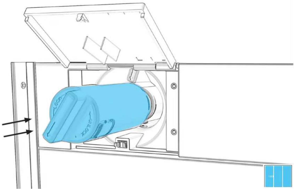
Technical line drawing of a mechanical device with blue component and directional arrows (no text or symbols)9.4
EACH COLUMN: ROTATE FILTER CLOCKWISE TO ALIGN ARROWS.
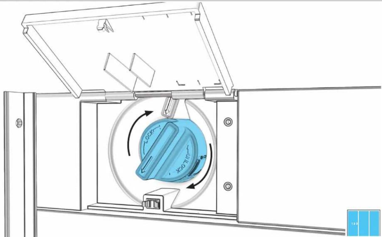
text_image
Technical diagram of a mechanical device with labeled components and directional arrows indicating motion or movement.9.5
EACH COLUMN: SECURE WITH TWO SCREWS AND REPLACE TOP COVER.
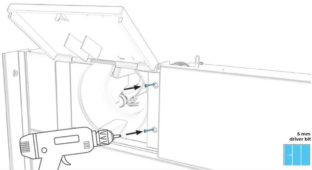
text_image
5 mm driver bit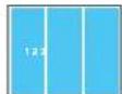
9.6
EACH COLUMN: REINSTALL AIR GRILLE.
text_image
Technical diagram of a server rack with blue internal compartments and labeled components in Chinese
9.7
EACH COLUMN: TURN POWER ON

natural_image
Technical line drawing of a mechanical assembly with no visible text or symbols
INSTALLATION CHECKPOINT
PG.86 CUSTOM WOOD TOE-KICK PREPARATION
PG.89 STAINLESS STEEL TOE-KICK PREPARATION
PG.92 ALIGN AND INSTALL ALL TOE-KICKS
TOE-KICK
CUSTOM WOOD PREPARATION
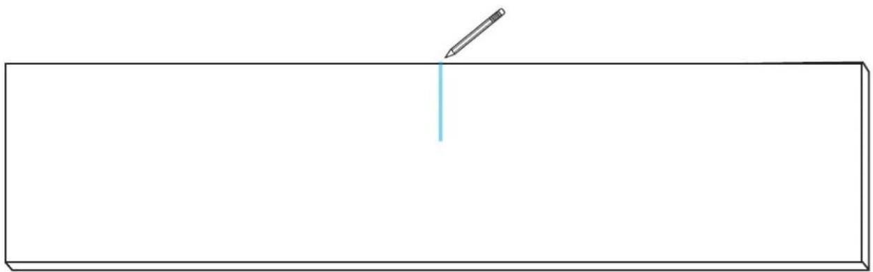
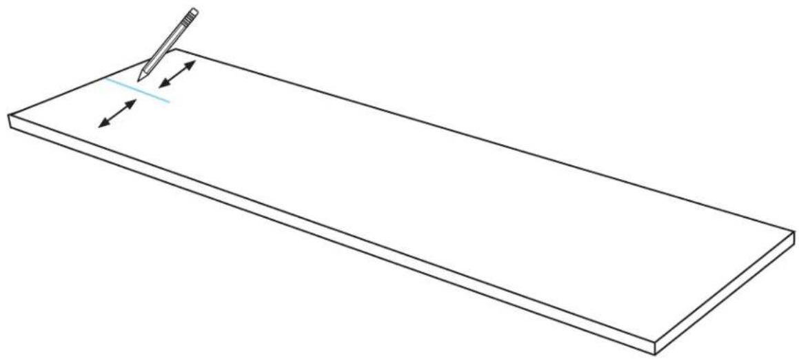
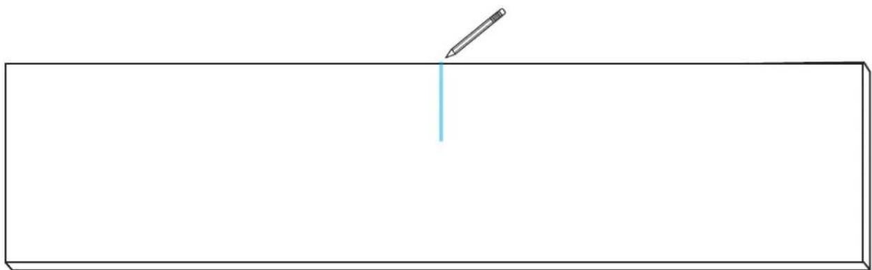
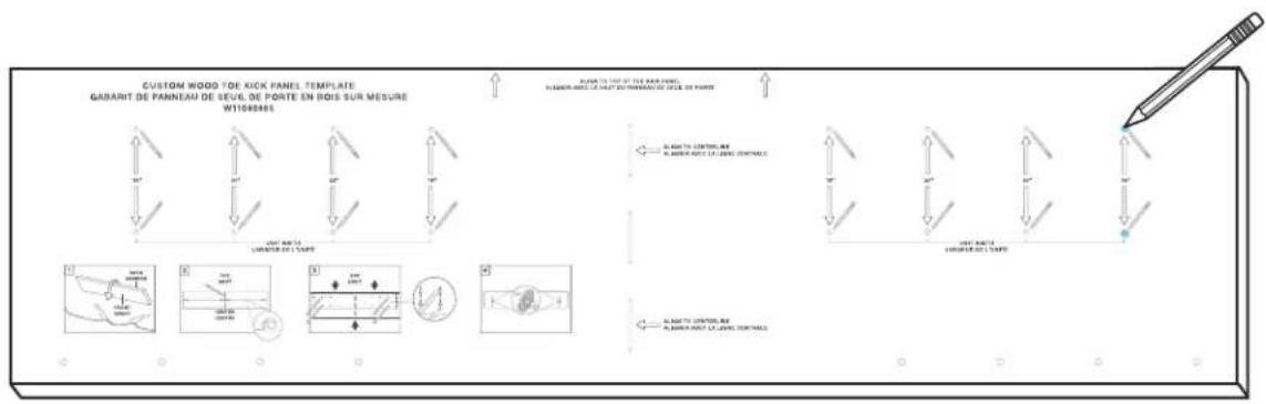
10.1
MEASURE AND MARK CENTERLINE OF TOE-KICK.
natural_image
Simple line drawing of a pencil writing on a blank rectangular surface (no text or symbols)

COMPLETE ALL STEPS FOR EACH UNIT.
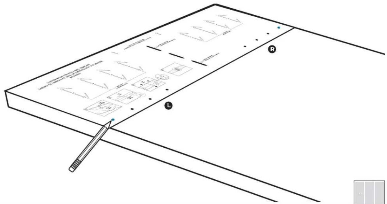
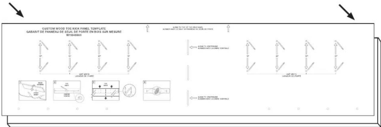
10.2
ALIGN TEMPLATE
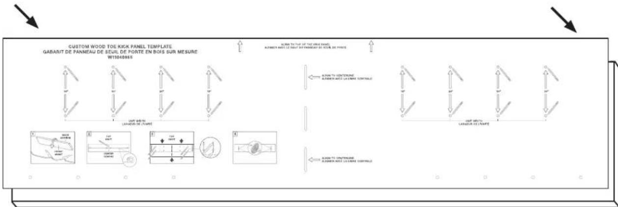
text_image
CUSTOM WOOD TOE KICK PANEL TEMPLATE GABARIT DE PANNEAU DE SEUIL DE PORTE EN BOIS SUR MESURE W13040865 ALUM TO TUIF OF THE CANDI BARET ALUMIN PARLE LE DINIT BY PANNEAU DE NOUE DE POATE ALUM TO CONTENUE ALUMIN PARLE LA CHINE CONTINUE ALUM TO CONTENUE ALUMIN PARLE LA CHINE CONTINUE
10.3
MARK GRIPPING PAD LOCATIONS.
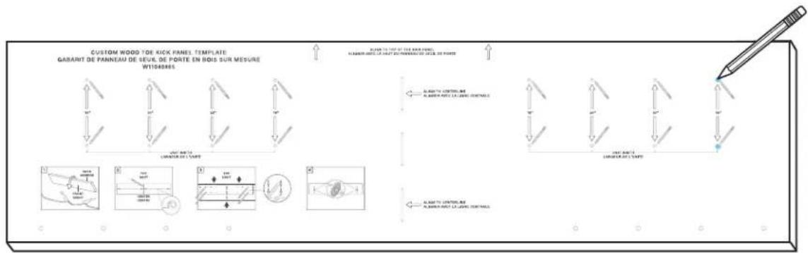
text_image
CUSTOM WOOD TOE KICK PANEL TEMPLATE GABARIT DE PANNEAU DE SEVAL DE PORTE EN BOIS SUR MESURE W1083865 RABARIT TO THE 200 WOOD PANELS ALABARI PAROT LE VARE ET DU PRAVAN DU FLEX DE POWER ALABARI PAROT LE VARE ET DU PRAVAN DU FLEX DE POWER ALABARI PAROT LE VARE ET DU PRAVAN DU FLEX DE POWER ALABARI PAROT LE VARE ET DU PRAVAN DU FLEX DE POWER ALABARI PAROT LE VARE ET DU PRAVAN DU FLEX DE POWER ALABARI PAROT LE VARE ET DU PRAVAN DU FLEX DE FORCE ALABARI PAROT LE VARE ET DU PRAVAN DU FLEX DE FORCE
10.5
ADHERE GRIPPING PADS TO POINTS.
natural_image
Diagram of a handheld electric drill with four circular components and two dashed lines indicating positions (no text or symbols)
TOE-KICK
STAINLESS STEEL PREPARATION
11.1
EACH COLUMN: UNSCREW AND DISCARD WIFI HARNESS.

natural_image
Technical diagram of a mechanical assembly with blue plastic component and directional arrows indicating movement (no text or symbols)
11.2
DISCONNECT BLUE WIFI WIRE FROM HARNESS.

natural_image
Technical line drawing of a mechanical assembly with circular components and a blue connector (no text or symbols)
11.3
ATTACH BLUE TOE-KICK AND COLUMN WIRES.

natural_image
Technical line drawing of a device panel with an inset showing two connected components (no text or symbols)
TOE-KICK
ALIGN AND INSTALL
12.1
ALIGN TOE-KICK BRACKETS WITH FURNITURE TOE-KICK.
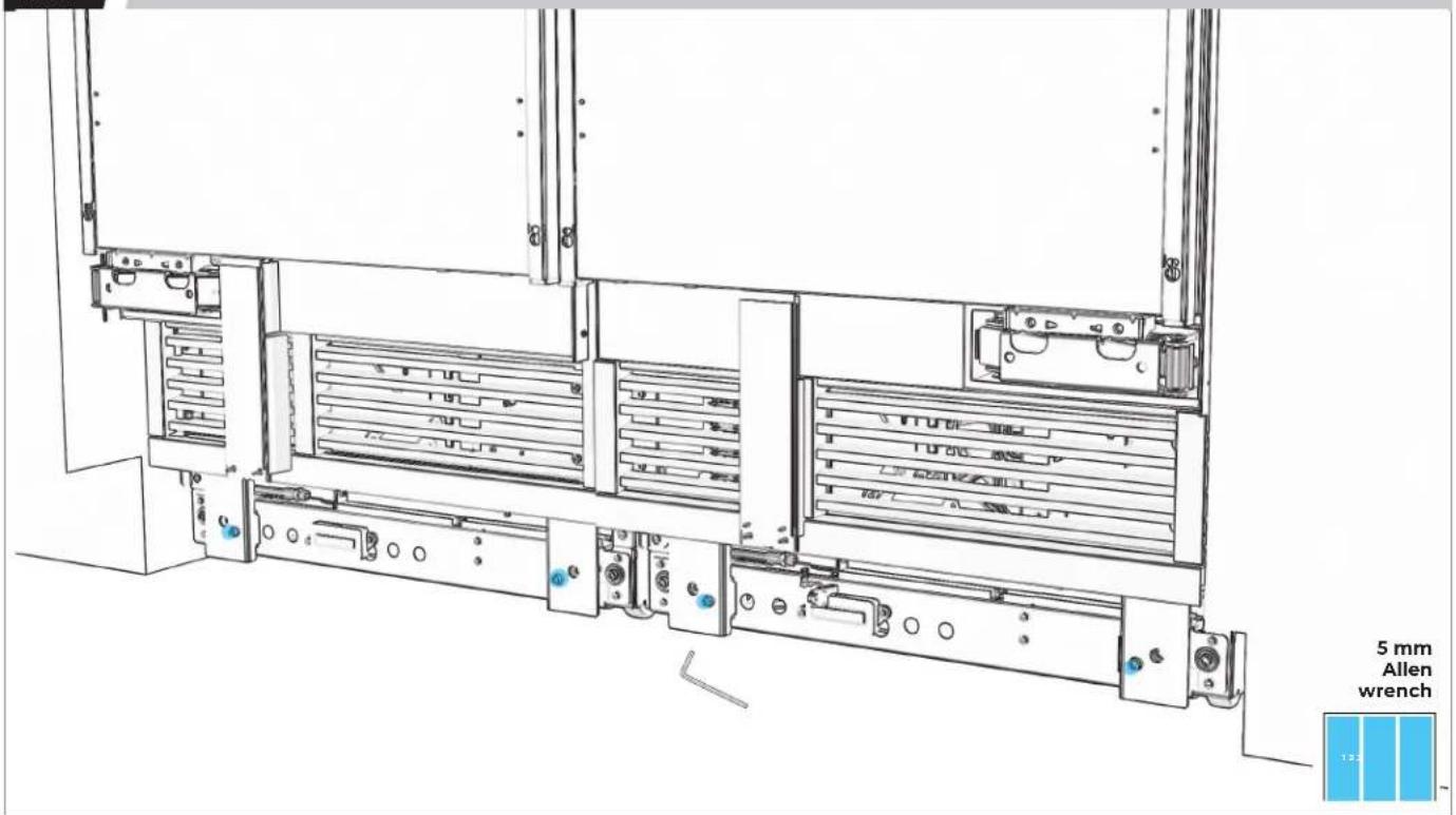
text_image
5 mm Allen wrench 13212.2
CHECK THAT BRACKETS ARE IN PLANE.
natural_image
Technical line drawing of a server rack with multiple drive bays and ventilation slots (no text or symbols)12.3
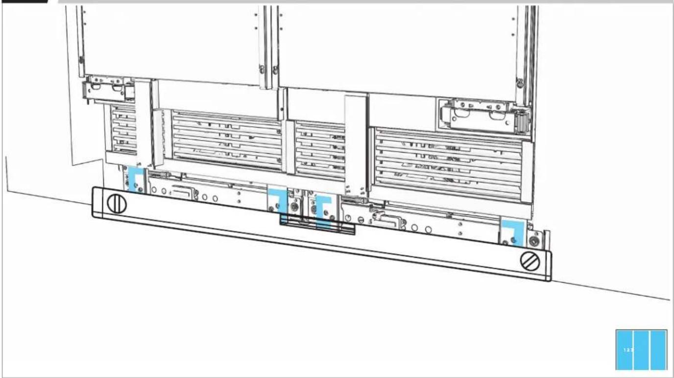
ALIGN TOE-KICK GRIPPING PADS WITH BRACKETS.
natural_image
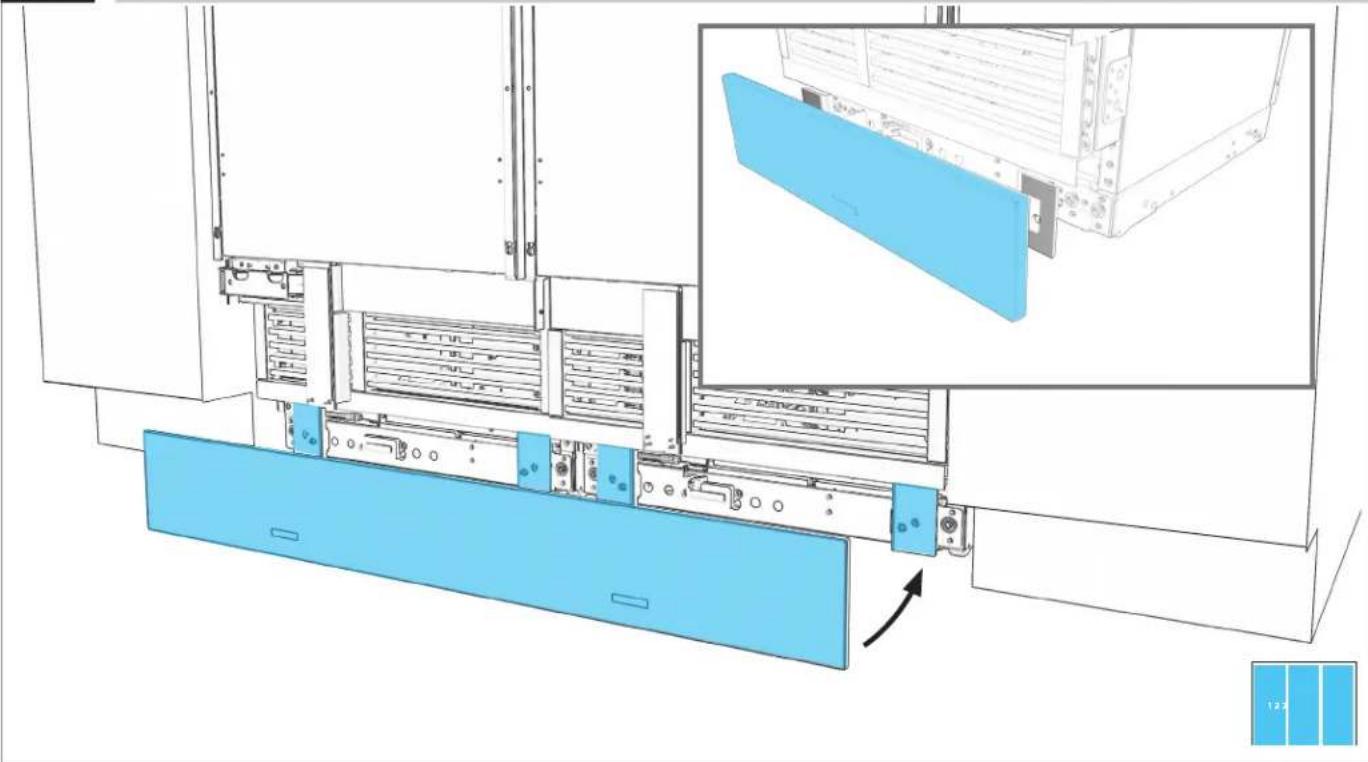
Technical diagram of a server rack with blue panel and inset view showing internal components (no text or symbols)12.4
PRESS FIRMLY TO ATTACH.
text_image
Technical diagram of a server rack system with labeled components and a blue panel inset showing internal structure.12.5
MEASURE OFFSET. IF UNEVEN, REMOVE TOE-KICK.
natural_image
Architectural cross-section diagram of a multi-level building or structure with structural elements (no text or labels)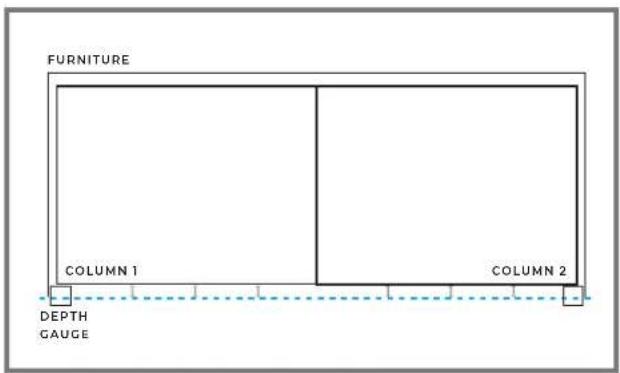
text_image
FURNITURE COLUMN 1 COLUMN 2 DEPTH GAUGE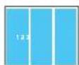
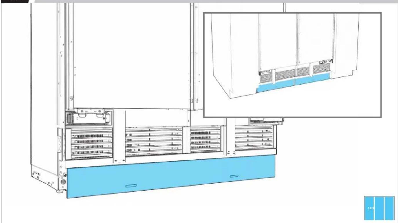
12.6
ADJUST BRACKETS TO ALIGN TOE-KICK.

text_image
5 mm Allen wrench12.7
CONFIRM ALIGNMENT, READJUSTING IF NECESSARY.
natural_image
Architectural cross-section diagram of a multi-story building facade with structural elements (no text or labels)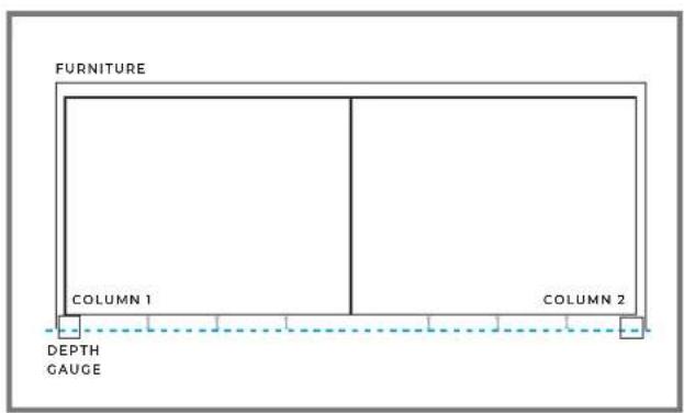
text_image
FURNITURE COLUMN 1 COLUMN 2 DEPTH GAUGE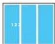
P ∧ N E I.
CUSTOM WOOD PREPARATION
13.1
natural_image
Line drawing of a refrigerator interior showing front and side views (no text or symbols)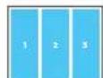

COMPLETE ALL STEPS FOR EACH UNIT.
13.2
PLACE PANEL FACE-DOWN.
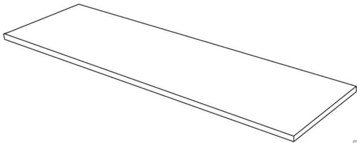
natural_image
Simple line drawing of a rectangular plate or shelf (no text or symbols)

PLACE ON A FLAT, COVERED SURFACE.
13.3
MEASURE AND MARK CENTER OF PANEL.
natural_image
Line drawing of a rectangular plate with a pencil and directional arrows indicating writing or editing (no text or symbols)
13.4
MARK LEFT AND RIGHT HOLES.
text_image
Technical diagram of a mechanical assembly with labeled components and annotations13.5
DRILL HOLES.
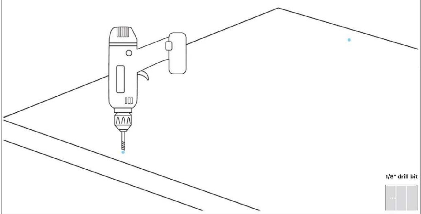
text_image
1/8" drill bit13.6
DRIVE FASTENERS INTO PRE-DRILLED LOCATIONS.
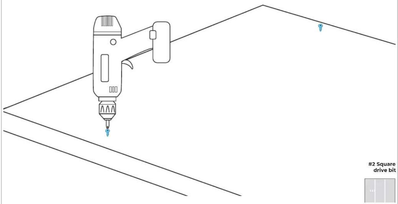
text_image
#2 Square drive bit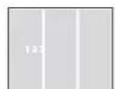
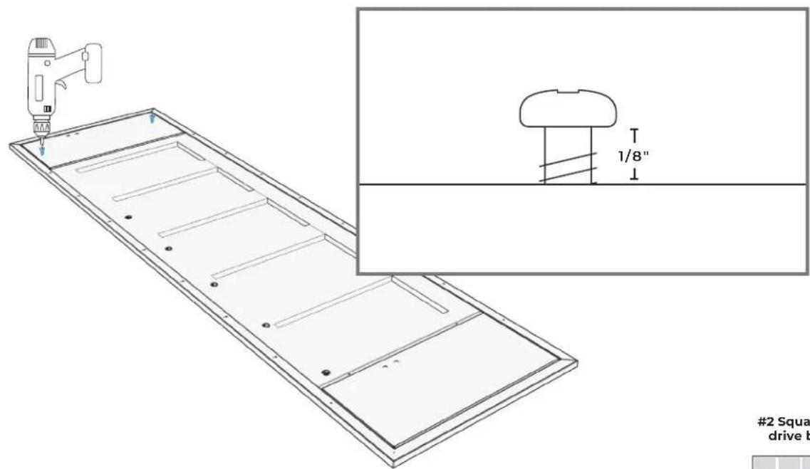
13.7
ENSURE SPACE OF 1/8" (3.2 MM).
text_image
1/8" #2 Square drive bitP ∧ N E I.
STAINLESS STEEL PREPARATION
14.1
natural_image
Line drawing of a refrigerator interior showing front and rear shelves with doorways (no text or symbols)

COMPLETE ALL STEPS FOR EACH UNIT.
14.2
PLACE PANEL FACE-DOWN.

natural_image
Technical line drawing of a rectangular metal frame with internal compartments and mounting holes (no text or symbols)

PLACE ON A FLAT, COVERED SURFACE
14.3
DRIVE FASTENERS INTO PRE-DRILLED LOCATIONS.

natural_image
Technical line drawing of a rectangular panel with internal compartments and a tool in the top-right corner (no text or symbols)2 Square drive bit

14.4
ENSURE SPACE OF 1/8" (3.2 MM).
text_image
#2 Squa drive b2 Square drive bit
P ∧ N E I.
HANG AND ALIGN
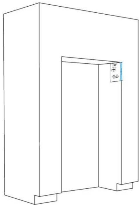
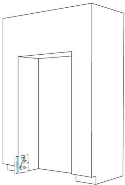
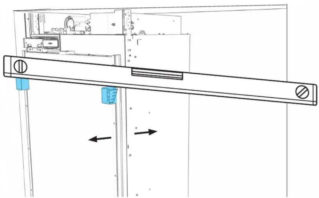
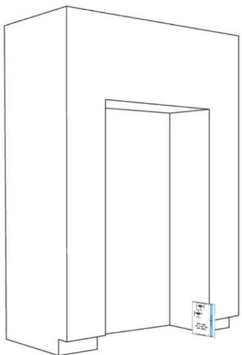
15.1
EACH COLUMN: INSERT FASTENERS INTO TOP SLOTS OF DOOR ADJUSTMENT TRIMS.

natural_image
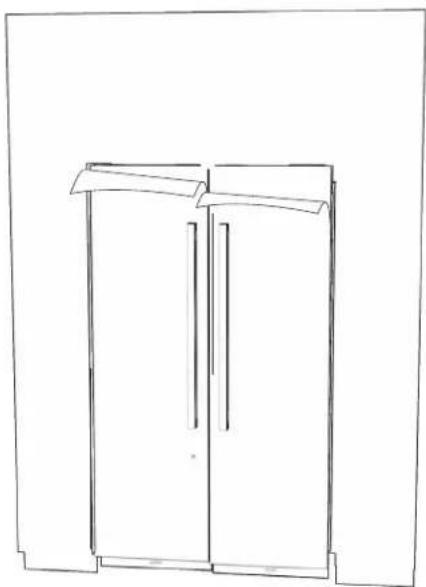
Architectural line drawing of a double door and cabinet with measurement lines (no text or symbols)15.2
EACH COLUMN: MANUALLY ADJUST POSITION OF DOOR PANEL.
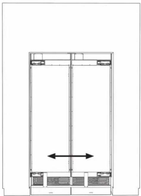
natural_image
Architectural floor plan showing a double door with a central vertical beam and horizontal supports (no text or labels)
natural_image
Line drawing of a mechanical device with a blue component, no text or symbols present
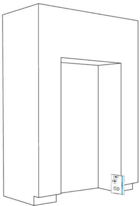
15.3
EACH COLUMN: TIGHTEN TOP TWO FASTENERS.

natural_image
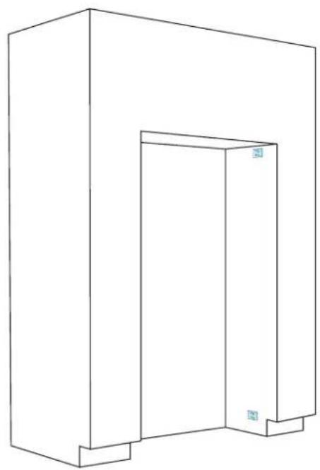
Technical line drawing of a mechanical assembly with labeled components (L, R) and a blue inset view showing a close-up of a door mechanism (no text or symbols beyond labels)15.4
EACH COLUMN: LOOSELY DRIVE IN TWO BOTTOM FASTENERS.
natural_image
Technical line drawing of a door frame assembly with blue adjustment knobs and a blue panel inset (no text or symbols)15.5
EACH COLUMN: LOOSEN THE SIX ADJUSTMENT SCREWS PER SIDE.
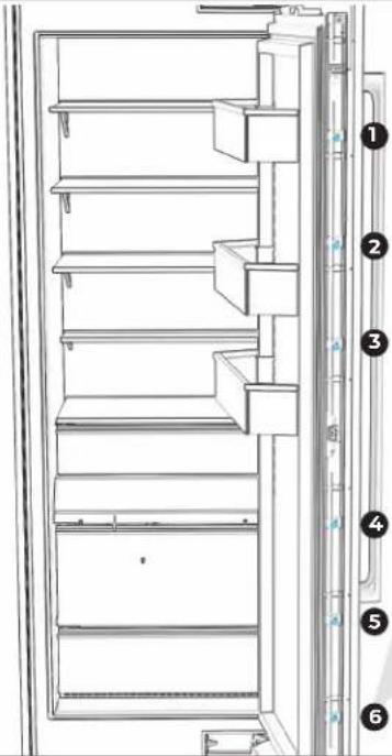
text_image
Technical diagram of a refrigerator with numbered parts for identification
natural_image
Line drawing of a mechanical device with a blue circular component and textured base (no text or symbols)

USE RIGHT-ANGLE ADAPTER FOR GREATER EASE.
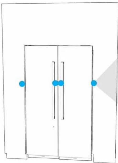
15.6
EACH COLUMN: ADJUST DOOR PANEL HEIGHT UP AND DOWN.
natural_image
Simple line drawing of a door with blue dots and a shaded triangular area (no text or symbols)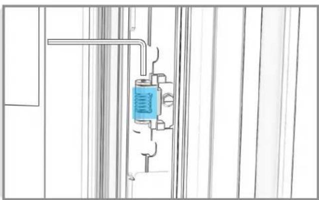
natural_image
Technical line drawing of a mechanical assembly with a blue spring component inserted into a housing (no text or symbols)3 mm Allen
wrench
15.7
EACH COLUMN: ADJUST DEPTH OF DOOR PANEL.
natural_image
Pure architectural floor plan lines without any text, numbers, or symbols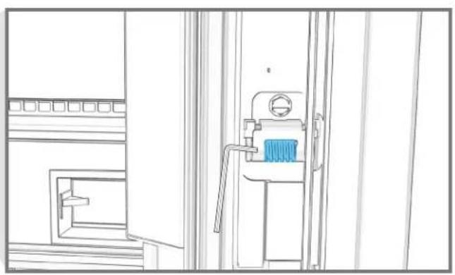
natural_image
Line drawing of a mechanical device with a blue component, no text or symbols present3 mm Allen wrench
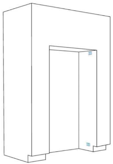
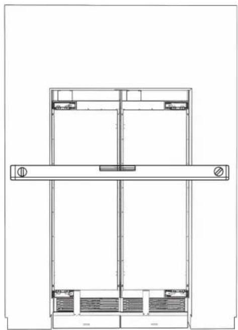
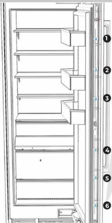
15.8
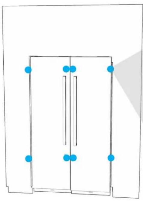
EACH COLUMN: CHECK THAT DOOR PANELS ARE IN PLANE WITH FURNITURE AND EACH OTHER.
natural_image
Architectural floor plan showing two rectangular structures with horizontal beams and internal compartments (no text or labels)
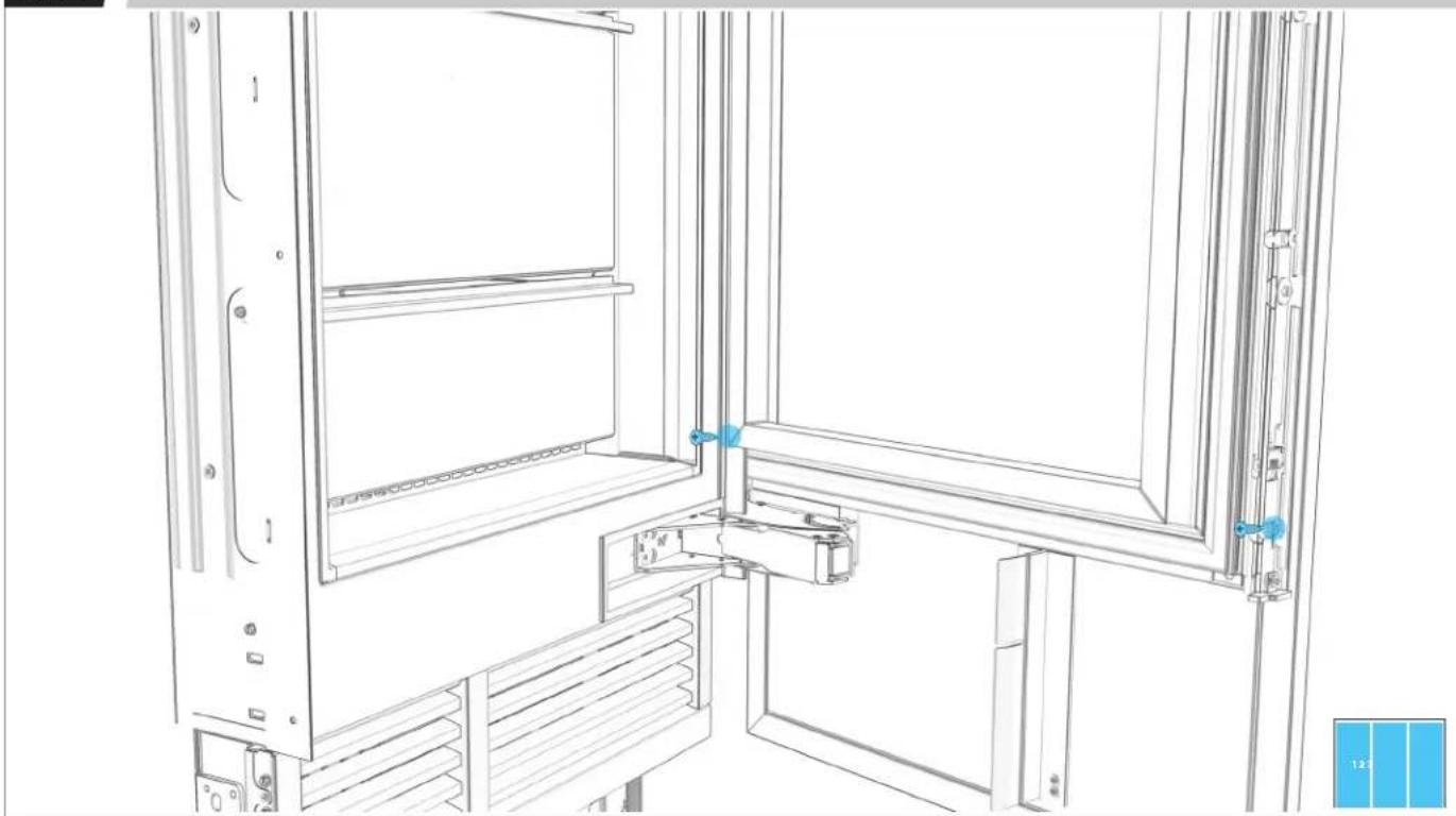
15.9
EACH COLUMN: INSERT AND TIGHTEN ALL 16 FASTENERS.
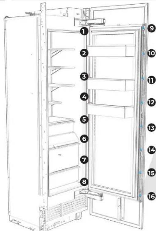
text_image
Diagram of a refrigerator interior with numbered labels pointing to different compartments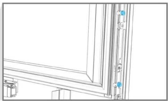
natural_image
Architectural line drawing of a window frame with door and door joints, showing structural details (no text or symbols)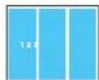
15.10
EACH COLUMN: TIGHTLY SECURE DOOR PANEL.
text_image
Technical diagram of a refrigerator with numbered parts for identification
natural_image
Technical line drawing of a mechanical component with a blue circular feature on the left side (no text or symbols)
15.11
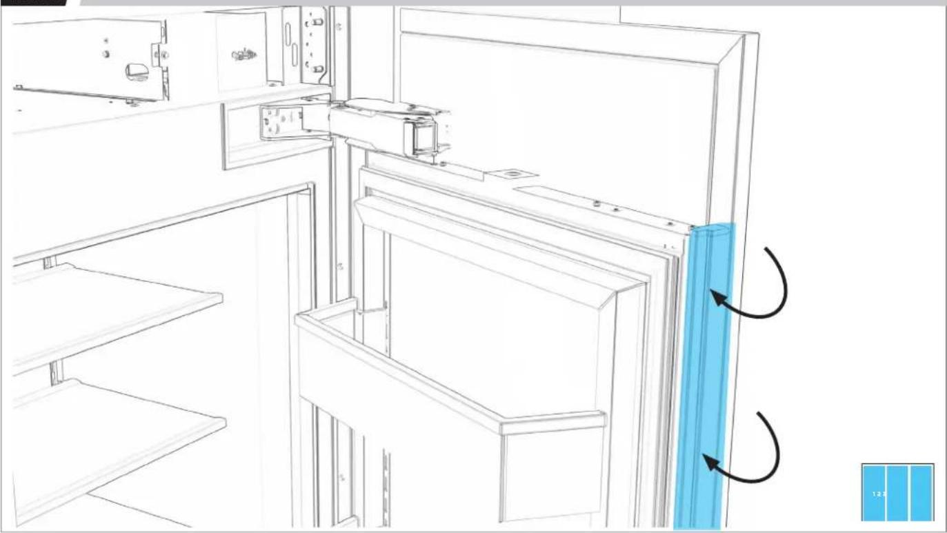
EACH COLUMN: REINSTALL BRACKET TRIMS.
natural_image
Line drawing of a refrigerator interior with door, shelf, and door panel (no text or symbols)COMPLETE
INSTALLATION
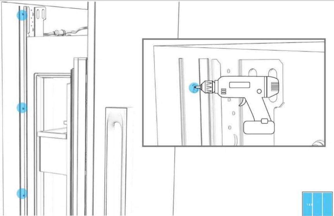
16.1
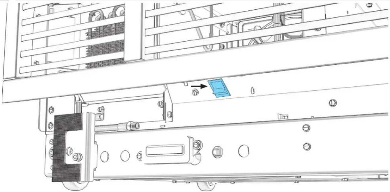
EACH COLUMN: TIGHTEN SCREWS TO DRAW SIDE TRIM TIGHT ON EACH SIDE.
natural_image
Line drawing of a refrigerator shelf with an electric drill in the background (no text or symbols)16.2
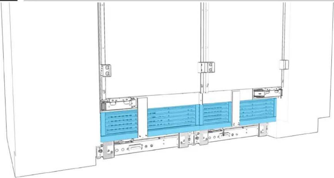
EACH COLUMN: SECURE AIR DIVIDERS TO DOOR PANELS.
text_image
5 mm driver bit 1.2316.3
EACH COLUMN: REMOVE FILM.
natural_image
Line drawing of a two-decker cabinet or wardrobe with two doors and a shelf top (no text or symbols)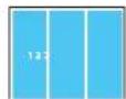
BEFORE FINAL CHECK, READ WARNING.
WARNING
Electrical Shock Hazard
Plug into a grounded 3 prong outlet.
Do not remove ground prong.
Do not use an adapter.
Do not use an extension cord.
Failure to follow these instructions can result in death, fire, or electrical shock.
FINAL CHECK
☐ All packaging removed from the residence
☐ Columns plugged in, powered on and operating at peak performance
□ Columns leveled
☐ Panels aligned and rechecked after 20 minutes operation
□ Water supplies properly connected with no leaks
□ Water filters installed (not applicable with reverse osmosis system)
□ Water dispensers and/or ice makers working
□ Any problems with installation or parts reported to JennAir Epicenter
OWNER WALKTHROUGH
If the owner is present, provide them with the User Guide. Guide the owner through:
□ Control panel functions
□ App and WiFi setup
□ Discarding first few batches of ice
□ Replacing the water filters
□ Registering their columns
☐ How to contact JennAir Epicenter through jennair.com or at 1-800-JENNAIR (536-6247)
natural_image
Pure geometric diagram with four rectangles and curved lines, no text or symbols presentnatural_image
Pure geometric diagram with lines and arrows, no text or symbols presentnatural_image
Pure geometric diagram with four squares and curved arrows, no text or symbols presentnatural_image
Pure geometric diagram with four squares and curved lines, no text or symbols presentnatural_image
Line drawing of a mechanical bracket with two circular holes (no text or symbols)natural_image
Simple line drawing of a rectangular electronic component with parallel leads and a pointer (no text or symbols)Tapis chauffant à pellicule autocollante (W10912090)
natural_image
Technical line drawing of a metal bracket with mounting holes (no text or symbols)Bride de soffite Badass (W1111754)
natural_image
Line drawing of a metal bracket with slots and holes (no text or symbols)natural_image
Simple line drawing of a mechanical lifting device with two vertical supports (no text or symbols)
natural_image
Simple line drawing of two hanging objects with blue handles, no text or symbols present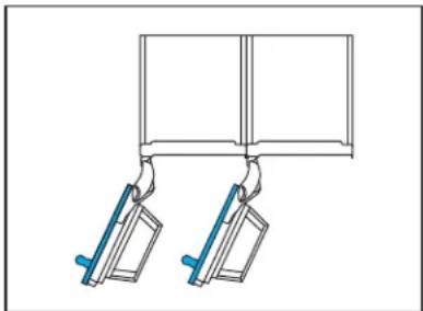
natural_image
Diagram of two mechanical clamps hanging from a rectangular frame (no text or symbols)CONFIGURATIONS À 2 APPAREILS NON PERMISES
natural_image
Diagram of a mechanical assembly with a blue internal component and a labeled X (no text or symbols on the diagram itself)CONFIGURATIONS
3 APPAREILS
CONFIGURATIONS À 3 APPAREILS PERMISES
natural_image
Pure diagram of three hanging metal objects with blue connectors, no text or symbols presentnatural_image
Pure diagram of three hanging objects with blue handles, no text or symbols presentnatural_image
Pure diagram of a mechanical lifting or clamping mechanism without any text, numbers, or symbolsCONFIGURATIONS À 3 APPAREILS NON PERMISES
natural_image
Diagram showing two mechanical lifting devices with a tool, no text or symbols present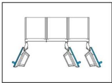
natural_image
Simple line drawing of a three-panel hanging structure with two hanging weights (no text or symbols)natural_image
Diagram showing two mechanical clamps hanging from a rectangular frame, with no text or symbols present.DIMENSIONS
PRODUIT
DIMENSIONS COMPLÈTES (SANS PANNEAU)
flowchart
graph LR
    A[" "] --> B[" "]
    B --> C[" "]
    C --> D["Meuble"]
DIMENSIONS
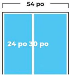
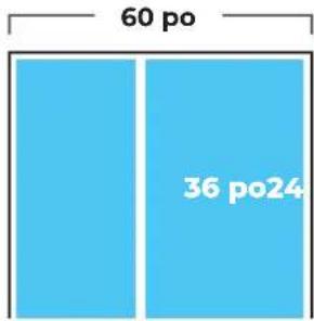
OUVERTURE
CONFIGURATION À 2 APPAREILS
bar
| Category | Value (points) | |---|---| | Top Section | 54 | | Bottom Section | 18 | | Bottom Section | 66 |LARGEUR DE L'OUVERTURE
text_image
54 po 24 po 30 poLARGEUR DE L'OUVERTURE
text_image
60 po 36 po24LARGEUR DE L'OUVERTURE
text_image
60 po 0 po 30 poLARGEUR DE L'OUVERTURE
text_image
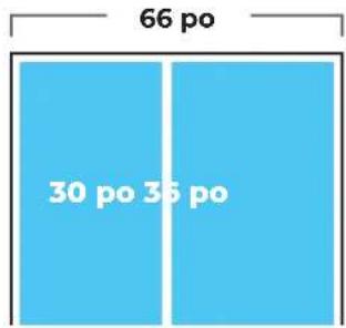
66 po 30 po 36 poLARGEUR DE L'OUVERTURE
text_image
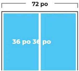
72 po 36 po 36 poDIMENSIONS
OUVERTURE
CONFIGURATION À 3 APPAREILS
natural_image
Three vertical gray panels with a white number '123' in the top-left corner, no other text or symbols present.natural_image
3D diagram of a vertical blue structure with two upward arrows, mounted on a base platform (no text or symbols)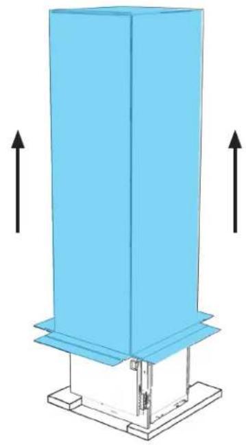
natural_image
3D diagram of a vertical blue structure mounted on a base with two upward arrows indicating direction (no text or symbols)

RETIRER LES TROUSSES D'INSTALLATION DU TIROIR DES TIROIRS POUR SPÉCIALITÉ PENDANT QUE L'APPAREIL EST TOUJOURS SUR SES PATINS.
AVANT DE DÉPLACER L'APPAREIL, LIRE TOUS LES AVERTISSEMENTS.
⚠️ AVERTISSEMENT
natural_image
3D wireframe diagram of a blue industrial cabinet or enclosure with mounting brackets (no text or symbols)

DÉPLACER L'APPAREIL À DEUX PERSONNES. NE PAS OUVRIR LES PORTES AVANT QUE L'APPAREIL SOIT SÉCURISÉ.
1.3
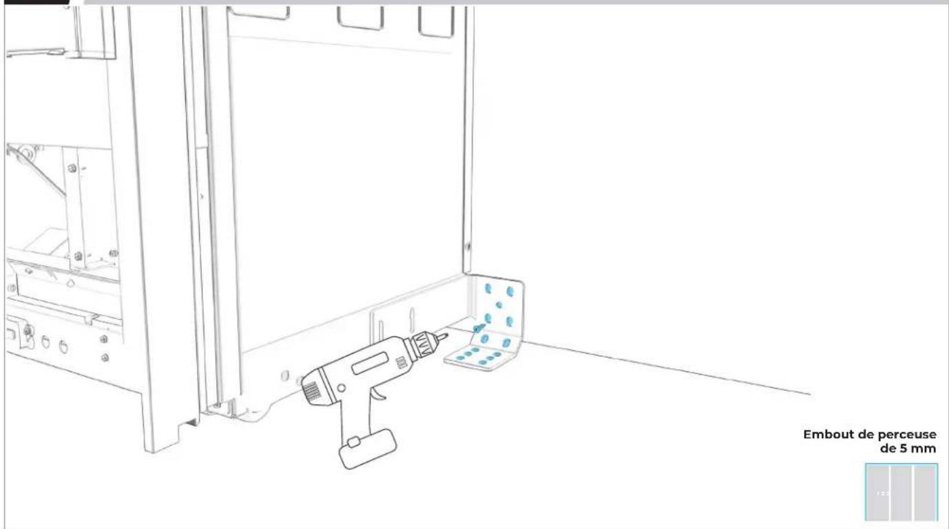
POUR CHAQUE APPAREIL : ENLEVER LES DEUX VIS DU FILTRE À EAU.
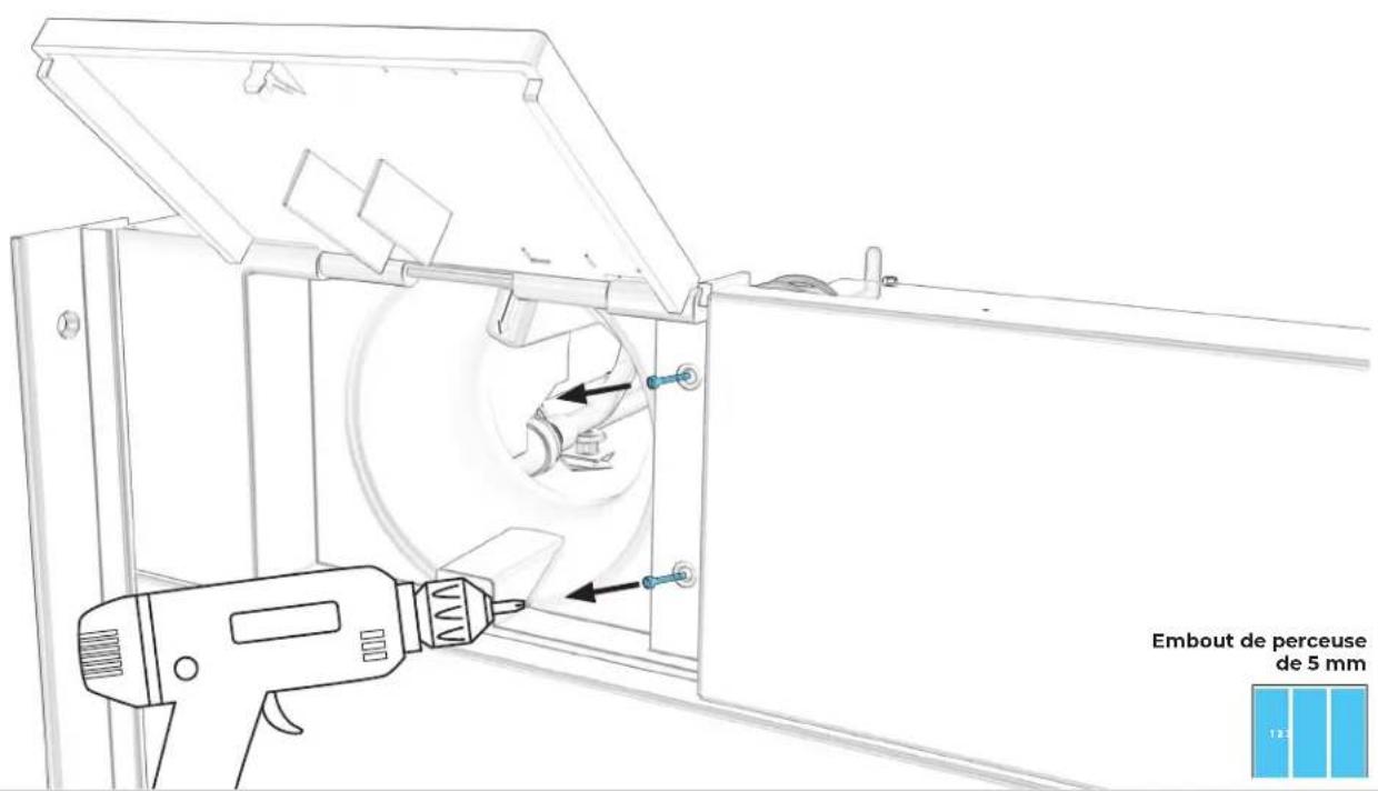
text_image
Embout de perceuse de 5 mm1.4
POUR CHAQUE APPAREIL : TIRER VERS LA GAUCHE, ENLEVER LA PLAQUE.
text_image
Technical diagram of a mechanical assembly with labeled components and directional arrows indicating motion or movement.1.5
POUR CHAQUE APPAREIL : TIRER LE BOÎTIER VERS LA DROITE POUR L'ENLEVER.
natural_image
Technical line drawing of a mechanical assembly with blue component and mounting holes (no text or symbols)1.6
POUR CHAQUE APPAREIL : RETIRER LES QUATRE VIS DE LA GRILLE D'AÉRATION.
text_image
Embout de perceuse de 5 mm1.7
POUR CHAQUE APPAREIL : RETIRER LA GRILLE D'AÉRATION DE LA BASE.
text_image
Technical diagram of a server rack with labeled components and numbered parts1.8
DEUXIÈME (ET TROISIÈME) APPAREIL : INSTALLER LA GARNITURE DE GRILLE D'AÉRATION.
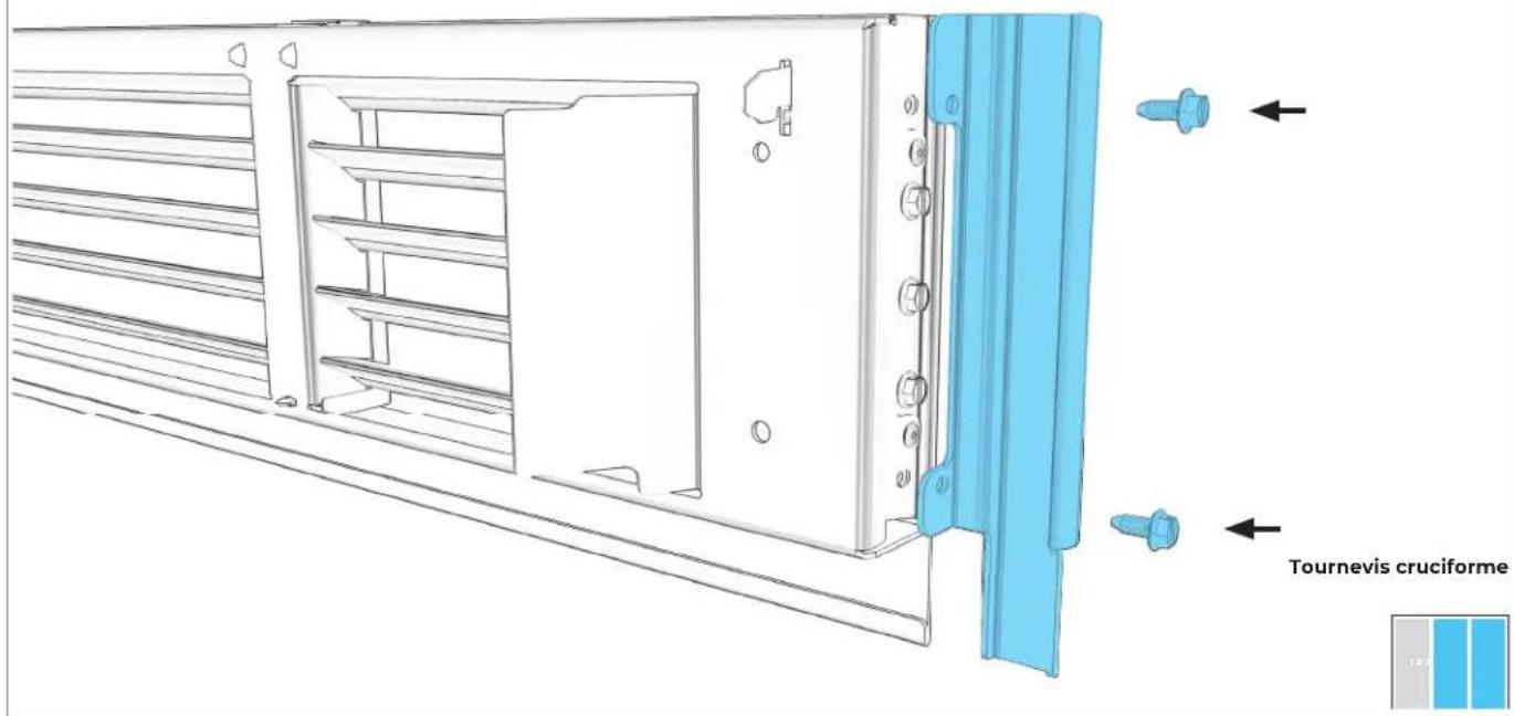
text_image
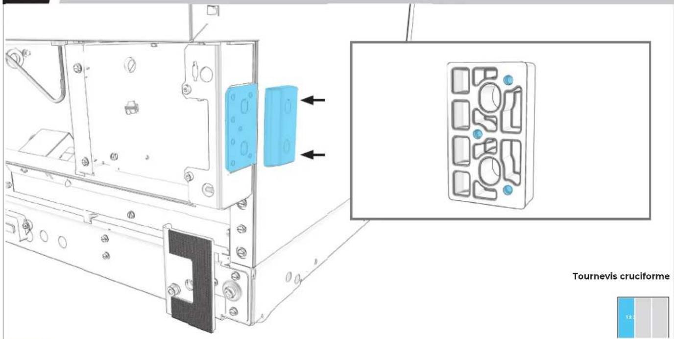
Tournevis cruciforme1.9
RETIRER LES GARNITURES ENTRE LES APPAREILS.
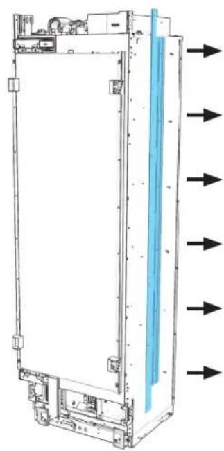
natural_image
Diagram of a server rack with directional arrows indicating flow or movement (no text or symbols present)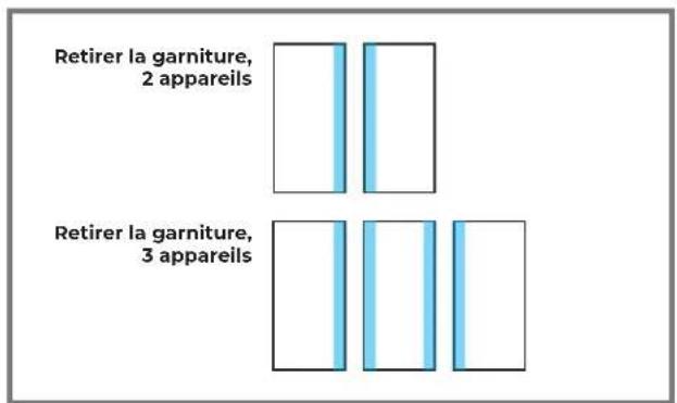
text_image
Retirer la garniture, 2 appareils Retirer la garniture, 3 appareils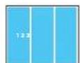

LAISSER LES GARNITURES EN PLACE SUR LES CÔTÉS MEUBLES.
1.10
PREMIER APPAREIL : INSTALLER L'ESPACEUR.
text_image
Tournevis cruciforme 12.5

S'ASSURER QUE LE CÔTÉ MINCE FAIT FACE VERS L'EXTÉRIEUR.
1.11
SI TROIS APPAREILS SONT INSTALLÉS : RÉPÉTER L'ÉTAPE 1.10 POUR LE DEUXIÈME APPAREIL.

natural_image
Technical line drawing of a mechanical assembly with mounting brackets and a blue component, no visible text or symbolsTournevis cruciforme

PRÉPARATION
DE LA TROUSSE DE JOINT
2.1
PREMIER APPAREIL : ALIGNER ET FIXER L'ÉLÉMENT CHAUFFANT.
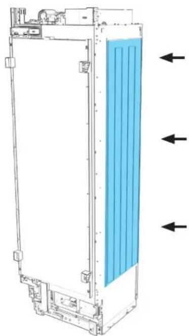
natural_image
Technical line drawing of a vertical panel or enclosure with internal blue insulation and directional arrows indicating flow or movement (no text or symbols present)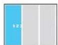
2.2
BRANCHER L'ÉLÉMENT CHAUFFANT SUR L'APPAREIL.
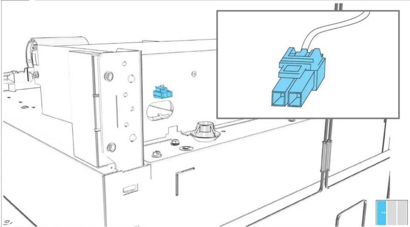
natural_image
Technical line drawing of a mechanical assembly with blue plastic connectors and a close-up inset showing the same component (no text or symbols present)2.3
RÉPÉTER L'ÉTAPE 2.1 ET 2.2 AVEC LE DEUXIÈME APPAREIL.

natural_image
Technical line drawing of a vertical industrial or cooling unit with blue insulation material, showing internal components and directional arrows (no text or symbols)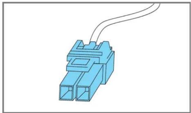
natural_image
Blue 3D connector with two ports and a coiled cable (no text or symbols)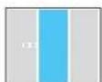
2.4
PREMIER APPAREIL : INSTALLER LA GARNITURE DE JOINT EN L.
natural_image
Technical line drawing of a vertical panel or enclosure with directional arrows indicating flow or movement (no text or symbols present)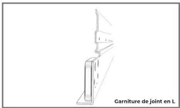
natural_image
Line drawing of a structural joint with label 'Garniture de joint en L' (no other text or symbols)Tournevis cruciforme
2.5
DEUXIÈME APPAREIL : INSTALLER LA GARNITURE DE JOINT EN CROCHET.
natural_image
Diagram of a refrigerator interior with blue liquid and directional arrows indicating flow or movement (no text or symbols)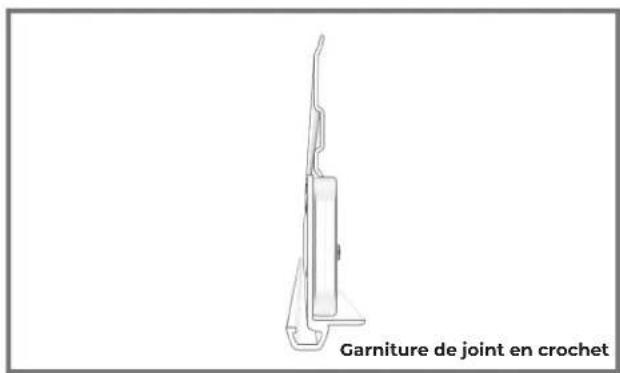
text_image
Garniture de joint en crochetTournevis cruciforme
2.6
SI TROIS APPAREILS SONT INSTALLÉS : INSTALLER LE JOINT DE GARNITURE EN L SUR LE DEUXIÈME APPAREIL.
natural_image
Technical line drawing of a vertical electronic device with mounting brackets and a blue panel, showing directional arrows (no text or symbols)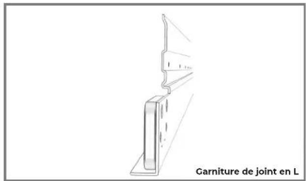
text_image
Garniture de joint en LTournevis cruciforme
2.7
SI TROIS APPAREILS SONT INSTALLÉS : INSTALLER LE JOINT DE GARNITURE EN CROCHET SUR LE TROISIÈME APPAREIL.
natural_image
Diagram of a refrigerator interior with blue liquid and directional arrows indicating flow or movement (no text or symbols)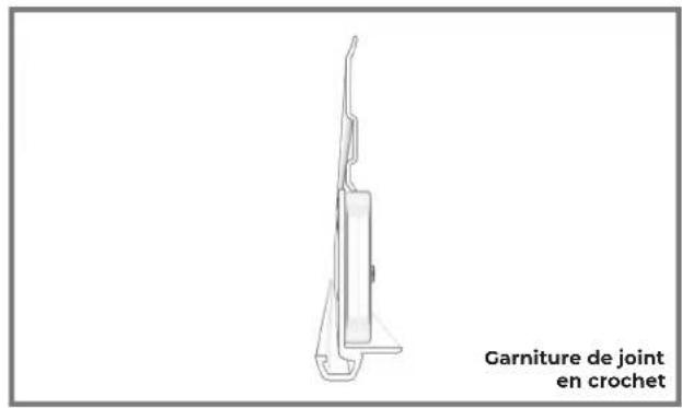
text_image
Garniture de joint en crochetTournevis cruciforme
PRÉPARATION
DE LA BRIDE DE POSITIONNEMENT
3.1
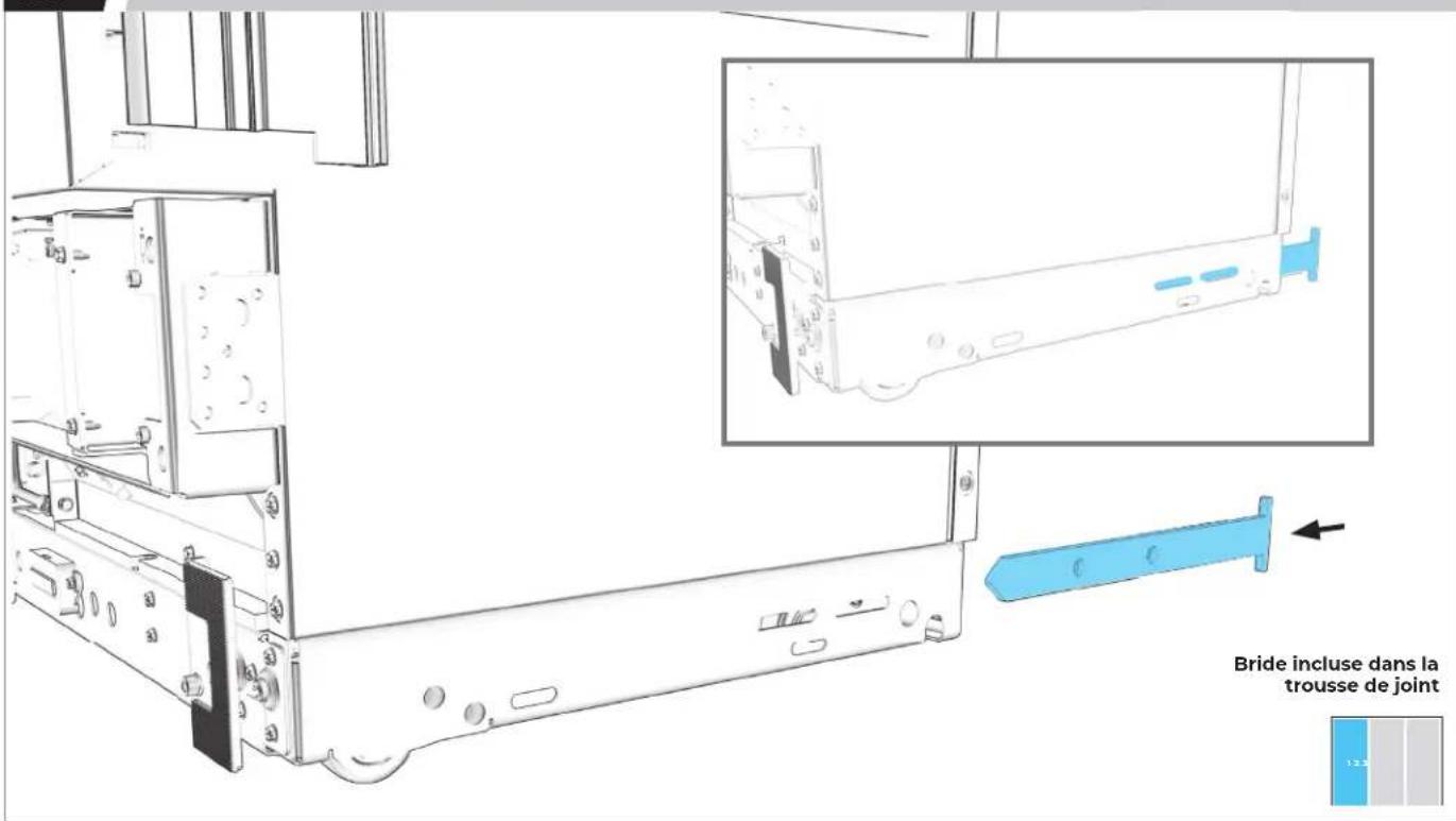
PREMIER APPAREIL : GLISSER LA BRIDE DANS LA FENTE D'INSTALLATION.
natural_image
Technical line drawing of a computer monitor internal frame with a blue handheld device inserted (no text or symbols)Douille M6

LA POSITION FINALE EST DÉTERMINÉE UNE FOIS LES APPAREILS ENTIÈREMENT SOULEVÉS.
3.5
SI TROIS APPAREILS SONT INSTALLÉS : RÉPÉTER LES ÉTAPES 3.1 À 3.4 POUR LE DEUXIÈME APPAREIL.

natural_image
Technical line drawing of a computer monitor with an electric drive and cable attachment (no text or symbols)Douille M6
INSTALLATION DE LA BRIDE
B A D A S S
4.1
MARQUE UNE LIGNE À LA LARGEUR DU PREMIER APPAREIL, À PARTIR DU CADRE DE GAUCHE.
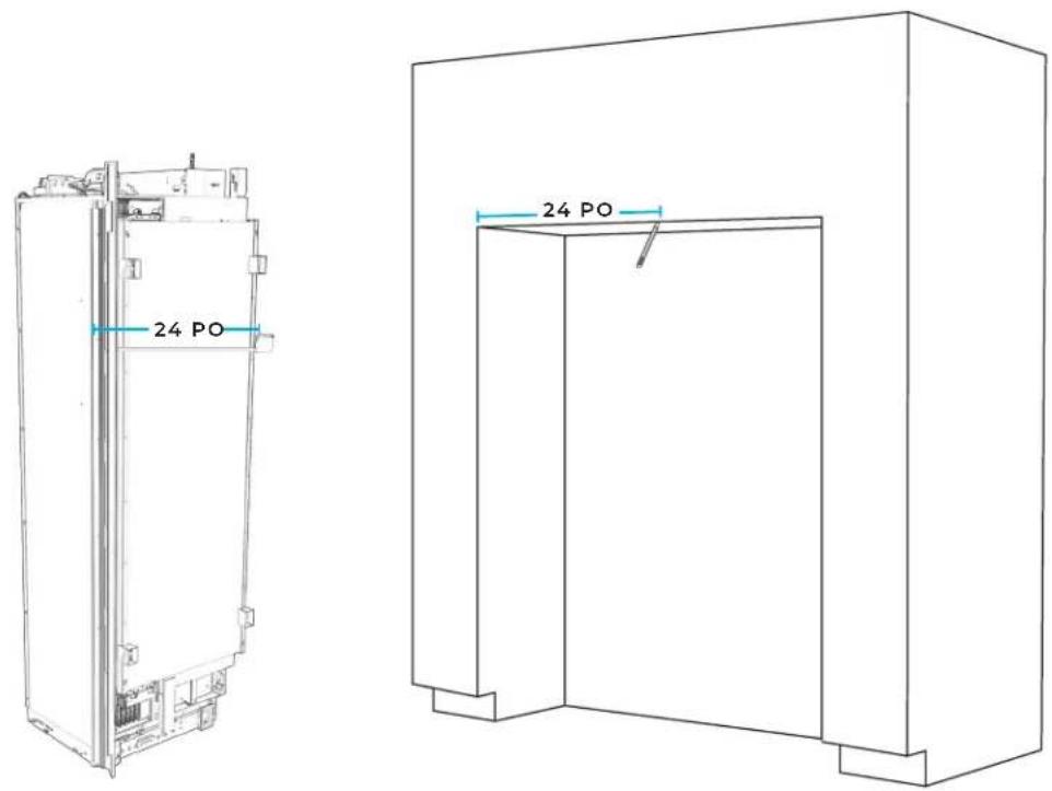
text_image
24 PO 24 PO
4.2
À L'AIDE D'UNE ÉQUERRE, TRACER UNE LIGNE PERPENDICULAIRE AU CADRE DE DEVANT.
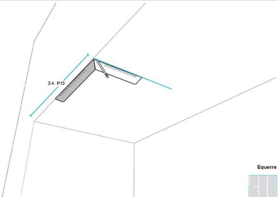
text_image
24 PO Équerre4.3
ALIGNER LA FENTE CENTRALE DU GABARIT DE BRIDE AVEC LA LIGNE DE LARGEUR.
text_image
① ② ③ ④ ⑤ ⑥ ⑦4.4
ALIGNER LA LIGNE DU TYPE DE PORTE DÉJÀ SÉLECTIONNÉ AVEC LE DEVANT DE L'ARMOIRE.
text_image
Diagram showing a 3D coordinate system with labeled axes and a rectangular box containing mathematical expressions.4.5
MARQUER DEUX LIGNES.
text_image
Technical diagram showing a 3D coordinate system with labeled axes and a magnified inset of a plane, likely illustrating a geometric or spatial concept.4.6
ALIGNER LA BRIDE.
natural_image
Pure technical line drawing of a mechanical bracket or bracket without any text, numbers, or symbols4.7
ALIGNER LES POINTS DES TROUS EN FORME DE DIAMANT ET LA LIGNE DE LARGEUR.
natural_image
Pure technical diagram of a container with internal compartments and circular holes, no text or symbols present
4.8
FIXER SANS SERRER LA BRIDE AU SOFFITE.
natural_image
Line drawing of a hand holding a power tool against a wall-mounted panel (no text or symbols)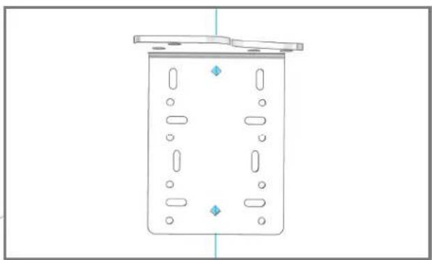
natural_image
Simple line drawing of a rectangular container with internal compartments and a lid, no text or symbols present.natural_image
Technical line drawing of a rectangular container with internal compartments and mounting points (no text or symbols)
4.10
SERRER 8 VIS.
natural_image
Technical line drawing of a mechanical device mounted on a wall, with an inset showing its internal components (no text or symbols present)Vis à bois

UTILISER DES VIS À BOIS D'UNE LONGUEUR CONVENABLE
4.11
FIXER LA BRIDE À L'ARMOIRE EN UTILISANT LES TROUS RONDS.
natural_image
Pure architectural line drawing of a building facade with three metal bracket symbols (no text or labels)PRÉPARATION
DU MEUBLE
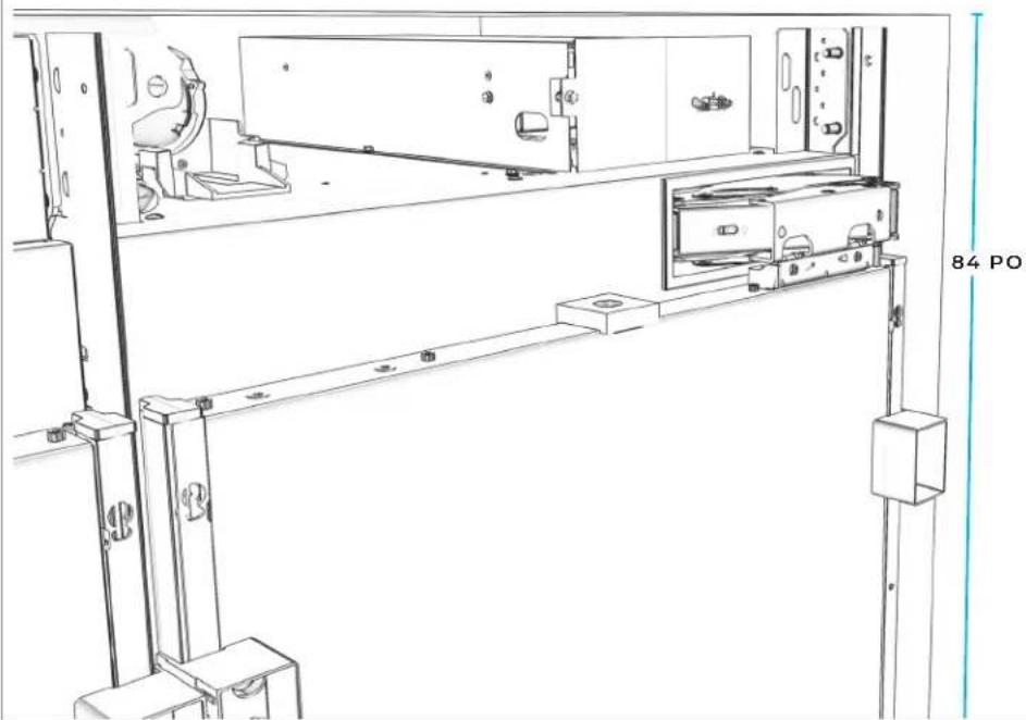
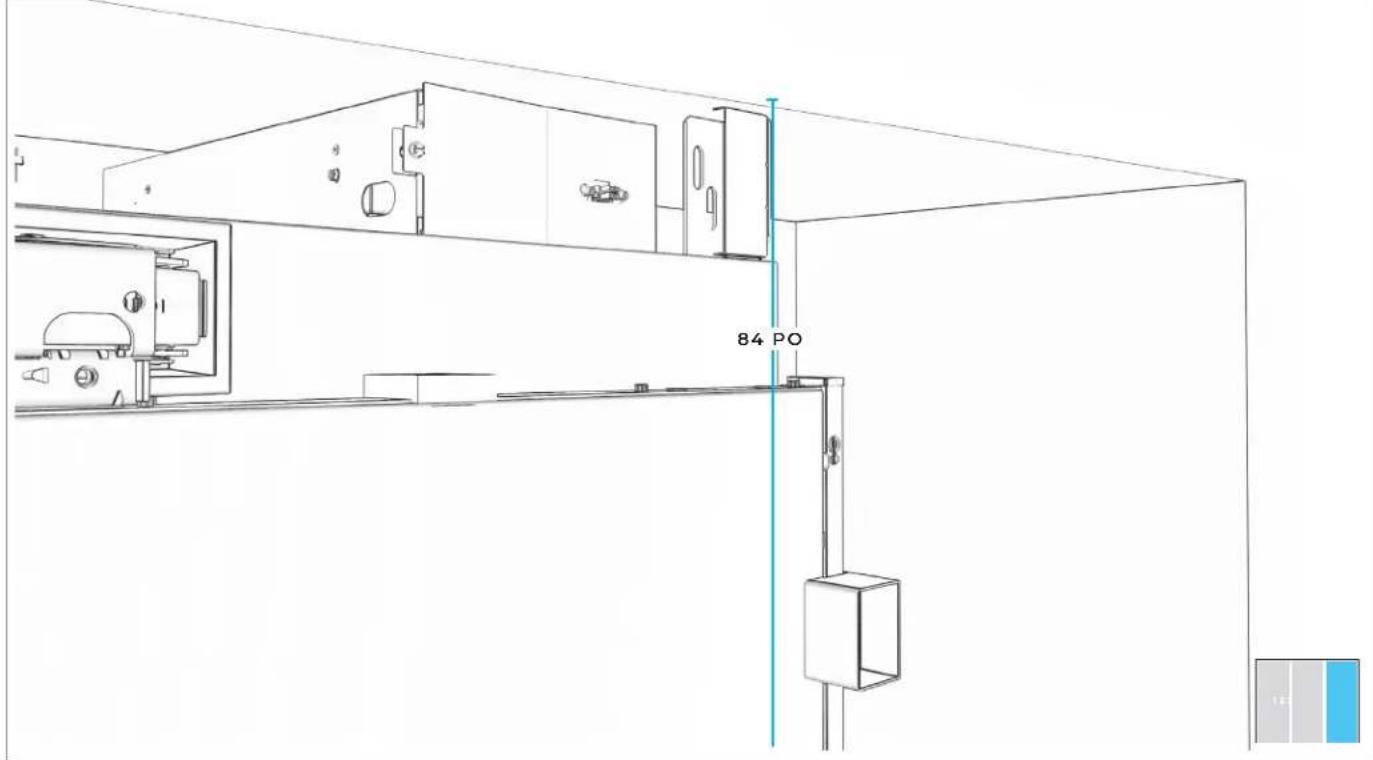
5.1
MESURER ET MARQUER UNE LIGNE POUR LE PANNEAU DE GAUCHE.
text_image
84 PO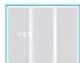
5.2
PLACER LE GABARIT SUR LE PANNEAU DE GAUCHE.

natural_image
Line drawing of a simple 3D rectangular structure with a blue label on the top right corner (no text or symbols on the structure itself)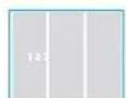
5.3
ALIGNER LA LIGNE DE STYLE DE PORTE AVEC LE DEVANT DE L'ARMOIRE ET MARQUER LES LIGNES D'ALIGNEMENT.
natural_image
Line drawing of a 3D rectangular structure with a small blue label on the top left corner (no text or symbols on the main diagram)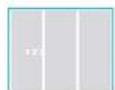
5.4
RÉPÉTER LES ÉTAPES 5.1 À 5.3 POUR LE PANNEAU DE DROITE.

natural_image
Line drawing of a simple 3D architectural structure with a door and corner brackets (no text or symbols)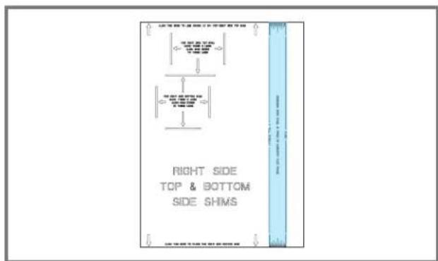
text_image
RIGHT SIDE TOP & BOTTOM SIDE SHIMS
5.5
PLACER ET ALIGNER LE GABARIT SUR LA SECTION INFÉRIEURE DU PANNEAU DE GAUCHE, MARQUER LES LIGNES D'ALIGNEMENTS DE CALES.

natural_image
Line drawing of a simple 3D rectangular structure with a small inset image showing a label 'A' (no text or symbols on the main diagram)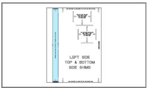
text_image
LEFT SIDE TOP & BOTTOM SIDE SHIMS
5.6
RÉPÉTER L'ÉTAPE 5.5 POUR LE PANNEAU DE DROITE.
natural_image
Line drawing of a 3D rectangular structure with a vertical door and base, no text or symbols present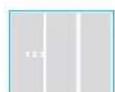
5.7
SÉPARER LES CALES ROTTER EN RESPECTANT LES LONGUEURS.

natural_image
Line drawing of a simple 3D rectangular structure with a vertical door and corner supports (no text or symbols)
text_image
9/32" 1/4" 3/16"1/8" 1/16"
5.8
AJOUTER DES CALES AU BESOIN.
natural_image
Line drawing of a 3D rectangular structure with a vertical door and corner supports (no text or symbols)
natural_image
Pure architectural floor plan lines without any text, numbers, or symbols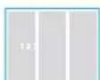
5.9
FIXER LES CALES AUX PANNEAUX LATÉRAUX (DEUX VIS REQUISES).

natural_image
Line drawing of a 3D rectangular enclosure with a door and wall, no text or symbols presentVis à bois

UTILISER DES VIS À BOIS D'UNE LONGUEUR CONVENABLE
5.10
UTILISER DU RUBAN ADHÉSIF POUR FIXER LE TUYAU D'EAU AU PLANCHER.

natural_image
Line drawing of a 3D rectangular structure with a double door and corner supports, showing no text or symbols.
INSTALLATION DU
PREMIER
APPAREIL
6.1
ÉTEINDRE L'ALIMENTATION.
natural_image
Technical line drawing of a mechanical assembly with no visible text or symbolsAVANT DE BRANCHER L'APPAREIL, LIRE LES AVERTISSEMENTS.
AVERTISSEMENT

natural_image
Line drawing of an electrical outlet with a blue socket and connected to a wire (no text or symbols)AVANT DE DÉPLACER L'APPAREIL, LIRE LES AVERTISSEMENTS.
⚠️ AVERTISSEMENT
natural_image
Technical line drawing of a mechanical device with internal components and directional arrows indicating flow or movement (no text or symbols)

NE PAS ENDOMMAGER LE TUYAU D'EAU.
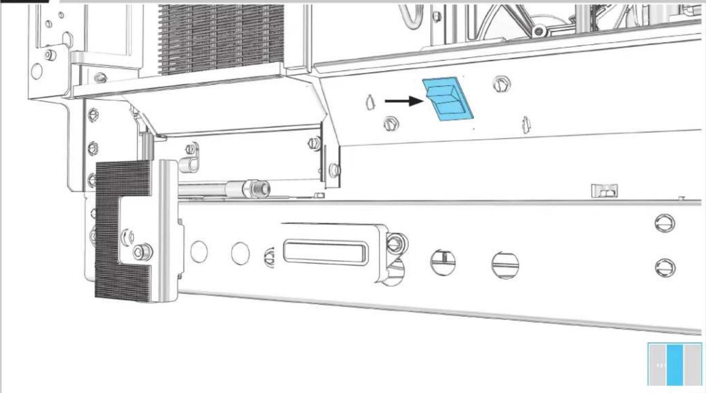
6.4
UTILISER UN GABARIT DE PROFONDEUR (SELON LE STYLE DE PORTE).

natural_image
Technical line drawing of a mechanical or electrical enclosure with two blue rectangular components and internal components (no text or symbols)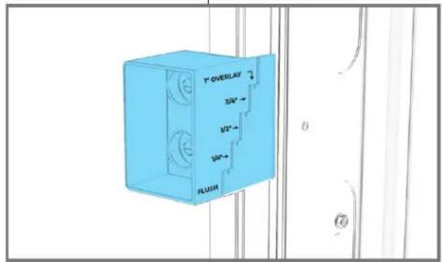
text_image
T" OVERLAY 3/4" 1/2" 1/8" FLUSH
6.5
FAIRE SORTIR LES ROULETTES UNE À UNE.
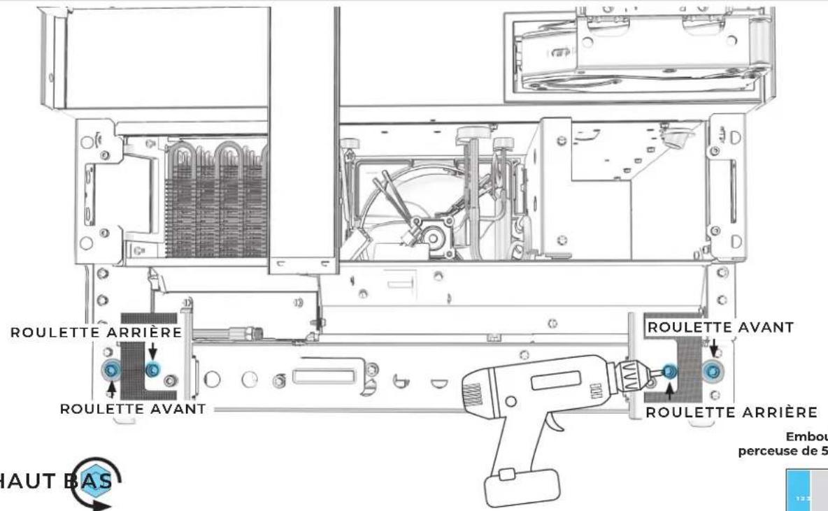
text_image
ROULETTE ARRIÈRE ROULETTE AVANT RAUT BAS ROULETTE AVANT ROULETTE ARRIÈRE Embou perceuse de 5text_image
Technical diagram of an electrical enclosure with labeled components and a 3D preview of the display unit.6.8
AJUSTER LES ROULETTES JUSQU'À CE QUE LES GABARITS DE PROFONDEUR SOIENT IDENTIQUES.
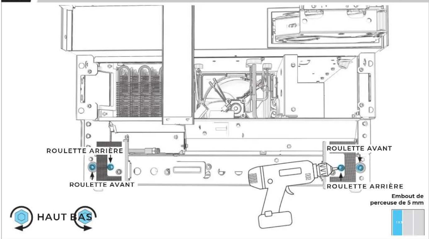
text_image
ROULETTE ARRIÈRE ROULETTE AVANT ROULETTE AVANT ROULETTE ARRIÈRE HAUT BAS Embout de perceuse de 5 mm6.9
PLACER SANS SERRER DES VIS DANS LA BRIDE D'INSTALLATION ET LA BRIDE BADASS DE SOFFITE.
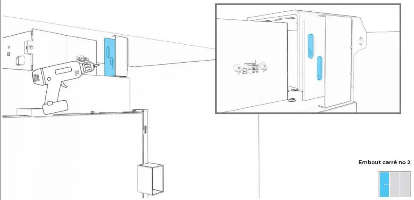
text_image
Embout carré no 2 1.2.56.10
FIXER LA BRIDE D'INSTALLATION SUPÉRIEURE AU MEUBLE.
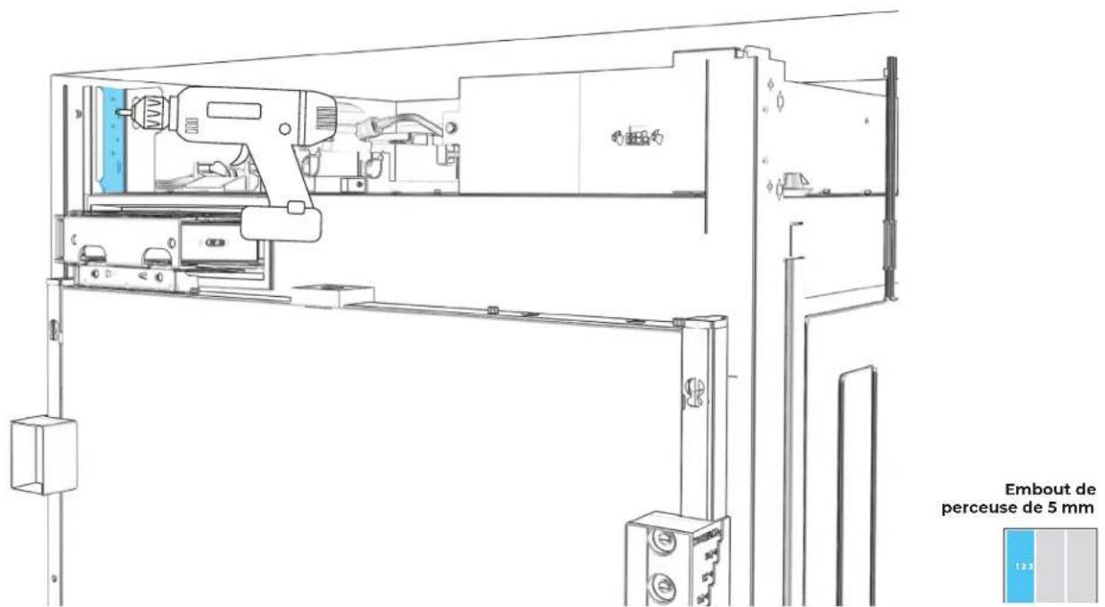
text_image
Embout de perceuse de 5 mm6.11
FIXER LA BRIDE D'INSTALLATION INFÉRIEURE AU MEUBLE.
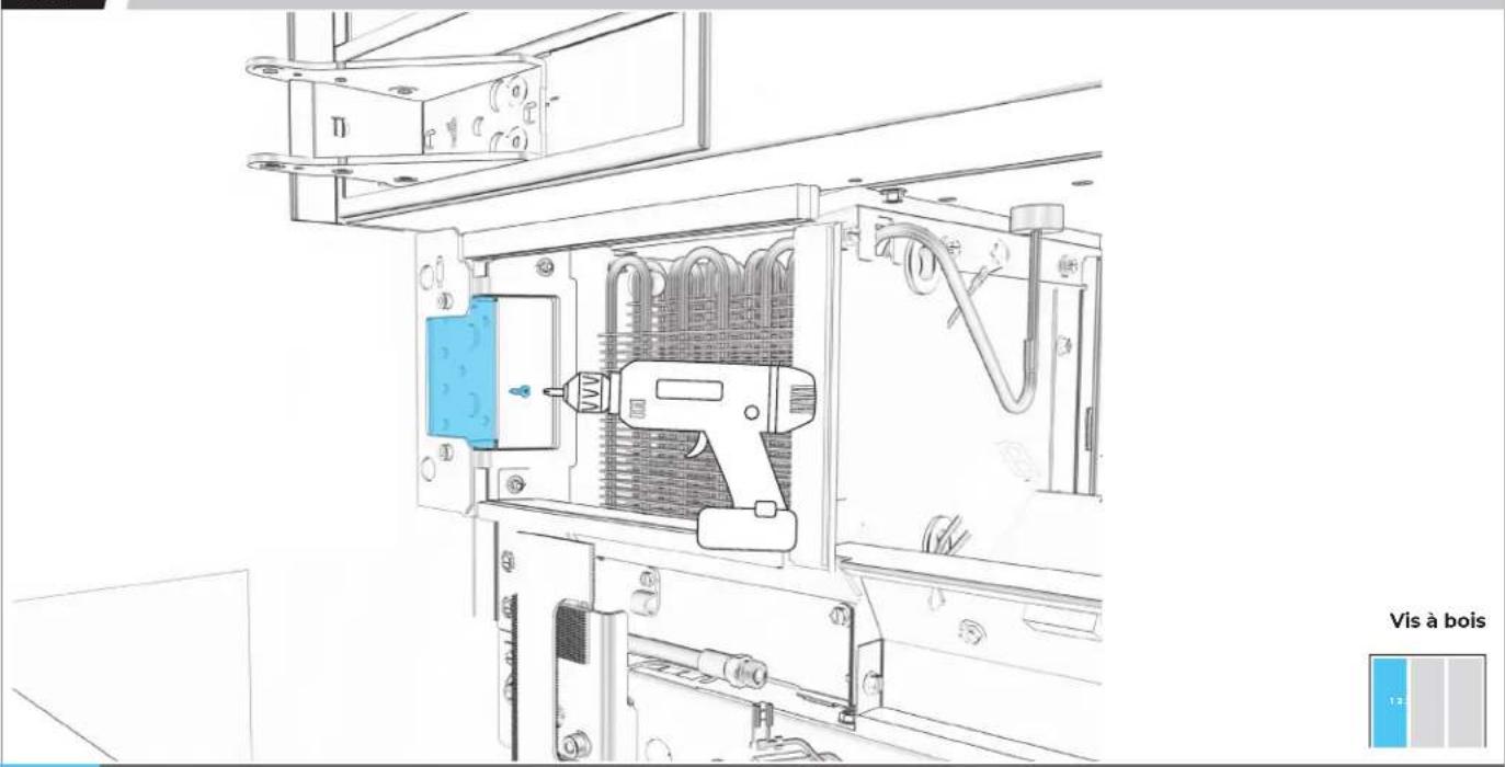
natural_image
Technical line drawing of an electrical enclosure with a tool inside, showing internal components and wiring (no text or symbols)
UTILISER DES VIS À BOIS D'UNE LONGUEUR CONVENABLE.
6.12
PLACER LES BRIDES AU PLANCHER ET AU MUR.
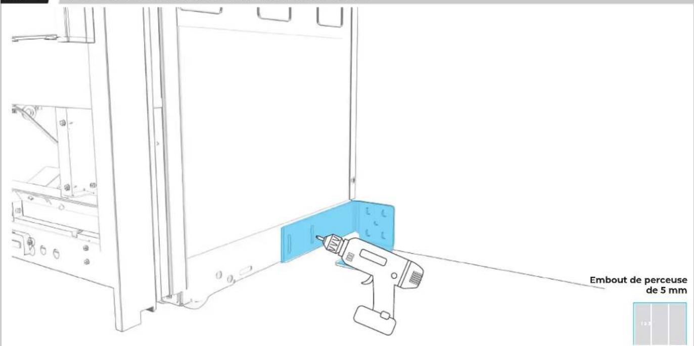
text_image
Embout de perceuse de 5 mm
ÉVALUER LES MATÉRIAUX DE FABRICATION DU MUR ET DU PLANCHER.
6.13
FIXER LA BRIDE DE POSITIONNEMENT EN UTILISANT AUTANT DE FENTES QUE POSSIBLE.
text_image
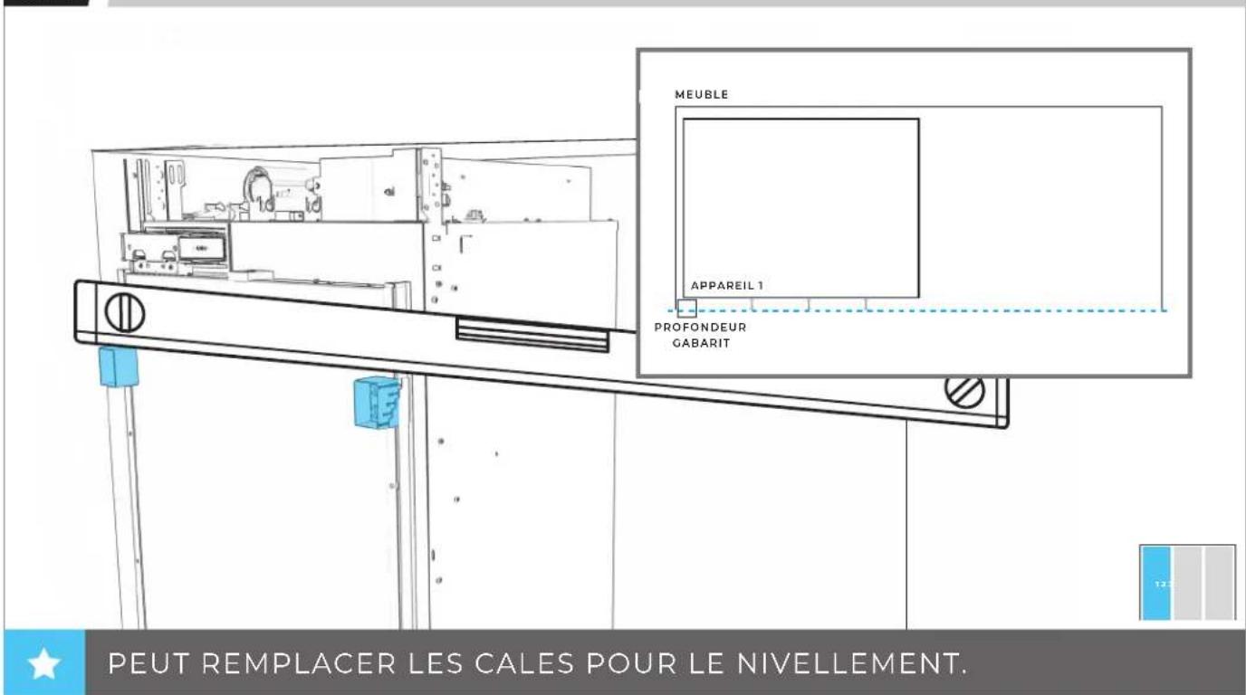
Embout de perceuse de 5 mm6.14
UTILISER UN NIVEAU POUR VÉRIFIER LA PROFONDEUR À PLUSIEURS EMPLACEMENTS À PARTIR DU CADRE DE FACE.
text_image
MEUBLE APPAREIL 1 PROFONDEUR GABARIT PEUT REMPLACER LES CALES POUR LE NIVELLEMENT.6.15
AJUSTER DE NOUVEAU L'APPAREIL POUR QUE TOUTES LES PROFONDEURS CORRESPONDENT.

natural_image
Technical line drawing of a mechanical assembly with no visible text or symbols
INSTALLATION DU
DEUXIÈME
APPAREIL
7.1
ÉTEINDRE L'ALIMENTATION.
natural_image
Technical line drawing of a mechanical assembly with no visible text or symbolsAVANT DE BRANCHER L'APPAREIL, LIRE LES AVERTISSEMENTS.
AVERTISSEMENT

natural_image
Line drawing of a wall socket connected to an electrical outlet plug (no text or symbols)
AVANT DE DÉPLACER L'APPAREIL, LIRE TOUS LES AVERTISSEMENTS.
AVERTISSEMENT
natural_image
Technical line drawing of an electrical enclosure with internal components and mounting holes (no text or symbols)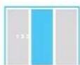
7.4
SI UN TROISIÈME APPAREIL EST INSTALLÉ :
PASSER À LA SECTION 8
7.5
DEUXIÈME APPAREIL : PLACER À LA LIGNE DE 84 po.
natural_image
Technical line drawing of a mechanical assembly with mounting brackets and a door, no text or symbols present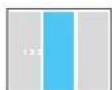
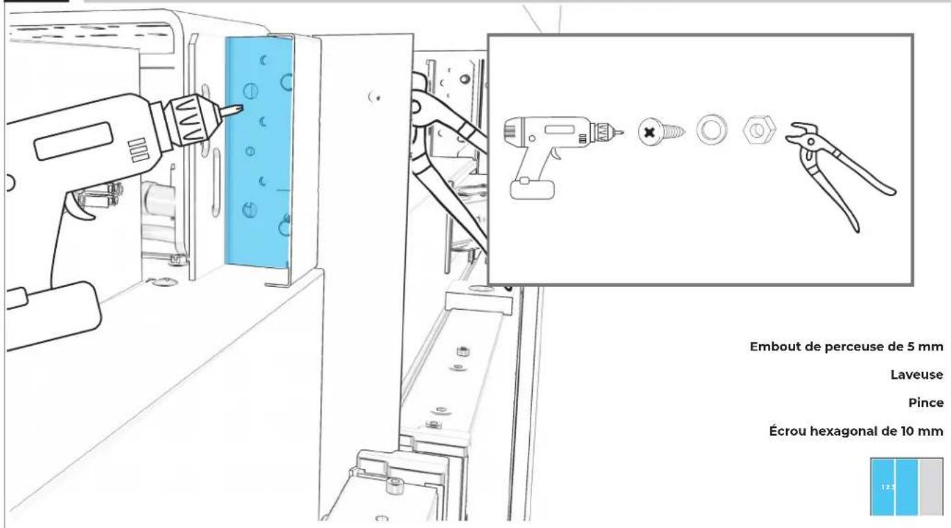
7.6
FIXER LE HAUT DU PREMIER APPAREIL AU DEUXIÈME APPAREIL.
text_image
Embout de perceuse de 5 Lave Pi Écrou hexagonal de 10 12.9natural_image
Technical diagram of an internal mechanical assembly with a blue cable and connector, showing no text or symbols.7.11
SI SEULEMENT DEUX APPAREILS SONT INSTALLÉS :
PASSER À LA SECTION 9
INSTALLATION DU
Γ ΜΟΙΣΙΕΜΕ
APPAREIL
8.1
DEUXIÈME APPAREIL : PLACER À LA LIGNE DE 84 PO.
text_image
84 PO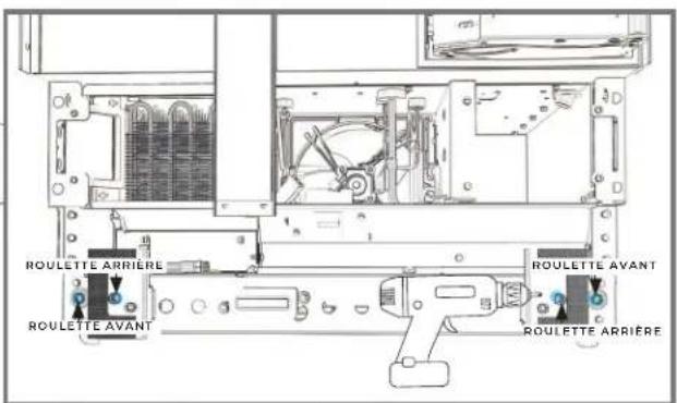
text_image
ROULETTE ARRIÈRE ROULETTE AVANT ROULETTE AVANT ROULETTE ARRIÈRE
8.2
DEUXIÈME APPAREIL : FIXER LA BRIDE DE POSITIONNEMENT.
natural_image
Line drawing of a mechanical device with a drill bit and control panel, no text or symbols present
8.3
PLACER SANS SERRER DES VIS DANS LA BRIDE D'INSTALLATION ET LA BRIDE BADASS DE SOFFITE.
natural_image
Technical line drawing of a mechanical assembly with a tool and component, shown from two different angles (no text or symbols present)8.4
TROISIÈME APPAREIL : ÉTEINDRE L'ALIMENTATION.
natural_image
Technical line drawing of a mechanical assembly with no visible text or symbolsAVANT DE BRANCHER L'APPAREIL, LIRE LES AVERTISSEMENTS.
AVERTISSEMENT
natural_image
Line drawing of an electrical outlet and a connected power plug (no text or symbols)AVANT DE DÉPLACER L'APPAREIL, LIRE TOUS LES AVERTISSEMENTS.
AVERTISSEMENT
natural_image
Architectural floor plan showing three rectangular chambers with side walls and a central horizontal structure, no text or symbols present.
8.8
TROISIÈME APPAREIL : PLACER À LA LIGNE DE 84 PO.
text_image
84 PO8.9
FIXER LE HAUT DU DEUXIÈME APPAREIL AU TROISIÈME APPAREIL.
natural_image
Technical line drawing of a mechanical assembly with no visible text or symbols8.12
TROISIÈME APPAREIL : RÉPÉTER POUR LA BRIDE DU BAS.
natural_image
Technical line drawing of a mechanical assembly with no visible text or symbols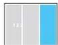
8.13
RACCORDER LE TUYAU D'ARRIVÉE D'EAU.
natural_image
Technical diagram of a mechanical assembly with blue tubing and component labels (no readable text or symbols)
PRÉPARATION
DE L'APPAREIL POUR SON UTILISATION
9.1
POUR CHAQUE APPAREIL : ALIGNER LE BOÎTIER DU FILTRE ENTRE LES BRIDES SITUÉS AU HAUT DE L'APPAREIL.
natural_image
Technical line drawing of a mechanical assembly with blue component placement (no text or symbols)9.2
POUR CHAQUE APPAREIL : INSTALLER DE NOUVEAU LE BOÎTIER EN POUSSANT AVEC FORCE VERS LA GAUCHE.
natural_image
Technical line drawing of a mechanical assembly with blue component and mounting holes (no text or symbols)9.3
POUR CHAQUE APPAREIL : INSÉRER LE FILTRE À EAU JUSQU'À CE QU'IL SOIT BIEN PLACÉ.
natural_image
Technical line drawing of a mechanical device with blue component and directional arrows (no text or symbols)9.4
POUR CHAQUE APPAREIL : FAIRE TOURNER LE FILTRE DANS LE SENS HORAIRE POUR ALIGNER LES FLÈCHES.

text_image
Technical diagram of a mechanical device with labeled components and directional arrows indicating motion or flow.9.5
POUR CHAQUE APPAREIL : FIXER À L'AIDE DE DEUX VIS ET REPLACER LE COUVERCLE.

text_image
Embout de perceuse de 5 mm
9.6
POUR CHAQUE APPAREIL : RÉINSTALLER LA GRILLE D'AÉRATION.
text_image
Technical diagram of a server rack with labeled components and blue panel areas, showing internal structure and connection points.
9.7
POUR CHAQUE APPAREIL : METTRE L'APPAREIL SOUS TENSION
natural_image
Technical line drawing of a mechanical assembly with no visible text or symbols
VÉRIFICATION DE L'INSTALLATION
P.201 PRÉPARATION DE LA PLINTHE EN BOIS PERSONNALISÉE
P.204 PRÉPARATION DE LA PLINTHE EN ACIER INOXYDABLE
P.207 ALIGNEMENT ET INSTALLATION DES PLINTHES
PRÉPARATION DE LA
PLINHE
EN BOIS PERSONNALISÉE
10.1
MESURER ET MARQUER LA LIGNE CENTRALE DE LA PLINTHE.
natural_image
Simple line drawing of a pencil and a vertical line on a rectangular base (no text or symbols)

EFFECTUER TOUTES LES ÉTAPES POUR CHAQUE APPAREIL.
10.2
GABARIT D'ALIGNEMENT
text_image
CUSTOM WOOD TOE KICK PANEL TEMPLATE GABARIT DE PANNEAU DE SEUIL DE PORTE EN BOIS SUR MESURE W13040865 AUXIN TO TUR OF 100 AND BASES AUXINAN ANES LE SOUI ET PANNEAU DE SOUIE DE PONTES AUXIN TO CENTRÈURE AUXINAN ANES LA CHINE CONTRAÎLE AUXIN TO CENTRÈURE AUXINAN ANES LA CHINE CONTRAÎLE
10.3
MARQUE L'EMPLACEMENT DES TAMPONS DE MAINTIEN.
text_image
CUSTOM WOOD TOE KICK PANEL TEMPLATE GABARIT DE PANNEAU DE SEUIL DE PORTE EN BOIS SUR MESURE W11048365 UNIT PART 12 LAMMAGE DE L'ARTS AUXO ET 100 OF 100 FOR ANES LABORATION LE AVE ET PUMBERATION DE BOUR DE POURT AUXO ET CONTROLLED A URBAN-POST ET LA VARE CONTROLLED UNIT PART 12 LAMMAGE DE L'ARTS AUXO ET CONTROLLED A URBAN-POST ET LA VARE CONTROLLED
10.5
FIXER LES TAMPONS DE MAINTIEN AUX POINTS.
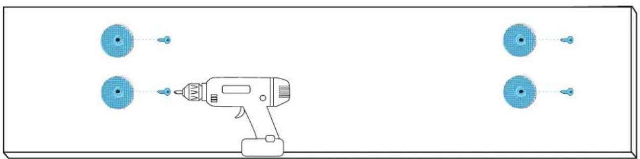
natural_image
Diagram of a handheld electric drill with four circular components and connecting wires (no text or symbols)
PRÉPARATION DE LA
PLINHE
EN ACIER INOXYDABLE
11.1
POUR CHAQUE APPAREIL : DÉVISSER ET JETER LE FAISCEAU DE CÂBLAGE WI-FI.
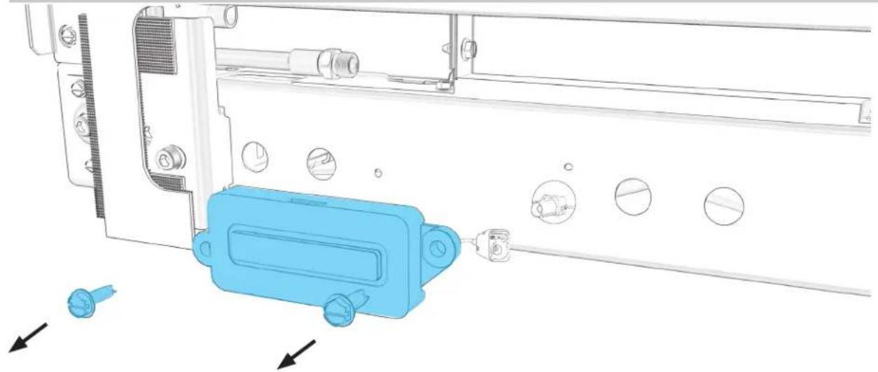
natural_image
Technical diagram of a mechanical assembly with blue plastic component and directional arrows indicating movement (no text or symbols)
11.2
DÉBRANCHER LE FIL WI-FI BLEU DU FAISCEAU DE CÂBLAGE.
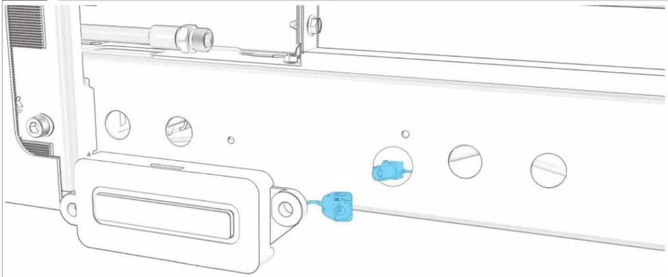
natural_image
Technical line drawing of a mechanical assembly with circular components and a blue connector (no text or symbols)
11.3
RELLIER LES FILS BLEUS DE LA PLINTHE ET DE L'APPAREIL.
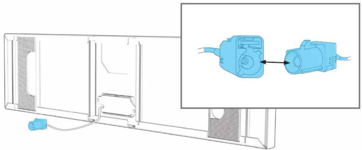
natural_image
Technical line drawing of a mechanical assembly with a blue connector and component, shown alongside an inset image of a blue electrical connector (no text or symbols present)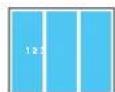
ALIGNEMENT ET INSTALLATION DE LA
PLINHE
12.1
ALIGNER LES BRIDES DE LA PLINTHE AVEC LA PLINTHE DU MEUBLE.
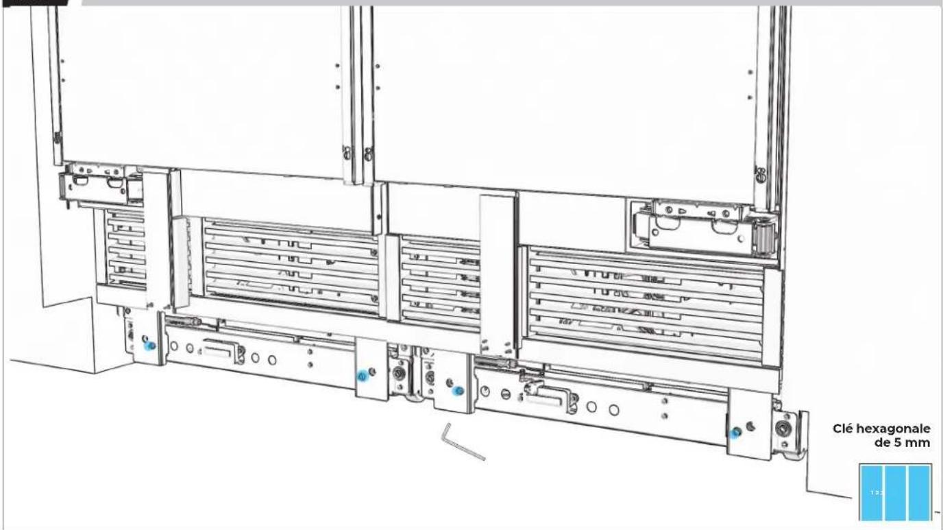
text_image
Clé hexagonale de 5 mm 13.212.2
VÉRIFIER QUE LES BRIDES SONT TOUTES ALIGNÉES.
natural_image
Technical line drawing of a server rack with multiple drive bays and indicator lights (no text or symbols)12.3
ALIGNER LES TAMPONS DE MAINTIEN DE LA PLINTHE AVEC LES BRIDES.

natural_image
Technical line drawing of a server rack with blue panel and inset view showing internal components (no text or symbols)12.4
PRESSER FERMEMENT POUR FIXER.

text_image
Technical diagram of a server rack system with labeled components and a blue panel inset showing internal structure.12.5
MESURER L'ÉCART. S'IL Y A UN ÉCART, ENLEVER LA PLINTHE.
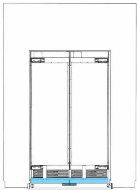
natural_image
Architectural cross-section diagram of a multi-level building or structure with structural elements (no text or labels)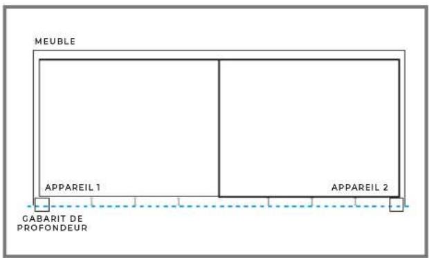
text_image
MEUBLE APPAREIL 1 APPAREIL 2 GABARIT DE PROFONDEUR
12.6
AJUSTER LES BRIDES POUR ALIGNER LA PLINTHE.
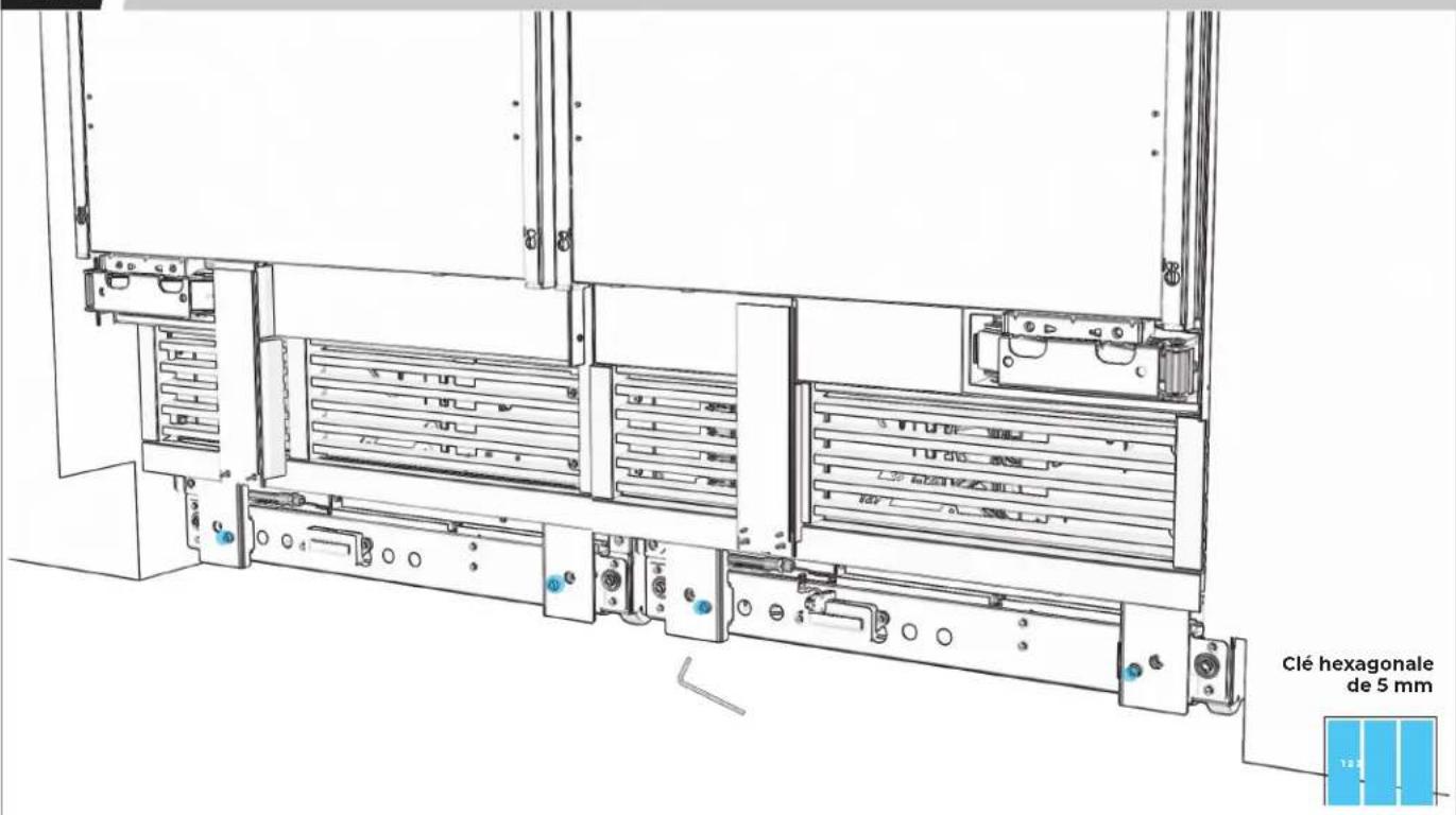
text_image
Clé hexagonale de 5 mm12.7
CONFIRMER L'ALIGNEMENT ET RÉALIGNER AU BESOIN.
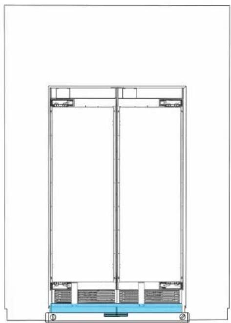
natural_image
Architectural cross-section diagram of a building facade with structural layers and water level (no text or symbols)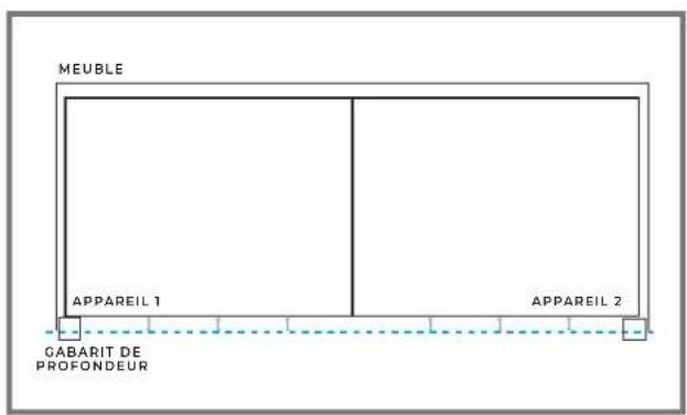
text_image
MEUBLE APPAREIL 1 APPAREIL 2 GABARIT DE PROFONDEUR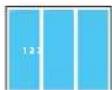
PRÉPARATION DU
PANNEAU
DE BOIS PERSONNALISÉ
13.1
RETIRER LE RUBAN POUR FAIRE SORTIR LA GARNITURE DE BRIDE.

natural_image
Line drawing of a refrigerator interior showing front and side views (no text or symbols)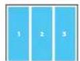

EFFECTUER TOUTES LES ÉTAPES POUR CHAQUE APPAREIL.
13.2
PLACER LE PANNEAU FACE VERS LE BAS.
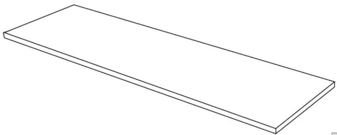
natural_image
Simple line drawing of a rectangular plate or shelf (no text or symbols)

PLACER SUR UNE SURFACE PLANE ET COUVERTE.
13.3
MESURER ET MARQUER LE CENTRE DU PANNEAU.
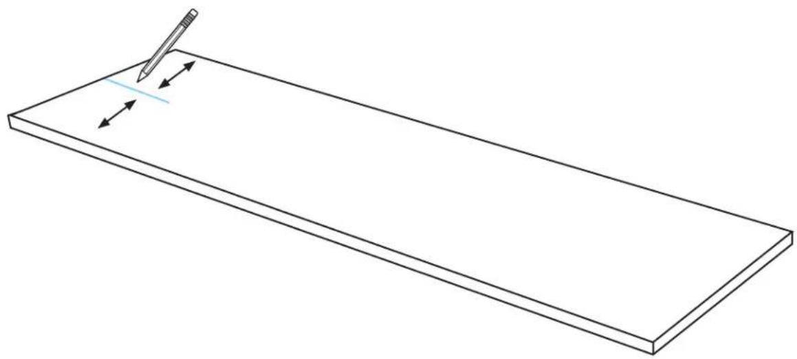
natural_image
Simple line drawing of a rectangular plate with a pencil and directional arrows indicating writing or editing (no text or symbols)
13.4
MARQUE LES TROUS GAUCHE ET DROIT.
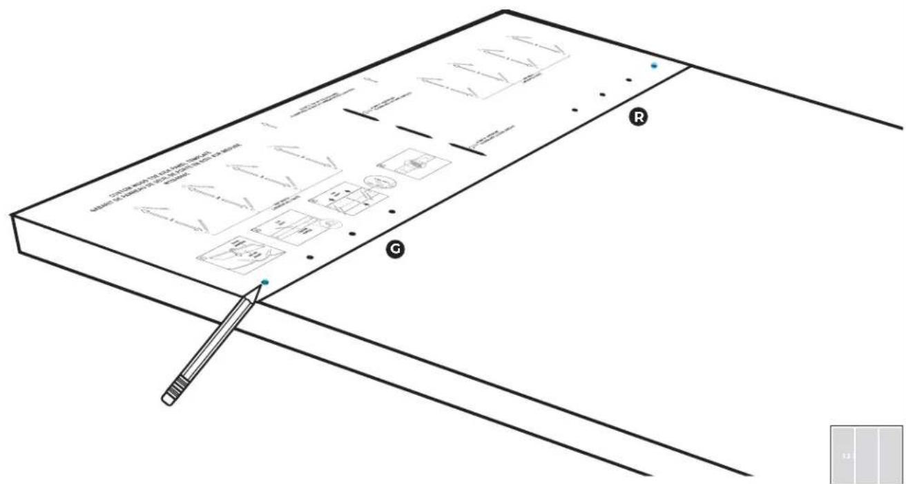
text_image
Technical diagram of a mechanical assembly with labeled components and annotations in Chinese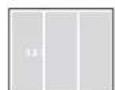
13.5
PERCER LES TROUS.
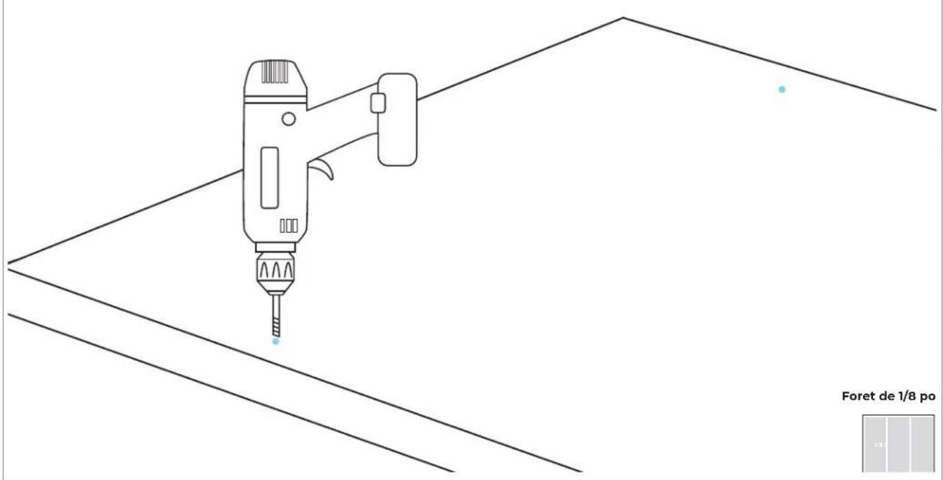
text_image
Foret de 1/8 po13.6
PLACER DES ATTACHES DANS LES TROUS PRÉPERCÉS.
text_image
Embout de perceuse carré no 2
13.7
S'ASSURER QU'IL Y A UN ESPACE DE 1/8 PO (3,2 MM).
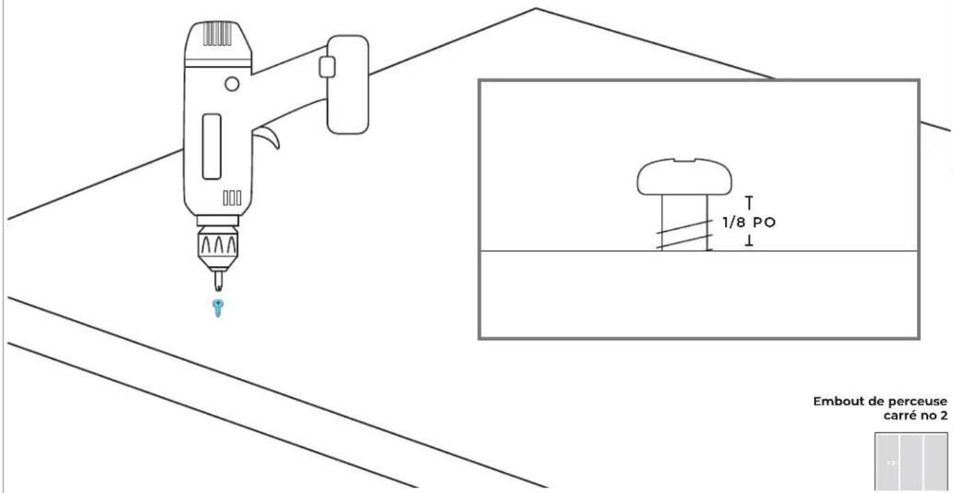
text_image
1/8 PO Embout de perceuse carré no 2PRÉPARATION DU
P ∧ N N E ∧
EN ACIER INOXYDABLE
14.1
RETIRER LE RUBAN POUR FAIRE SORTIR LA GARNITURE DE BRIDE.
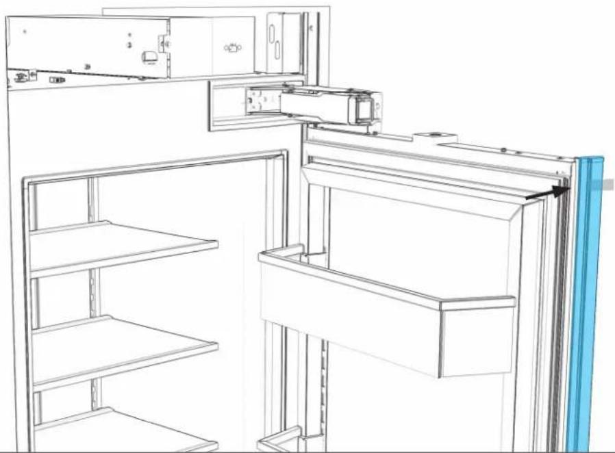
natural_image
Line drawing of a refrigerator interior showing front and rear shelves with doorways and shelf outlines (no text or symbols)

EFFECTUER TOUTES LES ÉTAPES POUR CHAQUE APPAREIL.
14.2
PLACER LE PANNEAU FACE VERS LE BAS.
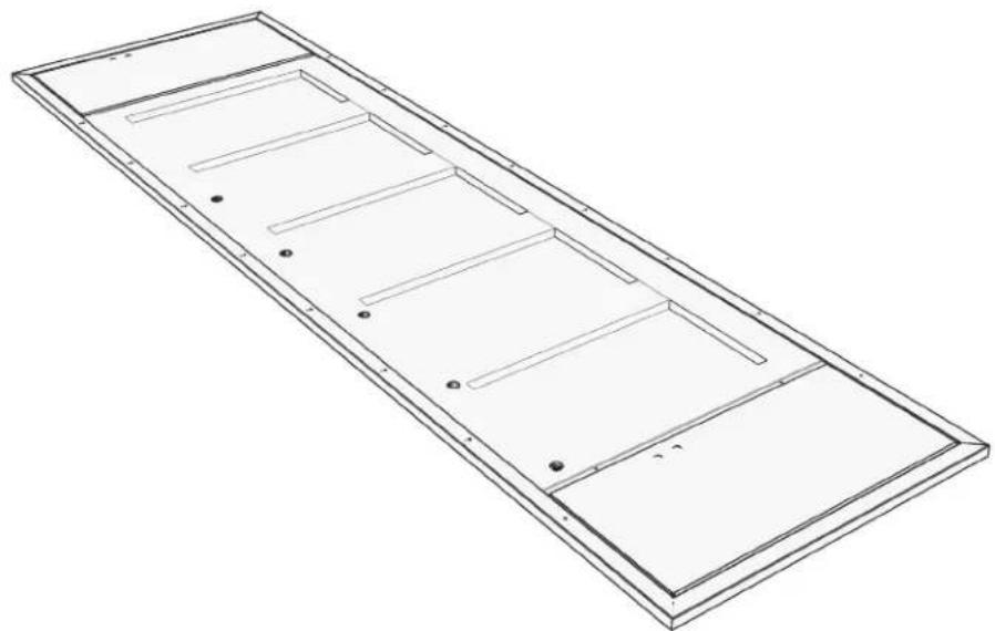
natural_image
Isometric line drawing of a rectangular metal frame with internal compartments and mounting holes (no text or symbols)

PLACER SUR UNE SURFACE PLANE ET COUVERTE
14.3
PLACER DES ATTACHES DANS LES TROUS PRÉPERCÉS.
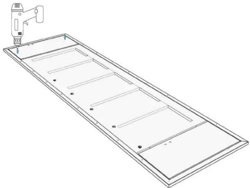
natural_image
Technical line drawing of a rectangular panel with internal compartments and a tool in the top-right corner (no text or symbols)Embout de perceuse carré no 2
14.4
S'ASSURER QU'IL Y A UN ESPACE DE 1/8 PO (3,2 MM).
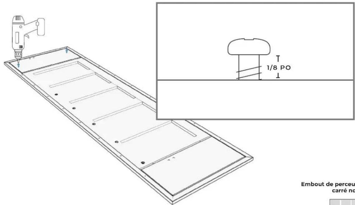
text_image
1/8 PO Embout de perceu carré noEmbout de perceuse carré no 2

SUSPENSION ET ALIGNEMENT DU
PANNEAU
15.1
POUR CHAQUE APPAREIL : PLACER LES ATTACHES DANS LES FENTES DU HAUT DES GARNITURES D'AJUSTEMENT DE PORTE.
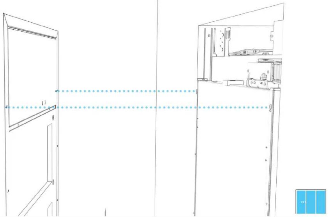
natural_image
Architectural line drawing of a double door and cabinet with labeled components (no text or symbols)15.2
POUR CHAQUE APPAREIL : AJUSTER MANUELLEMENT LA POSITION DU PANNEAU DE PORTE.

natural_image
Architectural floor plan showing a double door with a central vertical beam and horizontal supports (no text or labels)
natural_image
Line drawing of a mechanical device with a blue component, no text or symbols present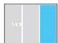
15.3
POUR CHAQUE APPAREIL : SERRER LES DEUX ATTACHES SUPÉRIEURES.
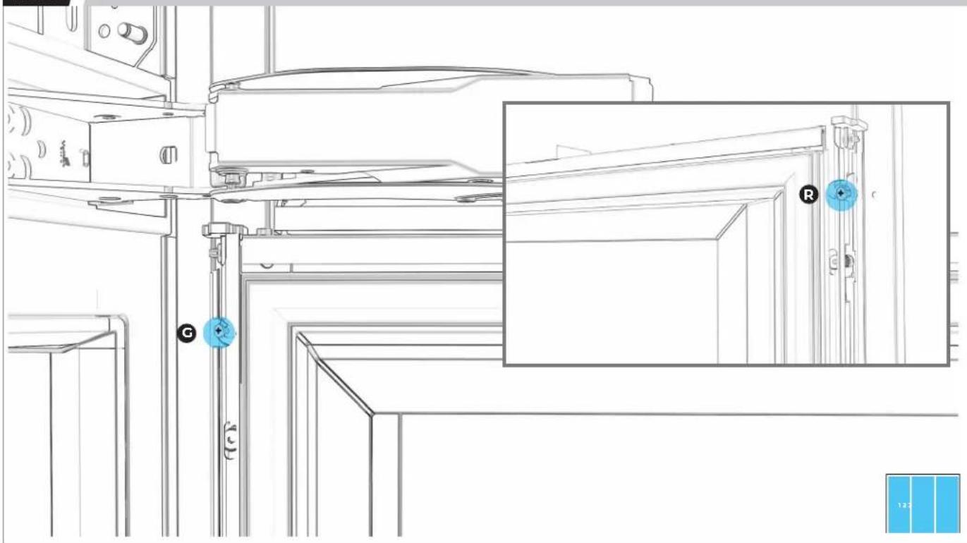
natural_image
Technical line drawing of a mechanical assembly with labeled components (G, R) and a blue inset view showing a close-up of a door mechanism (no text or symbols beyond labels)15.4
POUR CHAQUE APPAREIL : PLACER SANS SERRER DEUX ATTACHES DU BAS.

natural_image
Technical line drawing of a cabinet or enclosure with internal components and blue measurement indicators (no text or symbols)15.5
POUR CHAQUE APPAREIL : DESSERRER SIX VIS D'AJUSTEMENT PAR CÔTÉ.
text_image
Technical diagram of a refrigerator with numbered labels pointing to different compartments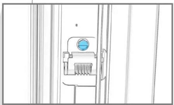
natural_image
Line drawing of a mechanical device with a blue circular component and textured base (no text or symbols)

UTILISER UN ADAPTATEUR À ANGLE DROIT POUR PLUS DE FACILITÉ.
15.6
POUR CHAQUE APPAREIL : AJUSTER LA HAUTEUR DU PANNEAU DE PORTE.
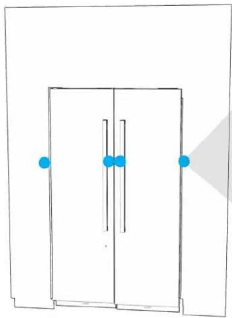
natural_image
Simple line drawing of a door with blue dots and a shaded triangular area (no text or symbols)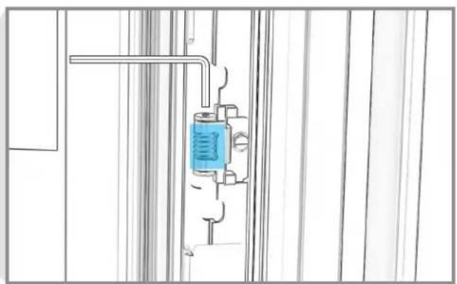
natural_image
Pure technical line drawing of a mechanical assembly with no text, numbers, or symbolsnatural_image
Pure architectural line drawing of a door frame with blue markers and a gray shadow (no text or symbols)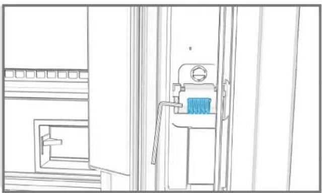
natural_image
Line drawing of a mechanical device with a blue component, no text or symbols presentnatural_image
Architectural floor plan showing two rectangular structures with horizontal beams and internal compartments (no text or labels)
15.9
POUR CHAQUE APPAREIL : PLACER ET SERRER LES 16 ATTACHES.
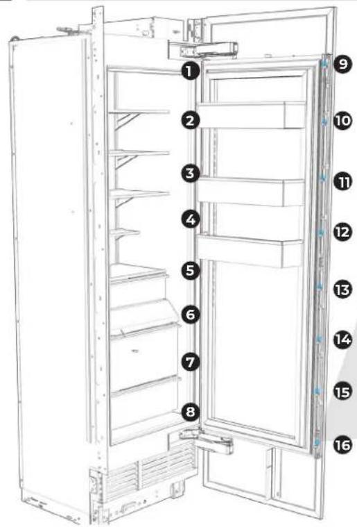
text_image
Diagram of an open refrigerator with numbered labels pointing to different compartments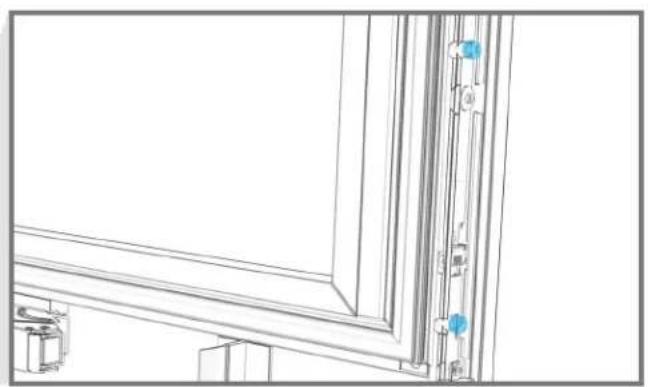
natural_image
Architectural line drawing of a window frame with vertical door and wall-mounted fixtures (no text or symbols)
15.10
POUR CHAQUE APPAREIL : SERRER LE PANNEAU DE PORTE.
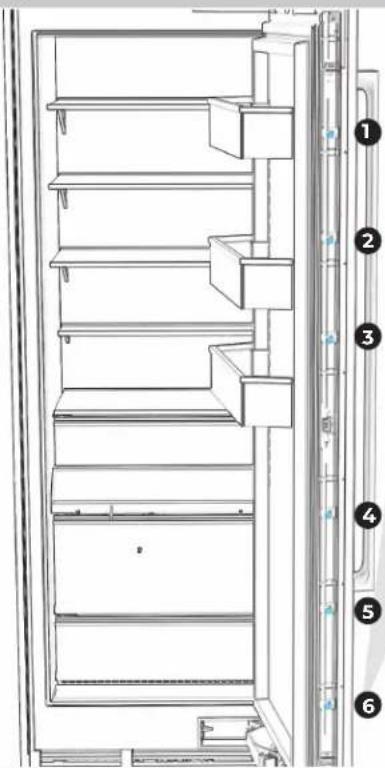
text_image
Technical diagram of a refrigerator with numbered parts for identification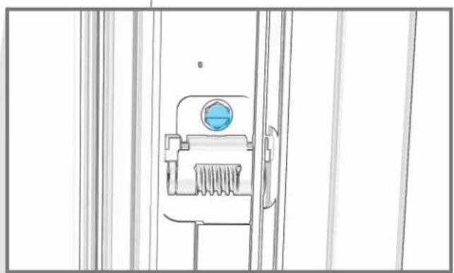
natural_image
Technical line drawing of a mechanical component with a blue circular feature on the left side (no text or symbols)
15.11
POUR CHAQUE APPAREIL : RÉINSTALLER LES GARNITURES DE BRIDE.

natural_image
Line drawing of a refrigerator interior with blue panel and directional arrows indicating rotation (no text or symbols)T E R M I N E R
L'INSTALLATION
16.1
POUR CHAQUE APPAREIL : SERRER LES VIS POUR BIEN FIXER LES GARNITURES DE CÔTÉ DE CHAQUE CÔTÉ.
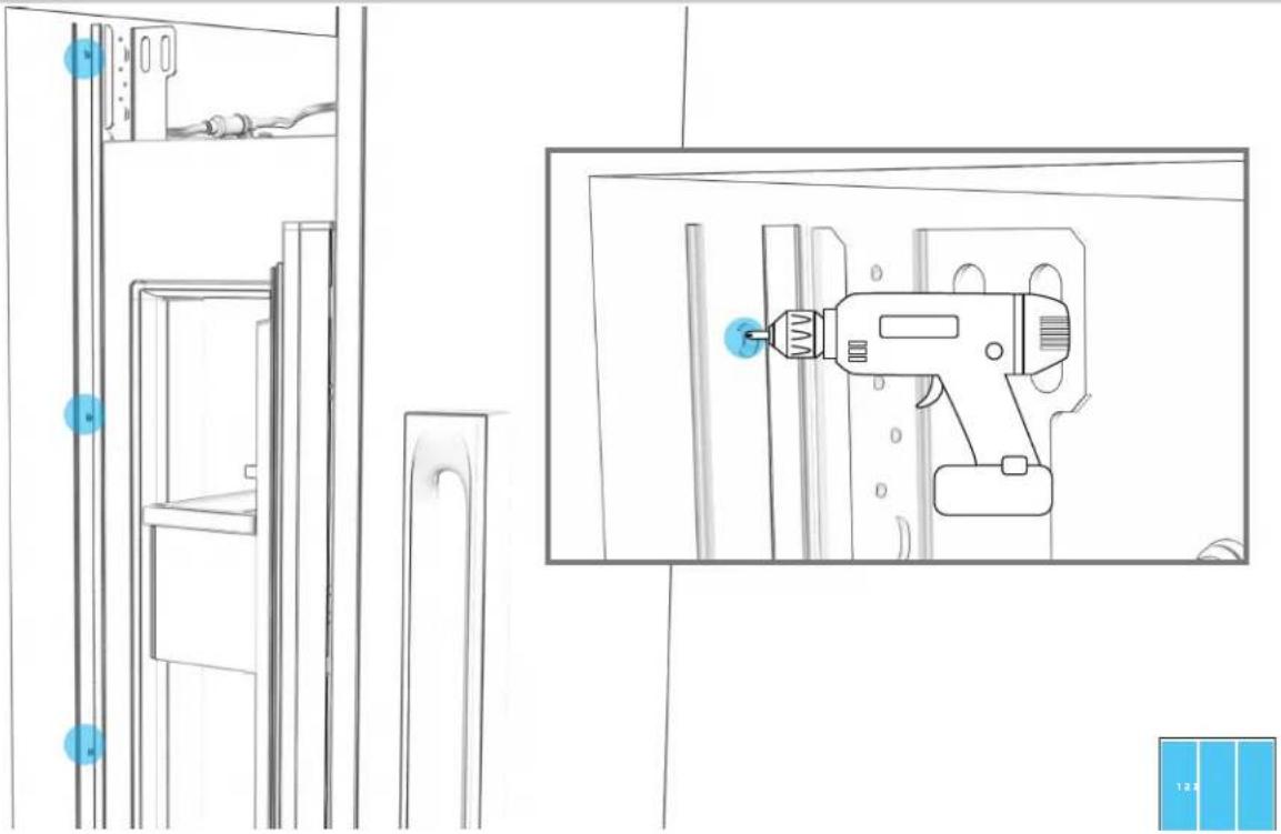
natural_image
Line drawing of a refrigerator interior with a hand tool inserted into the door (no text or symbols)16.2
POUR CHAQUE APPAREIL : FIXER LES SÉPARATEURS D'AIR AUX PANNEAUX DE PORTE.
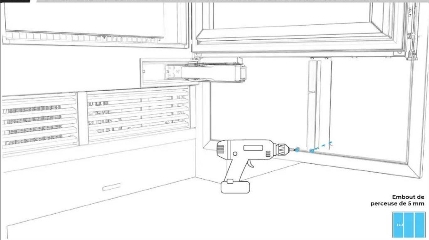
text_image
Embout de perceuse de 5 mm 12316.3
POUR CHAQUE APPAREIL : RETIRER LA PELLICULE.
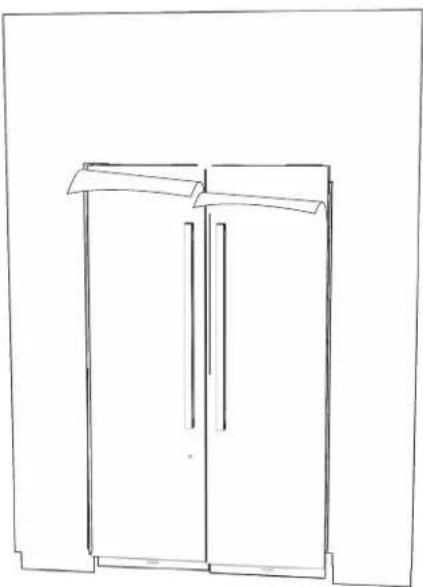
natural_image
Line drawing of a two-decker cabinet or wardrobe unit (no text or symbols)
LIRE LES AVERTISSEMENTS AVANT LES DERNIÈRES VÉRIFICATIONS.
AVERTISSEMENT

®/TM ©2019 JennAir. All rights reserved.
Printed in the U.S.A.
Imprimé aux É.-U.