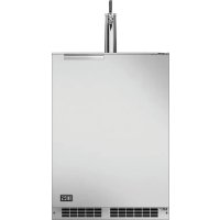
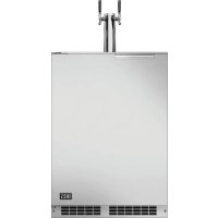
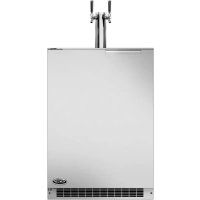
RF24TL2 - Beer dispenser DCS - Free user manual and instructions
Find the device manual for free RF24TL2 DCS in PDF.
| Product Type | Outdoor Beer Dispenser / Beer Kegerator |
| Brand | DCS |
| Model | RF24TL2 |
| Dimensions (H x W x D) | 33 3/4 to 34 3/4 in H x 24 1/4 in W x 26 1/4 in D |
| Weight | 63.6 kg (140 lb) |
| Power Supply | 115 V / 60 Hz / 15 A, dedicated grounded circuit |
| Temperature Range | 1 to 8°C (34 to 46°F) |
| Recommended Ambient Temperature | 13 to 46°C (55 to 115°F) |
| Keg Capacity | 1/6, 1/4 or 1/2 barrel; up to 2 kegs with double column |
| CO2 Tank | 5 lb (2.27 kg), adjustable pressure 12-14 psi (lager) or 9-12 psi (ale) |
| Material | Stainless steel |
| Key Functions | Temperature adjustment, alarms (door open, sensor, high/low temperature), mute |
| Included Accessories | Stainless steel column, keg coupler(s), CO2 regulator, 5 lb CO2 tank, hose clamps, faucet wrench |
| Installation | Under counter or on counter; anti-tip bracket required; free front clearance, 1 in (2.5 cm) rear clearance |
| Cleaning and Maintenance | Disassemble faucet and coupler; clean lines; dust front grille regularly |
| Warranty | 2 years parts and labor; 5 years on sealed refrigeration system |
| Repairability | Accessible parts; DCS customer service at 1-888-936-7872 |
| General Information | Designed for outdoor residential use; avoid abrasive cleaners; winterization recommended below 3.3°C |
Frequently Asked Questions - RF24TL2 DCS
User questions about RF24TL2 DCS
0 question about this device. Answer the ones you know or ask your own.
Ask a new question about this device
Download the instructions for your Beer dispenser in PDF format for free! Find your manual RF24TL2 - DCS and take your electronic device back in hand. On this page are published all the documents necessary for the use of your device. RF24TL2 by DCS.
USER MANUAL RF24TL2 DCS
text_image
DCS by Fisher&PaykelOUTDOOR BEER DISPENSERS
Installation, Operation and Maintenance Instructions
natural_image
Close-up of a metallic door panel corner with a curved metal clip, mounted on a stone wall (no text or symbols visible)MODELS:
MODÈLES :
RF24TR1
RF24TL1
RF24BTR1
RF24BTL1
Contents:
Safety information 2
Unpacking your appliance ....3
Warranty registration....3
Installing your appliance ....4
Cabinet clearances ....4
Leveling the appliance ....4
Electrical connection 5
Installing the anti-tip device ....6
Product dimensions ....8
UsingyourElectroniccontrol....9
Startingyourappliance....9
Turning your appliance "ON" or "OFF"......9
Adjusting the temperature....9
Beer dispenser operation....9
Alarms....9
Door ajar....9
Temperature sensor fault....9
High and Low temperature alarms....9
Alarm mute....9
Using your beer dispenser....10
Tap equipment and assembly....10
CO_2 regulator....14
Drain kit....15
Care and cleaning 15
Cleaning the drain sump....15
Keg coupler cleaning....16
Faucet cleaning 16
Front grille 16
Cabinet....16
Interior....16
Long term storage / winterization 17
Stainless steel maintenance 19
Energy saving tips 20
Troubleshooting....21
Obtaining service 21
Warranty 22
Important Safety Instructions
Warnings and safety instructions appearing in this guide are not meant to cover all possible conditions and situations that may occur. Common sense, caution, and care must be exercised when installing, maintaining, or operating this appliance.
Recognize Safety Symbols, Words, and Labels.

WARNING
WARNING - You can be killed or seriously injured if you do not follow these instructions.

CAUTION
CAUTION-Hazards or unsafe practices which could result in personal injury or property / product damage.
NOTE
NOTE-Important information to help assure a problem free installation and operation.
State of California Proposition 65 Warnings:
WARNING: This product contains one or more chemicals known to the State of California to cause cancer.
WARNING: This product contains one or more chemicals known to the State of California to cause birth defects or other reproductive harm.

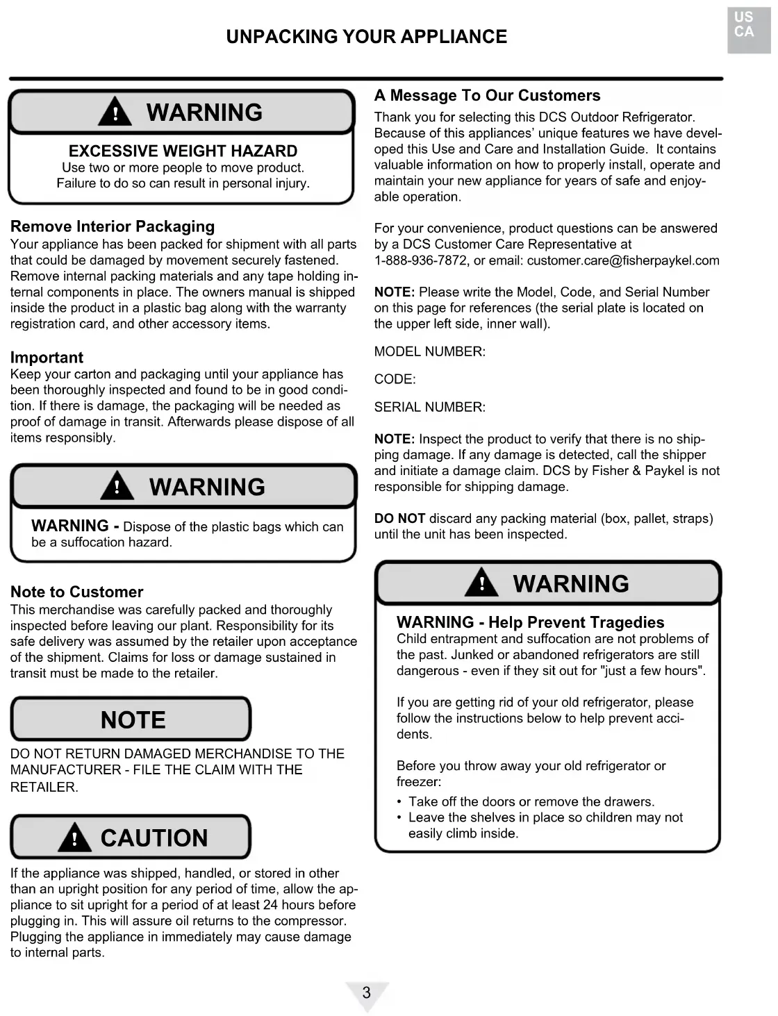
WARNING
EXCESSIVE WEIGHT HAZARD
Use two or more people to move product.
Failure to do so can result in personal injury.
Remove Interior Packaging
Your appliance has been packed for shipment with all parts that could be damaged by movement securely fastened.
Remove internal packing materials and any tape holding internal components in place. The owners manual is shipped inside the product in a plastic bag along with the warranty registration card, and other accessory items.
Important
Keep your carton and packaging until your appliance has been thoroughly inspected and found to be in good condition. If there is damage, the packaging will be needed as proof of damage in transit. Afterwards please dispose of all items responsibly.

WARNING
WARNING - Dispose of the plastic bags which can be a suffocation hazard.
Note to Customer
This merchandise was carefully packed and thoroughly inspected before leaving our plant. Responsibility for its safe delivery was assumed by the retailer upon acceptance of the shipment. Claims for loss or damage sustained in transit must be made to the retailer.
NOTE
DO NOT RETURN DAMAGED MERCHANDISE TO THE MANUFACTURER - FILE THE CLAIM WITH THE RETAILER.

CAUTION
If the appliance was shipped, handled, or stored in other than an upright position for any period of time, allow the appliance to sit upright for a period of at least 24 hours before plugging in. This will assure oil returns to the compressor. Plugging the appliance in immediately may cause damage to internal parts.
A Message To Our Customers
Thank you for selecting this DCS Outdoor Refrigerator. Because of this appliances' unique features we have developed this Use and Care and Installation Guide. It contains valuable information on how to properly install, operate and maintain your new appliance for years of safe and enjoyable operation.
For your convenience, product questions can be answered by a DCS Customer Care Representative at 1-888-936-7872, or email: customer.care@fisherpaykel.com
NOTE: Please write the Model, Code, and Serial Number on this page for references (the serial plate is located on the upper left side, inner wall).
MODEL NUMBER:
CODE:
SERIAL NUMBER:
NOTE: Inspect the product to verify that there is no shipping damage. If any damage is detected, call the shipper and initiate a damage claim. DCS by Fisher & Paykel is not responsible for shipping damage.
DO NOT discard any packing material (box, pallet, straps) until the unit has been inspected.

WARNING
WARNING - Help Prevent Tragedies
Child entrapment and suffocation are not problems of the past. Junked or abandoned refrigerators are still dangerous - even if they sit out for "just a few hours".
If you are getting rid of your old refrigerator, please follow the instructions below to help prevent accidents.
Before you throw away your old refrigerator or freezer:
• Take off the doors or remove the drawers.
- Leave the shelves in place so children may not easily climb inside.
Select Location
The proper location will ensure peak performance of your appliance. We recommend a location where the unit will be out of direct sunlight and away from heat sources. To ensure your product performs to specifications, the recommended installation location temperature range is from 55 to 115°F (13 to 46°C).
Cabinet Clearance
Ventilation is required from the bottom front of the appliance. Keep this area open and clear of any obstructions. Adjacent cabinets and counter top can be installed around the appliance as long as the front grille remains unobstructed.

CAUTION
Front Grille
Do not obstruct the front grille. The openings within the front grille allow air to flow through the condenser heat exchanger. Restrictions to this air flow will result in increased energy usage and loss of cooling capacity. For this reason it is important this area not be obstructed and the grille openings kept clean (See Figure 1). The use of a custom made grille is not recommended as it may restrict air flow.
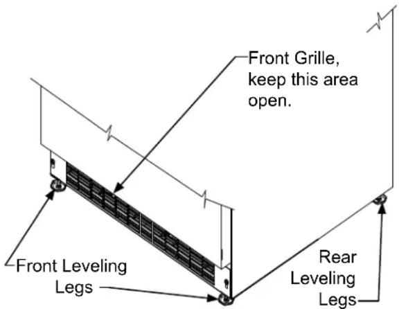
text_image
Front Grille, keep this area open. Front Leveling Legs Rear Leveling LegsFigure 1
Leveling Legs
Adjustable legs at the front and rear corners of the appliance should be set so the unit is firmly positioned on the floor and level from side to side and front to back. The overall height of your appliance may be adjusted between the minimum, 33 ^3/4 " (85.7 cm), by turning the leveling leg in (CW ∼) and the maximum, 34 ^3/4 " (88.3 cm) by turning the leveling leg out (CCW ∼).
To adjust the leveling legs, place the appliance on a solid surface and protect the floor beneath the legs to avoid scratching the floor. With the assistance of another person, lean the appliance back to access the front leveling legs. Raise or lower the legs to the required dimension by turning the legs. Repeat this process for the rear by tilting the appliance forward using caution. On a level surface check the appliance for levelness and adjust accordingly.
The front grille screws may be loosened and the grille adjusted to the desired height. When adjustment is complete tighten the two front grille screws. (See Figure 2).
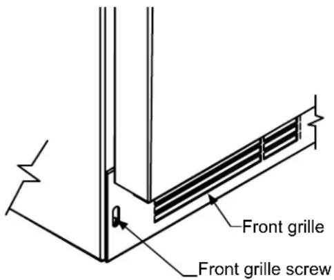
text_image
Front grille Front grille screwFigure 2
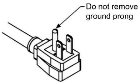
text_image
Do not remove ground prongFigure 3
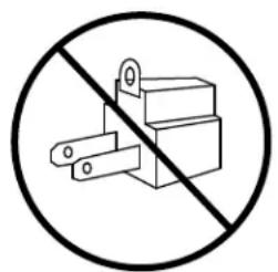
natural_image
Prohibition sign showing a crossed-out electrical component (no text or symbols)Figure 4
natural_image
Simple line drawing of an electrical plug and two socket covers (no text or symbols)Figure 5

WARNING
Electrical Shock Hazard
- Do not use an extension cord with this appliance. They can be hazardous and can degrade product performance.
- This appliance should not, under any circumstances, be installed to an un-grounded electrical supply.
- Do not remove the grounding prong from the power cord. (See Figure 3).
- Do not use an adapter. (See Figure 4).
- Do not splash or spray water from a hose on the appliance. Doing so may cause an electrical shock, which may result in severe injury or death.
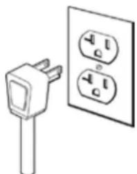
Electrical Connection
A grounded 115 volt, 15 amp dedicated circuit is required.
This product is factory equipped with a power supply cord that has a three-pronged, grounded plug. It must be plugged into a mating grounding type receptacle in accordance with the National Electrical Code and applicable local codes and ordinances (see Figure 5). If the circuit does not have a grounding type receptacle, it is the responsibility and obligation of the customer to provide the proper power supply. The third ground prong should not, under any circumstances, be cut or removed.
NOTE
Ground Fault Circuit Interrupters (GFCI) are prone to nuisance tripping which will cause the appliance to shut down. GFCI's are generally not used on circuits with power equipment that must run unattended for long periods of time, unless required to meet local building codes and ordinances.

WARNING
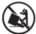
• ALL APPLIANCES CAN TIP RESULTING IN INJURY.
• INSTALL THE ANTI-TIP BRACKET PACKED WITH THE APPLIANCE.
• FOLLOW THE INSTRUCTIONS BELOW
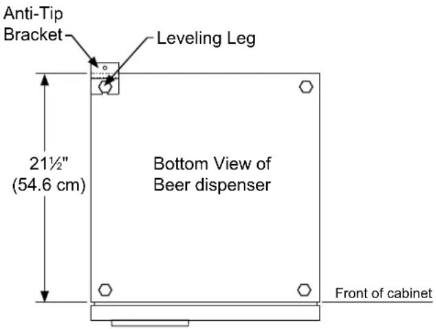
text_image
Anti-Tip Bracket Leveling Leg 21½" (54.6 cm) Bottom View of Beer dispenser Front of cabinetFigure 6
Anti-Tip Device

WARNING
If your refrigerator is not located under a counter top (free standing), you must use an anti-tip device installed as per these instructions. If the refrigerator is removed from its location for any reason, make sure that the device is properly engaged with the anti-tip bracket when you push the refrigerator back into the original location. If the device is not properly engaged, there is a risk of the refrigerator tipping over, with the potential for property damage or personal injury.
NOTE
If installing on a concrete floor, concrete fasteners are required, (not included with the anti-tip kit).

CAUTION
Any finished flooring should be protected with appropriate material to avoid damage when moving the unit.
Floor Mount Installation
The anti-tip bracket is to be located on the floor in the left or right rear corner of the beer dispenser as shown in Figure 6.
Step by step instructions for locating the position of the bracket:
1) Decide where you want to place the beer dispenser. Slide it into place, being careful not to damage the floor, leaving 1" (2.5 cm) of clearance from the rear wall to allow room for the anti-tip bracket.
2) Raise the rear leveling legs approximately 14 " (6 mm) to allow engagement with the anti-tip bracket. Level the unit by adjusting all the leveling legs as required. Turning the leveling leg counterclockwise will raise the unit and clockwise will lower the unit.
3) Make sure the beer dispenser is in the desired location, then mark on the floor the rear and side corner of the cabinet where the anti-tip bracket will be installed. If the installation does not allow marking the rear corner of the cabinet, then make temporary lines on the floor marking the front corner of the cabinet, excluding the door. Slide the beer dispenser out of the way. From the temporary line extend the sidewall line back 21½" (54.6 cm) as shown in Figure 6.
4) Align the anti-tip bracket to the marks on the floor so the side of the bracket lines up with the side of the cabinet mark, and the "V" notches on the anti-tip bracket line up with the end of the 21½" (54.6 cm) line (Rear of cabinet line).
5) Fasten the anti-tip bracket to the floor using the supplied screw. (See Figure 7).
6) Slide the cabinet back into position, making sure the rear cabinet leveling leg slides under the anti-tip bracket engaging the slot.
INSTALLING THE ANTI TIP DEVICE FOR FREESTANDING INSTALLATIONS
NOTE
When the floor mounted anti-tip bracket is used the minimum adjusted height of the cabinet is increased by 38 " (9 mm).
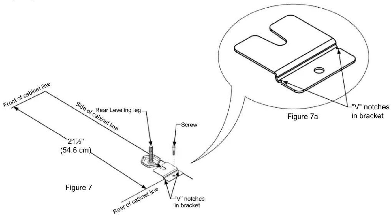
text_image
Front of cabinet line Side of cabinet line 21½" (54.6 cm) Figure 7 Rear Leveling leg Screw V" notches in bracket Figure 7a "V" notches in bracket| ROUGH-IN OPENING DIMENSIONS CABINET DIMENSIONS | |||||||||
| MODEL | "A" | "B" | "C" | "D" | "E" | "F" | "G" | "H" | "J" |
| All Models | 24 14 " (61.6 cm)24 12 " (62 cm)(with optional DCSSide trim kit) | **34" to 35"(86.4 to 88.9 cm) | * | 23 78 "(60.7 cm) | 33 34 " to 34 34 "(85.7 to 88.3 cm) | 23 ^23/_32 "(60.2 cm) | 26 14 "(66.7 cm) | 46 ^13/_32 "(117.9 cm) | 26 14 "(66.7 cm) |
| PRODUCT DATA | ||
| MODEL | ELECTRICAL REQUIREMENTS*** | PRODUCT WEIGHT |
| All Models 115 | V/60Hz/15A | 140 lbs(63.6 kg) |
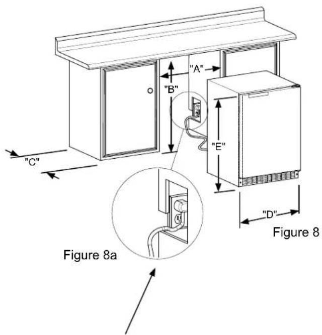
text_image
"A" "B" "E" "C" Figure 8a "D" Figure 8If necessary to gain clearance inside the rough-in opening a hole can be cut through the adjacent cabinet and the power cord routed through this hole to a power outlet. Another way to increase the available opening depth is to recess the power outlet into the rear wall to gain the thickness of the power cord plug.
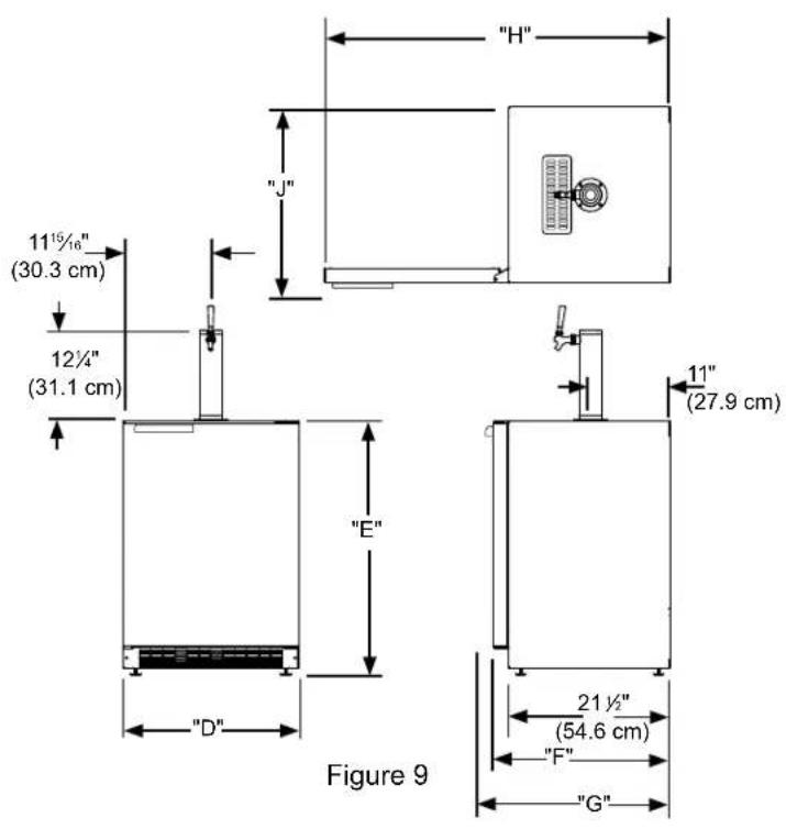
text_image
"H" "J" 11½/16" (30.3 cm) 12¼" (31.1 cm) "E" 11" (27.9 cm) "D" 21½" (54.6 cm) "F" "G" Figure 9* Depth dimension of rough-in opening may vary depending on each individual installation. To recess entire door "F" dimension plus 1" (2.5 cm) for thickness of power cord plug is required.
** Minimum rough-in opening required is to be larger than the adjusted height of the cabinet.
*** A grounded 15 amp dedicated circuit is required. Follow all local building codes when installing electrical and appliance.
Figure 10
close-up of control
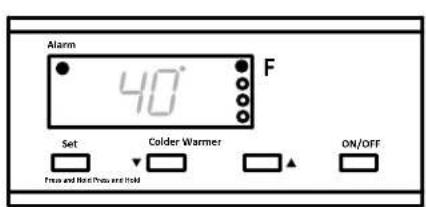
text_image
Alarm 40° F Set Colder Warmer Free and Hot (Yes or Hold) ON/OFFStarting your beer dispenser
Plug the beer dispenser power cord into a wall outlet. Your beer dispenser will begin cooling after power is applied.
If your beer dispenser does not start, check that the beer dispenser is turned on and the set temperature is cold enough.
Turning your beer dispenser ON or OFF
If the beer dispenser is on, the beer dispenser temperature will be shown on the display. To turn the beer dispenser off, press and hold the "ON/OFF" button for three seconds. "OFF" will appear on the display.
If the beer dispenser is not on, "OFF" will be shown on the display. To turn the beer dispenser on, press and hold the "ON/OFF" button for three seconds. The beer dispenser temperature will be shown on the display.
Set temperature
To set the beer dispenser temperature, press and hold the "SET" button. When the "SET" button is pressed, the display will show the set temperature. While holding the "SET" button, press the "WARMER" or "COLDER" buttons to adjust set temperature.
Beer dispenser operation
The available temperature range of the beer dispenser is 34 to 46°F (1 to 8°C).
It may take up to 24 hours for your beer dispenser to reach desired temperature. This will depend on amount of content loaded and number of door opening and closings.
For best results allow beer dispenser to "pull down" to desired set temperature before loading. Once contents are loaded, allow at least 48 hours for temperature to stabilize before making any adjustments to the set temperature.
Alarms
Your digital display function will monitor beer dispenser function and alert you with a series of audible and visual alarms.

- Door Ajar Alarm: If the door has been left open for over five minutes, the alarm will sound in one second intervals. The display
panel will flash "do" and the Alarm LED located at the top left of the display below the word "Alarm" will be illuminated. This will stop as soon as the door is closed.
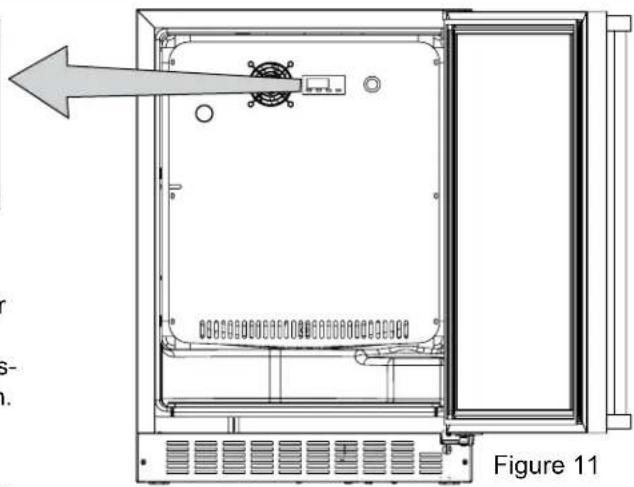
natural_image
Technical line drawing of an open electrical enclosure with a directional arrow indicating left motion (no text or symbols present)
• Temperature Sensor Fault: If the controller detects that the temperature sensor is not properly functioning, a temperature sensor
alarm will sound in one (1) second intervals. "E1" will flash on the display panel and the Alarm LED located at the top left of the display below the word "Alarm" will be illuminated.

- High and Low Temperature Alarm: If your unit reaches an unacceptable temperature outside of your set-point, the alarm will sound in (1) second intervals. The display panel will flash either "Hi" or "Lo" depending upon the condition and the Alarm LED light at the top
left of the display below the word "Alarm" will be illuminated. These alarms indicate that the compartment temperature has moved 10^ or more from the set point for more than 1 hour duration. The alarm will remain active until the condition is corrected.
NOTE
During initial appliance start-up, the high temperature alarm may sound until the interior temperature reaches set point. The high temperature alarm can also occur if the door remains open during an extended period of time (i.e. cleaning or door ajar alarm condition), high usage or loading with warm product. After a high temperature alarm condition check all perishables to ensure they are safe for consumption.
Alarm Mute
Press any key to mute the audible portion of an alarm.
NOTE
This action will only mute the alarm. If the condition that caused the alarm continues, the alarm code will continue to flash and will sound for 20 seconds every 60 minutes.
This beer dispensing unit will support 12 barrel or 14 barrel. The double draft tower units can support two sixth ( 16 ) barrels of beer. See chart below for quantity of beer in each barrel size.
| Barrel Sizes | |||
| 1/6 barrel 1/4 | Barrel 1/2 B | arrel | |
| Height | 23516" (59.2 cm) | 14^13/_16" (37.6 cm) | 23516" (59.2 cm) |
| Diameter | 914" (23.5 cm) | 17"(43.2 cm) | 17" to 1714" (43.2 to 43 cm) |
| Gallons 5.1 | 6 7.75 15.5 | ||
| #12 ounce Glasses | 60 82 163 | ||
Table A
| Keg Size | #of kegs per 5 pound CO2Tank |
| 5 gallon Corny 15 to 22 | |
| 1/6 barrel 14 to 21 | |
| 1/4 Barrel 10 to 14 | |
| 1/2 Barrel 5 to 7 | |
Table B
Tap Equipment and Assembly
Your dispensing kit includes the following parts:
Polished stainless steel tower with clear beer line (single or double dispense)
Tower Gasket
Phillips oval head screws
Knob for Tower (Faucet Handle)
Keg coupler(s)
CO2 regulator with red gas line(s) attached
Empty 5 pound CO₂ tank
Plastic clamp(s) large and small
Faucet wrench
Tools required for installation:
Flat bladed screwdriver
Phillips screwdriver
Pliers
Adjustable wrench or a 1 ^1/8 " open end wrench
12 " open end wrench

WARNING
CO _2 can be dangerous. If it becomes difficult to breathe and/or your head starts to ache, a high concentration of carbon dioxide may be present. Leave the area immediately.
- The CO_2 tank must always be connected to the regulator. Never connect the tank to the keg.
- The CO_2 tank must be securely mounted in the upright position. Secure it with the chain provided.
- Never drop or throw the CO_2 tank.
- Keep the CO_2 tank away from heat.
-
Ventilate the area after a CO_2 leak.
-
Remove shelving and packaged components from the interior of the refrigerator before beginning the assembly process.
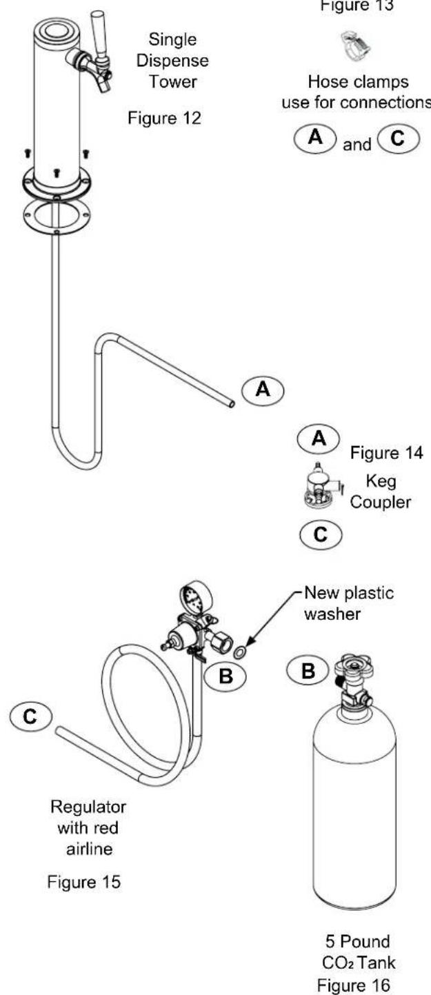
- Take your empty 5 pound CO₂ tank to your local gas supply dealer to be filled. You can usually find them in your "yellow pages" under "Welding Supply" or "Fire Protection". One 5 pound tank can process many kegs (see table "B") Your dealer should supply you with a new plastic washer every time the tank is filled. This washer is used at the regulator to tank connection. See Figure 15 and 22 on page 11. Replace the old washer with the new one whenever the tank is refilled.
- Tower mounting (if you are installing the unit under a counter skip to step 4). If you are mounting the tower directly to the top of the refrigerator, first remove the four screws from the top of the refrigerator. Remove the foam plug from the large hole in the top of the refrigerator. Feed the clear beer line through the tower gasket and the large hole in the refrigerator top. Align the 4 holes in the tower with the 4 holes in the refrigerator top and secure the tower with the 4 screws removed previously. Skip to step 5.
Single Dispense Tower Kit
Connect Ⓐ to Ⓐ ,etc......
text_image
Single Dispense Tower Figure 12 Figure 13 Hose clamps use for connections A and C Figure 14 Keg Coupler C New plastic washer B Regulator with red airline Figure 15 5 Pound CO₂ Tank Figure 16Double Dispense Tower Kit
Connect Ⓐ to Ⓐ ,etc......
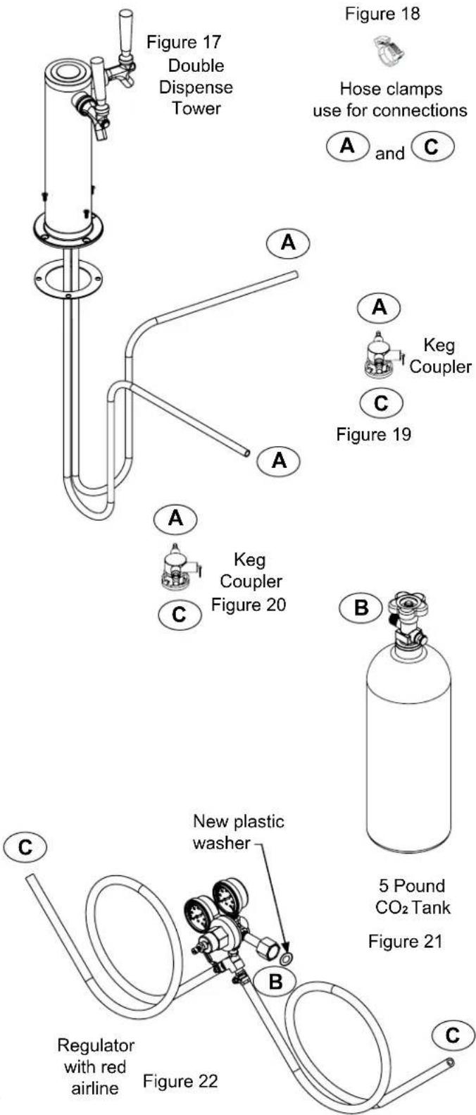
text_image
Figure 17 Double Dispense Tower Figure 18 Hose clamps use for connections A and C A A Keg Coupler C Figure 19 A A Keg Coupler Figure 20 B 5 Pound CO₂ Tank Figure 21 C New plastic washer B Regulator with red airline Figure 22 C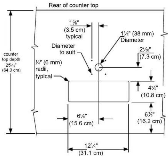
text_image
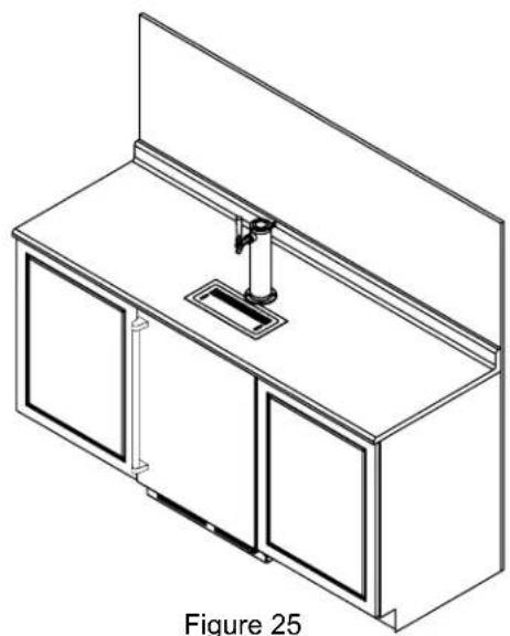
Rear of counter top 1¾" (3.5 cm) typical Diameter to suit ½" (6 mm) radii, typical 1½" (38 mm) Diameter 2½" (7.3 cm) 4¼" (10.8 cm) 6½" (15.6 cm) 6¾" (16.2 cm) 12½" (31.1 cm) counter top depth 25½" (64.3 cm)Figure 23

CAUTION
The cutout dimensions shown in Figure 23 are based on a 25 516 (64.3 cm) deep counter top. Your counter top may be different than this and require other front to back dimensioning. Refer to the product dimensions on page 8 when determining the required dimensions.
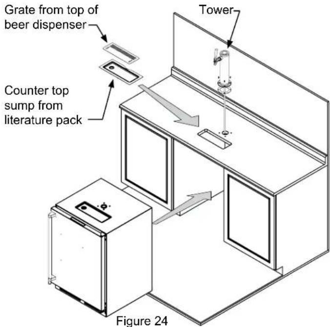
text_image
Grate from top of beer dispenser Tower Counter top sump from literature pack Figure 24-
If you are installing your keg refrigerator under a counter you will need to drill 5 holes in the counter top to mount the tower. The first hole is a 1 12 " diameter hole located at the center of the tower for the beer line, locate approximately 13 12 " (34.3 cm) from the front edge of the counter top (based on a counter top depth of 25 516 "). Next drill the 4 tower mounting holes per the dimensions in Figure 23. The hole diameter is dependent on the counter top material and if screw anchors are required. The screws supplied are in the literature pack and are a #10 x 1" type AB stainless steel screw. Mark and cut the rectangular cutout for the drain sump. After the holes are drilled and the keg refrigerator is in place under the counter top feed the beer line through the tower gasket, the 1 12 " hole in the counter top and the hole in the top of the keg refrigerator. Mount the tower to the counter top with the 4 screws provided. Place the counter top drain sump, from the literature pack, in the rectangular hole with the radius cutout to the rear around the tower and place the grate in the sump.
-
Mount the regulator to the CO _2 tank (connection ^⑧ ) use the new plastic washer you received from the gas supply company. Note that the regulator has left hand threads and has to be turned counterclockwise to tighten. Tighten with the adjustable wrench or the 1 ^1/8 " open end wrench.
-
Connect the red air line(s) from the regulator to the large air line fitting on the keg coupler with a large hose clamp (connection©).
-
Connect the clear beer line from the tower to the small air line fitting on the keg coupler with a small hose clamp (connection A).
natural_image
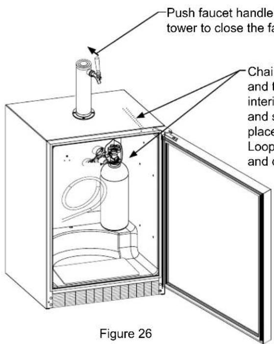
Isometric line drawing of a cabinet with two doors and a central shelf (no text or symbols)- Locate the CO _2 tank in the corner of the refrigerator as shown in Figure 26 and secure with the chain. Close the faucet handle on the tower.
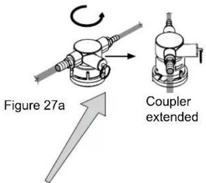
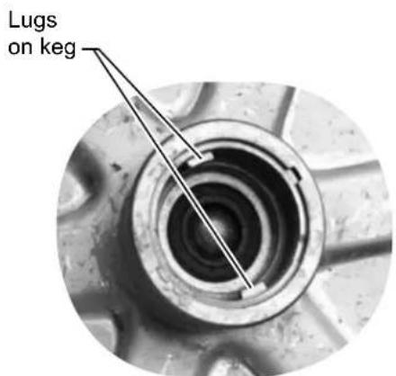
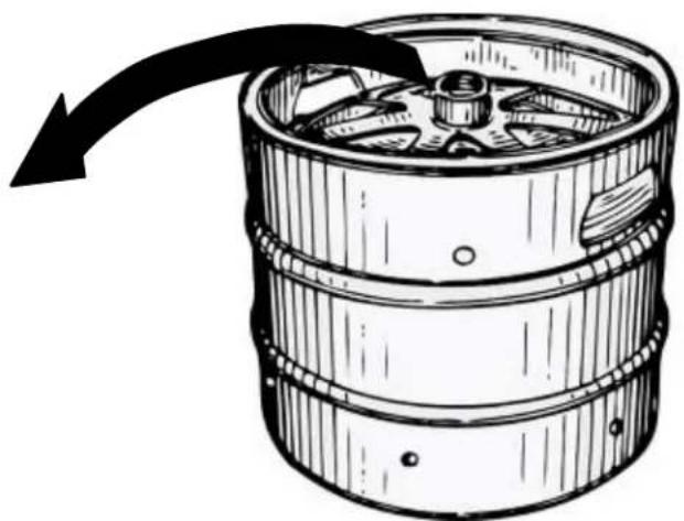
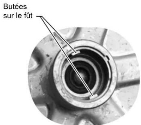
- Hooking up the keg coupler to the keg: Verify the coupler is in the "OFF" position (see Figure 27a). Align the lugs on the keg with the corresponding openings on the keg coupler and turn clockwise until the coupler stops (about 90°). Push down and twist the top of the coupler clockwise to allow gas to enter the keg.
text_image
Push faucet handle tower to close the fa Chair and t interi and s place Loop and o Figure 26-Push faucet handle back toward tower to close the faucet
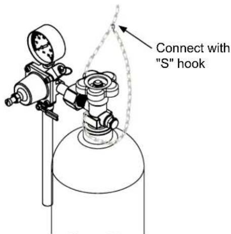
Chain-The chain is fastened and taped to the top of the interior liner. Remove the tape and secure the CO_2 tank in place in the back right corner. Loop chain around top of tank and connect with "S" hook.
text_image
Connect with "S" hookFigure 26a
Rotate the top of the coupler counter clockwise to extend the coupler to the to the "OFF" position.
text_image
Figure 27a Coupler extended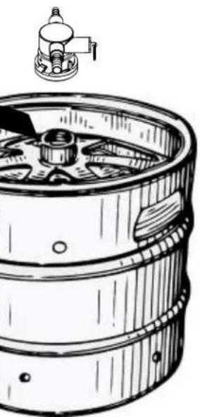
natural_image
Line drawing of a wooden barrel with a small mechanical component above it (no text or symbols)Figure 27
text_image
Lugs on kegFigure 27b
natural_image
Illustration of a wooden barrel with a curved arrow indicating rotation or flow (no text or symbols)CO _2 Regulator (Single Dispense Tower)
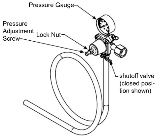
Your beer dispenser comes equipped with a 5 pound CO _2 tank and a single gauge regulator. The gauge reads the pressure being supplied to the beer keg. Follow the procedure below to adjust the pressure to 12 - 14 psi (0.8 to 1 bar) for lager beer or 9 - 12 psi (0.6 to 0.8 bar) for ale's.
To adjust the pressure (Single Gauge):
- Close the shutoff valve at the bottom of the regulator.
- Be sure the faucet handle is closed on the tower (see Figure 26).
- Loosen the lock nut by turning counterclockwise using the 1/2" open end wrench until loose, this will allow adjustment of the pressure adjustment screw.
- With the flat bladed screwdriver turn the adjustment screw clockwise to increase the pressure or counterclockwise to decrease the pressure.
- Open the shutoff valve on the bottom of the regulator. The gauge reading may drop but will return very quickly.
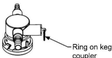
- Pull the ring on the keg coupler to allow the gas to flow momentarily.
- Make any fine adjustments if necessary with the adjustment screw.
- Tighten the locknut with the 12 " open end wrench by turning clockwise o.
text_image
Ring on keg couplerFigure 28
text_image
Pressure Gauge Pressure Adjustment Screw Lock Nut shutoff valve (closed position shown)Figure 29 (Regulator for Single Dispense Tower)
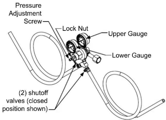
CO _2 Regulator (Double Dispense Tower)
Your beer dispenser comes equipped with a 5 pound CO 2 tank and a dual gauge regulator. The lower gauge should be reading approximately 750 psi (52 bar) when the tank is properly filled and the tank is not in the refrigerator (at room temperature). The tank will read less when chilled. Use this lower gauge as an indicator of how much CO 2 you have left in the tank.
The upper gauge reads the pressure being supplied to the beer keg. Follow the procedure below to adjust the pressure to 12 - 14 psi (0.8 to 1 bar) for lager beer or 9 - 12 psi (0.6 to 0.8 bar) for ale's.
To adjust the pressure (Upper Gauge):
- Close the shutoff valves at the bottom of the regulator.
- Be sure the faucet handle is closed on the tower (see Figure 29).
- Loosen the lock nut by turning ∘ counterclockwise using the 12 " open end wrench until loose, this will allow adjustment of the pressure adjustment screw.
- With the flat bladed screwdriver turn the adjustment screw ⚡ clockwise to increase the pressure or ⚡ counterclockwise to decrease the pressure.
- Open the shutoff valve on the bottom of the regulator. The gauge reading may drop but will return very quickly.
- Pull the ring on the keg coupler to allow the gas to flow momentarily.
- Make any fine adjustments if necessary with the adjustment screw.
- Tighten the locknut with the 12 " open end wrench by turning clockwise o.
text_image
Pressure Adjustment Screw Lock Nut Upper Gauge Lower Gauge (2) shutoff valves (closed position shown)Figure 30 (Regulator for Double Dispense Tower)
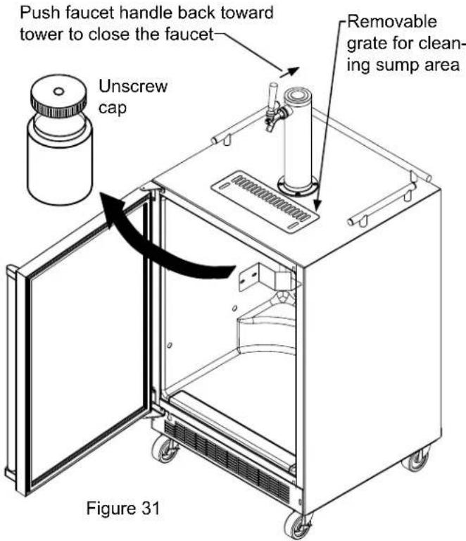
Drain kit (All Models): The drain kit is shipped in place and ready to use. To empty: Pull drain hose out of bottle cap, remove bottle from unit, unscrew cap and discard waste and rinse bottle. Reinstall bottle in unit.
Cleaning the drain sump:
On a free standing beer dispenser remove the grate from in front of the tower, clean with soap and water and dry before reinstalling. Clean the sump area with soapy water and dry. (See figure 31).
On a built in beer dispenser remove the grate and counter top sump, clean with soap and water and dry before reinstalling. Clean the sump area with soapy water and dry. (See Figure 32).
text_image
Push faucet handle back toward tower to close the faucet Unscrew cap Removable grate for cleaning sump area Figure 31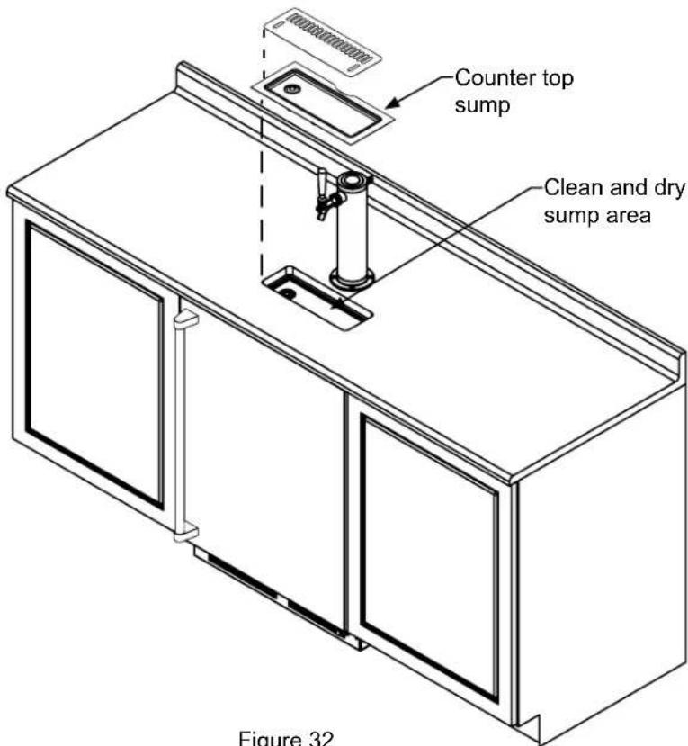
text_image
Counter top sump Clean and dry sump area Figure 32Figure 32
Cleaning and Maintaining Dispensing System
The dispensing system needs to be cleaned between usage to prevent spoilage and/or foul taste in your beer.
Cleaning
Remove the keg coupler from the keg if necessary. Close the gas valve(s) below the regulator, remove both the red gas line(s) and clear beer line(s) from the keg coupler(s) by removing the plastic hose clamps (See Figure 33). Soak and brush the keg coupler in hot water or a sanitizing solution. Rinse thoroughly with clean water. Dry all parts and reassemble.
Hose clamps can be released by a lateral movement to the head.
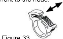
Figure 33
natural_image
Technical line drawing of a mechanical component with no visible text or symbolsFigure 34
Faucet Cleaning
Turn off the gas supply with the shutoff valve(s) under the regulator (see Figure 29 or 30) and open the faucet to relieve the pressure. To remove the faucet from the tower use the spanner wrench provided. Place the pin on the wrench into the hole on the faucet collar and turn clockwise to remove the faucet. (See Figure 35).
Remove the knurled cap from the faucet body just below the handle and pull the handle assembly from the faucet. This will allow the shaft to be removed from the back of the faucet, see Figure 36.
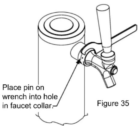
text_image
Place pin on wrench into hole in faucet collar. Figure 35After removing the handle the shaft will slide out the back of the faucet
Figure 36
Unscrew knurled cap on faucet body and remove handle assembly
Soak all faucet parts in hot water or a solution of hot water and a sanitizing solution. Do not use soap. Rinse thoroughly with clean water.
Reassemble faucet, assemble faucet to tower (be sure faucet is in off position), and turn on gas valve.
Front Grille
Be sure that nothing obstructs the required air flow openings in front of the cabinet. At least once or twice a year, brush or vacuum lint and dirt from the front grille area (see page 4).

CAUTION
SHOCK HAZARD: Disconnect electrical power from the appliance before cleaning with soap and water.
Cabinet
The stainless steel cabinet can be washed with either a mild soap and water and thoroughly rinsed with clear water. NEVER use abrasive scouring cleaners. Dry thoroughly with a terry towel.
Interior
Wash interior compartment with mild soap and water. Do NOT use an abrasive cleaner, solvent, polish cleaner or undiluted detergent.
Care of Appliance
- Avoid leaning on the door, you may bend the door hinges or tip the appliance.
- Exercise caution when sweeping, vacuuming or mopping near the front of the appliance. Damage to the grille can occur.
- Periodically clean the interior of the appliance as needed.
In the Event of a Power Failure
If a power failure occurs, try to correct it as soon as possible. Minimize the number of door openings while the power is off so as not to adversely affect the appliance's temperature.
Long term storage / winterization:
- Time to Winterize, when the daily low ambient temperature is at or below 38^ F ( 3.3^ C).

CAUTION
Operating of the unit at ambient temperatures below the recommended Winterization temperature will void your warranty.
- Turn unit off, (see page 9).
- Remove all contents.
- If necessary, move the unit so you can gain access to the rear of the product.
- Unplug the unit from the power outlet.
- It is also recommended that the power to the outlet be turned-off if the circuit is not required for other items during the Winter season.
- Shut-off CO ^2 tank valve.
- Drain beer line(s)
a. Remove keg coupler (sankey tap), (see page 16).
b. Remove faucet on tower, (see page 16).
c. Beer lines will gravity drain.
d. Clean beer line tubing.
- Disassemble faucet and clean, (see page 16).
- Soak and clean Sankey Low-Boy tap, (see page 16).
- When cleaning unit pay particular attention to any cracks and crevices that may have accumulated dirt and debris.
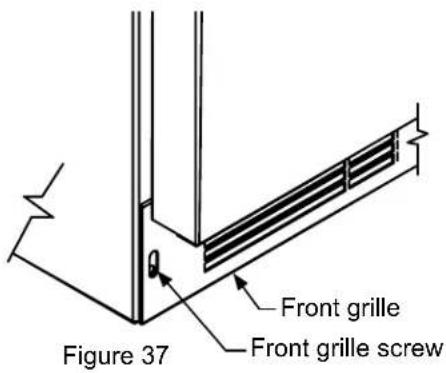
- Remove the front toe-grille, (see Figures 37 and 38), and use a brush and vacuum to clean dirt and debris from beneath the unit.
- Thoroughly clean the toe-grille and re-install on the unit.
- Remove the rear access cover, (see Figure 39), and use a brush and vacuum to clean dirt and debris from the machine compartment.
- If the plastic defrost drain pan located under the compressor contains water, use a sponge to remove as much water as possible
-
Thoroughly clean the rear access cover and re-install on the unit.
-
Wipe down all interior surfaces with anti-bacterial cleaner to be followed with clean rinse water to remove any residual chemicals which could cause staining. Do not use any abrasive cleaners or scouring pads.
- Remove plastic floor protector and stainless steel lower edge guard to clean underneath.
text_image
Figure 37 Front grille Front grille screw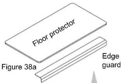
text_image
Floor protector Figure 38a Edge guard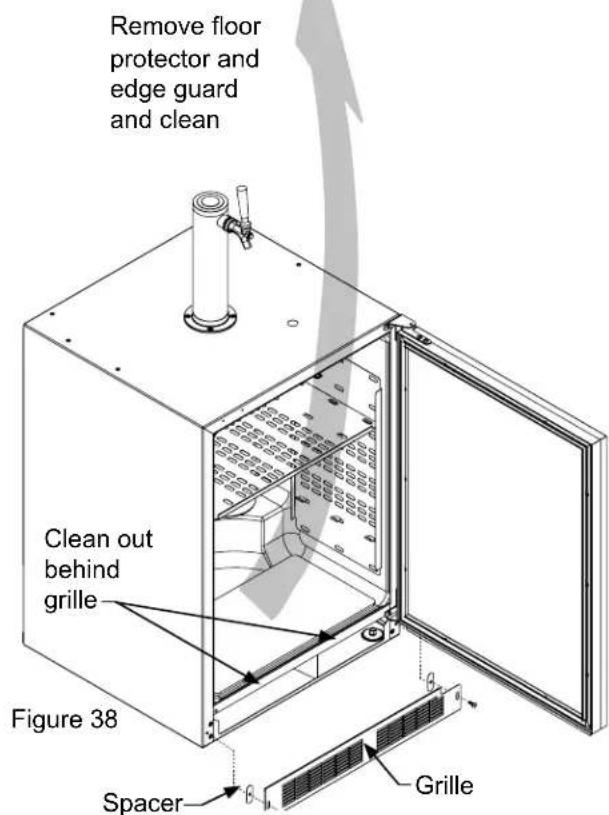
text_image
Remove floor protector and edge guard and clean Clean out behind grille Figure 38 Spacer Grille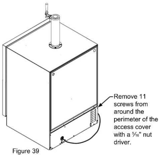
text_image
Remove 11 screws from around the perimeter of the access cover with a 5/16" nut driver. Figure 39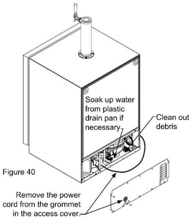
text_image
Soak up water from plastic drain pan if necessary Clean out debris Figure 40 Remove the power cord from the grommet in the access cover.- Leave door open and allow to completely dry out before closing door.
- Thoroughly clean the door gasket with anti-bacterial cleaner to be followed with clean rinse water to remove any residual chemicals.
- Thoroughly clean the exterior with a cleaner approved for stainless steel. Do not use any abrasive cleaners or scouring pads.
- Any mounting hardware / fasteners that are showing signs of corrosion should be replaced.
- Once the exterior has been thoroughly cleaned, you may want to apply a coating of car wax to help protect against spotting from moisture, dirt, and debris that may accumulate on the surfaces during the Winterization period.
After completion of the above, you may choose to store the unit indoors, although this is not required.
Start-Up After Long-Term Storage:
- Connect the unit to electrical power.
- If stored outside, it is recommended that the unit again be thoroughly inspected per the storage instructions above to address any dirt or debris from the weather and/or animals/insects.
- Turn unit on and confirm your desired control settings.
- Allow 24-hrs for the unit to stabilize before loading contents.
Background
Stainless steel does not stain, corrode, or rust as easily as ordinary steel, but it is not stain or corrosion proof. Stainless steels can discolor or corrode if not maintained properly.
Stainless steels differ from ordinary carbon steels by the amount of chromium present. It is this chromium that provides an invisible protective film on the surface called chrome-oxide. This protective chrome-oxide film on the surface can be damaged or contaminated, which may result in discoloration, staining, or corrosion of the base metal.
Care & Cleaning
Routine cleaning of the stainless steel surfaces will serve to greatly extend the life of your product by removing contaminants. This is especially important in coastal areas which can expose the stainless to severe contaminants such as halide salts, (sodium chloride).
It is strongly recommended to periodically inspect and thoroughly clean crevices, weld points, under gaskets, rivets, bolt heads, and any locations where small amounts of liquid could collect, become stagnant, and concentrate contaminates. Additionally, any mounting hardware that is showing signs of corrosion should be replaced.
Frequency of cleaning will depend upon the installation location, environmental, and usage conditions.
Choosing a Cleaning Product
The choice of a proper cleaning product is ultimately that of the consumer, and there are many products from which to choose. Depending upon the type of cleaning and the degree of contamination, some products are better than others.
Typically the most effective and efficient means for routine cleaning of most stainless steel products is to give the surfaces a brisk rubbing with a soft cloth soaked in warm water and a gentle detergent, or mild mixture of ammonia. Rubbing should, to the extent possible, follow the polish lines of the steel, and always insure thorough rinsing after cleaning.
Although some products are called "stainless steel cleaners," some may contain abrasives which could scratch the surface, (compromising the protective chrome-oxide film), and some many contain chlorine bleach which will dull, tarnish or discolor the surface if not completely removed.
After the stainless surfaces have been thoroughly cleaned, a good quality car wax may be applied to help maintain the finish.
Note: Stainless steel products should never be installed, or stored in close proximity to chlorine chemicals.
Whichever cleaning product you chose, it should be used in strict accordance with the instructions of the cleaner manufacturer.
The following suggestions will minimize the cost of operating your refrigeration appliance.
- Do not install your appliance next to a hot appliance (cooker, dishwasher, etc.), heating air duct, or other heat sources.
- Install product out of direct sunlight.
- Ensure the front grille vents at front of appliance beneath door are not obstructed and kept clean to allow ventilation for the refrigeration system to expel heat.
- Plug your appliance into a dedicated power circuit. (Not shared with other appliances).
- When initially loading your new product, or whenever large quantities of warm contents are placed within refrigerated storage compartment, minimize door openings for the next 12 hours to allow contents to pull down to compartment set temperature.
- Maintaining a relatively full storage compartment will require less appliance run time than an empty compartment.
- Ensure door closing is not obstructed by contents stored in your appliance.
- Allow hot items to reach room temperature before placing in product.
- Minimize door openings and duration of door openings.
- Use the warmest temperature control set temperature that meets your personal preference and provides the proper storage for your stored contents.
- When on vacation or away from home for extended periods, set the appliance to warmest acceptable temperature for the stored contents.
- Set the control to the "off" position if cleaning the appliance requires the door to be open for an extended period of time.
Before You Call for Service
If the appliance appears to be malfunctioning, read through this manual first. If the problem persists, check the trouble-shooting guide below. Locate the problem in the guide and refer to the cause and its remedy before calling for service. The problem may be something very simple that can be solved without a service call. However, it may be required to contact your dealer or a qualified service technician.

WARNING
Electrocution Hazard
- Never attempt to repair or perform maintenance on the appliance until the main electrical power has been disconnected. Turning the appliance control "OFF" does not remove electrical power from the unit's wiring.
- Replace all parts and panels before operating.
How to Obtain Service:
For warranty service, please contact your local service provider or DCS Customer Care at (888) 936-7872. Before you call, please have the following information ready:
- Model Number (the serial plate is located on the upper left side, inner wall).
- Serial Number (the serial plate is located on the upper left side, inner wall).
- Code (the serial plate is located on the upper left side, inner wall).
- Date of installation
• A brief description of the problem
Your satisfaction is of the utmost importance to us. If a problem cannot be resolved to your satisfaction, please write or email us at:
Write:
Fisher & Paykel and DCS
Appliances Inc
695 Town Centre Drive, Suite #180 Costa Mesa
CA 92626-1902
USA
Email:
customer.care@fisherpaykel.com
| Problem Possible Cause | Remedy | |
| Appliance not cold enough(See “Adjusting the temperature” on page 9) | Control set too warmContent temperature not stabilized. | Adjust temperature colder. Allow 24 hours for temperature to stabilize. |
| Excessive usage or prolonged door openings. | Allow temperature to stabilize for at least 24 hours. | |
| Airflow to front grille blocked. | Airflow must not be obstructed to front grille. See “clearances” on page 4. | |
| Door gasket not sealing properly. | Replace door gasket. | |
| Appliance too cold(See “Adjusting the Temperature” on page 9) | Control set too cold | Adjust temperature warmer.Allow 24 hours for temperature to stabilize. |
| Door gasket not sealing properly. | Replace door gasket. | |
| Noise or Vibration • Appliance not level | Level appliance, see “Leveling Legs” on page 4. | |
| Fan hitting tube obstruction. | Contact a qualified service technician. | |
| Appliance will not run. • Appliance turned off | Turn appliance on. See “Starting your appliance” on page 9. | |
| Plug in power cord. | ||
| Check house circuit. | ||
Limited Warranty
When you purchase any new DCS Refrigeration Product, you automatically receive a Two Year Limited Warranty covering parts and labor for servicing within the 48 mainland United States, Hawaii, Washington, D.C. and Canada. In Alaska the Limited Warranty is the same except that you must pay to ship the Product to the service shop or for the service technician's travel to your home. Products for use in Canada must be purchased through the authorized Canadian distribution channel to ensure regulatory compliance.
You receive an additional Three Year Limited Warranty (for a total of Five Years) covering parts for the sealed refrigeration system (compressor, evaporator, condenser, filter dryer, and connecting tubing) within the 48 mainland United States, Hawaii, Washington, D.C. and Canada. In Alaska the Limited Warranty for the sealed refrigeration system is the same except that you must pay to ship the Product to the service shop or the service technician's travel to your home.
If the product is installed in a motor vehicle, boat or similar mobile facility, you receive the same two year warranty, but you must bring the vehicle, boat or mobile facility containing the product to the service shop at your expense, or pay the service technicians to travel to the location of the product.
Fisher & Paykel Undertakes to:
Repair without cost, with limited expectations described herein, to the owner either for material or labor any part of the Product, the serial number of which appears on the Product, which is found to be defective. In Alaska, you must pay to ship the Product to the service shop or for the service technician's travel to your home.
If we are unable to repair a defective part of the Product after a reasonable number of attempts, at our option we may replace the part or the Product, or we may provide you a full refund of the purchase price of the Product (not including installation or other charges).
This warranty extends to the original purchaser and any succeeding owner of the Product during the term of warranty, for products purchased for ordinary single-family home use.
All service under this Limited Warranty shall be provided by Fisher & Paykel Appliances Inc. or its Authorized DCS Service Agent during normal business hours.
There is no warranty for commercial purchase or use.
Limited Warranty
How Long Does this Limited Warranty Last?
Our liability under this Limited Warranty expires Two Years from the date of purchase of the Product by the first consumer.
Our liability for repair of defects in any sealed refrigeration system (compressor, evaporator, condenser, filter dryer, and connecting tubing) extends an additional Three Years, for a total of Five Years from the date of purchase of the Product by the first consumer.
Our liability under any implied warranties, including the implied warranty of merchantability (an unwritten warranty that the Product is fit for ordinary use) also expires Two Years (or such longer period as required by applicable law) from the date of purchase of the Product by the first consumer. Some states do not allow limitations on how long an implied warranty lasts, so this limit on implied warranties may not apply to you.
Fisher & Paykel will honor any warranty required by the law of the particular country or state in which the product is sold.
This Warranty Does Not Cover
A. Service calls that are not related to any defect in the Product. The cost of a service call will be charged if the problem is not found to be a defect of the Product. For example:
- Correct faulty installation of the Product.
- Instruct you how to use the Product.
- Replace house fuses, reset circuit breakers, correct house wiring or plumbing, or replace light bulbs.
- Correct fault(s) caused by the user.
- Change the set-up of the Product.
- Unauthorized modifications of the Product.
- Noise and vibration that is considered normal e.g. drain sounds, regeneration noises and user warning beeps.
- Correcting damage caused by pests e.g. rats, cockroaches etc.
- Used in commercial applications.
B. Defects caused by factors other than:
- Normal domestic use or
- Use in accordance with the Product's Use and Care Guide.
C. Defects to the Product caused by accident, neglect, misuses, fire, flood or Act of God.
D. The cost of repairs carried out by non-authorized repairers or the cost of correcting such unauthorized repairs.
E. Travel Fees and associated charges incurred when the product is installed in a location with limited or restricted access.(i.e. airplane flights, ferry charges, isolated geographic areas).
F. Normal recommended maintenance as set forth in the Product's Use and Care Guide. If you have an installation problem contact your dealer or installer. You are responsible for providing adequate electrical, exhausting and other connection facilities.
This product has been designed for use in a normal domestic (residential) environment.
This product is not designed for commercial use (whatsoever). Any commercial use by a customer will terminate/affect this products limited warranty.
We are not responsible for consequential or incidental damages (including without limitation the cost of repairing or replacing other property damaged if the Product is defective or any of your expenses caused if the Product is defective). Some states do not allow the exclusion or limitation of incidental or consequential damages, so the above limitation or exclusion may not apply to you.
How to get service
Please read this Use and Care Guide. If you then have any questions about operating the Product, need the name of your local DCS Authorized Service Agent, or believe the Product is defective and wish service under this Limited Warranty, please contact your dealer or call us at:
TOLL FREE 1-888-936-7872 or contact us through our web site: www.dcsappliances.com
You may be required to provide reasonable proof of the date of purchase of the Product before the Product will be serviced under this Limited Warranty.
Commercial use
This warranty applies to appliances used in residential applications; it does not cover their use in commercial situations.
No other warranties
This Limited Warranty is the complete and exclusive agreement between you and Fisher & Paykel Appliances Inc. regarding any defect in the Product and no other express warranty has been made or will be made on behalf of Fisher & Paykel. None of our employees (or our Authorized Service Agents) are authorized to make any addition or modification to this Limited Warranty.
Warrantor: Fisher & Paykel Appliances, Inc.
If you need further help concerning this Limited Warranty, or to make a claim under this warranty, please call us at the above number, or write to:
Fisher & Paykel and DCS
Appliances Inc
695 Town Centre Drive, Suite #180 Costa Mesa
CA 92626-1902
USA
This Limited Warranty gives you specific legal rights, and you may also have other rights which vary from country to country and from state to state.
Fisher & Paykel Appliances Inc. is a leading manufacturer of premium quality cooking and specialty appliances under the Fisher & Paykel and DCS brands.
Ensemble d'évacuation....37
text_image
Prohibition sign showing a crossed-out electrical component with 'Q' symbols and a diagonal lineFigure 4

natural_image
Simple line drawing of an electrical plug and two socket socket (no text or symbols)Figure 5

MISE EN GARDE
text_image
Alarm 40° F Set Colder Warmer Free and More (Yes or Hold) ON/OFF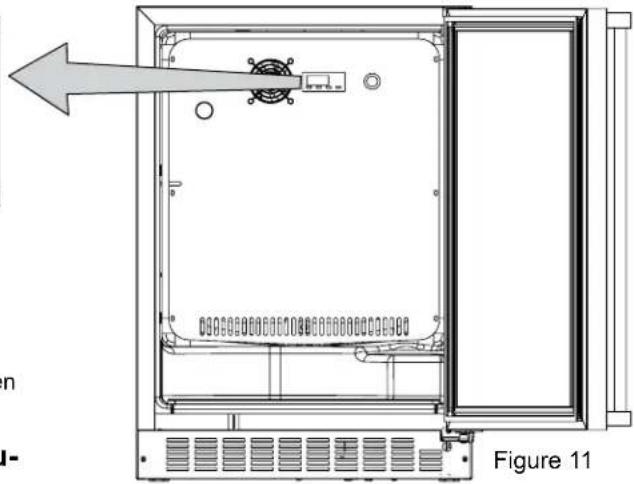
natural_image
Technical line drawing of an open electrical enclosure with internal components and a directional arrow (no text or symbols)natural_image
Simple line drawing of a cylindrical container with a cap on top (no text or symbols)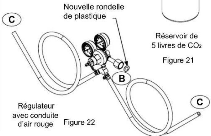
natural_image
Isometric line drawing of a cabinet with three doors and a central support (no text or symbols)natural_image
Line drawing of a wooden barrel with a mechanical component above it (no text or symbols)Figure 27
natural_image
Illustration of a wooden barrel with a curved arrow indicating rotation or flow (no text or symbols)Fisher & Paykel and DCS
Appliances Inc
695 Town Centre Drive, Suite #180 Costa Mesa
CA 92626-1902
USA
customer.care@fisherpaykel.com
Fisher & Paykel and DCS
Appliances Inc
695 Town Centre Drive, Suite #180 Costa Mesa
CA 92626-1902
USA
text_image
DCS by Fisher&PaykelQuality provided by Fisher & Paykel Appliances Inc.
Fisher & Paykel and DCS Appliances Inc
695 Town Centre Drive, Suite #180 Costa Mesa
CA 92626-1902
USA
Customer Care: 888.936.7872
Fax: 714.372.7003
As product improvement is an ongoing process, we reserve the right to change specifications or design without notice.
Fisher & Paykel and DCS Appliances Inc
695 Town Centre Drive, Suite #180 Costa Mesa
CA 92626-1902
USA