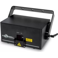
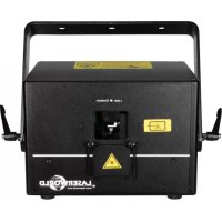
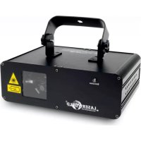
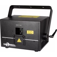
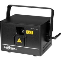
DS1000RGB MK3 - Lamp Laserworld - Free user manual and instructions
Find the device manual for free DS1000RGB MK3 Laserworld in PDF.
| Product type | Laser show lamp (class 4) |
| Model | DS1000RGB MK3 |
| Brand | Laserworld |
| Dimensions | 200 x 140 x 110 mm |
| Weight | 2.8 kg |
| Power supply | 85-250 V AC, 50/60 Hz, consumption 40 W |
| Laser sources | Diodes: red (638 nm) 180 mW, green (520 nm) 120 mW, blue (450 nm) 700 mW |
| Total guaranteed power | 900 mW |
| Scanner | 30 kpps @ 8°, max scanning angle 45° |
| Operating modes | ILDA, DMX, standalone, music, master-slave, ArtNet, network (ShowNET/Pangolin FB4) |
| Network connectivity | Ethernet (RJ45) for direct control via Showeditor/Showcontroller software or FB4 |
| Internal memory | SD card for storing ILDA files (up to 255 files) |
| Safety functions | Key switch, interlock connector, scan safety (SFS), protective fuse |
| Available settings | X/Y inversion, microphone sensitivity, color power (R/G/B), scan speed, safety zone |
| Operating temperature | +10°C to +35°C (without condensation) |
| Warranty | Conditional: intact warranty sticker, compliant use |
| Intended use | Professional use (show and display) according to decree n°2007-665 |
| Delivery contents | 1 projector, 2 keys, instruction manual, hex key, interlock bridge, power cable |
| Recommended maintenance | Clean fans and fins, avoid humidity and heat, use a flight case for transport |
Frequently Asked Questions - DS1000RGB MK3 Laserworld
User questions about DS1000RGB MK3 Laserworld
0 question about this device. Answer the ones you know or ask your own.
Ask a new question about this device
Download the instructions for your Lamp in PDF format for free! Find your manual DS1000RGB MK3 - Laserworld and take your electronic device back in hand. On this page are published all the documents necessary for the use of your device. DS1000RGB MK3 by Laserworld.
USER MANUAL DS1000RGB MK3 Laserworld
DS-1000RGB | DS-2000RGB | DS-3000RGB
DS-1800G | DS-3000G
DS-1600B | DS-5500B
Please spend a few minutes to read this manual fully before operating this laser!
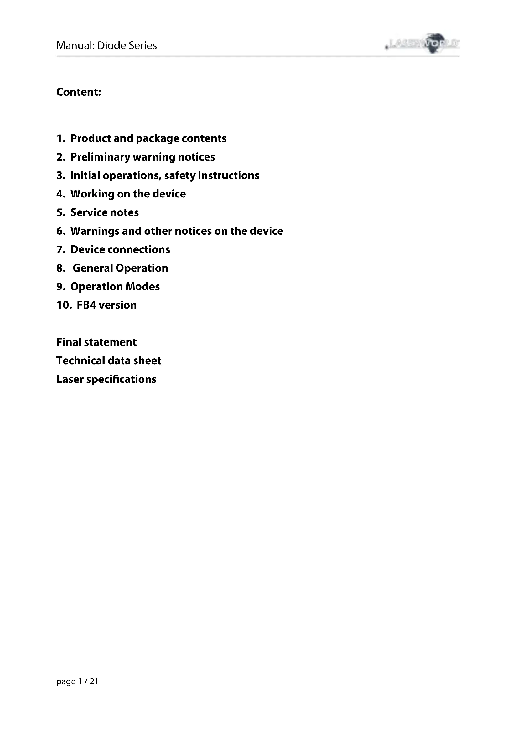
ShowNET inside - the multi-feature laser mainboard
Network Control:
For network control (connecting the device to a Computer) please have a look at chapter 9, "Operation Modes" -> 4, "Network operation"
Netzwerkbetrieb:
Thank you for purchasing this Laserworld product. Due to continual product developments and technical improvements, Laserworld (Switzerland) AG reserves the right to make modifications to its products. This manual and its content have been made with due care but Laserworld (Switzerland) AG cannot however, take any responsibility for any errors, omissions or any resulting damages forthwith. The brands and product names mentioned in this manual are trade marks or registered trademarks of their respective owners.
- Product and package contents
- Preliminary warning notices
- Initial operations, safety instructions
- Working on the device
- Service notes
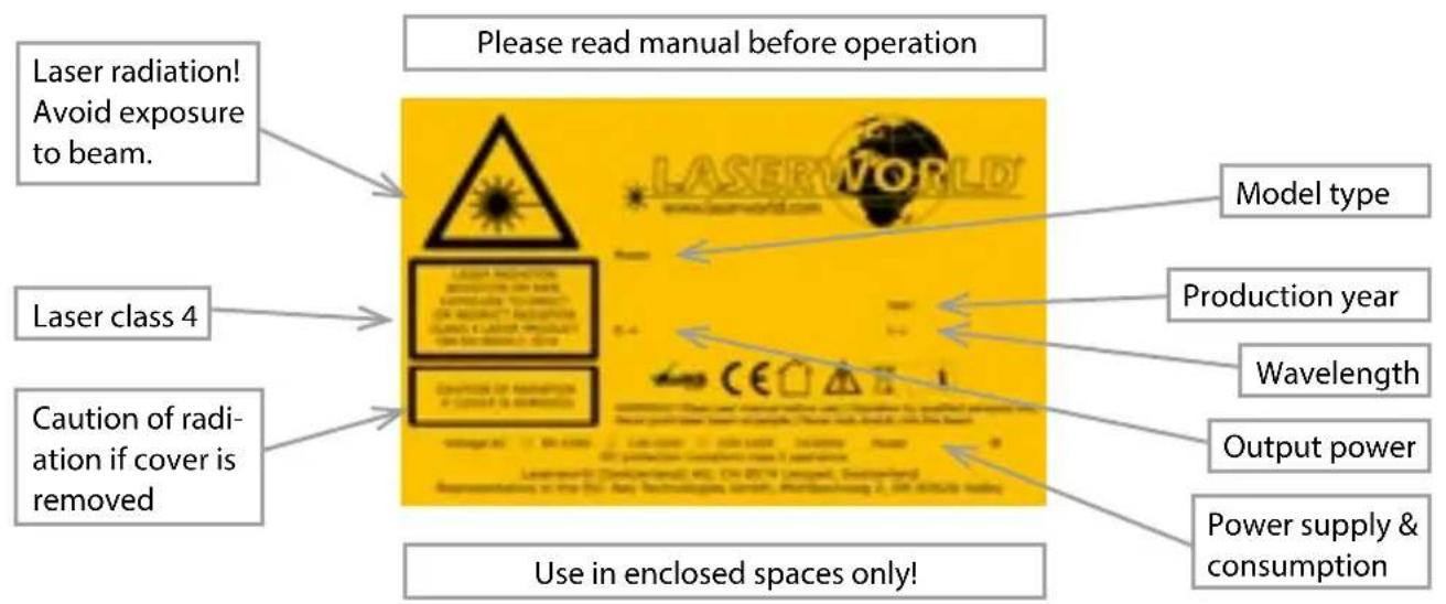
6.Warnings and other notices on the device - Device connections
- General Operation
- Operation Modes
- FB4 version
Final statement
Technical data sheet
Laser specifications
1. Product and package contents
Please check if all listed parts are included and undamaged. Included in delivery:
1x laser projector 2x keys 1x manual
1x power cable 1x interlock bridge 1x hex key
2. Preliminary warning notices
- Please use this device only according to these operating instructions.
- Do not use the device if there are any visible damages on housing, connector panels, power supplies or power cords.
- This device must not be permanently connected to mains. Disconnect it from mains or use the power button to switch if off if not in use.
- Never look directly into the light source of a laser projector. Danger of damage to the eyes or even blindness in extreme circumstances!
- Do not operate the device at high humidity or in the rain or in dusty environments.
- Protect device against dripping or splashing water. Do not place any liquid filled containers near to this device.
Any warranty claims are void if the warranty label is removed or tampered with in any way.
3. Initial operations, safety instructions
- Make sure to use correct voltage; see information on device & in this manual.
- Make sure that the device is not connected to mains during installation.
- Installation has to be done by technical experienced and qualified persons according to safety regulations of the respective country.
- Always ensure that maximum permissible exposure (MPE) is not exceeded in areas accessible to the public or members of staff.
-
In some countries an additional inspection by technical control institutes could be necessary.
-
Connect an easily accessible interlock connector or circuit breaker to the projector.
- The power supply should be easily accessible.
- When installing the laser mount it with a minimum distance of 15cm from walls and objects.
-
For safe setup e.g. on walls or ceilings please use a safety cord. The safety cord should be able to withstand tenfold the weight of the device. Please follow the accident prevention regulations of professional associations and/or comparable regulations for accident prevention.
-
If the device has been exposed to great temperature changes, do not switch it on immediately. Condensation (or any moisture/water formed) may damage this device.
-
Never use dimmer, RC or other electronically switched sockets. Whenever possible, do not use the laser projector together with large appliances (especially fog machines) on the same mains!
-
Ensure sufficient ventilation and do not place the device on any warm or heat radiating surface. Especially the ventilation openings must not be covered!
-
Ensure that device does not get overheated. Make sure that the device is not exposed to spotlights (especially moving heads). Heat of spotlights could overheat laser in a little while and leads to a degradation of performance.
-
This unit is intended for indoor use only.
4. Working on the device
-
This product has no user serviceable parts inside and should only be maintained and serviced by a qualified engineer.
-
Be sure that the mains plug is not connected to the power supply while installing the device.
-
Take off all reflecting things like rings, watches, etc. before starting to work with or at the projector.
-
Only use non-reflecting tools to work on device.
-
Wear protective clothing (like goggles, gloves etc.) according to laser power and wavelength of the laser.
5. Service notes
-
Moisture and heat can reduce lifetime of the laser system dramatically and expires any warranty claim.
-
Quick on/off switching of this device will reduce durability of the laser diode dramatically.
-
Avoid sharp knocks and shocks to this device an endsure sufficient protection during transportation. Look after your Laserworld product.
To increase durability of your laser, protect device against overheating:
-
Always ensure sufficient ventilation.
-
Do not face spotlights (especially moving heads) to the device.
-
Check temperature after approx. 30 minutes with each new installation. If necessary install the projector at a placewithdifferenttemperatures.
-
Keep the device dry. Protect it from moisture, rain and damp.
-
Switch off device when it is not needed. Diodes are switched on and can wear out even if there is no visible laser output.
-
Please ensure the fans and heatsinks are clear from dust and debris otherwise the risk of overheating may occur. If the unit and airways appear to be blocked then please contact a qualified service engineer to maintain and service the product.
-
Removal of the warranty label as well as damages to the device caused by improper handling, neglect of the safety instructions and service notes will void the warranty.
6.Warnings and other notices on the device
7. Device connections
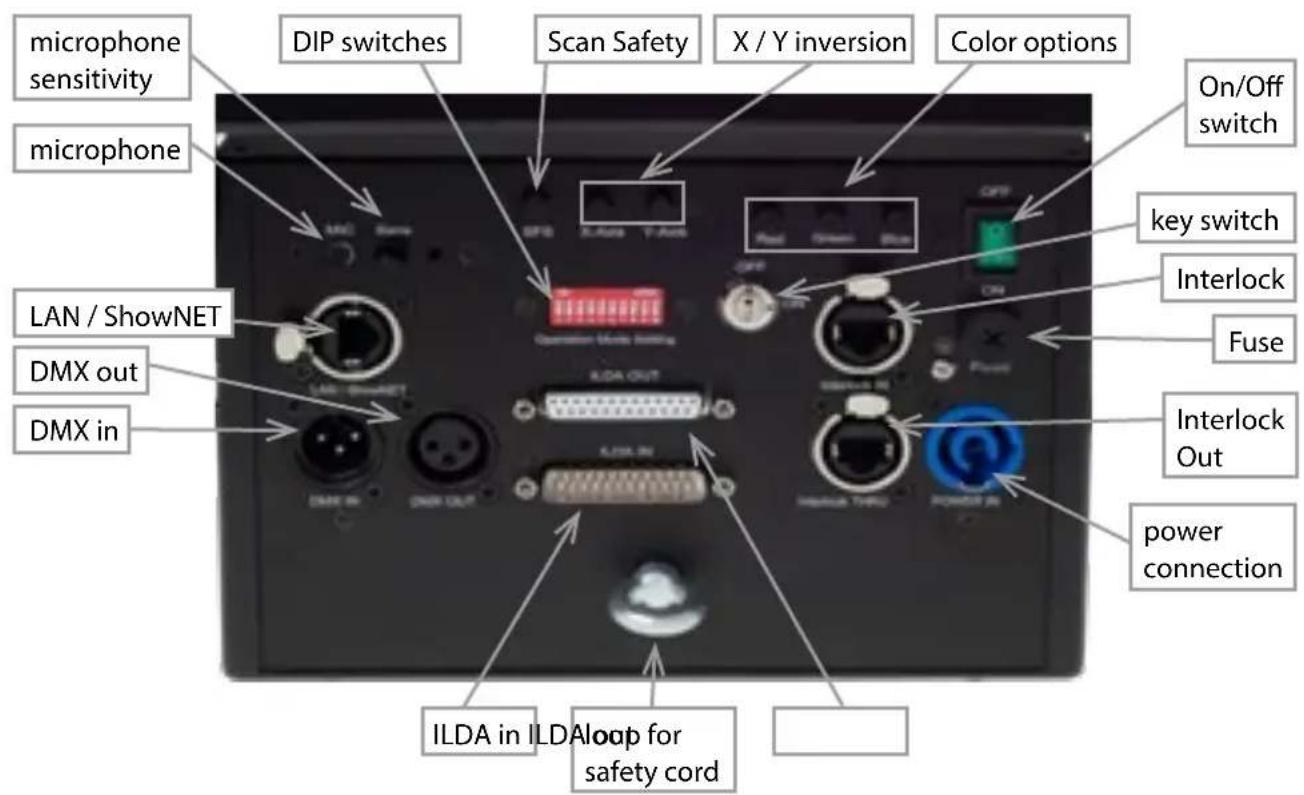
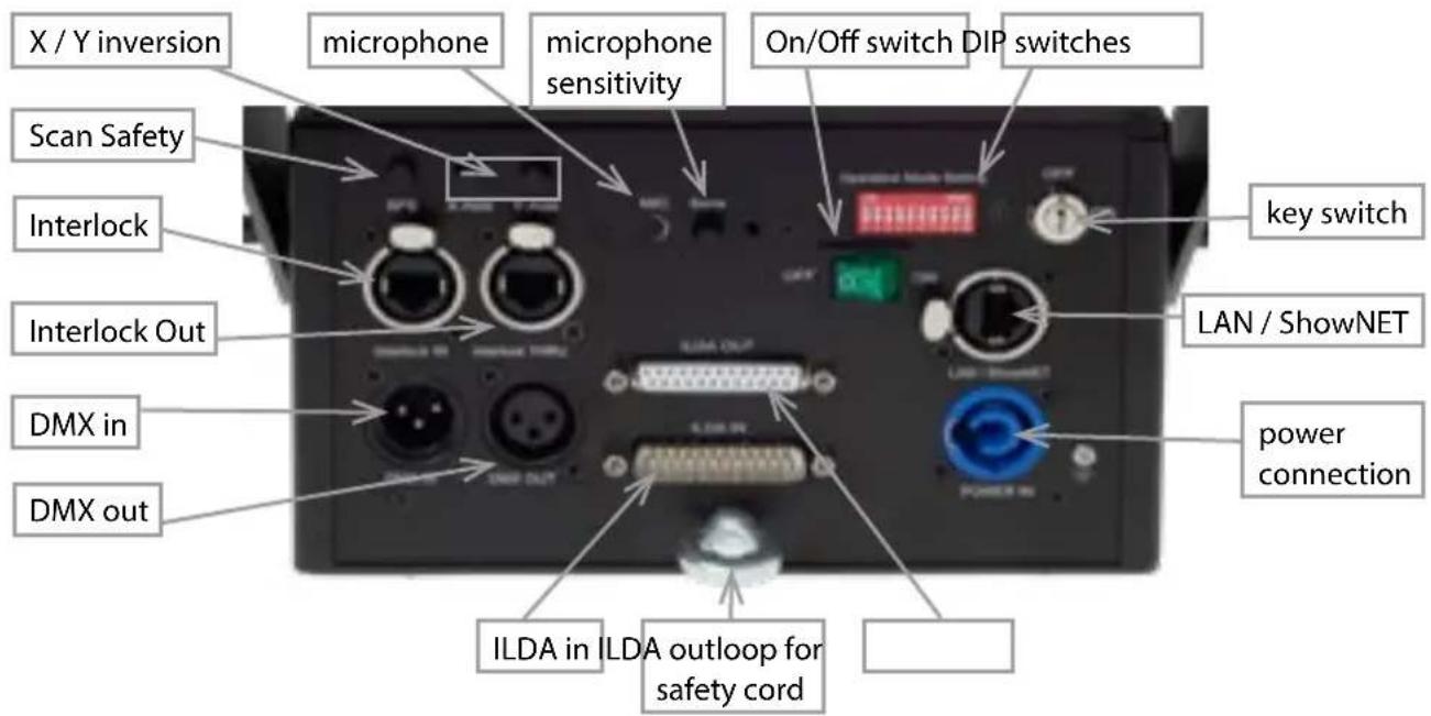
DS-1000RGB
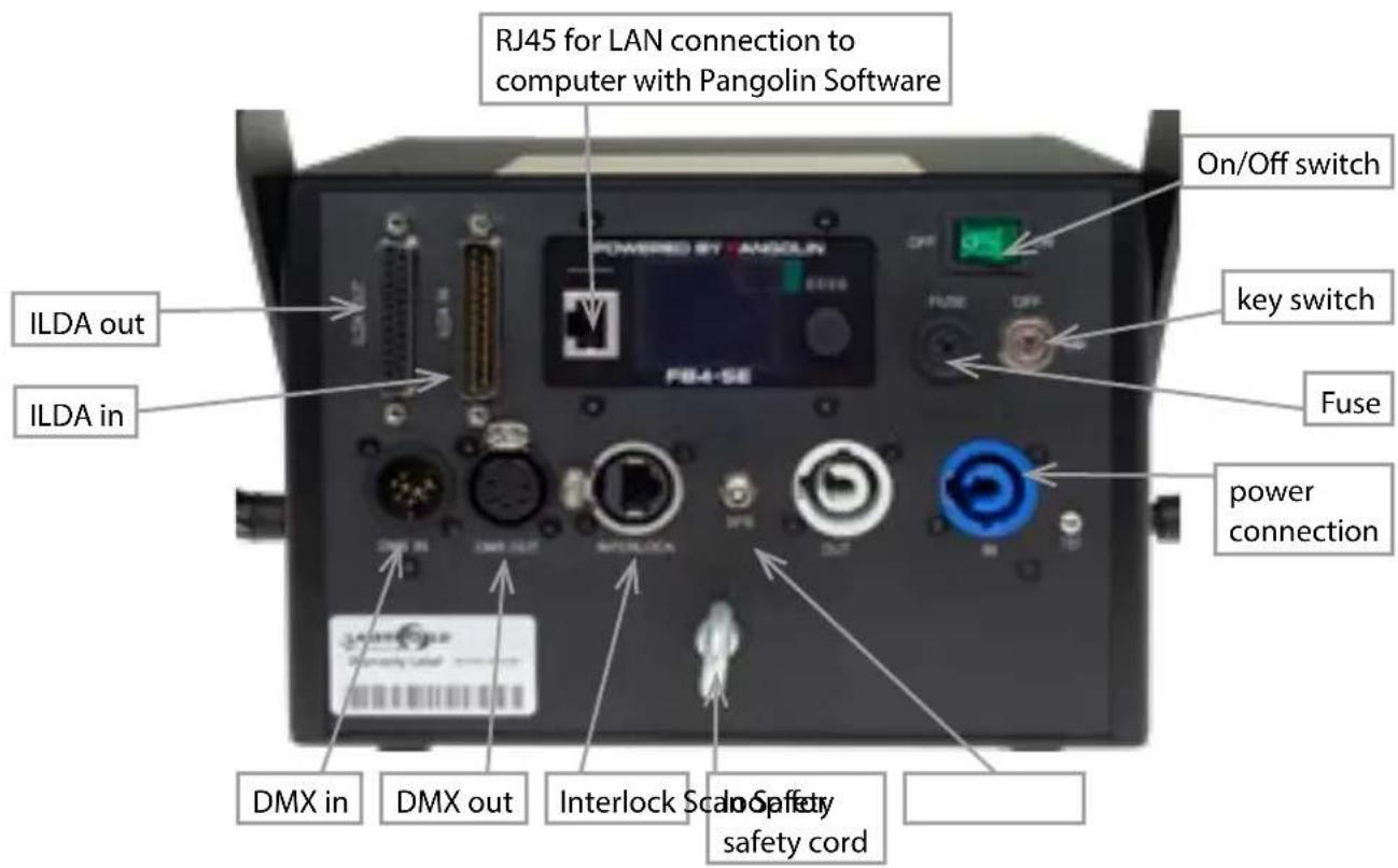
FB4 version
8. General Operation
1. Power
Connect the power cord to the device and to the mains. Make sure that your device is provided with the correct voltage. Wrong voltage could lead to irreparable damages. Please find the correct voltage data in the synoptical table at the end of this manual. Make sure that the device is not directed to people or inflammable objects during installation. To start the device, connect the interlock bridge, insert the key and switch it on, and switch the device on. The "Emission - Laser on" LED at the front side of the device begins to light up when the device is ready for use.
2. Key Switch
There is a key switch at the back of the laser system. Please plug the key to the switch and turn it on. The laser device only runs when the key is inserted and switched on. Prevent misuse! Unplug the key when the laser is unattended to prevent misuse of the system.
3. Fuse
There is a fuse at the back side of the device. If the fuse should blow, please exchange it with a new one. If the problems recurs, please contact your dealer or the Laserworld service department.
4. Safety Presets
This device has an integrated Scan Safety (SFS). Is the Scan Safety active (on), single beams are prevented. If the Scan Safety is switched off, it is possible to create full power single beams - be careful!
Operating the laser system with disabled SFS may not be allowed in some countries.
Always ensure that maximum permissible exposure (MPE) is not exceeded in areas accessible to the public or members of staff.
5. X/Y Inversion
Use the X, Y, and/or X/Y buttons to invert the beams resp. patterns on the x-axis and/or y-axis.
6. Microphone Sensitivity
Set the microphone sensitivity by the, Sens' knob. This setting is needed for music mode / sound sensitive operation.
7. Colors (not available for DS-1000RGB)
Use the,red',green' and,blue' knobs to control the intensity per output color channel.
8. Modes / Functions
The different operation modes can be selected with using the DIP switches at the back of the device. Any change of the operation mode requires a restart of the device (switch the device off and on again or disconnect power and reconnect it again). Do not change any DIP switch settings during operation. Random and dangerous laser output can occur.
9. Turn device off
To turn off the device, use the power button (,OFF) , turn the key to ,OFF' and disconnect the power cable from the mains.
9. Operation Modes
(Firmware version: 20190520x - Admin tool: v1.33)
This laser system can be operated in many different operation modes. It is possible to directly control the laser system via computer and laser show software as well as to trigger effects stored to the internal SD card via DMX/ArtNet consoles, in stand-alone mode or in sound-to-light mode. It is also possible to use the laser system as receiver for ILDA streaming signals from external ShowNET interfaces.
1. Download admin tool
For testing the show laser system and for other purposes, like uploading ILDA files to the integrated SD card, download the admin tool here:
https://www.laserworld.com/shownet_mainboard
Open the „ShowNET-Admin_Tool.exe" whenever this manual refers to the admin tool.
IMPORTANT: It's not possible to access the admin tool, when you are accessing the laser system via software (Showeditor, Showcontroller, etc.). When opening the admin tool while accessing the laser system in a non-direct-control operation mode, the admin tool asks to press on a button to switch to network mode for manual control.
2. Direct computer control
a) ILDA control with external DAC interface
The laser system can be controlled via ILDA control signal. There are an ILDA-in (ILDA input) and an ILDA-thropugh connector at the back side of the device. Connect the laser system to the control interface (DAC) by using an ILDA cable. Do not connect the laser to the standard parallel port at the computer, but always use an appropriate ILDA interface. After that the laser can becontrolled by a show laser control software. Use the ILDA-through connector to daisy-chain the ILDA signal to another laser system.
As this laser system has an integrated DAC interface as mainboard (ShowNET) it is possible to directly control the laser via LAN without the need of ILDA cables or an external DAC interface.
b) Direct operation via laser show software, with LAN connection
(1) SHOWEDITOR - free laser show software
This laser system comes with an integrated network interface. The Showeditor laser software is included with this ShowNET mainboard for free. It is a full feature laser control software with LIVE and Timeline control mode and many free laser shows included in delivery.
Use standard ethernet cable (RJ45 standard) to connect the LAN port of the show laser system to the computer. Standard network switches can be used to connect multiple laser systems at once.
The software can be downloaded for free on:
https://www.showeditor.com
After downloading and installing the software, open the .exe file on the computer and use the software to operate the show laser system.
Details on installation and use of the software please find on the aforementioned website.
(2) SHOWCONTROLLER - professional laser show and multimedia control software suite
The integrated ShowNET mainboard fully supports the direct control of the laser via Showcontroller as well. Showcontroller is a mightly software tool with many professional features. It is very intuitive and thus easy to get started with, too.
The Software and a Demo Version can be downloaded on:
https://www.showcontroller.com
A license can be obtained from where this laser has been purchased.
3. Trigger ILDA files on the internal SD card and own effects
This laser system has an integrated memory (SD card) that can hold ILDA files with laser frames and animations that can be triggered in different ways. It is possible to just use the standard files that come with delivery or change the files to new, custom ones.
a) Upload own ILDA files to the integrated SD card
Besides the possibility to just upload *.ild files to the SD card with a standard card reader, it is also possible to remotely load ILDA files to the integrated SD card via LAN without having to open the device and extract the SD card from the mainboard.
To change the ILDA files, open the admin tool and select the tab ,SD Card' as shown in the picture below:
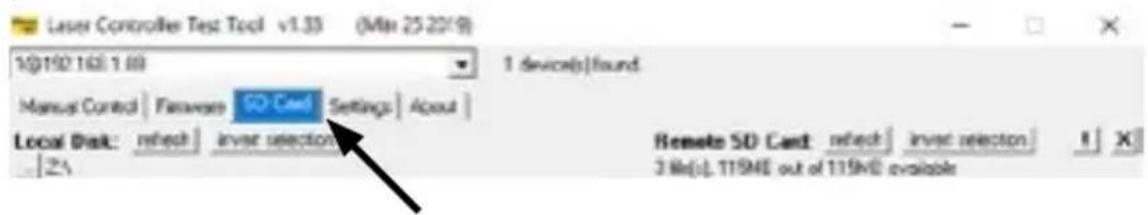
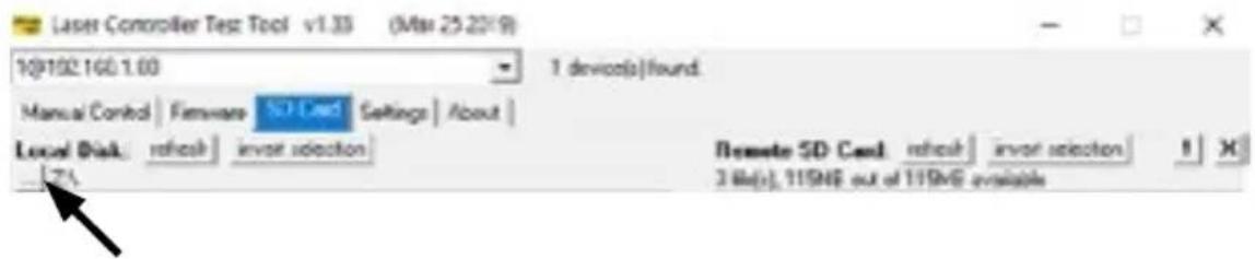
Select the folder with the ILDA files on the local hard drive by clicking on the button with the three points on it:
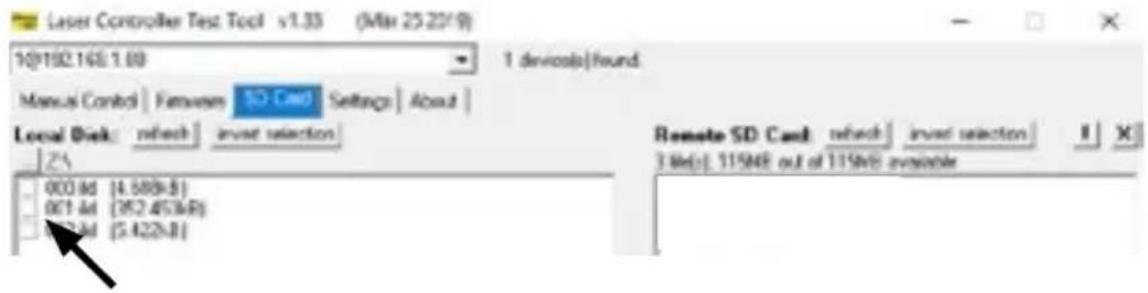
IMPORTANT: Custom laser files have to be stored in *.ild format and must be named with a number from .000.ild' to .255.ild'. Each number represents a DMX value on the respective fader.
To upload *.ild files greater than 6 MB, please use an external card reader. Otherwise the import may cause problems.
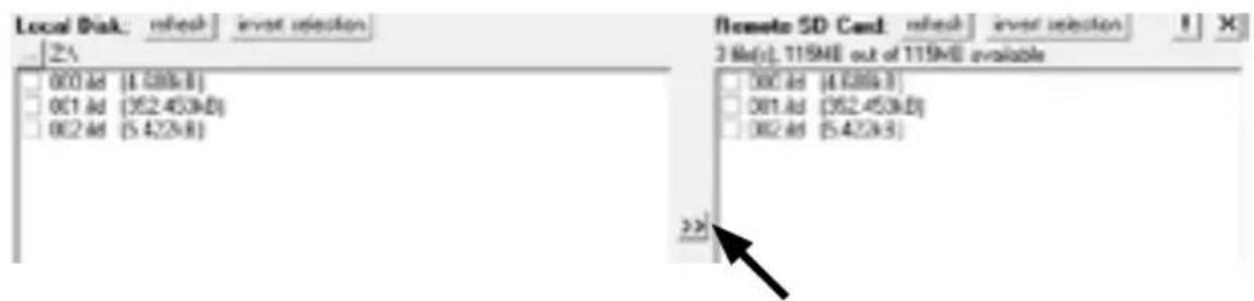
Select the *.ild files to be uploaded from the computer (left side) to the integrated SD card memory (right side).
Click on the button with the two arrows to the right to upload the *.ild files to the integrated SD card. The files are copied and saved now.
Be aware that, due to the optimized data structure on the mainboard, the upload of ILDA files can take a while! (several minutes!)
IMPORTANT: It is not possible to upload any other data than *.ild files to the SD card!
If you want to change the microSD card inside the housing, please contact the Laserworld Service Department.
Due to the huge number of available micro SD cards in the market, it cannot be guaranteed that all cards are compatible with the laser systems mainboard. The use of standard sized (max. 2GB) SD cards instead of high capacity SDHC or XDHC cards is recommended.
It is also possible to copy the existing *.ild files on the SD card to the computer by selecting the files on the right side. Then click on the button with the two arrows to the left.
With the button, invert selection' it is possible to select all files with just one click.
The button with the exclamation mark formats the SD card and thus deletes all existing files.
To delete single files, select the very *.ild file and then click on the button with the ,X' on it (next to the one with the exclamation mark).
In case they got deleted by accident, the standard files card can be downloaded on
https://www.laser-interface.com
b) Stand-Alone Mode / Automatic Mode / Playback Mode
| Dip switch setting | |||||||||
| switch 1 2 3 4 5 | 6 7 8 9 10 | ||||||||
| On (1) / Off (0) | 0 0 0 0 1 | 0 1 0 0 | |||||||
In stand-alone mode the ILDA files on the integrated SD card are triggered automatically. This setting is especially suitable for demo purposes or for fixed laser installations.
The stand alone mode allows for additional advanced features: As standard, the stand alone mode cycles through the ILDA files on the SD cards and plays the consecutively and in a general loop.
If DIP switch 4 is activated too, the stand alone mode only plays one specific ILDA file and just loops this file.
| switch 1 2 3 4 5 | 6 7 8 9 1 | 0 | ||||||||
| On (1) / Off (0) | 0 0 1 0 1 | 0 1 0 0 |
Dip switch 1 can be used to step to the next file (just switch DIP switch 1 to on, then to off again)
Dip switch 2 can be used to step to the previous file (just switch DIP switch 2 to on, then to off again)
c) Demo Mode / Automatic Animation
| switch 1 2 3 4 5 | 678910 | ||||||||
| On (1) / Off (0) | 00010 | 0010 |
In demo mode the ILDA files on the integrated SD card are triggered automatically. The ILDA files are not only played back like in the stand alone mode, but they are also automatically animated by ShowNET's internal intelligence. This creates dynamic animations, even if only static frames are on the SD card.
This setting is especially suitable for demo purposes.
d) Sound-to-Light Mode / Music Mode
| switch 1 2 3 4 5 | 678910 | ||||||||
| On (1) / Off (0) | 00000 | 1010 |
In sound-to-light mode, the ILDA files on the integrated SD card are triggered by the beat of the music. The sensitivity of the microphone can be adjusted with the trim pot at the back side of the device marked „Sens".
e) Master-Slave-Mode: Sound-to-Light
MASTER unit:
| switch 1 2 3 4 5 | 678910 | ||||||||
| On (1) / Off (0) | 00010 | 1010 |
SLAVE units:
| switch 1 2 3 4 5 | 678910 | ||||||||
| On (1) / Off (0) | 00001 | 1100 |
To have the same effects show on all connected units, it is required to have the same pattern sets on all SD cards inside the units.
f) Master-Slave-Mode: Demo Mode
MASTER Unit:
| switch 1 2 3 4 5 | 678910 | ||||||||
| On (1) / Off (0) | 00001 | 0010 |
SLAVE units:
| switch 1 2 3 4 5 | 678910 | ||||||||
| On (1) / Off (0) | 00001 | 1100 |
To have the same effects show on all connected units, it is required to have the same pattern sets on all SD cards inside the units.
g) ArtNet Operation
IMPORTANT: ArtNet operation requires the show laser system to be connected in a DHCP environment (router with integrated switch is recommended). The address handling must be managed through DHCP. For questions on DHCP, please refer to 4.1. DHCP Mode. Only ShowNET interfaces and the ArtNet controller must be used in the same network.
Avoid using other network devices in the same network.
Use the dip switches to assign a certain address like in DMX mode:
| switch 1 2 3 4 5 | 6 7 8 | 9 10 | ||||||||
| Binary DMX channel offset | 1 2 4 | 8 16 | 32 64 | 128 | 2 | 56 Switch 1 | 0 has | to be ON (up) | for ArtNet operation | |
To activate ArtNet trigger, open the admin tool and navigate to the tab ,Settings'. Then change the ,Data source for internal DMX effects' to ,ArtNet input' as seen in the picture below:
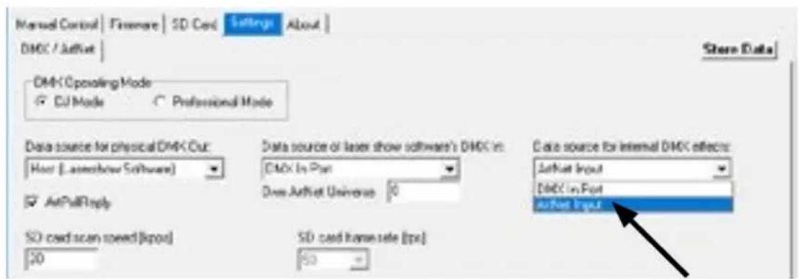
Click on, Store Data' to save the changes. Click on, OK' twice and wait until another window opens that asks to restart the ILDA interface. To do so, switch the laser system off and on again.
See the details on DMX Mode below for more information:
h) DMX Modes
| switch 1 2 3 4 5 | 6 7 8 | 9 10 | ||||||||
| Binary DMX channel offset | 1 2 4 | 8 16 | 32 64 | 128 | 2 | 56 Switch 1 | 0 has to be ON (up) | for DMX mode | ||
There are two DMX / ArtNet configuration modes:
(1) DJ Mode & (2) Professional Mode.
The DJ mode is more basic and comes with some pre-configured automations. It is suitable for most users.
The Professional mode comes with some advanced features and requires deper knowledge of DMX / ArtNet to be handled properly.
DJ mode is the standard option. To use the Professional mode, open the admin tool and navigate to the tab ,Settings'.
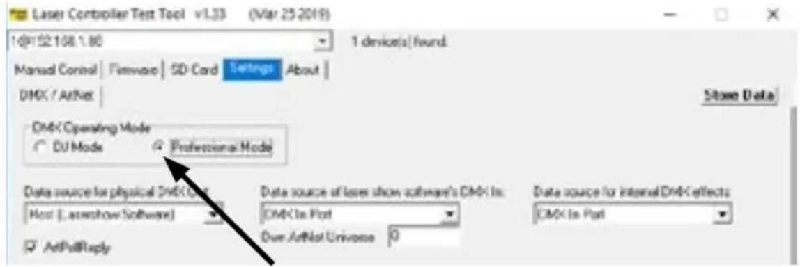
Change the option.
Click on, Store Data' to save your changes. Click on, OK' twice and wait until another window opens that asks to restart the ILDA interface. To do so, switch the laser system off and on again.
(1) DJ Mode
To get laser output, DMX channel 1 needs to have a value greater than 0 (recommended 64 to 192)
| Channel Mode Value Function | |||
| 1 Intensity DJ 0 Laser off | |||
| 1 - 255 Increase | intensity (full intensity = 255) | ||
| 2 Pattern selection DJ 0 B | blackout (000) | ild must not exist | |
| 1 - 255 Display | patterns from SD card: 1 = 001.ILD 2 = 002.ILD ... and so on If no pattern is assigned to a number = blackout | ||
| 1 - 255 Display | |||
| standard speed: | 50 fps | ||
| 16 - 255 Ine | asing speed from 0 fps to 100 fps | ||
| 3 Pattern speed (Framerate) | DJ 0 - 15 St | standard speed: | |
| 16 - 255 Ine | asing speed from 0 fps to 100 fps | ||
| 4 Size DJ 0 - 127 Decreasing size X + Y-axis | |||
| 128 - 191 Decreasing size X-axis | |||
| 192 - 255 Decreasing size Y-axis | |||
| 5 Automatic size | DJ 0 - 63 Full size | ||
| 64 - 127 Changing size automatically X + Y-axis (increasing speed) | |||
| 128 - 191 Changing size automatically X-axis (increasing speed) | |||
| 192 - 255 Changing size automatically Y-axis (increasing speed) | |||
| 6 Rotate | DJ 0 - 192 Manual rotation | ||
| 193 - 224 Automatic rotation anti-clockwise (increasing speed) | |||
| 225 - 255 Automatic rotation clockwise (increasing speed) | |||
| 7 Position X-axis coarse | DJ 0 - 255 = center | ||
| 8 Position X-axis fine DJ 0 - 255 | |||
| 9 Position Y-axis coarse | DJ 0 - 255 = center | ||
| 10 Position Y-axis fine | DJ 0 - 255 | ||
| 11 Color effects | DJ 0 - 15 Show pattern in original colors | ||
| 12 Color effects extended | DJ 0 - 127 S | smooth color fadec | de effect to the re-color effect Value of channel 11 must be >15! |
| 128 - 192 Blocking color effect to the re-color effect Value of channel 11 must be >15! | |||
| 193 - 255 Automatic change of color fade effects (increasing speed) | |||
| 13 Strobe DJ 0 - 15 None | |||
| 16 - 255 Increasing strobe effect | |||
| 14 Operation mode DJ 0 - 19 DMX | 19 DMX | ||
| 20 - 83 Automatic position X & Y-axis | |||
| 84 - 147 Automatic position X-axis | |||
| 148 - 211 Automatic position Y-axis | |||
| 212 - 233 Demonstration mode | |||
| 234 - 255 Sound-to-light | |||
| 15 Scan speed DJ 0 - 31 Default | |||
| 32 - 255 Increasing scan speed (from 5 kpps to 30 kpps) ATTENTION: Make sure not to overload the scanners! If you're unsure about the maximum scan speed, stay with the default setting! | |||
| 16 Safety zone size DJ 0 - 63 Size of horizontal safety zoneSafety zone is the bottom side | |||
| 17 Safety zone intensity DJ 0 | No reduction | ||
| 1 - 128 Decrease brightness up to half brightness | |||
| 129 - 255 Decrease brightness up to blackout | |||
| 18 Blanking | DJ 0 - 192 Manual select how much of the laser pattern shall be blanked | ||
| 193 - 255 Automatic blanking (increasing speed) | |||
| 19 Blankshift | DJ 0 - 192 Manual select the pattern part the blanking of channel 18 shall be applied to | ||
| 193 - 255 Automatic blank shift (increasing speed) | |||
(2) Professional Mode
| Channel Mode Value Function | |||
| 1 Intensity Prof. 0 Laser of | |||
| 1 - 255 Increase intensity (full intensity = 255) | |||
| 2 Pattern selection Prof. 0 | Blackout (000) | ld must not exist | |
| 1 - 255 Disp ay patterns from SD card: 1 = 001.ILD 2 = 002.ILD ... and so on If no pattern is assigned to a number = blackout | |||
| 3 Pattern speed (Framerate) | Prof. 128 Sta | ndard speed 50 fps | |
| 0 - 127 Increasing speed from 0 fps tp 50 fps | |||
| 129 - 255 Increasing speed from 50 fps to 100 fps | |||
| 4 Position X-axis coarse P | of. 0 - 255 From left (0) to right (255); center = 128 | ||
| 5 Position X-axis fine Prof. | 0 - 255 | ||
| 6 Position Y-axis coarse | Prof. | 0 - 255 | From bottom (0) to top (255); center = 128 |
| 7 Position Y-axis fine | Prof. 0 - 255 | ||
| 8 Rotation coarse | Prof. 0 - 255 | Rotate; 0° = 128 | |
| 9 Rotation fine Prof. 0 - 255 | |||
| 10 Size X-axis | Prof. 0 - 255 | From maximum (0) to minimum (255) | |
| 11 Size Y-axis | Prof. | 0 - 255 | From maximum (0) to minimum (255) |
| 12 Inversion | Prof. 0 - 63 | None | |
| 64 - 127 | Invert X-axis | ||
| 128 - 191 Invert Y-axis | |||
| 192 - 255 Invert X + Y-axis | |||
| 13 Color Selection | Prof. | 0 - 15 | Original pattern colors |
| 16 - 207 | Color selection from red (16) through yellow (48), green (80), cyan (112) and blue (144) up to purple (176) with color mixtures in between. | ||
| 208 - 223 White with half intensity for each color channel | |||
| 224 - 239 White with full intensity for each color channel | |||
| 240 - 255 enables channels 14 -16 to select a specific hue | |||
| 14 Red | Prof. 0 - 255 | Increase intensity red Only active if the value of channel 13 is 240 - 255 | |
| 15 Green | Prof. 0 - 255 | Increase intensity green Only active if the value of channel 13 is 240 - 255 | |
| 16 Blue | Prof. 0 - 255 | Increase intensity blue Only active if the value of channel 13 is 240 - 255 | |
| 17 Strobe Prof. 0 - 15 None | |||
| 16 - 255 Increasing strobe effect | |||
| 18 Scan speed Prof. 0 - 15 Default | |||
| 16 - 255 Increasing scan speed (from 5 kpps to 40 kpps) | |||
| 19 Safety zone size Prof. 0 | - 63 Size of horizontal safety zone | ||
| 20 Safety zone intensity Prof. 0 - 255 From max intensity (0) to no intensity (255) | |||
| 21 Color balancing red (for white balance) | Prof. 0 - 255 | From max intensity (0) to no intensity (255) | |
| 22 Color balancing green (for white balance) | Prof. 0 - 255 | From max intensity (0) to no intensity (255) | |
| 23 Color balancing blue (for white balance) | Prof. 0 - 255 | From max intensity (0) to no intensity (255) | |
| IMPORTANT: Channels 24 - 34 are reserved for future features and must not be assigned | |||
Important Note: Operate scanners/galvos only at appropriate speed according to the respective scan angle. Too high scan speed will damage the scanning system.
4. Network Operation
Important:
Only ShowNET interfaces and potentially an ArtNet controller must be used in the same network. Avoid using other network devices in the same network.
Avoiding connectivity issues, Troubleshooting:
- Make sure that no firewall is blocking the network traffic between the computer and the show laser device. The firewall has to be configured to grant network access to the laser show software.
- If the network connection does not work, try to temporarily disable the firewall. If this helps, create a matching rule and re-activate the firewall.
- Whenever the DIP switch settings for the network mode are changed (for example, change static IP address or switch from DHCP to AutoIP mode), the show laser device has to be restarted (switch power off and on).
- The interface has to be connected to a 100Mbit or Gigabit Ethernet LAN. 10Mbit Ethernet is not suitable.
- The use of WIFI (WLAN) is not recommended. This will result in decreased output performance and unsafe operation.
Attention - maximum cable length:
When using ethernet cables with RJ45 connection, always pay attention to the maximum length of the very cable. E.g.:
Cat 5e = .100m
Cat 6 = .50m
Cat 7 = max. 50 m
Cat 8 = max. 30 m
You can use normal network switches to amplify the signal and extend the range!
Without amplification of the signal (e.g. via a switch) it is recommended to use fiber transmission as soon as longer distances are required.
a) DHCP Mode
| Dip switch setting | |||||||||
| switch 1 2 3 4 5 | 6 7 8 9 10 | ||||||||
| On (1) / Off (0) | 0 0 0 0 0 | 0 0 0 0 | |||||||
In this mode, the IP address is provided by a DHCP server. Therefore, a DHCP server has to be available in the network. For example, this could be a cheap 100MBit network router with integrated DHCP server. This option does not work if there is no device in the same network that can distribute and manage network addresses as DHCP! In this case, try AutoIP as connection method (e.g. if the laser is directly connected to the computer)!
b) AutoIP
| switch 1 2 3 4 5 | 678910 | ||||||||
| On (1) / Off (0) | 00001 | 0000 |
In this mode, the IP address is negotiated automatically without the need for a DHCP server. A Windows computer with enabled AutolP is necessary to use this feature. In Windows 7, 8 and 10, AutolP is enabled by default. In Windows XP it has to be enabled manually. Before trying to connect a ShowNET to the computer, make sure that the AutolP feature is enabled. If AutolP is selected, but there is a DHCP server in the network (e.g. in a router), the IP assignment cannot work sometimes. Use DHCP mode in this case.
c) Static IP address
Using a static IP address is the most stable option for network control. The IP address consists of 4 numbers, seperated by a point. The first two number are always 192.168 and cannot be changed. The last two numbers (adr1 and adr2) can be configured with DIP switches. The resulting IP address will be something like
192.168.adr1.adr2
| switch 1 2 3 4 5 | 678910 | ||||||||
| On (1) / Off (0) | 000 - adr2 = 50 | 00 - adr1 = 0 | 1000 | ||||||
| 1000 - adr2 = 51 | 10 - adr1 = 1 | ||||||||
| 0100 - adr2 = 52 | 01 - adr1 = 2 | ||||||||
| 1100 - adr2 = 53 | 11 - adr1 = 254 | ||||||||
| 0010 - adr2 = 54 | |||||||||
| 1010 - adr2 = 55 | |||||||||
| 0110 - adr2 = 56 | |||||||||
| 1110 - adr2 = 57 | |||||||||
| 0001 - adr2 = 58 | |||||||||
| 1001 - adr2 = 59 | |||||||||
| 0101 - adr2 = 60 | |||||||||
| 1101 - adr2 = 61 | |||||||||
| 0011 - adr2 = 62 | |||||||||
| 1011 - adr2 = 63 | |||||||||
| 0111 - adr2 = 64 | |||||||||
| 1111 - adr2 = 65 | |||||||||
The Windows computer needs to have an IP address within the same network subnet.
Example:
| switch 1 2 3 4 5 | 6 7 8 9 1 0 | ||||||||
| On (1) / Off (0) | 1 0 1 0 0 | 1 0 0 0 |
This will assign IP address 192.168.0.61 to the ILDA interface. Assign a different IP address inside the same subnet to the Windows computer, for example 192.168.0.100 (subset = 255.255.255.0)
d) ILDA Streaming
The Laserworld ShowNET interface is capable to act as range extender for ILDA signals by transforming an incoming ILDA signal on the ILDA IN interface to a standard UDP network signal and transferring this signal back to standard ILDA in a receiver unit (obviously an external ShowNET interface is required as sender for this kind of application!). Do NOT send the signal over Wifi, this transmission method is not suitable in a professional environment.
Sender-Receiver configuration for ILDA over LAN, range extender use
The sender uses an IP address range between 192.168.2.70 and 192.168.2.85 and transmits the signal to a receiver that has addresses in the range between 192.168.2.50 and 192.168.2.65. The specific IP addresses need to be set with DIP switches. Make sure there are no other devices in the same network that use the same IP addresses.
| Dip switch setting | ||||||||||
| switch 1 | 2 3 4 5 6 7 8 9 | 10 | ||||||||
| On (1) / Off (0) | 0000 -> IP sender: 192.168.2.70 sends to 192.168.2.50001 -> IP sender: 192.168.2.71 sends to 192.168.2.51001 -> IP sender: 192.168.2.72 sends to 192.168.2.520011 -> IP sender: 192.168.2.73 sends to 192.168.2.530100 -> IP sender: 192.168.2.74 sends to 192.168.2.540101 -> IP sender: 192.168.2.75 sends to 192.168.2.550110 -> IP sender: 192.168.2.76 sends to 192.168.2.560111 -> IP sender: 192.168.2.77 sends to 192.168.2.571000 -> IP sender: 192.168.2.78 sends to 192.168.2.581001 -> IP sender: 192.168.2.79 sends to 192.168.2.591010 -> IP sender: 192.168.2.80 sends to 192.168.2.601011 -> IP sender: 192.168.2.81 sends to 192.168.2.611100 -> IP sender: 192.168.2.82 sends to 192.168.2.621101 -> IP sender: 192.168.2.83 sends to 192.168.2.631110 -> IP sender: 192.168.2.84 sends to 192.168.2.641111 -> IP sender: 192.168.2.85 sends to 192.168.2.65 | sender: 0 receiver: 1 | 0 1 | 1 0 | 0 | |||||
Example:
Sender IP address setting:
| switch 1 2 3 4 5 | 6 7 8 9 1 | 0 | ||||||||
| On (1) / Off (0) | 0 0 1 0 0 | 1 1 0 0 |
This assigns IP address 192.168.2.71 to the Sender.
The corresponding receiver needs this IP address setting:
| switch 1 2 3 4 5 | 6 7 8 9 1 | 0 | ||||||||
| On (1) / Off (0) | 0 0 1 1 | 0 | 1 1 0 0 |
This assigns IP address 192.168.2.51 to the receiver.
The only difference between sender and receiver configuration is dip switch 5, which is 0 for the sender and 1 for the receiver.
10. Operation Instruction - FB4 version
The following operation instructions only apply, if the Diode Series laser has been purchased with built-in Pangolin FB4.
With built-in Pangolin FB4 interface, the Diode Series laser can be controlled over LAN (network cable) or ILDA cable. It is possible either to connect a LAN cable directly from the PC (laptop / tablet) to the laser, or use a network infrastructure (switch, router).
a. Connect the power cable to the device and then to the mains.
b. In order to provide the control signal to the laser device, connect the built-in FB4 interface with the PC or Laptop through network cable (CAT-5 or higher). The built-in FB4 interface can be controlled directly from a PC (laptop / tablet) over Pangolin Quick Show or Pangolin Beyond Software.
c. On software startup, the FB4 interface should be automatically detected and it should show up in the status bar.
d. Connect the interlock adapter to the interlock connector. The show laser doesn't work if the interlock adapter isn't connected to the device.
In case of problems or for further operation instructions of the Pangolin FB4, please see the FB4 operation manual. It can be found here:
https://www.laserworld.com/fb4-manual
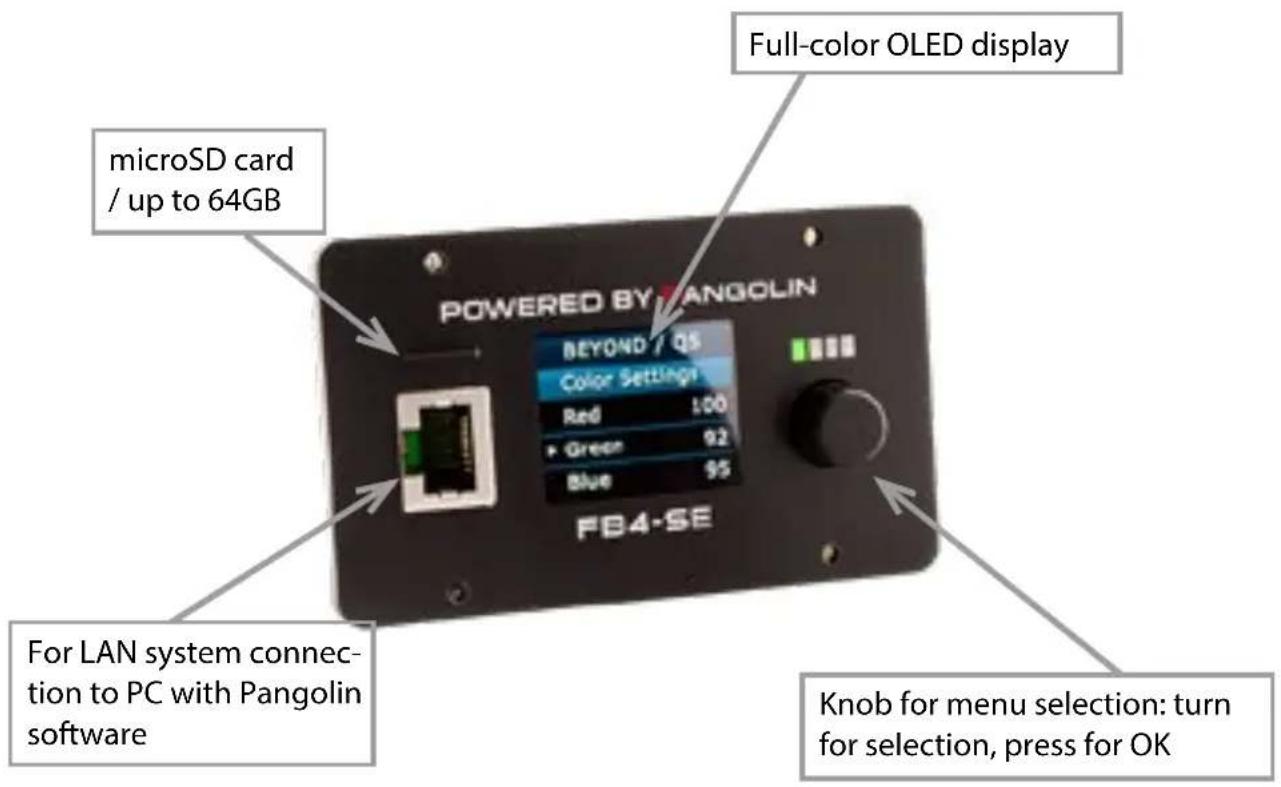
The FB4 interface also has a microSD card slot for using playback features. Please see the FB4 manual for details on how to use this feature.
Final statement
Laserworld products are tested and product packaging is inspected before leaving our warehouse.
Users must to follow the local safety regulations and warnings within this manual and adhere to any regulations within its place of use. Damages through inappropriate use will void any liability or warranty of our products.
Due to continual product developments, please check for the latest update of this product manual at www.laserworld.com. If you do have any further questions, then please contact your dealer/place of purchase or use our contact section on our website.
For service issues, please contact your dealer/place of purchase and ensure only genuine Laserworld spare parts are used in any service repairs.
Errors and Omissions excepted and products are subject to change.
Laserworld (Switzerland) AG
Kreuzlingerstrasse 5
8574 Lengwil
Switzerland
Registered office:
8574 Lengwil / Switzerland
Company number: CH-440.3.020.548-6
Commercial Registry Kanton Thurgau
CEO: Martin Werner
VAT no. (Switzerland): 683 180
UID (Switzerland): CHE-113.954.889
VAT no. (Germany): DE 258030001
WEEE-Reg.-No. (Germany): DE 90759352
www.laserworld.com info@laserworld.com
representative according to EMVG: Ray Technologies GmbH Managing Director: Martin Werner Muhlbachweg 2 83626 Valley / Germany
Inhaltverzeichnis:
(Firmware: 20190520x - Admin tool: v1.33)
https://www.showeditor.com
https://www.showcontroller.com
representative according to EMVG: Ray Technologies GmbH Managing Director: Martin Werner Muhlbachweg 2 83626 Valley / Germany

Table des matieres:
https://www.showeditor.com
https://www.showcontroller.com
d) Mode musical / sound-to-light
| switch 1 2 3 4 5 | 678910 | ||||||||
| On (1) / Off (0) | 00000 | 1010 |
| switch 1 2 3 4 5 | 6 7 8 | 9 10 | ||||||||
| Binary DMX channel offset | 1 2 4 | 8 16 | 32 64 | 128 | 2 | 56 Switch 1 | 0 has | to be ON (up) | for ArtNet operation | |
| switch 1 2 3 4 5 | 6 7 8 | 9 10 | ||||||||
| Binary DMX channel offset | 1 2 4 | 8 16 | 32 64 | 128 | 2 | 56 Switch 1 | 0 has to be CN (up) | for DMX mode | ||
Changez la selection.
representative according to EMVG:
Managing Director: Martin Werner
Mühlbachweg 2
83626 Valley / Germany