
F130D - Fan Air King - Free user manual and instructions
Find the device manual for free F130D Air King in PDF.
| Brand | Air King |
| Model | F130D |
| Product Type | Inline Exhaust Fan |
| Power Supply | 120 V, 60 Hz |
| Adjustable Airflow | 30 to 130 CFM (10 CFM increments) |
| Speed Control | Internal adjustment panel |
| Additional Options | LCD controller (QFAMD), 24V motorized damper, air filter (10x10x2 in) |
| Mounting Type | Surface (wall/ceiling), joist mount, suspension bar mount |
| Recommended Duct | 6 in rigid or insulated flexible |
| Insect Screen | Integrated, removable |
| Intended Use | General residential ventilation |
| Maintenance and Cleaning | Dust with dry cloth or vacuum; do not immerse |
| Safety | Grounding required; lock power before servicing; do not use with electronic speed control |
| Replacement Parts Available | Blower assembly, collars, brackets, access panel, LCD controller, insect screen |
| Warranty | 3 years (parts and labor) |
| Customer Service | Toll-free: (800) 465-7300, Mon-Fri 8am-4pm EST |
Frequently Asked Questions - F130D Air King
User questions about F130D Air King
0 question about this device. Answer the ones you know or ask your own.
Ask a new question about this device
Download the instructions for your Fan in PDF format for free! Find your manual F130D - Air King and take your electronic device back in hand. On this page are published all the documents necessary for the use of your device. F130D by Air King.
USER MANUAL F130D Air King
IMPORTANT INSTRUCTIONS - OPERATING MANUAL
F130D, QFAMD

Inline Fan

READ AND SAVE THESE INSTRUCTIONS
READ CAREFULLY BEFORE ATTEMPTING TO ASSEMBLE, INSTALL, OPERATE OR MAINTAIN THE PRODUCT DESCRIBED. PROTECT YOURSELF AND OTHERS BY OBSERVING ALL SAFETY INFORMATION. FAILURE TO COMPLY WITH INSTRUCTIONS COULD RESULT IN PERSONAL INJURY AND/OR PROPERTY DAMAGE!

RETAIN INSTRUCTIONS FOR FUTURE REFERENCE.
GENERAL SAFETY INFORMATION
When using electrical appliances, basic precautions should always be followed to reduce the risk of fire, electric shock and injury to person, including the following:
WARNING: TO REDUCE THE RISK OF FIRE, ELECTRIC SHOCK AND INJURY TO PERSON, OBSERVE THE FOLLOWING:
a) Use this unit only in the manner intended by the manufacturer. If you have questions, contact the manufacturer.
b) Before servicing or cleaning the unit, switch power off at service panel and lock the service disconnecting means to prevent power from being switched on accidentally. When the service disconnecting means cannot be locked, securely fasten a prominent warning device, such as a tag, to the service panel.

WARNING: TO REDUCE THE RISK OF FIRE, ELECTRIC SHOCK AND INJURY TO PERSON, OBSERVE THE FOLLOWING:
a) Installation work and electrical wiring must be done by qualified person(s) in accordance with all applicable codes and standards, including fire-related construction.
b) Sufficient air is needed for proper combustion and exhausting of gases through the flue (chimney) of fuel burning equipment to prevent back drafting. Follow the heating equipment manufacturer's guideline and safety standards such as those published by the National Fire Protection Association (NFPA) and the American Society for Heating, Refrigeration, and Air Conditioning Engineers (ASHRAE), and the local code authorities.
c) When cutting or drilling into wall or ceiling, do not damage electrical wiring and other hidden utilities.

CAUTION: FOR GENERAL VENTILATING USE ONLY. DO NOT USE TO EXHAUST HAZARDOUS OR EXPLOSIVE MATERIALS AND VAPORS.
d) This unit must be grounded.
e) To avoid motor bearing damage and noisy and/or unbalanced impellers, keep drywall spray, construction dust, etc. off power unit.
f) Read all instructions before installing or using fan.
g) For residential installations only.
h) Must use suitable weather hood with insect screen to protect air intake.


WARNING: TO REDUCE THE RISK OF FIRE, ELECTRIC SHOCK, DO NOT USE THIS FAN WITH ANY SOLID-STATE SPEED CONTROL DEVICE.

WARNING: DO NOT USE IN KITCHENS.

WARNING: THE DUCTING FROM THIS FAN TO THE OUTSIDE OF THE BUILDING HAS A STRONG EFFECT ON THE FLOW, NOISE AND ENERGY USE OF THE FAN. USE THE BEST, STRAIGHTEST DUCT ROUTING POSSIBLE FOR BEST FORMANCE, AND AVOID INSTALLING THE FAN WITH SMALLER THAN RECOMMENDED. INSULATION AROUND THE DUCTS REDUCE ENERGY LOSS AND INHIBIT MOLD GROWTH. FANS LED WITH EXISTING DUCTS MAY NOT ACHIEVE THEIR FAIRFLOW.
SAVE THESE INSTRUCTIONS
INSTALLATION INSTRUCTIONS
CAUTION: MAKE SURE POWER IS SWITCHED OFF AT SERVICE PANEL BEFORE STARTING INSTALLATION.
SECTION 1
Preparing the Fan
- Unpack fan from the carton and confirm that all pieces are present. In addition to the fan you should have:
2 - Collar Assembly (attached) 2 - Mounting Brackets (attached)
1 - Controller (attached) (QFAMD Only) 1 - Instruction/Safety Sheet - Choose the location for your fan. To ensure the best air and sound performance, it is recommended that the length of ducting and the number of elbows be kept to a minimum, the radius of each elbow be as large as possible for the installation, and that insulated hard ducting be used. This fan will require at least 12" of clearance in the ceiling or wall. The fan mounts using the provided mounting brackets or can be surface mounted to a wall or ceiling.
NOTE: The fan must be installed into a location that can be easily accessed once installed.
- No additional vibration deadening materials are needed for this fan.
SECTION 2
Mounting the Fan
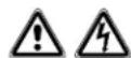
- Confirm the fan is positioned so the air flow is in the correct direction.
2a. Surface Mounting: Locate at least one stud or joist. Place the fan in position so that the mounting bracket is centered on the stud or joist and make the location for the four (4) holes. Remove the fan and install properly rated wall/ceiling anchors for the holes that do not go directly into a joist or stud. Position fan in place and secure with screws (not included) (Figure 1).
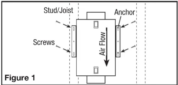
2b. Mounting to a Joist: Install two - 2 x 4 headers (not included) between the joists. Position the fan housing on top of the headers and secure the mounting brackets with screws (not included) to the header (Figure 2).
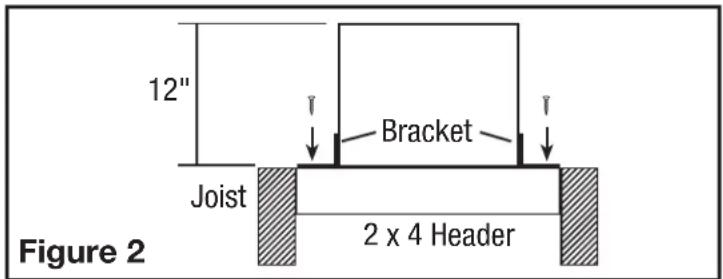
2c. Hanging Bar Mounting: Lift unit up onto the threaded rods and secure in place using appropriate hardware (not included) (Figure 3).
SECTION 3
Ducting
NOTE: 6^th OR LARGER RIGID DUCT IS RECOMMENDED FOR BEST PERFORMANCE.

CAUTION: ALL DUCTING MUST COMPLY WITH LOCAL AND NATIONAL BUILDING CODES.
NOTE: The ducting from this fan to the outside of the building has a strong effect on the air flow, noise and energy use of the fan. Use the shortest, straightest duct routing possible for best performance, and avoid installing the fan with smaller ducts than recommended. Insulation around the ducts can reduce energy loss and inhibit mold growth. Fans installed with existing ducts may not achieve their rated air flow.

WARNING: MAKE SURE THE FRESH AIR INTAKE PORT COMPLIES WITH ALL LOCAL AND NATIONAL CODES AND IS LOCATED AT LEAST 6 FEET AWAY FROM SOURCES OF CONTAMINATION SUCH AS BUT NOT LIMITED TO: DRYER, OR CENTRAL VACUUM EXHAUSTS, GAS APPLIANCES SUCH AS BBQ GRILLS, OR BINS OR OTHER EXHAUST PORTS.
NOTE: To ensure quiet operation of in-line and remote fans, each fan shall be installed using sound attenuation techniques appropriate for the installation. This can typically be achieved by installing insulated flexible ducting between the exhaust or supply grille(s) and the fan.
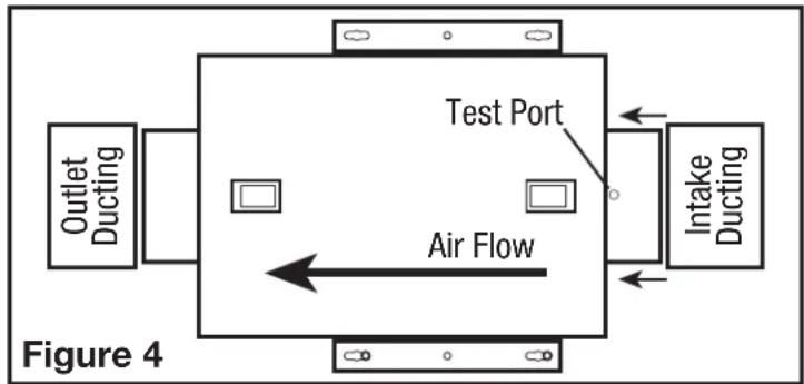
- Connect the ducting to the fan's duct collar (Figure 4). Seal ducting to housing with appropriately rated tape. Use screws or suitable clamps to secure in place. Make sure the fresh air intake is connected to a properly installed intake port that is a suitable weather hood with insect screen to protect air intake. It is recommended that low restriction termination fittings be used.
- Ensure duct joints and exterior penetrations are sealed with caulk or other similar material to create an air-tight path to minimize building heat loss or gain and to reduce the potential for condensation. Place/wrap insulation around duct and/or fan in order to minimize possible condensation buildup within the duct, as well as building heat loss or gain.
NOTE: At the base of the duct adapter, there is a small diameter test port hole covered with a plastic cap. Make sure the test port is not covered up with the ducting so that it can be accessed for pitot tube testing. To access the port, remove the port cover and insert tube.
SECTION 4
Wiring
CAUTION: MAKE SURE POWER IS SWITCHED OFF AT SERVICE PANEL BEFORE STARTING INSTALLATION.
CAUTION: ALL ELECTRICAL CONNECTIONS MUST BE MADE IN ACCORDANCE WITH LOCAL CODES, ORDINANCES, OR NATIONAL ELECTRICAL CODE. IF YOU ARE UNFAMILiar WITH METHODS OF INSTALLING ELECTRICAL WIRING, SECURE THE SERVICES OF A QUALIFIED ELECTRICIAN.
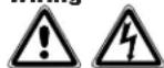
NOTE: This unit includes a side access panel for wiring that does not require the removal of the fan's blower assembly.
- Remove the wire compartment cover screw and place cover in a secure place (Figure 5).
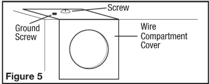
- Pull the loose black, white and green wires out from the wire compartment (additional wires will be present). Install an approved electrical connector to the wire compartment cover (not included). Run a black (hot), white (neutral), and a green or bare ground wire from the supply through the electrical connector. Connect all wires from the supply to their corresponding wires within the wire compartment (Figure 6). Use approved methods for all connections.
- Carefully tuck wires back inside wire compartment and replace wire compartment cover securing with the screw that was removed earlier.
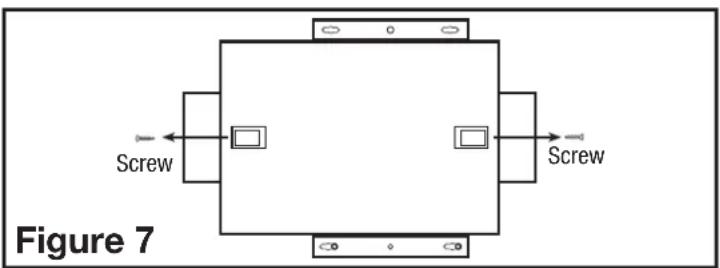
SECTION 5 Setting the Spee
- Remove the screws securing the access panel cover in place and open the cover to gain access. Locate the speed control panel inside the unit (Figure 7).
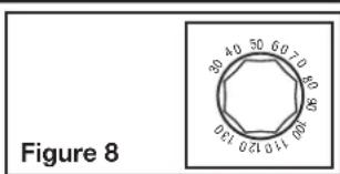
- Determine the CFM required. The unit can be set from 30 CFM to 130 CFM in increments of 10 CFM (Figure 8).
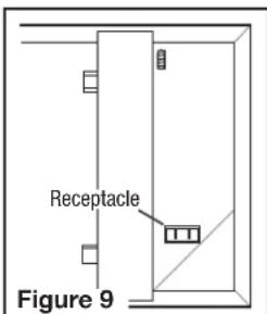
SECTION 6 Motorized Damper
An optional motorized damper can be connected to the unit. The damper is connect via a 24V transformer that plugs into the receptacle in the unit (Figure 9).
NOTE: Make sure to reference the instructions included with the motorized damper before installing or operating.
Operation
- When installed the outlet will be energized anytime the unit is running. This will in turn open the damper. When the unit stops running, the damper will close.
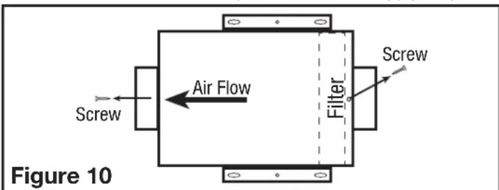
SECTION 7 Optional Air Filter
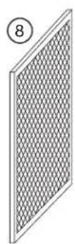
An air filter (available separately) can be added to this unit to provide additional filtration of the intake air. The unit will accept a 10^ × 10^ × 2^ filter. To install:
NOTE: Adding an air filter will decrease the airflow of the unit. You will need to increase the CFM selected in SECTION 5 to account for the decreased air flow. Filters must be changed regularly. Refer to the filter manufacturer's recommendations to determine how often the filter should be changed.
- Remove the screws securing the access panel cover in place and open the cover to gain access to the controls and filter area.
- Ensure the filter is facing the correct way and slide the filter into the slot in the housing. Make sure the filter is seated all the way to the bottom of the housing (Figure 10).
- Close the access panel and reinstall the screw holding the access panel in place.
SECTION 8 Completing the Installation
NOTE: When fan is mounted inline and no penetration is made into unconditioned spaces, there is no need to use a sealant appropriate for contact with the building materials present and for the temperature requirements of the installation to prevent air leakage from unconditioned spaces. Additional material (backing rod, ceiling material) are also not required.
NOTE: This unit is equipped with a wire mesh insect screen. Confirm that the screen is installed on the inside of the unit on the inlet ducting side.
- If the screen is not in place, insert the screen into the tab at the base of the unit (make sure the wider side of the screen is running side to side inside the unit) (Figure 11).
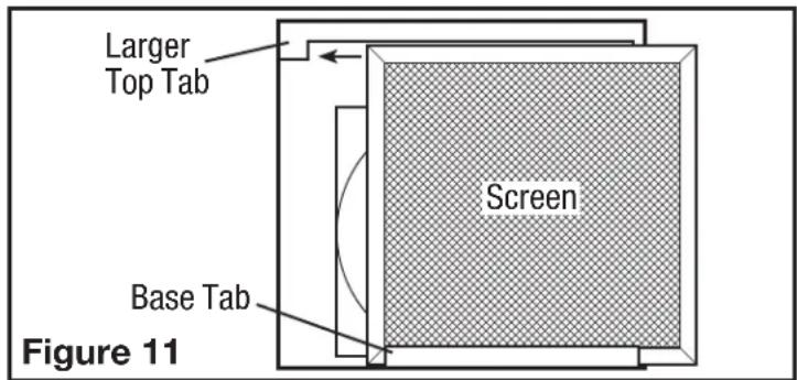
- Slide the screen to the side with the larger top tab making sure the screen fits behind the tab (Figure 11).
- Slide the screen back over towards the smaller top tab making sure the screen fits behind the tab (Figure 12).
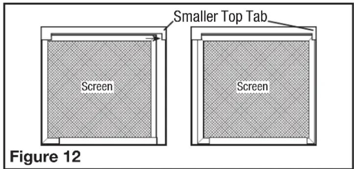
- Confirm that the screen is being held in place by both top tabs (Figure 12).
- Close the access panel and reinstall the screws holding the access panel in place.
- Restore power and test your installation.
SECTION 9 (QFAMD only) Using the Controller
- On Mode: Fan will run continuously when the ON button () is pressed. If ambient temperature is lower than 34^ (2^) , the fan will stop and initiate Sampling Mode. Sampling Mode Cycle: stop 15 mins; run for 5 minutes to determine current air temperature. During Sampling Cycle, if the temperature is in the accessory heater (optional) control range, the heater will turn on (if it has been installed). The fan will return to continuous ventilation once ambient temperature rises above 34^ (2^) .
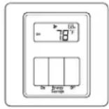
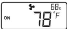
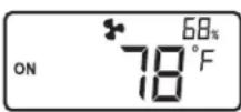
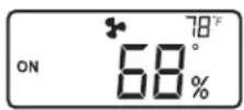
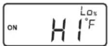
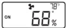
- Energy Savings Mode: To enter the Energy Savings mode, press the Energy Savings button (until appears on the left side of the display. Energy Savings mode engages the settings configured in SECTION 10. When the unit is on, the display will show the current conditions (temperature and humidity level) as well as if it is in Energy Savings mode or not. Other icons/information that may be on the display include:
Fan icon appears when the fan is on.
"HI°F" appears if the intake temperature is above 150^ (65^)
^ Lo^ F appears if the intake temperature is below 15^ (-10^)
Lo% appears if the intake humidity is below 10%.
- Optional Heater Unit: An optional heater unit is available for climates that the air coming into the unit falls below 54^ (12^) . To install the unit, follow the directions that are included with that unit. The display will show a thermometer icon with either a "1" (1) or "1 2" (2) when the temperature range is at a level where the heating element would come on if present. Stage 1 - "1" turns on when the intake air temperature is between 39^ (4^) and 54^ (12^) . Stages 1 and 2 "1 2" turn on when the intake air temperature is between 33^ (0^) and 39^ (4^) .
SECTION 10 (QFAMD only)
Setting the Controller (Energy Savings Mode Only)
If the main access panel has not already been removed, remove the screws securing the access panel cover in place and open the cover to gain access. Locate the control cover inside the unit. To access the control panel, pull the control cover down from the top (Figure 13).
Control Cover Control Panel
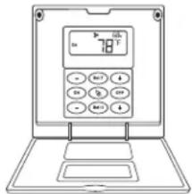
Figure 13
In the normal operation display, press and hold the "SetT" button for 5 seconds to switch the temperature between Fahrenheit and Celsius units.
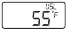
After pressing the "SetT" button, the display shows the setting value of the upper limit temperature. The following figure is displayed. Press the "+" or "+" buttons on both sides to adjust the upper limit temperature value.
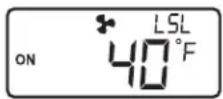
Pressing the "SetT" button again, the lower limit temperature setting value is displayed on the display, as shown below. Press the " - " or "+" buttons on both sides to adjust the content of the lower limit temperature value.
After the setting is completed, press the "SetT" button to return to normal display.
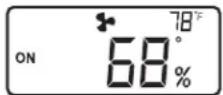
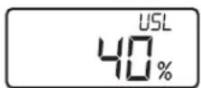
Press the "SetH" button. The display shows the setting value of the upper limit humidity. The following figure is displayed. Press the "+" or "+" buttons on both sides to adjust the upper limit humidity value.
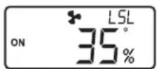
After pressing the "SetH" button again, the lower limit humidity setting value is displayed on the display, as shown on the right. Press the "+" or "+" buttons on both sides to adjust the lower limit humidity value.
After the setting is completed, press the "SetH" button to return to normal display. In the normal operation display, press and hold the "SetH" button for 5 seconds to switch the display position of temperature and humidity.
When the temperature is higher than 150^ (65^) , the display will show "HiF". When the temperature is lower than 15^ (-10^) , the display will show "LoF"; when the humidity is lower than 10% , the display will show "Lo%.
When the detection temperature sensor and humidity sensor are abnormal, "---" is displayed.

To restore the factory setting, make sure the unit is in the "OFF" setting. Hold the Energy Savings Button for approximately 5 seconds.
- Default temperature setpoint range: 40^ (Low) - 90°F (High).
Low temperature setpoint adjustment range: 32^ - 55^ (0^ - 10^) .
High temperature setpoint adjustment range: 65^ - 95^ (18^ - 35^) - Default humidity setpoint range: 30% (Low) - 65% (High). Low humidity setpoint adjustment range: 10% - 50% . High humidity setpoint adjustment range: 55% - 80% .
SECTION 11
Use and Care
CAUTION: MAKE SURE POWER IS SWITCHED OFF AT SERVICE PANEL BEFORE SERVICING THE UNIT.
- Cleaning the Fan Assembly: Wipe all parts with a dry cloth or gently vacuum the fan. NEVER IMMERSE ELECTRICAL PARTS IN WATER.
NOTE: If you notice a large amount of insects and debris in the insect filter, this could be a sign that the intake weather hood (roof cap or wall cap) might be compromised and need repair or replacing.
- Optional Air Filter: If an optional air filter is installed, it should be checked every month and replaced at least once every 3 months. Reverse the instructions in the SECTION 7 of these instructions to remove filter.
CALIFORNIA RESIDENTS ONLY:

WARNING: THIS PRODUCT CAN EXPOSE YOU TO A CHEMICAL [OR CHEMICALS] KNOWN TO THE STATE OF CALIFORNIA TO CAUSE CANCER.
WARNING: THIS PRODUCT CAN EXPOSE YOU TO A CHEMICAL [OR CHEMICALS] KNOWN TO THE STATE OF CALIFORNIA TO CAUSE REPRODUCTIVE TOXICITY.


Troubleshooting Guide
Trouble Probable Cause Suggested Remedy
| 1. Fan does not operate. | 1a. Control setting. | 1a. Check temperature and humidity level settings. If the intake air is not within the preset range, the fan will not turn on. Either adjust the settings or wait for the intake air temperature and/or humidity to change. |
| 1b. A fuse may be blown or a circuit tripped. 1b. Replace fuse or reset circuit breaker. | ||
| 1c. Wiring is not connected properly. 1c. Turn off power to unit. Check that all lights are connected. | ||
| 1d. Motor has stopped operating. 1d. Replace motor. | ||
| 2. Fan is operating, but air moves slower than normal. | 2a. Obstruction in the ducting. | 2a. Check for any obstructions in the ducting. The most common are bird nests in the roof cap or wall cap where the fan intakes from the outside. |
| 2b. Filter is clogged. 2b. Change air filter (if equipped). | ||
| 2b. Change/clear bug filter. | ||
| 3. Fan is operating louder than normal. | 3a. Motor is loose. | 3a. Turn off power to unit and check that all screws are fully tightened. Restore power to unit. |
| 3b. Fan blade is hitting housing of unit. | 3b. Call your dealer for service. | |
LIMITED WARRANTY
WHAT THIS WARRANTY COVERS: This product is warranted against defects in workmanship and/or materials.
HOW LONG THIS WARRANTY LASTS: This warranty extends only to the original purchaser of the product and lasts for three (3) years from the date of original purchase or until the original purchaser of the product sells or transfers the product, whichever first occurs.
WHAT AIR KING WILL DO: During the warranty period, Air King will, at its sole option, repair or replace any part or parts that prove to be defective or replace the whole product with the same or comparable model.
WHAT THIS WARRANTY DOES NOT COVER: This warranty does not apply if the product was damaged or failed because of accident, improper handling or operation, shipping damage, abuse, misuse, unauthorized repairs made or attempted. This warranty does not cover shipping costs for the return of products to Air King for repair or replacement. Air King will pay return shipping charges from Air King following warranty repairs or replacement
ANY AND ALL WARRANTY, EXPISED OR IMPLIED (INCLUDING, WITHOUT LIMITATION, ANY IMPLIED WARRANTY OF MERCHANTABILITY), LAST THREE YEARS FROM THE DATE OF ORIGINAL PURCHASE OR UNTIL THE ORIGINAL PURCHASER OF THE PRODUCT Sells OR TRANSFERS THE PRODUCT, WHICHEVER FIRST OCCURS AND IN NO EVENT SHALL AIR KING'S LIABILITY UNDER ANY EXPRESS OR IMPLIED WARRANTY INCLUDE (I) INCIDENTAL OR CONSEQUENTIAL DAMAGES FROM ANY CAUSE WHATSOEVER, OR (II) REPLACEMENT OR REPAIR OF ANY HOUSE FUSES, CIRCUIT BREAKERS OR RECEPTACLES. NOTWITHSTANDING ANYTHING TO THE CONTRARY, IN NO EVENT SHALL AIR KING'S LIABILITY UNDER ANY EXPRESS OR IMPLIED WARRANTY EXCEED THE PURCHASE PRICE OF THE PRODUCT AND ANY SUCH LIABILITY SHALL TERMINATE UPON THE EXPIRATION OF THE WARRANTY PERIOD.
Some states and provinces do not allow limitations on how long an implied warranty lasts, or the exclusion or limitation of incidental or consequential damages, so these exclusions or limitations may not apply to you. This warranty gives you specific legal rights. You may also have other rights which vary from state to state and province to province. Proof of purchase is required before a warranty claim will be accepted.
CUSTOMER SERVICE:
Toll-Free (800) 465-7300
Our Customer Service team is available to assist you with product questions, service center locations, and replacement parts. They can be reached Monday through Friday, 8am-4pm Eastern. Please have your model number available, as well as the type and style (located on the label inside of your product).
Please do not return product to place of purchase.
www.airkinglimited.com
PARTS FOR DISCONTINUED, OBSOLETE AND CERTAIN OTHER PRODUCTS MAY NOT BE AVAILABLE. DUE TO SAFETY REASONS, MANY ELECTRONIC COMPONENTS AND MOST HEATER COMPONENTS ARE NOT AVAILABLE TO CONSUMERS FOR INSTALLATION OR REPLACEMENT.
Installer:
Place of Purchase:
Installation Date:
Model Number:
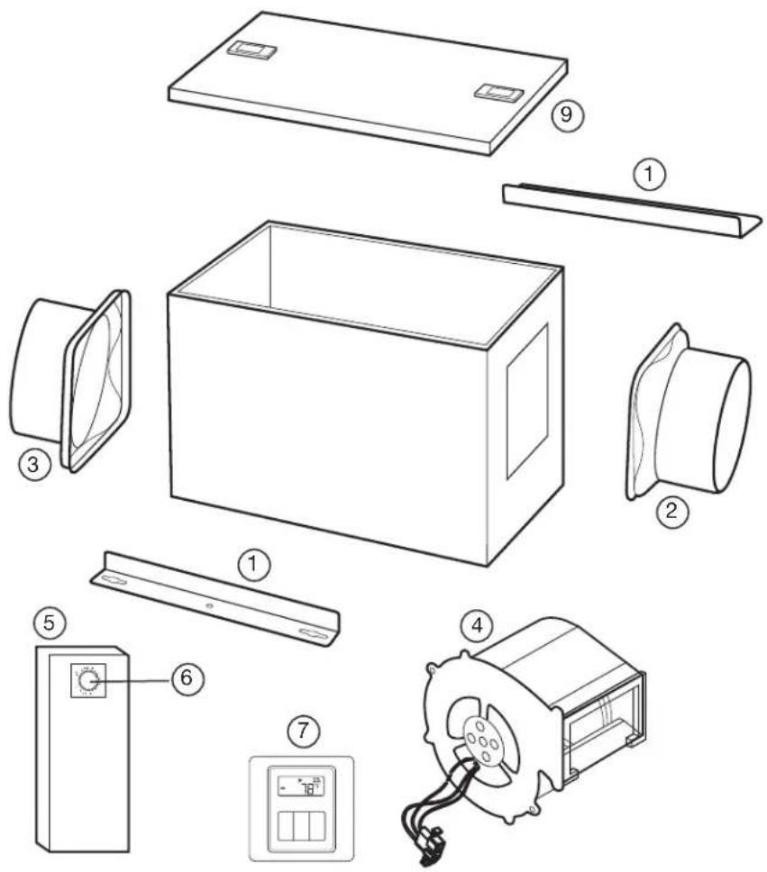
REPLACEMENT PARTS DIAGRAM
| #Q | Description Replacement Part # | |
| 1 2 | Mounting Brackets 5S1650001 | |
| 2 1 | 6" Metal Collar (Intake) 5S1650002 | |
| 3 1 | 6" Metal Collar (Outlet) 5S1650003 | |
| 4 1 | Blower Assembly 5S1650102 | |
| 5 1 | Wire Compartment Assembly 5S1650101 | |
| 6 2 | Adjustment Knobs 5S1299802 | |
| 7 1 | LCD Controller (QFAMD) 5S1650043 | |
| 8 1 | Insect Screen | S1650005 |
| 9 1 | Access Panel | S1650044 |
INSTRUCTIONS IMPORTANTES - MANUEL D'OPÉRATION
QFAMD,F130D

After pressing the "SetH" button again, the lower limit humidity setting value is displayed on the display, as shown on the right. Press the "...ou "+" buttons on both sides to adjust the lower limit humidity value.


- IMPORTANT INSTRUCTIONS - OPERATING MANUAL
- READ AND SAVE THESE INSTRUCTIONS
- RETAIN INSTRUCTIONS FOR FUTURE REFERENCE.
- GENERAL SAFETY INFORMATION
- SAVE THESE INSTRUCTIONS
- INSTALLATION INSTRUCTIONS
- SECTION 1
- Preparing the Fan
- SECTION 2
- Mounting the Fan
- SECTION 3
- Ducting
- SECTION 4
- Wiring
- SECTION 5 Setting the Spee
- SECTION 6 Motorized Damper
- Operation
- SECTION 7 Optional Air Filter
- SECTION 8 Completing the Installation
- SECTION 9 (QFAMD only) Using the Controller
- SECTION 10 (QFAMD only)
- Setting the Controller (Energy Savings Mode Only)
- SECTION 11
- Use and Care
- CAUTION: MAKE SURE POWER IS SWITCHED OFF AT SERVICE PANEL BEFORE SERVICING THE UNIT.
- CALIFORNIA RESIDENTS ONLY:
- Troubleshooting Guide
- LIMITED WARRANTY
- CUSTOMER SERVICE:
- REPLACEMENT PARTS DIAGRAM
- INSTRUCTIONS IMPORTANTES - MANUEL D'OPÉRATION
Brand : Air King
Model : F130D
Category : Fan