
99533 - Fan Air King - Free user manual and instructions
Find the device manual for free 99533 Air King in PDF.


| Product Type | Floor Fan |
| Model Number | 99533 |
| Brand | Air King |
| Blade Diameter | 20 inches (approx.) |
| Dimensions (H x W x D) | 24 x 24 x 6 inches |
| Weight | 7.5 lbs |
| Power Supply | 120V AC, 60Hz |
| Power Consumption | 60 Watts |
| Number of Speed Settings | 3 |
| Oscillation | Yes, 90° horizontal |
| Control Type | Manual rotary switch |
| Grill Material | Steel with powder coating |
| Blade Material | Aluminum |
| Safety Features | Overheat protection, stable base |
| Cleaning Instructions | Wipe with damp cloth; do not immerse |
| Filter | None |
| Assembly Required | Minimal (attach base and front grill) |
| Warranty | 1 year limited |
| Certifications | ETL Listed |
Frequently Asked Questions - 99533 Air King
User questions about 99533 Air King
0 question about this device. Answer the ones you know or ask your own.
Ask a new question about this device
Download the instructions for your Fan in PDF format for free! Find your manual 99533 - Air King and take your electronic device back in hand. On this page are published all the documents necessary for the use of your device. 99533 by Air King.
USER MANUAL 99533 Air King
PLEASE READ AND SAVE THESE INSTRUCTIONS. Read carefully before attempting to assemble, install, operate or maintain the product described. Protect yourself and others by observing all safety information. Failure to comply with instructions could result in personal injury and/or property damage! Retain instructions for future reference.
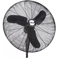
24" & 30" Quiet Design Oscillating Pedestal Fan
Description
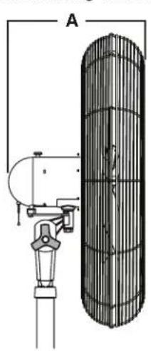
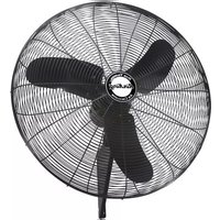
Designed for cooling workers in factories, warehouses, manufacturing facilities and garages where humid and demanding conditions exist. All circulator heads have high efficiency corrosion resistant propellers with steel blades. Circulator heads utilize a vertical tilt/locking adjustment for directional flow. Wire guards are black power-coated steel and comply with OSHA Standard 1910.212 (1/2" maximum opening). All circulator heads are oscillating that sweep through a 45° or 90° arc.
Unpacking
- Inspect for any damage that may have occurred during transit.
- Shipping damage claim must be filed with carrier.
- Check all bolts, screws, setscrews, etc. for looseness that may have occurred during transit. Retighten as needed.
natural_image
Technical diagram of a cylindrical device with a vertical structure and mechanical arm (no text or symbols)
natural_image
Circular fan or radial structure with evenly spaced segments, no text or symbols visible
Oscillating Dimensions and Specifications
| Model | Dia. | A | B | Volts | Hz | Speeds | Blades | Mounting Accessory |
| 99533 | 24" | 14 1/2" | 26 3/4" | 120 | 60 | 3 | 3 | Pedestal |
| 99532 | 30" | 14 1/2" | 33 3/8" | 120 | 60 | 3 | 3 | Pedestal |
| Model | Prop. Dia. | Motor RPM | HP | High | CFM Med | Low | Air Velocity @ 20 Ft. (FPM) | Sones @ 0.000SP | Operating Amps | Full Load Amps |
| 99533 | 24" | 1025/880/480 | 1/4 | 5030 | 4320 | 2280 | 500/350/220 | 7.7/5.7/1.8 | 2.3/1.6/0.6 | 3.5 |
| 99532 | 30" | 1010/860/530 | 1/4 | 7450 | 6090 | 3450 | 700/520/300 | 6.7/5.4/2.0 | 2.3/1.6/0.6 | 3.7 |
24" & 30" Quiet Design Oscillating Pedestal Fan
GENERAL SAFETY INFORMATION When using electrical appliances, basic precautions should always be followed to reduce the risk of fire, electric shock and injury to person, including the following:
- Read all instructions before using Fan.
- Make certain that the power source conforms to the electrical requirements of the Fan.
- Use this Fan only as described in this manual. Any other use not recommended by the manufacturer may cause fire, electrical shock, or injury to persons.
- To reduce the risk of personal injury and electric shock, the Fan should not be played with or placed where small children can reach it.
- Unplug power cord before servicing, or moving the Fan.
WARNING: DO NOT DEPEND UPON THE ON-OFF SWITCH AS THE SOLE MEANS OF DISCONNECTING POWER WHEN INSTALLING OR SERVICING THE FAN. ALWAYS UNPLUG THE POWER CORD.
- This Fan must NOT be used in potentially dangerous locations such as flammable, explosive, chemical-laden or wet atmospheres.
- DO NOT use Fan in or near a window. Rain may create an electrical hazard.
- Completely reassemble Fan, according to instructions, before reconnecting to power supply.
- The power cord is equipped with a three-prong grounded plug that should be inserted into a matching receptacle. Under no circumstances should the grounding prong be cut off the plug. Where a two-prong wall receptacle is encountered, it must be replaced with a properly grounded three-prong receptacle installed in accordance with the National Electrical Code (NEC) and all applicable local codes and ordinances. This work must be done only by a qualified electrician, using copper wire only.
WARNING: USE OF A THREE-PRONG TO TWO-PRONG ADAPTER IS NOT RECOMMENDED. IMPROPER CONNECTION MAY CREATE THE
RISK OF ELECTRICAL SHOCK. USE OF SUCH ADAPTERS IS NOT PERMITTED IN CANADA.
- Where possible, avoid the use of extension cords. If they must be used, minimize the risk of overheating by ensuring that they are UL listed. Never use a single extension cord to operate more than one Fan. Do not plug Fan into any other cord connected device, such as a power strip, cord reel, surge protector, multiple outlet adapters or outlet-type air fresheners. The use of such devices may create a fire hazard.
- Do not operate any Fan with a damaged cord or plug or after the Fan malfunctions, has been dropped or damaged in any manner. Return Fan to authorized service facility for examination, electrical or mechanical adjustment or repair.
- Do not insert or allow fingers or foreign objects to enter any ventilation or exhaust opening as it may cause an electric shock or fire, or damage the Fan. Do not block or tamper with the Fan in any manner while it is in operation.
- Locate the Power Cord so the Fan or other objects are not resting on it. Do not run Power Cord under carpeting or floor mats. Do not cover Power Cord with runners, or the like. Do not run Power Cord through doorways, windows or areas where cord impingement may occur. Arrange Power Cord away from room traffic and where it will not be tripped over.
- This Fan is not intended for use in wet or damp locations. Never locate a Fan where it may fall into water.
- Do not use Fan outdoors.
- This Fan is not suitable for use in hazardous locations. Please refer to National Electric Code (NEC) Article 500 or applicable state or local codes or standards relating to electrical requirements for Hazardous locations.
THIS FAN DOES NOT MEET THE REQUIREMENTS OF NEC ARTICLE 500 (2008).
WARNING: REDUCE THE RISK OF FIRE OR ELECTRIC SHOCK – DO NOT USE THIS FAN WITH ANY SOLID STATE SPEED CONTROL DEVICES.
CAUTION: BECAUSE OF THE SIZE AND WEIGHT OF THIS FAN, MAKE SURE ALL PARTS ARE COMPLETELY ASSEMBLED ACCORDING TO INSTRUCTIONS. FAILURE TO DO SO COULD RESULT IN FAN COMING APART DURING OPERATION AND/OR PERSONAL INJURY.
COLUMN AND MOTOR ASSEMBLY
Locate Motor Hardware Bag to Assemble Column and Motor Assembly.
- Place flat section on Upper Tube of Column Assembly next to Neck on Motor Assembly. Align the 1/2" diameter hole in the flat section on the Upper Tube of Column Assembly with the 1/2" diameter hole in the Motor Assembly. (Figure 1)
- Insert the 1/2" X 1" Hex Bolt (3/4" head) through the Motor Neck, and the Upper Tube Assembly. Place 1/2" diameter Split Lockwasher then the 1/2" diameter Hex Nut (3/4" head) and tighten fully with a adjustable wrench. (Figure 1)
- From the same side of the Motor Neck, insert one 1/4-20 X 1 5/8" Carriage Bolt through the Arc-Shaped Slot in the Motor Neck and Hole in the Upper Pipe of Column Assembly. (Figure 1)
- Attach pull string to motor speed switch, if desired.
COLUMN/MOTOR TO BASE/ASSEMBLY
- Rest Column and Motor Assembly on floor next to the Base Assembly. Tilt Base Assembly up on end. Pick up lower pipe of Column Assembly and insert into the Mounting Flange. (Figure 2)
- Loosen (2) 3/8-16 X 3/8" Allan Head Bolt in the Mounting Flange. This will allow the Column to settle in the bottom of the Base after setting the Fan upright.
- Tilt entire assembly to the upright position. MAKESUREBOLTSINCOLUMNAND MOTOR ASSEMBLY STEPS ARE TIGHT BEFORE STANDING FAN UPRIGHT.
- Tighten the (2) 3/8-16 X 3/8" Allen Head Bolt in the Mounting Flange.

natural_image
Technical line drawing of a mechanical assembly with a vertical frame and a long rod, labeled as Figure 2 (no text or symbols on the diagram itself)GRILL AND BLADE ASSEMBLY CONTINUED
natural_image
Technical line drawing of a propeller assembly with a side view showing internal structure (no text or symbols)
natural_image
Technical line drawing of a mechanical component with no visible text or symbolsInset A

GRILL AND BLADE ASSEMBLY
Locate remaining parts from Motor Hardware Bag to Assemble Grills and Blade to the Motor.
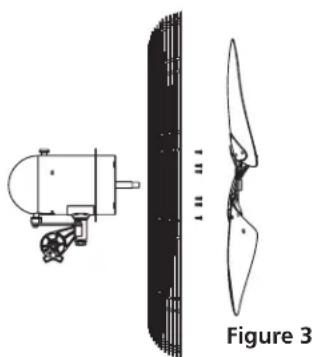
- Install the Rear Grill onto the Motor, lining up the six holes in the grill with the six threaded holes in the motor mounting flange. Install (6) 10-32 X 5/16" Hex Screws through the rear grill into the grill mounting flange. Securely tighten all (6) screws. (Figure 3)
- Push the Fan Blade onto the Motor Shaft, centering the Hub facing away from the motor, until it stops against the shaft (Inset A). Align Square Head Bolt with flat of the motor shaft. TIGHTEN VERY SECURELY WITH AN ADJUSTABLE WRENCH. Failure to securely tighten the Bolt could result in damage to the Fan and/or personal injury.
- Hold the Front Grill so that the name, in the center, is right side up and straight across. Starting at the top: Fasten Front Grill to Rear Grill by sliding the hooked wires on the Front Grill over the outermost ring on the Rear Grill. (Figure 4 / Detail A). The bottom most hooks will require the use of a flathead screwdriver to complete assembly. Stand behind the Fan. Slip the flat of the screwdriver between the Front and Rear Grills, next to one of the unfastened hooks. (Figure 4 / Detail B) Pull screwdriver handle upwards towards the Rear Grill. Slip the Front Grill hook over the Rear Grill outer ring with a push. Repeat procedure with remaining hooks.
CAUTION: DO NOT BEND WIRES ON THE FRONT OR THE REAR GRILLS.
3 5085460New 5/11

natural_image
Technical line drawing of a mechanical device with a curved blade and lever mechanism (no text or symbols)Figure 4

natural_image
Diagram of a curved, segmented structure labeled 'Detail A' (no other text or symbols)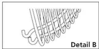
natural_image
Diagram of a coiled spring or rope structure with no text or symbolsOPERATING INSTRUCTIONS
- TO OPERATE: Plug cord into a grounded 120V, 60 Hz outlet. Select desired operating speed with pull cord on the rear of the motor:
First pull: High
Second pull: Medium
Third pull: Low
Fourth pull: OFF
NOTE: THIS FAN IS VERY HEAVY.
Failure to securely hold onto head assembly while adjusting head angle could result in personal injury.
- TO ADJUST HEAD ANGLE: While holding head firmly, loosen knob under motor (turn counterclockwise). Tilt head to desired position FIRMLY retighten knob under motor.
FOR OSCILLATING MODELS:
- OSCILLATION: Push down oscillation knob on motor housing to make fan head move from side to side.
NOTE FOR OSCILLATING MODELS: FAN IS SHIPPED WITH 90° OSCILLATION ANGLE. FOR 45° OSCILLATION ANGLE, CONNECT THE OSCILLATION LINK TO THE INNERMOST HOLE IN THE CAM GEAR. (Inset A)


MAINTENANCE
WARNING: ALWAYS UNPLUG THE CORD BEFORE MOVING OR SERVICING.
WARNING: DO NOT IMMERSE FAN IN WATER!
CLEANING: Use a soft cloth and mild soap solution such as liquid dish washing detergent. Dry all parts completely before reconnecting to power supply.
CLEANING: Use a soft cloth and mild soap solution such as liquid dish washing detergent. Dry all parts completely before reconnecting to power supply.
SERVICING: All other servicing, with the exception of general user maintenance, should be performed by an authorized service representative.
LUBRICATION: Precision motor bearings are sealed at the factory for life and do not require further lubrication.
STORAGE: Store the Fan, with these instructions, in a clean and dry place.
PREVENTATIVE MAINTENANCE:
Occasionally check oscillation link bolts (2) and tighten as necessary.
For Repair Parts, call 1-800-233-0268
Please provide following information:
-Model number
-Serial number (if any)
-Part description and number as shown in parts list

Repair Parts List for 24" & 30" Quiet Design Oscillating Pedestal Fan
| Ref. No. | Description | Part Numbers for Models | ||
| 99533 (24") | 99532 (30") | Qty | ||
| 1 | Blade | 5081015BKB | 5082036BK | 1 |
| 2 | Motor | 02030260 | 02030260 | 1 |
| 3 | Front Grill w/ ornament | 5097030 | 5097145 | 1 |
| 4 | Rear Grill | 5097022BK | 5097012BK | 1 |
| 5 | Column Assembly w/set screw | 5062235A | 5062235A | 1 |
| 6 | Hardware Bag | 05098022 | 05098022 | 1 |
| 7 | Base | 05060055BK | 05060055BK | 1 |
24" & 30" Quiet Design Oscillating Pedestal Fan
LIMITED WARRANTY
WHAT THIS WARRANTY COVERS: This product is warranted against defects in workmanship and/or materials.
HOW LONG THIS WARRANTY LASTS: This warranty extends only to the original purchaser of the product and lasts for one (1) year from the date of original purchase or until the original purchaser of the product sells or transfers the product, whichever first occurs.
WHAT AIR KING WILL DO: During the warranty period, Air King will, at its sole option, repair or replace any part or parts that prove to be defective or replace the whole product with the same or comparable model.
WHAT THIS WARRANTY DOES NOT COVER: This warranty does not apply if the product was damaged or failed because of accident, improper handling or operation, shipping damage, abuse, misuse, unauthorized repairs made or attempted. This warranty does not cover shipping costs for the return of products to Air King for repair or replacement. Air King will pay return shipping charges from Air King following warranty repairs or replacement
ANY AND ALL WARRANTIES, EXPRESSED OR IMPLIED (INCLUDING, WITHOUT LIMITATION, ANY IMPLIED WARRANTY OF MERCHANTABILITY), LAST ONE YEAR FROM THE DATE OF ORIGINAL PURCHASE OR UNTIL THE ORIGINAL PURCHASER OF THE PRODUCT SELLS OR TRANSFERS THE PRODUCT, WHICHEVER FIRST OCCURS AND IN NO EVENT SHALL AIR KING'S LIABILITY UNDER ANY EXPRESS OR IMPLIED WARRANTY INCLUDE (I) INCIDENTAL OR CONSEQUENTIAL DAMAGES FROM ANY CAUSE WHATSOEVER, OR (II) REPLACEMENT OR REPAIR OF ANY HOUSE FUSES, CIRCUIT BREAKERS OR RECEPTACLES. NOTWITHSTANDING ANYTHING TO THE CONTRARY, IN NO EVENT SHALL AIR KING'S LIABILITY UNDER ANY EXPRESS OR IMPLIED WARRANTY EXCEED THE PURCHASE PRICE OF THE PRODUCT AND ANY SUCH LIABILITY SHALL TERMINATE UPON THE EXPIRATION OF THE WARRANTY PERIOD.
Some states and provinces do not allow limitations on how long an implied warranty lasts, or the exclusion or limitation of incidental or consequential damages, so these exclusions or limitations may not apply to you. This warranty gives you specific legal rights. You may also have other rights which vary from state to state and province to province. Proof of purchase is required before a warranty claim will be accepted.
CUSTOMER SERVICE:
Toll-Free (800) 233-0268
Our Customer Service team is available to assist you with product questions, service center locations, and replacement parts. They can be reached Monday through Friday, 8am-4pm Eastern. Please have your model number available, as well as the type and style (located on the label inside of your product). Please do not return product to place of purchase.
www.airkinglimited.com
PARTS FOR DISCONTINUED, OBSOLETE AND CERTAIN OTHER PRODUCTS MAY NOT BE AVAILABLE. DUE TO SAFETY REASONS, MANY ELECTRONIC COMPONENTS AND MOST HEATER COMPONENTS ARE NOT AVAILABLE TO CONSUMERS FOR INSTALLATION OR REPLACEMENT.
Brand : Air King
Model : 99533
Category : Fan