EW 22002NM - Kitchen scales Kern - Free user manual and instructions
Find the device manual for free EW 22002NM Kern in PDF.
| Product Type | Precision Balance |
| Brand | Kern |
| Model | EW 22002NM |
| Capacity (Max) | 2200 g |
| Readability (d) | 0.01 g |
| Accuracy Class | II |
| Reproducibility | 0.01 g |
| Linearity | ± 0.01 g |
| Dimensions (without draft shield) | 190 x 265 x 90 mm |
| Net Weight | 2.8 kg |
| Power Supply | Mains adapter 100-240 V AC, 50/60 Hz; balance 12 V DC, 1 A |
| Interface | RS-232 C |
| Temperature Range | 10 °C to 30 °C |
| Permissible Humidity | 80 % max. relative (non-condensing) |
| Pan | Stainless Steel, 180 x 160 mm |
| Functions | Weighing, Parts Counting, Percentage Weighing, Checkweighing, Zeroing, Taring, Internal/External Adjustment |
| Weighing Units | g, ct, oz, lb, ozt, dwt, GN, tl (Hong Kong, Taiwan, Singapore/Malaysia), momme, tola |
| Maintenance and Cleaning | Clean with a damp cloth and mild soap; avoid solvents; disconnect before cleaning |
| Safety | Do not overload; avoid shocks; use only in indoor areas; do not open without authorization |
| Spare Parts and Repairability | Optional rechargeable battery 6 V DC 2000 mAh; calibration weight; pan; power adapter; repair by authorized personnel |
| General Information | Balance suitable for regulated use; verification required for commercial use; declaration of conformity online |
Frequently Asked Questions - EW 22002NM Kern
User questions about EW 22002NM Kern
0 question about this device. Answer the ones you know or ask your own.
Ask a new question about this device
Download the instructions for your Kitchen scales in PDF format for free! Find your manual EW 22002NM - Kern and take your electronic device back in hand. On this page are published all the documents necessary for the use of your device. EW 22002NM by Kern.
USER MANUAL EW 22002NM Kern
natural_image
Digital laboratory balance scale with transparent casing and digital display (no visible text or symbols)

Further language versions you will find online under www.kern-sohn.com/manuals

natural_image
Line drawing of a digital balance scale with a circular top and control panel (no text or symbols)natural_image
Line drawing of a smartphone with a logo and abstract mechanical components (no text or symbols)5.2.4 Windschutz-Montage
natural_image
Line drawing of a laboratory balance with digital counter and mechanical components (no text or symbols)5.3 Netzanschluss
Stabil

Instabil
Operating instruction
Precision balances
Table of contents
1 Technical data .... 3
1.1 Read-off of the various weighing units....9
1.2 Weighing unit conversion charts 10
2 Fundamental information (general) 11
2.1 Intended use 11
2.2 Inappropriate use 11
2.3 Guarantee.... 11
2.4 Monitoring the test substances....12
3 Fundamental safety information.... 12
3.1 Observe the information in the operating instructions.... 12
3.2 Staff training 12
4 Transport and storage 12
4.1 Acceptance check.... 12
4.2 Packaging / return transport 12
5 Unpacking, installation and commissioning.... 13
5.1 Place of installation, place of use 13
5.2 Unpacking 14
5.2.1 Installation 14
5.2.2 List of items supplied.... 14
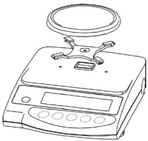
5.2.3 Positioning the weighing plate 15
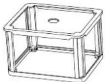
5.2.4 Serial draft shield installation 16
5.2.5 Draft shield installation – optional 17
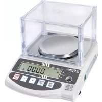
5.2.6 Draft shield with glass sliding doors (only model KERN EW 120-4NM standard)....17
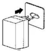
5.3 Mains supply 18
5.4 Operation using a rechargeable battery (optional) 18
5.5 Connecting peripheral equipment....19
5.6 Initial start-up 19
5.6.1 Power display 19
5.6.2 Bar graph display 19
5.6.3 Stability indication 20
5.6.4 Zero display on the balance 20
5.7 Adjustment....21
5.8 Adjusting....21
5.8.1 Adjusting with externall weight (only KERN EW-N) 21
5.8.2 Adjusting with internal weight (only KERN EG) 21
5.8.3 Adjusting with external weight (only KERN EW) 23
5.9 Verification....25
5.10 Verification switch and official seal 26
6 Operation 27
6.1 Operating elements....27
6.1.1 Overview of the keypad....28
6.1.2 Overview of display 29
6.2 Operation 30
6.2.1 Weighing 30
6.2.1.1 Underfloor weighing.... 31
6.2.1.2 Tare weighing (tare) 32
6.2.2 Piece counting (excl. model KERN EW120-4NM) 34
6.2.2.1 Add mode 36
6.2.3 Percent weighing (excl. model KERN EW120-4NM) 38
6.2.4 Weighing using a tolerance range (excl. model KERN EW120-4NM) 39
6.2.4.1 Basic settings when weighing using a tolerance range 40
6.2.4.2 Entering the limit values by weighing.... 42
6.2.4.3 Entering the limit values using the keyboard 44
7.1 Access and changing of numerous functions: 46
7.2 List of the function parameters 47
7.2.1 Parameters when weighing with a tolerance range (excl. model KERN EW120-4NM)..... 49
7.2.2 Parameters for the serial interface 50
7.2.3 Show software status 51
8.1 Description of the serial data output (RS 232C) 52
8.2 Technical data of the interface 52
8.3 Interface description....53
8.4 Data Output 53
8.4.1 Data Transmission Formats....53
8.4.2 Algebraic sign....54
8.4.3 Data....54
8.4.4 Units 55
8.4.5 Result of the evaluation / Type of data 55
8.4.6 Data state 55
8.5 Data input commands.... 56
8.5.1 Command input format....56
8.5.2 External taring command 56
8.5.3 External control commands.... 56
8.6 Feedback message after data transmission 57
9.1 Cleaning 57
9.2 Maintenance, upkeep....57
9.3 Disposal 57
7 Functions 46
8 Data output 52
9 Maintenance, upkeep, disposal.... 57
10 Troubleshooting....58
11 Declaration of Conformity 59
1 Technical data
| KERN (Type) | EG 200-3AM | EG 400-3AM | EG 600-3AM |
| Model | EG 220-3NM | EG 420-3NM | EG 620-3NM |
| Readout | 0,001 g | 0,001 g | 0,001 g |
| Verification value (e) | 0,01 g | 0,01 g | 0,01 g |
| Weighing range (max.) | 220 g | 420 g | 620 g |
| Class of accuracy | II | II | I |
| Taring range (subtractive) | 220g | 420 g | 620 g |
| Minimum load (Min) | 0,02 g | 0,02 g | 0,1 g |
| Minimum weight for counting parts | 0,001 g | 0,001 g | 0,001 g |
| Reference quantity | 10, 30, 50, 100 | 10, 30, 50, 100 | 10, 30, 50, 100 |
| Minimum unit weight at piece counting under laboratory conditions* | 0,001 g | 0,001 g | 0,001 g |
| Minimum unit weight at piece counting under normal conditions** | 0,01 g | 0,01 g | 0,01 g |
| Reproducibility | 0,001 g | 0,001 g | 0,001 g |
| Linearity | ± 0,002 g | ± 0,003 g | ± 0,004 g |
| Adjusting weight | internal | internal | internal |
| Stabilization time | 3 sec. | 3 sec. | 3 sec. |
| Weighing plate stainless steel | ∅ 118 mm | ∅ 118 mm | ∅ 118 mm |
| Weight kg (net) | 2,0 | 2,0 | 2,0 |
| Units, verification switch in verification position,(chap. 5.10) | g, ct | ||
| Units , verification switch not in verification position,(chap. 5.10) | g, ct, oz, lb, ozt, dwt, GN, tl (HongKong), tl (Taiwan),tl (Singapore, Malaysia), momme, tola | ||
| Air humidity | max. 80 % relative (not condensing) | ||
| Permissible ambient condition | 10°C to 30°C | ||
| Balance dimensions | 235 x 180 x 75 mm (excluding draft shield)235 x 185 x 165 mm (including draft shield) | ||
| Vibratory filter | 4 | ||
| Mains supply | Mains adaptor 100-240 V AC, 50/60 Hz ; 12 V DC balance, 1A | ||
| Interface | RS 232 C interfaced | ||
| Rechargeable battery | optional; 6 V DC, 2000 mAh | ||
| Underfloor weighing | Hanging loop optional | ||
| Altitude | Up to 2000 m | ||
| Pollution Degree | 2 | ||
| Installation Site | device may only be used indoors | ||
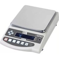
| KERN (Type) | EG 2000-2AM | EG 4000-2AM |
| Model | EG 2200-2NM | EG 4200-2NM |
| Readout | 0,01 g | 0,01 g |
| Verification value (e) | 0,1 g | 0,1 g |
| Weighing range (max.) | 2200 g | 4200 g |
| Class of accuracy | II | II |
| Taring range (subtractive) | 2200 g | 4200 g |
| Minimum load (Min) | 0,5 g | 0,5 g |
| Minimum weight for counting parts | 0,01 g | 0,01 g |
| Reference quantity | 10, 30, 50, 100 | 10, 30, 50, 100 |
| Minimum unit weight at piece counting under laboratory conditions* | 0,01 g | 0,01 g |
| Minimum unit weight at piece counting under normal conditions** | 0,1 g | 0,1 g |
| Reproducibility | 0,01 g | 0,01 g |
| Linearity | ±0, 02 g | ±0,02 g |
| Adjusting weight | internal | internal |
| Test weight, included | - | - |
| Recommended adjusting weight, not included (class) | - | - |
| Stabilization time | 3 sec. | 3 sec. |
| Weighing plate stainless steel | 180 x 160 mm | 180 x 160 mm |
| Weight kg (net) | 3,7 | 3,7 |
| Units, verification switch in verification position,(chap. 5.10) | g, ct | |
| Units , verification switch not in verification position,(chap. 5.10) | g, ct, oz, lb, ozt, dwt, GN, tl (HongKong), tl (Taiwan), tl (Singapore, Malaysia), momme, tola | |
| Air humidity | max. 80 % relative (not condensing) | |
| Permissible ambient condition | 10°C to 30°C | |
| Balance dimensions excluding draft shield | 190 x 265 x 90 mm | |
| Vibratory filter | 4 | |
| Mains supply | Mains adaptor 100-240 V AC, 50/60 Hz ; 12 V DC balance, 1A | |
| Interface | RS 232 C interfaced | |
| Rechargeable battery | optional; 6 V DC, 2000 mAh | |
| Underfloor weighing | Hanging loop optional | |
| Altitude | Up to 2000 m | |
| Pollution Degree | 2 | |
| Installation Site | device may only be used indoors | |
| KERN | EW 220-3NM | EW 420-3NM | EW 620-3NM |
| Readout | 0,001 g | 0,001 g | 0,001 g |
| Verification value (e) | 0,01 g | 0,01 g | 0,01 g |
| Weighing range (max.) | 220 g | 420 g | 620 g |
| Class of accuracy | II | II | I |
| Taring range (subtractive) | 220g | 420 g | 620 g |
| Minimum load (Min) | 0,02 g | 0,02 g | 0,1 g |
| Minimum weight for counting parts | 0,001 g | 0,001 g | 0,001 g |
| Reference quantity | 10, 30, 50, 100 | 10, 30, 50, 100 | 10, 30, 50, 100 |
| Minimum unit weight at piece counting under laboratory conditions* | 0,001 g | 0,001 g | 0,001 g |
| Minimum unit weight at piece counting under normal conditions** | 0,01 g | 0,01 g | 0,01 g |
| Reproducibility | 0,001 g | 0,001 g | 0,001 g |
| Linearity | ± 0,002 g | ± 0,003 g | ± 0,004 g |
| Recommended adjusting weight, not included (class) | 200g (F1) | 2 x 200g (E2) | 500 g (E2) |
| Stabilization time | 2 sec. | 2 sec. | 2 sec. |
| Weighing plate stainless steel | ∅ 118 mm | ∅ 118 mm | ∅ 118 mm |
| Weight kg (net) | 1,3 | 1,3 | 1,3 |
| Units, verification switch in verification position,(chap. 5.10) | g, ct | ||
| Units , verification switch not in verification position,(chap. 5.10) | g, ct, oz, lb, ozt, dwt, GN, tl (HongKong), tl (Taiwan), tl (Singapore, Malaysia), momme, tola | ||
| Air humidity | max. 80 % relative (not condensing) | ||
| Permissible ambient condition | 10°C to 30°C | ||
| Balance dimensions | 235 x 180 x 75 mm (excluding draft shield)235 x 185 x 165 mm (including draft shield) | ||
| Vibratory filter | 4 | ||
| Mains supply | Mains adaptor 100-240 V AC, 50/60 Hz ; 12 V DC balance, 1A | ||
| Interface | RS 232 C interfaced | ||
| Rechargeable battery | optional; 6 V DC, 2000 mAh | ||
| Underfloor weighing | Hanging loop optional | ||
| Altitude | Up to 2000 m | ||
| Pollution Degree | 2 | ||
| Installation Site | device may only be used indoors | ||
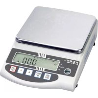
| KERN | EW 820-2NM | EW 2200-2NM | EW 4200-2NM |
| Readout | 0,01 g | 0,01 g | 0,01 g |
| Verification value (e) | 0,01 g | 0,1 g | 0,1 g |
| Weighing range (max.) | 820 g | 2200 g | 4200 g |
| Class of accuracy | I | II | II |
| Taring range (subtractive) | 820 g | 2200 g | 4200 g |
| Minimum load (Min) | 1 g | 0,5 g | 0,5 g |
| Minimum weight for counting parts | 0,01 g | 0,01 g | 0,01 g |
| Reference quantity | 10, 30, 50, 100 | 10, 30, 50, 100 | 10, 30, 50, 100 |
| Minimum unit weight at piece counting under laboratory conditions* | 0,01 g | 0,01 g | 0,01 g |
| Minimum unit weight at piece counting under normal conditions** | 0,1 g | 0,1 g | 0,1 g |
| Reproducibility | 0,01 g | 0,01 g | 0,01 g |
| Linearity | ± 0,01 g | ± 0,01 g | ± 0,02 g |
| Recommended adjusting weight, not included (class) | 1 x 200 g+ 1 x 500 g(F1) | 2000 g (F1) | 2 x 2 kg (E2) |
| Stabilization time | 2 sec. | 2 sec. | 2 sec. |
| Weighing plate stainless steel | 170 x 142 mm | 180 x 160 mm | 180 x 160 mm |
| Weight kg (net) | 1,3 | 2,8 | 2,8 |
| Units, verification switch in verification position,(chap. 5.10) | g, ct | ||
| Units , verification switch not in verification position,(chap. 5.10) | g, ct, oz, lb, ozt, dwt, GN, tl (HongKong), tl (Taiwan),tl (Singapore, Malaysia), momme, tola | ||
| Air humidity | max. 80 % relative (not condensing) | ||
| Permissible ambient condition | 10°C to 30°C | ||
| Balance dimensions excluding draft shield | 180 x 235 x 75 mm | 190 x 265 x 90 mm | |
| Vibratory filter | 4 | ||
| Mains supply | Mains adaptor 100-240 V AC, 50/60 Hz ; 12 V DC balance, 1A | ||
| Interface | RS 232 C interfaced | ||
| Rechargeable battery | optional; 6 V DC, 2000 mAh | ||
| Underfloor weighing | Hanging loop optional | ||
| Altitude | Up to 2000 m | ||
| Pollution Degree | 2 | ||
| Installation Site | device may only be used indoors | ||
| KERN | EW 6200-2NM | EW 12000-1NM |
| Readout | 0,01 g | 0,1 g |
| Verification value (e) | 0,1 g | 1 g |
| Weighing range (max.) | 6 200 g | 12 000 g |
| Class of accuracy | I | II |
| Taring range (subtractive) | 6 200 g | 12 000 g |
| Minimum load (Min) | 1 g | 5 g |
| Minimum weight for counting parts | 0,01 g | 0,1 g |
| Reference quantity | 10, 30, 50, 100 | 10, 30, 50, 100 |
| Minimum unit weight at piece counting under laboratory conditions* | 0,01 g | 0,1 g |
| Minimum unit weight at piece counting under normal conditions** | 0,1 g | 1 g |
| Reproducibility | 0,02 g | 0,1 g |
| Linearity | ± 0, 03 g | ± 0,1 g |
| Recommended adjusting weight, not included (class) | 5 kg (E2) | 10 kg (F1) |
| Stabilization time | 3 sec. | 3 sec. |
| Weight kg (net) | 2,8 | 2,8 |
| Units, verification switch in verification position (days 5-10) | g, ct |
g, ct, oz, lb, ozt, dwt, GN, tl (HongKong), tl (Taiwan), tl (Singapore, Malaysia), momme, tola
Air humidity
max. 80 % relative (not condensing)
Permissible ambient condition
10^ to 30^
Weighing plate stainless steel
180 x 160 mm
Balance dimensions
190 x 265 x 90 mm (excluding draft shield)
Vibratory filter
4
Mains supply
Mains adaptor 100-240 V AC, 50/60 Hz ; 12 V DC balance, 1A
Interface
RS 232 C interfaced
Rechargeable battery
optional; 6 V DC, 2000 mAh
Underfloor weighing
Hanging loop optional
Altitude
Up to 2000 m
Pollution Degree
2
Installation Site
device may only be used indoors
* Minimum unit weight at piece counting under laboratory conditions:
➢ Perfect ambient conditions to perform high resolution counting
No dispersion of counted parts weight
**Minimum unit weight at piece counting under normal conditions:
- Unstable ambient conditions (wind gusts, vibrations)
➢ Dispersion of counted parts weight
1.1 Read-off of the various weighing units
| Weighing unit | EG 220-3NM / EW 220-3NM | EG 420-3NM / EW 420-3NM |
| g | 0.001 | 0.001 |
| ct (ct) | 0.01 | 0.01 |
| oz (oz) | 0.0001 | 0.0001 |
| lb (lb) | 0.00001 | 0.00001 |
| oz t (ozt) | 0.0001 | 0.0001 |
| dvt (dwt) | 0.001 | 0.001 |
| ► (grain) | 0.1 | 0.1 |
| tl (Hong Kong) | 0.0001 | 0.0001 |
| tl (Singapore,Malaysia) | 0.0001 | 0.0001 |
| tl (Taiwan) | 0.0001 | 0.0001 |
| mom | 0.001 | 0.001 |
| to (to) | 0.0001 | 0.0001 |
| Weighing unit | EG 620-3NM / EW 620-3NM | EW 820-2NM | EG 2200-2NM/ EW 2200-2NM |
| g | 0.001 | 0.01 | 0.01 |
| ct (ct) | 0.01 | 0.05 | 0.1 |
| oz (oz) | 0.0001 | 0.0005 | 0.001 |
| lb (lb) | 0.00001 | 0.00005 | 0.0001 |
| oz t (ozt) | 0.0001 | 0.0005 | 0.001 |
| dvt (dwt) | 0.001 | 0.01 | 0.01 |
| tl (Hong Kong) | 0.1 | 0.0005 | 0.001 |
| tl (Singapore,Malaysia) | 0.0001 | 0.0005 | 0.001 |
| tl (Taiwan) | 0.0001 | 0.0005 | 0.001 |
| mom | 0.0001 | 0.005 | 0.01 |
| to (to) | 0.001 | 0.001 | 0.001 |
| 0.0001 |
| Weighing unit | EG 4200-2NM/EW 4200-2NM | EW 6200-2NM | EW 12000-1NM |
| g | 0.01 | 0.01 | 0.1 |
| ct(ct) | 0.1 | 0.1 | 1 |
| oz (oz) | 0.001 | 0.001 | 0.01 |
| lb (lb) | 0.0001 | 0.0001 | 0.001 |
| oz t(ozt) | 0.001 | 0.001 | 0.01 |
| dvt (dwt) | 0.01 | 0.01 | 0.1 |
| tl (Hong Kong) | 0.001 | 0.001 | 0.01 |
| tl (Singapore,Malaysia) | 0.001 | 0.001 | 0.01 |
| tl (Taiwan) | 0.001 | 0.001 | 0.01 |
| mom | 0.01 | 0.01 | 0.1 |
| to (to) | 0.001 | 0.001 | 0.01 |
1.2 Weighing unit conversion charts
| Weighing unit | Gramm | Carat | Ounze | Pound | Fine ounze | Penny weight |
| 1g | 1 | 5 | 0.03527 | 0.00220 | 0.03215 | 0.64301 |
| 1ct | 0.2 | 1 | 0.00705 | 0.00044 | 0.00643 | 0.12860 |
| 1oz | 28.34952 | 141.74762 | 1 | 0.06250 | 0.91146 | 18.22917 |
| 1lb | 453.59237 | 2267.96185 | 16 | 1 | 14.58333 | 291.66667 |
| 1ozt | 31.10348 | 155.51738 | 1.09714 | 0.06857 | 1 | 20 |
| 1dwt | 1.55517 | 7.77587 | 0.05486 | 0.00343 | 0.05 | 1 |
| 1GN | 0.06480 | 0.32399 | 0.00229 | 0.00014 | 0.00208 | 0.04167 |
| 1tl (HK) | 37.429 | 187.145 | 1.32027 | 0.08252 | 1.20337 | 24.06741 |
| 1tl (SGP,Mal) | 37.79936 | 188.99682 | 1.33333 | 0.08333 | 1.21528 | 24.30556 |
| 1tl (Taiwan) | 37.5 | 187.5 | 1.32277 | 0.08267 | 1.20565 | 24.11306 |
| 1mom | 3.75 | 18.75 | 0.13228 | 0.00827 | 0.12057 | 2.41131 |
| 1to | 11.66380 | 58.31902 | 0.41143 | 0.02571 | 0.37500 | 7.5 |
| Weighing unit | Grain | Tael (Hong Kong) | Tael (Singapore, Malaysia) | Tael (Taiwan) | Momme | Tola |
| 1g | 15.43236 | 0.02672 | 0.02646 | 0.02667 | 0.26667 | 0.08574 |
| 1ct | 3.08647 | 0.00534 | 0.00529 | 0.00533 | 0.05333 | 0.01715 |
| 1oz | 437.5 | 0.75742 | 0.75 | 0.75599 | 7.55987 | 2.43056 |
| 1lb | 7000 | 12.11874 | 12 | 12.09580 | 120.95797 | 38.88889 |
| 1ozt | 480 | 0.83100 | 0.82286 | 0.82943 | 8.29426 | 2.66667 |
| 1dwt | 24 | 0.04155 | 0.04114 | 0.04147 | 0.41471 | 0.13333 |
| 1GN | 1 | 0.00173 | 0.00171 | 0.00173 | 0.01728 | 0.00556 |
| 1tl (HK) | 577.61774 | 1 | 0.99020 | 0.99811 | 9.98107 | 3.20899 |
| 1tl (SGP,Mal) | 583.33333 | 1.00990 | 1 | 1.00798 | 10.07983 | 3.24074 |
| 1tl (Taiwan) | 578.71344 | 1.00190 | 0.99208 | 1 | 10 | 3.21507 |
| 1mom | 57.87134 | 0.10019 | 0.09921 | 0.1 | 1 | 0.32151 |
| 1to | 180 | 0.31162 | 0.30857 | 0.31103 | 3.11035 | 1 |
2 Fundamental information (general)
2.1 Intended use
The balance you have acquired serves to determine the weighing value of the material to be weighed. It is intended to be used as a “non-automatic” balance, i.e. the material to be weighed is manually and carefully placed in the centre of the weighing plate. The weighing value can be read off after a stable weighing value has been obtained.
2.2 Inappropriate use
Do not use the balance for dynamic weighing. In the event that small quantities are removed or added to the material to be weighed, incorrect weighing results can be displayed due to the “stability compensation” in the balance. (Example: Slowly draining fluids from a container on the balance.)
Do not leave a permanent load on the weighing plate. This can damage the measuring equipment.
Be sure to avoid impact shock and overloading the balance in excess of the prescribed maximum load rating (max.), minus any possible tare weight that is already present.
This could cause damage to the balance.
Never operate the balance in hazardous locations. The series design is not explosion-proof.
Structural alterations may not be made to the balance. This can lead to incorrect weighing results, faults concerning safety regulations as well as to destruction of the balance.
The balance may only be used in compliance with the described guidelines. Varying areas of application/planned use must be approved by KERN in writing.
2.3 Guarantee
The guarantee is not valid following
- non-observation of our guidelines in the operating instructions
- use outside the described applications
- alteration to or opening of the device
- mechanical damage and damage caused by media, liquids
- natural wear and tear
- inappropriate erection or electric installation
- overloading of the measuring equipment
2.4 Monitoring the test substances
The metrology features of the balance and any possible available adjusting weight must be checked at regular intervals within the scope of quality assurance. For this purpose, the answerable user must define a suitable interval as well as the nature and scope of this check. Information is available on KERN's home page (www.kern-sohn.com) with regard to the monitoring of balance test substances and the test weights required for this. Test weights and balances can be adjusted quickly and at a reasonable price in KERN's accredited DKD calibration laboratory (return to national normal).
3 Fundamental safety information
3.1 Observe the information in the operating instructions
Please read the operating instructions carefully before erecting and commissioning, even if you already have experience with KERN balances.
3.2 Staff training
The device may only be operated and looked after by trained members of staff.
4 Transport and storage
4.1 Acceptance check
Please check the packaging immediately upon delivery and the device during unpacking for any visible signs of external damage.
4.2 Packaging / return transport

Keep all parts of the original packaging for a possibly required return.
⇒ Only use original packaging for returning.
Prior to dispatch disconnect all cables and remove loose/mobile parts.
→ Reattach possibly supplied transport securing devices.
⇒ Secure all parts such as the glass wind screen, the weighing platform, power unit etc. against shifting and damage.
5 Unpacking, installation and commissioning
5.1 Place of installation, place of use
The balance is constructed in such a way that reliable weighing results can be achieved under normal application conditions.
By selecting the correct location for your balance, you will be able to work quickly and precisely.
Therefore please observe the following at the place of installation:
- Place the balance on a firm, level surface;
- Avoid extreme heat as well as temperature fluctuation caused by installing next to a radiator or in the direct sunlight;
- Protect the balance against direct draughts due to open windows and doors;
- Avoid jarring during weighing;
- Protect the balance against high humidity, vapours and dust;
- Do not expose the device to extreme dampness for longer periods of time. In-admissible bedewing (condensation of air moisture on the device) can occur if a cold device is taken into a significantly warmer environment. In this case, please acclimatise the device for approx. 2 hours at room temperature after it has been disconnected from the mains.
- Avoid static charging of the material to be weighed, weighing container and windshield.
Major display deviations (incorrect weighing results) are possible if electromagnetic fields occur as well as due to static charging and instable power supply. It is then necessary to change the location.
5.2 Unpacking
Carefully remove the balance from its packaging, remove the plastic wrapping and position the balance in its intended working location.
5.2.1 Installation
Use the foot screws to level the balance until the air bubble in the bubble level is in the prescribed circle.
5.2.2 List of items supplied
Standard accessories:
(1) Balance
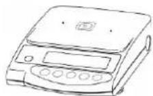
(3) Weighing plate bracket
(2) Weighing plate
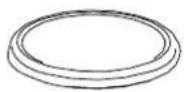
(4) Windbreak
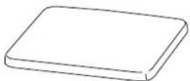
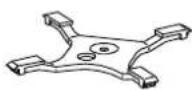
(5) Operating instructions
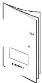
(6) Mains adaptor
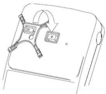
5.2.3 Positioning the weighing plate
natural_image
Line drawing of a digital balance scale with a top handle and control panel (no text or symbols)Screw the bracket on tightly according to the drawing and subsequently attach the weighing plate.
natural_image
Line drawing of a device with two accessories and a curved arrow indicating rotation (no text or symbols)5.2.4 Serial draft shield installation
(Only for models with readout d = 0,001 g standard)
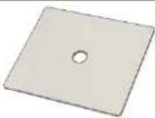 | 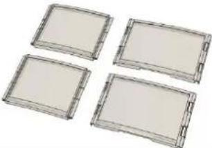 |
| Cover | Sides(2 large, 2 small) |
| Slide the small side (1) into the large side (2) | 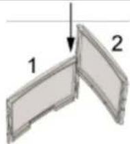 | |
| Properly attach another large side to both sides. | 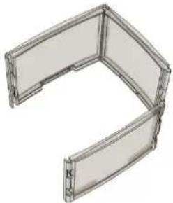 | |
| Install the fourth side as shown in the figure. | 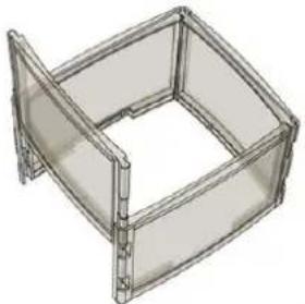 | |
| Put the cover on the assembled sides. | 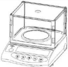 |
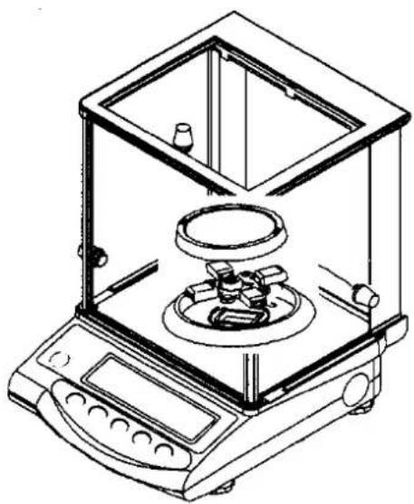
5.2.5 Draft shield installation – optional
Remove the weighing plate and loosen the screws to remove the bracket. Use a screwdriver to loosen both screws to the left and right of the bracket guide and remove.
Now place the draft shield to fit on the housing and and secure through the opened sliding doors using both screws.
Screw the bracket on tightly according to the drawing and subsequently attach the weighing plate.
5.2.6 Draft shield with glass sliding doors
(only model KERN EW 120-4NM standard)
natural_image
Line drawing of an analog laboratory balance with a digital counter and mechanical components (no text or symbols)5.3 Mains supply
Electric power supply is by means of the external mains supply circuit. The printed voltage level must comply with the local voltage.
Only use original KERN mains supply circuits. The use of other makes is subject to approval by KERN.
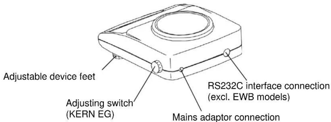
Mains adaptor connection:
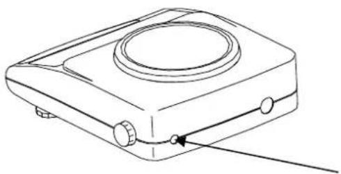
natural_image
Line drawing of a portable electronic device with a circular top and control buttons (no text or symbols)Mains adaptor connection
5.4 Operation using a rechargeable battery (optional)
Take off the weighing plate and remove the bracket by loosening the screw. Use a screwdriver to loosen both screws to the left and right of the bracket guide and remove.
Release both retaining hooks on the lower housing section and carefully remove the lower housing section to the rear (please observe the upper housing section guides on the back of the balance).
Loosen and remove both fastening screws as shown on the illustration.
Remove the rechargeable battery from the packaging and begin by connecting the electric power supply to the circuit board of the rechargeable battery.
Subsequently set up the plug-in connection to the computer circuit board of the balance (CN5).
The rechargeable battery is placed on the left side of the housing in such a way that it can be screwed onto the balance through the existing mounting using the screw loosened previously. Press lightly into the housing prior to this, (there is only one correct installation possibility). Now also re-attach the display using the loosened screw.
Place the upper housing section on the rear guides and tilt forward until both retaining hooks on the lower housing section audibly lock into place.
Screw down both screws to the left and right of the bracket guide tightly and re-se-cure the bracket. Attach the weighing plate.
Information:
Though the rechargeable battery is immediately operative, it should be charged for at least 8 hours using the mains adaptor before being used for the first time.
5.5 Connecting peripheral equipment
The balance must be disconnected from the mains before connecting or disconnecting additional equipment (printer, PC) to or from the data interface (see chap. 8.)
Only use KERN accessories and peripheral equipment with your balance. These have been ideally coordinated to your balance.
5.6 Initial start-up
A warm-up time of 10 minutes stabilises the measured values after switching on.
The accuracy of the balance depends on the local acceleration of the fall.
Please be sure to observe the information in the chapter on adjusting (chap. 5.7).
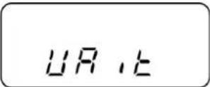
5.6.1 Power display
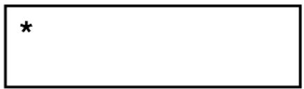
If the (*) sign can be seen, the balance is being supplied with power via the mains adaptor. The balance is in weighing mode when the ON key is operated.
The power display is then no longer to be seen on the display overview.
5.6.2 Bar graph display

weighing dish unloaded half of weighing range to full capacity
weighing range is used
The weighing range of the balance is divided into 20 graphic cuboids. Zero (0) will appear on the graphic display if there is no weighing value on the balance. 10 graphic cuboids are displayed if the balance is loaded up to one half of its weighing range.
Information:
If tare weighing is being carried out, the graphic weight display will continue to indicate the number of cuboids of the tare weight.
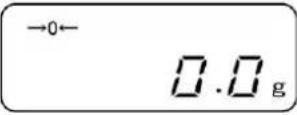
5.6.3 Stability indication
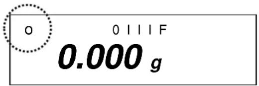
Stable
Unstable
The balance is in a stable condition if the [o] stability indication appears on the display. The [o] indication disappears if the condition is unstable. Stable ambient conditions can be achieved by using the draft shield (See chap. 5.2.4 for installation)
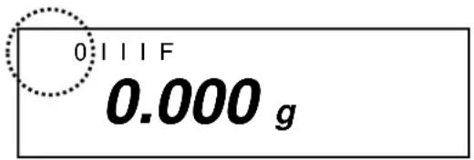
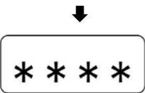
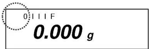
5.6.4 Zero display on the balance
Environmental influences can lead to the exact figure of "0.000" not being displayed in spite of an empty weighing dish. It is, however, possible to reset your balance to zero at any time and thus ensure that weighing really does commence at zero. Setting to zero when a weight is applied is only possible within a certain type-dependent range. In the event that the balance cannot be reset to zero with an applied weight, this range has been exceeded.
[o - Err] will appear on the display.
| Operation | Display |
| If an exact zero reading is not displayed on the balance in spite of the weighing dish being empty, press thekeyand the balance will start resetting to zero. | |
| Your balance will be set to zero after a short standby time.In addition to this, the sign for the balance zero setting will be displayed [→0←]. | →0← 0111F0.000g |
5.7 Adjustment
As the acceleration value due to gravity is not the same at every location on earth, each balance must be coordinated – in compliance with the underlying physical weighing principle - to the existing acceleration due to gravity at its place of location ( only if the balance has not already been adjusted to the location in the factory). This adjustment process must be carried out at every start-up, after every change of location as well as in case of fluctuating environment temperature. It is also recommendable to adjust the balance periodically during weighing operation in order to obtain exact measured values.
5.8 Adjusting
5.8.1 Adjusting with externall weight (only KERN EW-N)
For verified balances the verification switch is locked (except for class of accuracy I). In order to proceed with the verification, please unlock the verification switch (except for class of accuracy I).
5.8.2 Adjusting with internal weight (only KERN EG)
Adjust the balance prior to any start-up.
If the supply voltage is disconnected, the scale must be calibrated.
It is not possible to use the scale without prior adjustment.
Using a precision weight, the accuracy of the balance can be checked at any time and adjusted.
Adjustment procedure:
Check that the surrounding conditions are stable.
A short warm-up time of about 10 minutes is recommended for stabilisation.
| Operation | Display |
| Switch-on balance with button after a short time [S.A. CAL] will appear. | S.A. CAL |
| Press buttons and at the same time and release at the same time, [WAIT] is briefly displayed.After that [CAL.0] will appear flashing, Zero point will be saved.After that [CAL.on] will appear. | CALWAit↓CAL CAL. 0↓CALCAL. on↓ |
Rotate the turn knob on the right side of the balance in to position CAL.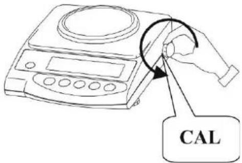 Adjustment is carried out automatically.[CAL.on] will appear flashing. Adjustment is carried out automatically.[CAL.on] will appear flashing. |  |
| The display changes automatically from [CAL.on] to [CAL.OFF]The process of adjustment is completed. | CALCAL. oFF |
5.8.3 Adjusting with external weight (only KERN EW)
Carry out adjustment with the recommended adjusting weight (see Chapter 1 „Technical Data“). The adjustment can also be carried out with different adjusting weights (see table), but not ideal from a metrological point of view. Information concerning the adjusting weights is available at: http://www.kern-sohn.com
Adjustment procedure:
Check that the surrounding conditions are stable.
A short warm-up time of about 10 minutes is recommended for stabilisation.
| Operation | Display |
| Switch on the balance using the key | |
| Press and hold the key until [CAL] appears. Now release the key. | 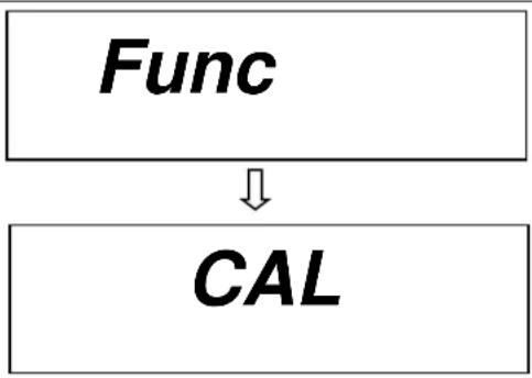 |
| Press the key while holding down the TARE key. Subsequently release both keys simultaneously.↓The zero point will be stored. | 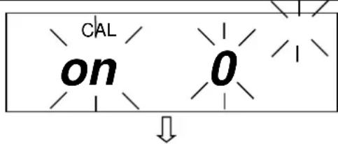  |
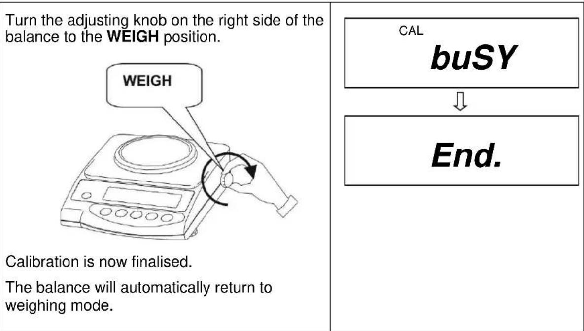
Place the adjusting weight carefully on the centre of the weighing plate.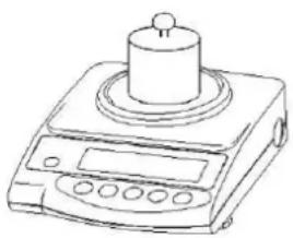 Display flashing [on F.S] then a moment later the weight value of the adjusting weight will be indicated.Remove the adjusting weight, the adjusting is terminated.The balance will automatically return to weighing mode.In case of an adjusting error or a wrong adjusting weight [-Err] appears in the display, repeat the adjustment procedure. Display flashing [on F.S] then a moment later the weight value of the adjusting weight will be indicated.Remove the adjusting weight, the adjusting is terminated.The balance will automatically return to weighing mode.In case of an adjusting error or a wrong adjusting weight [-Err] appears in the display, repeat the adjustment procedure. | 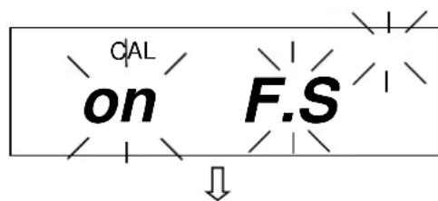 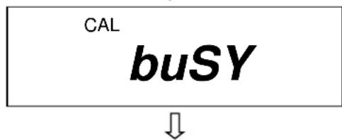  |
5.9 Verification
General:
According to the EU guideline 2014/31/EU balances must be verified if they are to be used as follows (legally regulated area):
a) For commercial transactions if the price of goods is determined by weighing
b) For the production of medines in pharmacies as well as for analyses in the medical and pharmaceutical laboratory
c) For official purposes
d) For the production of finished packages
In case of doubt, please contact your local office of weights and measures.
Verification information
An EU qualification approval is available for those balances marked as appropriate for verification in the technical data. In the event that the balance is applied in an area subject to verification as described above, it must be verified and re-verified at regular intervals.
Re-verification of a balance is carried out in compliance with the respective legal provisions of the states. The term of verification validity for balances in Germany, for example, is normally 2 years.
The legal provisions of the country of use are to be observed.
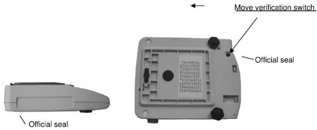
5.10 Verification switch and official seal
Prior to verification the verification switch must be moved from the displayed position (see direction of arrow) to verification position. Once in this position, a parenthesis will be displayed around the last display point.
Following calibration the balance is sealed at the marked position.
Balance calibration is not valid without the "official seals".
Position of the "official seals":
Balances that are subject to compulsory verification must be taken out of operation if:
- The weighing result of the balance is outside the error limit. Therefore, apply a known test weight (approx. 1/3 of the nominal load) to the balance at regular intervals and compare with the display value.
• The reverification deadline has been exceeded.
6 Operation
6.1 Operating elements
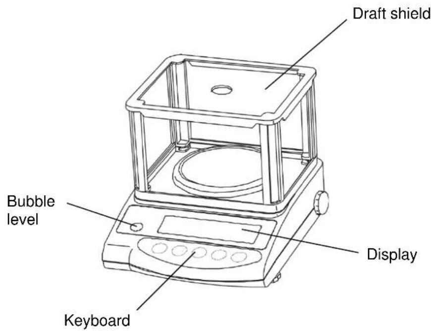
6.1.1 Overview of the keypad
| Choice | Function |
 | Switch on and off |
 | Output of weight value on an external device (printer) or PCSave the respective mode settings (unit counter, percent weighing, tolerance weighing) |
 | Unit counter and percent mode:Choice menu for unit and %Save function parametersCall up lower and upper tolerance levels |
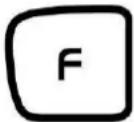 | Key to alter the weight unit (g, ct, Pcs, %)Entry of lower and upper tolerance levelsChoosing the function values within the functionCall up individual functions (multiple print)Call up adjusting functions (permanent print)The entry point is moved to the left each time by one step (chap. 6.2.4.3). |
 | Tare or set weight display to zero |
6.1.2 Overview of display
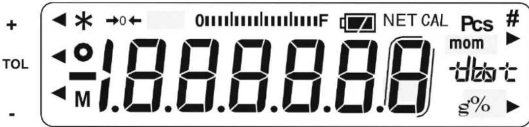
| Display | Description |
| g | Gramme |
| →0← | Zero setting display |
| o | Stability indication |
| * | Power display (standby) |
| Pcs | Unit counter display (excl. EW 120-4NM) |
| % | Percent weighing display (excl. EW 120-4NM) |
| Tolerance weighing display (excl. EW 120-4NM) | |
| mom | Momme |
| M | Balance carry out balance function, e.g. unit count / display of stored value |
| CAL | Calibration display. Signalises calibration procedure. |
| 0 F | Bar graph |
| Indication of weighing units | [ct] (ct) carat |
| [oz] (oz) ounce | |
| [lb] (lb) pound | |
| [oz t] (ozt) fine ounce | |
| [dvt] (dwt) penny weight | |
| [▶ (upper right)] grain | |
| [tl] (tl) Tael (Hong Kong) | |
| [tl ▶ upper right] (tl ▶ upper right) Tael (Singapore, Malaysia) | |
| [tl ▶ lower right] (tl ▶ lower right) Tael (Taiwan) | |
| [to] (to) Tola | |
| Rechargeable battery mode (optional). [□□] Display changes to mains-powered mode if the voltage falls below the prescribed minimum. |
6.2 Operation
6.2.1 Weighing
Display symbol: g
| Operation | Display |
| Press the ON key to switch on the balance.The balance will carry out a self-test. | 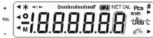 |
| Your balance is ready to weigh as soon as the "0.000" display appears.Apply the item to be weighed. The weight value is displayed. | 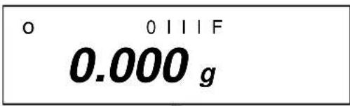 ↓ ↓ |
A switch can be made from one unit to another,e.g. from "g" to another unit, for example "ct",by repeatedly pressing the key. Setting –see chapter 7 on "Functions".[g] → [ct] → [Pcs] → [%] → [g] → ......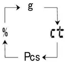 Press the ON key to switch the balance off. Press the ON key to switch the balance off. | 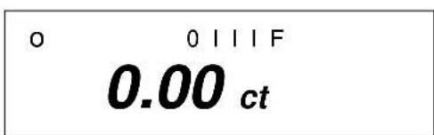 ↓ ↓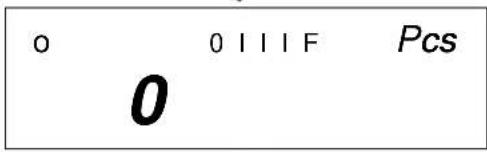 ↓ ↓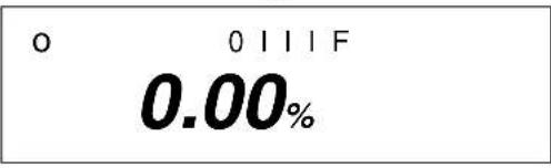 |
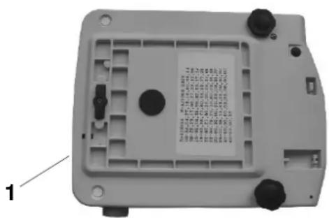
6.2.1.1 Underfloor weighing
Objects which, because of their size or shape, cannot be put on the scale, can be weighed by means of underfloor weighing.
Proceed as follows:
- Switch off the balance.
- Turn the balance over.
- Open the cover plate (1) on the base of the balance.
- Hang on the hanging loop (optional) completely for underfloor weighing.
- Place the balance over an opening.
- Hang the item to be weighed on the hanging loop and carry out weighing.

CAUTION
Take care that the hooks used for the underfloor weighing are stable enough to hold the goods which you wish to weigh (risk of breakage).
Always make sure that there are no living beings or materials below the load that could be injured or damaged.

NOTE
After completing the underfloor weighing, the opening in the floor of the balance must be closed again (dust protection).
6.2.1.2 Tare weighing (tare)
The empty weight of any weighing container can be tared at the push of a button, so that the net weight of the item to be weighed is displayed during subsequent weighings.
| Operation | Display |
Place the empty tare container on the weighing plate. The total weight of the applied container is displayed. | 0 1 1 1 F23.456 g |
Press thekey to start the tare procedure.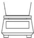 The weight of the container is now stored internally. The weight of the container is now stored internally. | →0← 0 1 1 1 F0.000 g |
Place the items to be weighed in the tare container.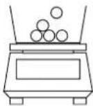 Now read off the weight of the items on the display. Now read off the weight of the items on the display. | 0 1 1 1 F53.258 g |
The tare procedure can be repeated as often as desired, for example when weighing several components into a mixture (weighing in).
Press thekey to set the display to "0.000".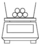 The total weight of the container is removed by taring. The total weight of the container is removed by taring. | →0← 0111F0.000g |
Apply further components to the weighing container (weighing in).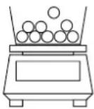 Now read off the weight of the added item to be weighed on the display. Now read off the weight of the added item to be weighed on the display. | 0111F83.456g |
Information:
The balance is only ever able to store one tare value.
The stored tare value is displayed prefixed by a minus sign when the balance is empty.
Remove all items from the weighing plate in order to delete the stored tare value and subsequently press the TARE key.
The tare procedure can be repeated as often as desired. The limit has been reached when the entire weighing range is used to full capacity.
6.2.2 Piece counting
(excl. model KERN EW120-4NM)
Display symbol: PCS
When counting units you can either count items into or out of the container. In order to be able to count a substantial number of items, the average weight per item must be determined using a small quantity (reference units).
The greater the reference unit, the greater the counting accuracy.
A particularly high reference must be chosen for small or greatly varying parts.
The work cycle is divided into four stages:
• Tare the weighing container
• Determine the reference unit
- Weigh in the reference unit
- Count the items
| Operation | Display |
1. Use the key to switch the balance on. Use the key to select unit change-over Pcs(see chap. 6.2.2). | o 0 l l l F Pcs0 |
2. Tare containers can also be used during unit counting. Before starting unit counting use the key to tare out the container. | o 0 l l l F Pcs0 |
3. Operate the key.The reference unit will flash on the display. | |
4. Further reference units of 10, 30, 50 and 100 can be called up by repeatedlyoperating thekey.Important: The greater the reference unit, the more accurate the unit count.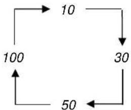 | 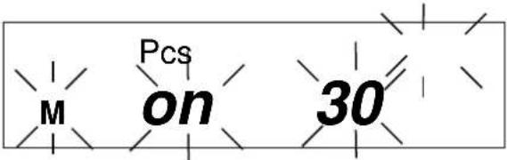 |
5. Place as many items to be counted on the balance as required by the set reference unit.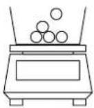 | 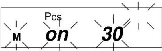 |
6. Operate thekey.The reference unit is stored.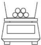 Now place the items to be counted in the container. The appropriate number of items will be shown on the display. Now place the items to be counted in the container. The appropriate number of items will be shown on the display. | 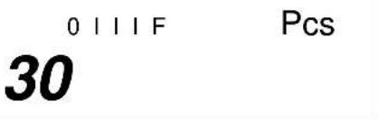 |
7. Use thekeyto return to the desired weighing mode.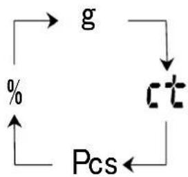 |
Information:
If the "L-Err" error message is displayed, the smallest counting weight has been fallen short of – see chap. 1 "Technical Data".
6.2.2.1 Add mode
This function is used to increase the counting accuracy by increasing the reference quantity. It can thereby be avoided that an inadequate reference unit is used, as this could lead to inaccurate results.
When applying this function, the necessary minimum number of items is automatically ensured.
| Operation | Display |
1. Carry out item 1-5 as in chap. 6.2.2 “Parts counter”.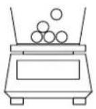 e.g. place 10 items on the weighing plate. e.g. place 10 items on the weighing plate. | 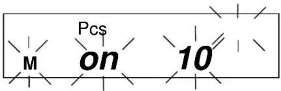 |
2. Operate the Key.The reference weight of the 10 items is stored.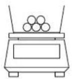 Counting accuracy can be increased by carrying out the following steps. Counting accuracy can be increased by carrying out the following steps. | 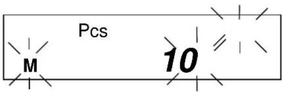 |
3. Doubling the items to be weighed:Apply a further 10 items (approx.).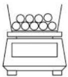 Operate the KeyThe reference weight of the 20 items is stored. Operate the KeyThe reference weight of the 20 items is stored. | 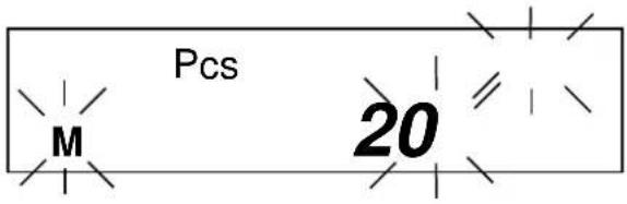 |
4. Double again (see item 3)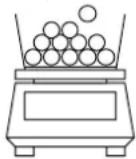 Information:Every additionally applied number of items increases the reference and improves the counting accuracy.A particularly high quantity of reference units must be chosen for small items or items with greatly varying own weight. Information:Every additionally applied number of items increases the reference and improves the counting accuracy.A particularly high quantity of reference units must be chosen for small items or items with greatly varying own weight. | 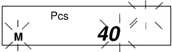 |
5. Operate theThe reference u ed. Now place the items to be counted in the container. The appropriate number of items will be shown on the display Now place the items to be counted in the container. The appropriate number of items will be shown on the display | 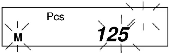 |
Use the key to return to the desired weighing mode.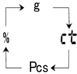 |
Information:
- If the "Add" error message appears, the applied number of items is too small for correct determination of the reference. Place further items on the balance to determine the reference.
- The determined reference is preserved until the balance is disconnected from the mains.
6.2.3 Percent weighing
(excl. model KERN EW120-4NM)
Display symbol: %
Percent weighing allows the weight to be displayed as a percentage in relation to a reference weight. The displayed weight value is adopted as a fixed prescribed percent value. (Standard setting: 100%).
| Operation | Display |
1. Use the key to switch the balance on. Use the key to select unit change-over [%] (see chap. 6.2.1).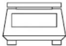 Information:Tare containers can also be used during percent weighing. Before starting per-cent weighing use the key to tare out the container. Information:Tare containers can also be used during percent weighing. Before starting per-cent weighing use the key to tare out the container. | 0 0 1 1 1 F0 % |
2. Operate the key.[P. SET] will flash on the display.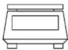 | P. SET % |
3. Place the reference weight = 100% in the balance dish.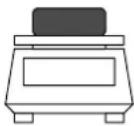 | P. SET % |
4. Operate the key.The reference weight is stored. | 0 0 1 1 1 F100.00 % |
From now on the applied weight is shown as a percentage.

Use the key to return to the desired weighing mode.
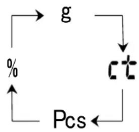
flowchart
graph TD
    g --> ct
    ct --> Pcs
    Pcs --> %
0111F
85.37 %
Information:
- If the "o-Err" error message appears:
- the reference weight is outside the weighing range (see chap. 1 "Technical Data").
- the set key was operated during step 2 when the weight had been applied.
- The 100% reference is preserved until the balance is disconnected from the mains.
6.2.4 Weighing using a tolerance range
(excl. model KERN EW120-4NM)
This balance can be used as a measuring and sorting balance, whereby the respective lower and upper tolerance limits are programmable.
Limit values can be entered in the following operating modes:
- Weighing
- Unit counting
- Percent weighing
6.2.4.1 Basic settings when weighing using a tolerance range
| Operation | Display |
1. Use the  to switch the balance on.[2V=2]Call up the function menu:Press the key until [Func] appears, then release.[6H=3]The first balance mode will appear: to switch the balance on.[2V=2]Call up the function menu:Press the key until [Func] appears, then release.[6H=3]The first balance mode will appear: | 0 0 I I I F   |
2. Tolerance weighingOperate the key to call up tolerance weighing mode.2.SEL 0 (Off)2.SEL 1 (ON)Use the  to change the standard factory configuration. to change the standard factory configuration. |   |
| 3. Tolerance mark displayOperate the key. The tolerance mark is always displayed (factory setting).[KWAR]Use the key to change the setting (1 / 2).The tolerance mark is only displayed when the balance display is at a standstill. | [S444T S444S1][C445T   |
| 4. Setting the tolerance rangeOperate thekeyThe tolerance mark is displayed in all ranges.Use thekeyto change the setting:Tolerance mark is only displayed above a zero point range (+5). | |
| + 0111F- 0.000g22.L1.1↓22.L1.0 | |
| 5. Number of tolerance pointsUse thekeyto set the tolerance mark.1 tolerance mark can be displayed:-◀ too light↓Use thekeyto change the setting:2 tolerance marks can be displayed:+◀ too heavyTOL target value-◀ too light | |
| 23.P1.1↓23.P1.2 | |
| Operate thekey:You will now leave the function menu and return to weighing mode. | o 0111F0.000g |
6.2.4.2 Entering the limit values by weighing
Important information!
Always begin by entering the lower limit value, followed by the upper limit value.
| Operation | Display |
| 1. Use the key to switch the balance on. Set to tolerance weighing:Press the key until [L. SET] appears and then release. | 0 0 I I IF0.000 g L. SET |
2. The tolerance mark ◀ will flash [- ].The lower limit value can be set.Place a sample for the lower (i.e. smaller) limit value on the weighing plate: Store using the key. The stored lower weight value is displayed briefly. Entry is now completed if 1 tolerance mark was selected in the basic setting (see chap. 7.2.1).4. If 2 tolerance marks have been selected, the upper limit value must now be determined.The tolerance mark ◀ is flashing [ + ], and the upper limit value can be set.Place a sample for the upper (i.e. larger) limit value on the weighing plate: Store using the key. The stored lower weight value is displayed briefly. Entry is now completed if 1 tolerance mark was selected in the basic setting (see chap. 7.2.1).4. If 2 tolerance marks have been selected, the upper limit value must now be determined.The tolerance mark ◀ is flashing [ + ], and the upper limit value can be set.Place a sample for the upper (i.e. larger) limit value on the weighing plate: | M 0.000 gM 93.835 g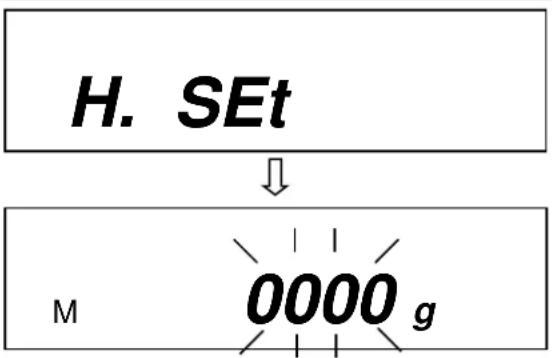 |
5. Use the print key to store. The stored upper weight value is displayed briefly; entry is completed. | M 158.487g |
6.2.4.3 Entering the limit values using the keyboard
| Operation | Display |
1. Use the  to switch the balance on. to switch the balance on. Set tolerance weighing:Press the key until [L. SEt] appears and then release. Set tolerance weighing:Press the key until [L. SEt] appears and then release. | 0 0 I I I F ↓ ↓ |
2. Flashing display is either 000.000 or the currently stored lower limit value.Press the  y:The last digit in the display starts to flash. y:The last digit in the display starts to flash. | M  ↘/↘ ↘/↘ |
3. Use the  y to increase the numerical value of the selected digit. y to increase the numerical value of the selected digit. | M  ↘/↘ ↘/↘ |
4. Use the  y to select the digit you wish to alter (from right to left). y to select the digit you wish to alter (from right to left). | M  ↘/↘ ↘/↘ |
| 5. Further entries as described in items 3 and 4. | M  ↘/↘ ↘/↘ |
6. Use the [DK3AD]y to store. The stored lower weight value is displayed briefly.Entry is now  ompleted if 1 tolerance mark was selected in the basic setting (chap. 7.2.1). ompleted if 1 tolerance mark was selected in the basic setting (chap. 7.2.1). | M  |
| 7. If 2 tolerance marks have been selected, the upper limit value must now be determined.Please proceed as described in item 2, starting with the last display digit. |  |
 | |
| 8. Enter the upper limit value and store. |
7 Functions
7.1 Access and changing of numerous functions:
The balance has been set to a certain standard configuration in the factory. This configuration is marked by a ☆.
The configuration can be changed as follows:
| Operation | Display |
| 1. Access to the functions.Switch on the balance:↓Press the key for about 4 seconds until [FUNC] appears:↓When released the following will appear : (possible configurations are listed in chap. 7.2.2).↓2. Changing the functionsRun through the various functions for configuration by continuing to press the key.↓Operate the key in order to change the last position in the parameter.↓Store the chosen function by operating the key.You will now leave the function menu and return to weighing mode. | 0 0 I I I F ↓ ↓ ↓ ↓ ↓ ↓ ↓ ↓ ↓0 0 I I I F ↓0 0 I I I F |
7.2 List of the function parameters
The balance has been set to a certain standard configuration in the factory. This is marked by a ☆.
| Function | DisplayF | ChoiceTARE→0← | Description of the choice possibilities | |
| Bar graph | 1 | b.G. | 0 | Off |
| ☆1 | On | |||
| Tolerance weighing (excl. EW-120-4NM) | 2 | SEL | ☆0 | Off |
| 1 | On (chap. 7.2.1) | |||
| Only displayed when tolerance weighing is active: | ||||
| Weighing with a tolerance rangePrecondition | 21. | C0. | ☆1 | Checked also when the balance is unstable |
| 2 | Checked also when the balance is stable | |||
| Weighing with a tolerance rangeRange | 22. | Li. | 0 | Checked also when the balance is stable |
| ☆1 | The entire range is checked (including negative values) | |||
| Number of adjustment points for tolerance weighing | 23. | Pi. | 1 | Single point setting (the range between OK and LO is checked) |
| ☆2 | Values above the upper limit and values below the lower limit are configurable (i.e. range between HI, OK and LO) | |||
| Zero alignment | 3 | A.0 | 0 | No zero point correction |
| ☆1 | Automatic zero point correction activated. | |||
| Automatic shutoff after 3 min. for rechargeable battery operation (function is only available in rechargeable battery mode) | 4 | A.P. | 0 | Automatic shutoff deactivated for rechargeable battery operation (optional). |
| ☆1 | Automatic shutoff activated for rechargeable battery operation (optional). | |||
| Display speed | 5 | rE.↓ | 0 | Setting for metering |
| 1 | Sensitive and fast | |||
| 2 | ↓ | |||
| ☆3 | ||||
| 4 | ||||
| 5 | Non-sensitive but slow | |||
| Vibratory filter | 6 | S.d. | 1 | Sensitive and fast (very tranquil installation location). |
| ☆2 | ↓ | |||
| 3 | ||||
| 4 | Non-sensitive but slow (very unsettled installation location). | |||
| 5 | only EW-120-4NM | |||
| 6 | only EW-120-4NM | |||
| Interface(excl. EWB models)Weight unit(only selectable, if the calibration switch is not in the calibration position see Ch. 5.10) | 781↓85 | I.F.S.u. | 0 | Interface not active |
| ☆3 | 6-digit data format | |||
| 4 | 7-digit data format | |||
| 1☆01 | (g)(ct)(oz)(lb)(ozt)(dwt)(grain), (excl. EWB models)(tl Hong Kong)(tl Singapore,Malaysia)(tl Taiwan)(mom)(to)(Pcs) excl. EW-120-4NM(%) excl. EW-120-4NMUnit not set (can not be set at 81.S.u.) | |||
| 2☆14 | ||||
| 15 | ||||
| 16 | ||||
| 17 | ||||
| 18 | ||||
| 19 | ||||
| 1A | ||||
| 1b | ||||
| 1C | ||||
| 1d | ||||
| 1E | ||||
| 3☆20 | ||||
| 4☆IF | ||||
| 5☆00 | ||||
| Not documented | 9. | Ai | 0 | Not documented |
| Extended printout of the calibration protocol(function selectable in EG models only) | 0. | GLP | ☆0 | OFF |
| ☆1 | ON**CALIBRATION**MODEL: S/N: ID: DATA: TIME: *CAL. END NAME********** Header Model Serial no. ID no. Calibration date Calibration time End of calibration Name of person checking | |||
| Data output(only selectable, if the calibration switch is not in the calibration position, see Ch. 5.10) | A. | PrF. | 1 | No printout possible if the last display location is enclosed in brackets. |
| ☆2 | Printout possible even if the last display location is enclosed in brackets. Note: Always select this setting before balance calibration because this menu item can no longer be called up after calibration | |||
| 3 | Printout possible only when the calibration switch is not in the calibration position, see Ch. 5.10. | |||
7.2.1 Parameters when weighing with a tolerance range
(excl. model KERN EW120-4NM)
Settings 21. Co. to 23. P I. can only be set if the tolerance weighing function has been activated.
| Function | DisplayF | ChoiceTARE→0← | Description of the choice possibilities | |
| Display conditions of the tolerance mark | 21. | Co.↓ | ☆12 | Tolerance mark is always dis-played, even if standstill check not yet indicated.Tolerance mark only displayed in connection with standstill check. |
| Tolerance range | 22. | L I. | 0☆1 | Tolerance mark only displayed above the zero point range (at least + 5).Tolerance mark displayed throughout entire range. |
| Setting the tolerance mark | 23. | P I.↓ | 1☆2 | 1 tolerance step is displayed:“-” or “+”2 tolerance steps are displayed:“-” and “+” |
7.2.2 Parameters for the serial interface
(excl. EWB models)
| Function | Display | Choice | Description of the choice possibilities | |
| F | TARE→0← | |||
| Output format at interface | 7 | I.F. | 0 | Interface not active |
| ☆1 | 6-digit data format | |||
| ↓ | 2 | 7-digit data format | ||
| Output condition at interface (Menu setting “7 I.F. [1] or [2]” only) | 71. | o.c. | 0 | No data issued. |
| 1 | Continuous serial output. | |||
| 2 | Continuous serial output upon stabilised display. | |||
| 3 | Output following printing of PRINT/M. | |||
| ↓ | 4 | Automatic output upon stable weighing value. The first value to stabilise is adopted if this is -0.00 or less. No new output until weight is removed and a new load applied. | ||
| 5 | Output upon stabilisation, no output if data unstable. | |||
| 6 | Output upon stabilisation, constant output if data unstable. | |||
| ☆7 | Output following printing of PRINT/M. | |||
| Baud rate | 72. | b.L. | ☆1 | 1200 bps |
| 2 | 2400 bps | |||
| 3 | 4800 bps | |||
| 4 | 9600 bps | |||
| Parity (Menu setting “7 I.F. 2” only) | 73. | PA. | ☆0 | No parity bit |
| 1 | Uneven parity | |||
| 2 | Even parity | |||
7.2.3 Show software status
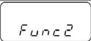 | Press  the time and keep them pressed until „Func2“ will be displayed. the time and keep them pressed until „Func2“ will be displayed. | |
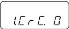 | When released, „1.CrC. 0.“ is displayed. | |
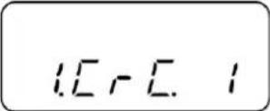 | Use  | |
 | Press  the ba the ba | |
 | ||
 | Return to weighing mode:Press F or TARE →0← |
8 Data output
(excl. EWB models)
The balance is supplied as standard with an interface RS 232C.
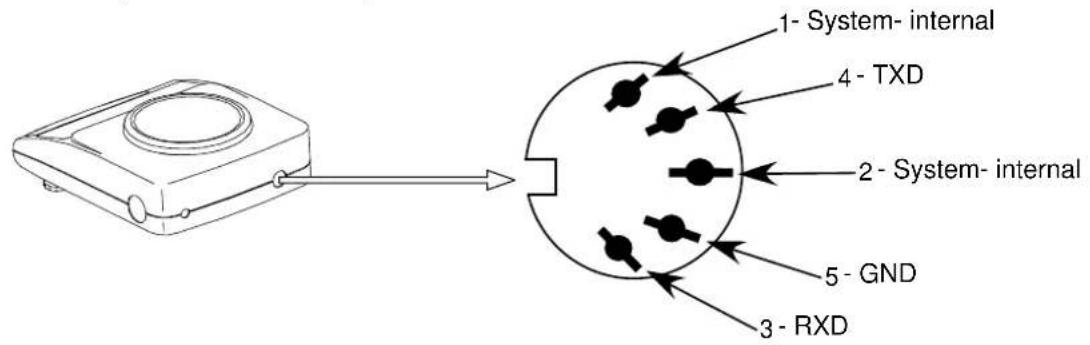
8.1 Description of the serial data output (RS 232C)
The data output is placed at the rear side of the balance. It is a 5-pole standard socket.
Pin description see following illustration
8.2 Technical data of the interface
Transfer format: serial data transfer
Data-bit: 8-bit (Standard-ASCII-Format)
Start-bit: 1 bit
Stop-bit: 2 bits
Parity: NON, ODD, EVEN
Baudrate: 1200 / 2400 / 4800 / 9600 baud can be set
(see chap. 7.2.2 "Functions")
8.3 Interface description
The output format, output control, transfer speed and parity bit can be set following the choice of a certain operating mode. The various possibilities are described in chap.
7.2.2 "Parameters for the serial interface".
8.4 Data Output
8.4.1 Data Transmission Formats
By selecting the corresponding function at your balance one of the two following data formats can be set:
- 6-digit data format
(excl. model KERN EW-120-4NM)
Consisting of 14 words including the final signal; CR=0DH, LF=0AH (CR=return travel / LF=line feed)
| 1 | 2 | 3 | 4 | 5 | 6 | 7 | 8 | 9 | 10 | 11 | 12 | 13 | 14 |
| P1 | D1 | D2 | D3 | D4 | D5 | D6 | D7 | U1 | U2 | S1 | S2 | CR | LF |
- 7-digit data format
| 1 | 2 | 3 | 4 | 5 | 6 | 7 | 8 | 9 | 10 | 11 | 12 | 13 | 14 | 15 |
| P1 | D1 | D2 | D3 | D4 | D5 | D6 | D7 | D8 | U1 | U2 | S1 | S2 | CR | LF |
Note: The 7-digit format is identical with the 6-digit format except for the additional signal D8.
Calibration mark data format
The calibration mark “/” is used to mark the following positions as “non-calibrated”.
- 6-digit data format
6-digit data format for3 the selection of "A.PrF.3" (Printout possible only when the calibration switch is not in the calibration position, see Ch. 5.10.)
Consisting of 15 words including the final signals; CR=0DH, LF=0AH and the calibration mark “/”.
| 1 | 2 | 3 | 4 | 5 | 6 | 7 | 8 | 9 | 10 | 11 | 12 | 13 | 14 | 15 |
| P1 | D1 | D2 | D3 | D4 | D5 | D6 | D7 | D8 | U1 | U2 | S1 | S2 | CR | LF |
- 7-digit data format
7- digit data format for the selection of "A.PrF.3" (Printout possible only when the calibration switch is not in the calibration position, see Ch. 5.10.)
Consisting of 16 words including the final signals; CR=0DH, LF=0AH and the calibration mark “/”.
| 1 | 2 | 3 | 4 | 5 | 6 | 7 | 8 | 9 | 10 | 11 | 12 | 13 | 14 | 15 | 16 |
| P1 | D1 | D2 | D3 | D4 | D5 | D6 | D7 | D8 | D9 | U1 | U2 | S1 | S2 | CR | LF |
8.4.2 Algebraic sign
P 1 = 1 word
| P 1 | Code | Meaning |
| + | 2 B H | Data are 0 or positive |
| - | 2 D H | Data are negative |
| sp | 20 H | Date are 0 or positive |
8.4.3 Data
D 1 to D 7 7 words with 6-digit format (excl. model KERN EW-120-4NM)
D 1 to D 8 8 words with 7-digit format
| D * | Code | Meaning |
| 0 - 9 | 30 H – 39 H | Data 0 to 9 (max. 6 characters in 6-type format) |
| . (Point) | 2 EH | Decimal point, position not fixed |
| Sp | 20 H | Space character, leading zero oppressed |
8.4.4 Units
U 1, U 2 = 2 words as ASCII codes
| U1 | U2 | Code | Meaning | Symbol | |
| (SP) | G | 20H | 47H | Gramme | g |
| C | T | 43H | 54H | Carat | ct |
| O | Z | 4FH | 5AH | Ounze | oz |
| L | B | 4CH | 42H | Pound | lb |
| O | T | 4FH | 54H | Fine ounze | oz t |
| D | W | 44H | 57H | Pennyweight | dvt |
| G | R | 47H | 52H | Grain | ► (upper right) |
| T | L | 54H | 4CH | Tael (Hong Kong) | tl |
| T | L | 54H | 4CH | Tael (Singapore, Malaysia) | tl ► (upper right) |
| T | L | 54H | 4CH | Tael (Taiwan) | tl ► (lower right) |
| M | O | 4DH | 4FH | Momme | mom |
| t | o | 74H | 6FH | Tola | to |
| (SP) | % | 20H | 25H | Percent | % (excl. EW-120-4NM) |
| P | C | 50H | 43H | Quantity | Pcs (excl. EW-120-4NM) |
8.4.5 Result of the evaluation / Type of data
S 1 = 1 Word
| S 1 | Code | MeaningWhen weighing using tolerance range: |
| L | 4 CH | Weighing value below the tolerance range |
| G | 47 H | Weighing value within the tolerance rangeResult of the evaluation issued at two points:Low / high |
| H | 48 H | Weighing value above the talorance range |
8.4.6 Data state
S 2 = 1 Word
| S 2 | Code | Meaning |
| S | 53 H | Stabilised data * |
| U | 55 H | Data not stabilised (fluctuating) * |
| E | 45 H | Data error, all data unreliable with the exception of S 2. Balance displays error (o-Err, u-Err) |
| sp | 20 H | No special status |
8.5 Data input commands
8.5.1 Command input format
is made up of 4 characters, CR=0DH, LF=0AH
| 1 | 2 | 3 | 4 |
| C1 | C2 | CR | LF |
8.5.2 External taring command
| C1 | C2 | Code | Content | |
| T | SP | 54H | 20H | Tare out command |
8.5.3 External control commands
| C1 | C2 | Code | Meaning | |
| O | 0 | 4FH | 30H | No data output |
| O | 1 | 4FH | 31H | Continuous data output |
| O | 2 | 4FH | 32H | Continuous output of stable weight value data |
| O | 3 | 4FH | 33H | Output of stable and unstable weight values after pressing the PRINT button |
| O | 4 | 4FH | 34H | Data output upon stable weight value, having previously unloaded the weighing scale |
| O | 5 | 4FH | 35H | Data output upon stable weight value. No data output at unstable weight value. Data output again, after stabilization has been reached |
| O | 6 | 4FH | 36H | Data output upon stable weight value. Continuous data outputting at unstable weight value. |
| O | 7 | 4FH | 37H | Output of stable weight values after pressing the PRINT button |
| O | 8 | 4FH | 38H | One-time immediate data output* |
| O | 9 | 4FH | 39H | One-time data output after stabilization has been reached* |
| O | A | 4FH | 41H | One-time, immediate data output after lapse of a defined period of time* |
| O | B | 4FH | 42H | One-time, immediate data output after lapse of a defined period of time and upon stable weight value* |
* While using these commands for remote control purposes, do not press the PRINT button (data transmission error). In case data transmission error occurs, briefly cut off the weighing scale from its power supply source.
Remarks:
- Control of data output through "O0\~O7" commands as well as setting up weighing scale's functions, are actions that bring about similar effects.
- Implementation of commands "O8 and O9" is connected with data input commands.
- If any command from the "O0\~O9" range has been carried out, then its status will remain active until the next command is inputted. If, however, the weighing scale is switched off, then the output data control system will return to its previous setup.
8.6 Feedback message after data transmission
is made up of 5 characters, CR=0DH, LF=0AH
| 1 | 2 | 3 | 4 | 5 |
| A1 | A2 | A3 | CR | LF |
Types of feedback messages:
| A1 | A2 | A3 | Code | Description | ||
| A | 0 | 0 | 41H | 30H | 30H | No errors |
| E | 0 | 1 | 45H | 30H | 31H | Error message |
9 Maintenance, upkeep, disposal
9.1 Cleaning
Please disconnect the device from the operating voltage before cleaning.
Only use a cloth dampened with mild suds and not aggressive cleaning agents (solvents or similar). Please ensure that fluids are not able to get into the device and rub off using a clean, soft cloth.
Loose sample residue/powder can be removed carefully using a brush or hand vacuum cleaner.
Remove any spilt material to be weighed immediately.
9.2 Maintenance, upkeep
The device may only be opened by trained service engineers authorised by KERN. Disconnect from the mains supply before opening.
9.3 Disposal
The operating company shall dispose of the packaging and the device in compliance with the valid national or regional law of the operating location.
10 Troubleshooting
The balance should be switched off for a short time following an interruption in the programme sequence and disconnected from the mains supply. It is then necessary to repeat the weighing process from the beginning.
Help:
| Interruption | Possible cause |
| Weight display is not illuminated. | The balance is not switched on.The mains supply connection has been interrupted (mains cable not plugged in/faulty).Power supply interrupted. |
| The weight display changes continually | Draught/air movementTable/floor vibrationsThe weighing plate is in contact with foreign matter.Electromagnetic fields / static charging (choose different location/switch off interfering device if possible) |
| The weighing result is obviously incorrect | The balance display is not set to zeroAdjustment is no longer correct.Great fluctuations in temperature.Electromagnetic fields / static charging (choose different location/switch off interfering device if possible) |
Switch the balance off if other error messages should appear and then switch on again. Contact the manufacturer if the error message does not disappear.
11 Declaration of Conformity
To view the current EC/EU Declaration of Conformity go to:
www.kern-sohn.com/ce
i The scope of delivery for verified weighing balances (= conformity-rated weighing balances) includes a Declaration of Conformity.

KERN EW/EG-N
Version 3.1 2024-05
Mode d'emploi
9.3 Elimination....57
natural_image
Line drawing of a digital balance scale with a circular top and four rotary buttons (no text or symbols)natural_image
Line drawing of a device with two labeled components and an arrow indicating rotation (no text or symbols)natural_image
Line drawing of a laboratory balance with digital scale and mechanical components (no text or symbols)natural_image
Line drawing of a portable electronic device with a circular top and control buttons (no text or symbols)Stable
Instable
Parité: NON, ODD, EVEN
Nombre de configurations possibles : 1200 / 2400 / 4800 / 9600