Multiweld 200M - Welding machine GYS - Free user manual and instructions
Find the device manual for free Multiweld 200M GYS in PDF.

User questions about Multiweld 200M GYS
0 question about this device. Answer the ones you know or ask your own.
Ask a new question about this device
Download the instructions for your Welding machine in PDF format for free! Find your manual Multiweld 200M - GYS and take your electronic device back in hand. On this page are published all the documents necessary for the use of your device. Multiweld 200M by GYS.
USER MANUAL Multiweld 200M GYS
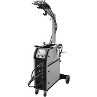
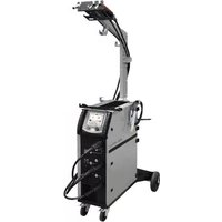
natural_image
Line drawing of a mechanical testing device with wheels and control panel (no text or symbols)MULTIWELD
160M / 200M
FR 2-11 / 80-92
EN 12-20 / 80-92
DE 21-29 / 80-92
ES 30-39 / 80-92
RU 40-49 / 80-92
NL 50-59 / 80-92
IT 60-69 / 80-92
PL 70-79 / 80-92
Poste à souder MIG/MAG et MMA MIG/MAG and MMA welding machine MIG/MAG und E-Hand-Schweißgerät Equipo de soldadura MIG/MAG y MMA Сварочный аппарат МИГ/МАГ и MMA MIG/MAG en MMA Lasapparaat Dispositivo di saldatura MIG/MAG e MMA Urządzenie do spawania MIG/MAG i MMA

AVERTISSEMENTS - RÈGLES DE SÉCURITÉ
CONSIGNE GÉNÉRALE

INSTALLATION - FONCTIONNEMENT PRODUIT
INTERFACE HOMME MACHINE (IHM) (FIG. VI)
General observations :
ANOMALIES, CAUSES, REMÈDES
CONDITIONS DE GARANTIE
Read and understand the following safety recommendations before using or servicing the unit. Any change or servicing that is not specified in the instruction manual must not be undertaken.
The manufacturer is not liable for any injury or damage due to non-compliance with the instructions featured in this manual. In the event of problems or uncertainty, please consult a qualified person to handle the inspection properly.
ENVIRONMENT
This equipment must only be used for welding operations in accordance with the limits indicated on the descriptive panel and/or in the user manual. The operator must respect the safety precautions that apply to this type of welding. In case of inedaquate or unsafe use, the manufacturer cannot be held liable for damage or injury.
This equipment must be used and stored in a place protected from dust, acid or any other corrosive agent. Operate the machine in an open, or well-ventilated area.
Operating temperature:
Use between -10 and +40°C (+14 and +104°F).
Store between -20 and +55°C (-4 and 131°F).
Air humidity:
Lower or equal to 50% at 40°C (104°F).
Lower or equal to 90% at 20°C (68°F).
Altitude:
Up to 1000 meters above sea level (3280 feet).
PROTECTION OF THE INDIVIDUALS
Arc welding can be dangerous and can cause serious and even fatal injuries.
Welding exposes the user to dangerous heat, arc rays, electromagnetic fields, noise, gas fumes, and electrical shocks. People wearing pacemakers are advised to consult with their doctor before using this device.
To protect oneself as well as the other, ensure the following safety precautions are taken:

In order to protect you from burns and radiations, wear clothing without cuffs. These clothes must be insulated, dry, fireproof and in good condition, and cover the whole body.

Wear protective gloves which guarantee electrical and thermal insulation.

Use sufficient welding protective gear for the whole body: hood, gloves, jacket, trousers... (varies depending on the application/operation). Protect the eyes during cleaning operations. Do not operate whilst wearing contact lenses. It may be necessary to install fireproof welding curtains to protect the area against arc rays, weld spatters and sparks.
Inform the people around the working area to never look at the arc nor the molten metal, and to wear protective clothes.

Ensure ear protection is worn by the operator if the work exceeds the authorised noise limit (the same applies to any person in the welding area).
Stay away from moving parts (e.g. engine, fan...) with hands, hair, clothes etc...
Never remove the safety covers from the cooling unit when the machine is plugged in - The manufacturer is not responsible for any accident or injury that happens as a result of not following these safety precautions.
The pieces that have just been welded are hot and may cause burns when manipulated. During maintenance work on the torch or the electrode holder, you should make sure it's cold enough and wait at least 10 minutes before any intervention. The cooling unit must be on when using a water cooled torch in order to ensure that the liquid does not cause any burns.
ALWAYS ensure the working area is left as safe and secure as possible to prevent damage or accidents.
WELDING FUMES AND GAS

The fumes, gases and dust produced during welding are hazardous. It is mandatory to ensure adequate ventilation and/or extraction to keep fumes and gases away from the work area. An air fed helmet is recommended in cases of insufficient air supply in the workplace.
Check that the air intake is in compliance with safety standards
workpiece before welding.
Gas cylinders must be stored in an open or ventilated area. The cylinders must be in a vertical position secured to a support or trolley. Do not weld in areas where grease or paint are stored.
FIRE AND EXPLOSIONS RISKS

Protect the entire welding area. Compressed gas containers and other inflammable material must be moved to a minimum safe distance of 11 meters.
A fire extinguisher must be readily available.
Be careful of spatter and sparks, even through cracks. It can be the source of a fire or an explosion.
Keep people, flammable objects and containers under pressure at a safe distance.
Welding of sealed containers or closed pipes should not be undertaken, and if opened, the operator must remove any inflammable or explosive materials (oil, petrol, gas...).
Grinding operations should not be directed towards the device itself, the power supply or any flammable materials.
GAS BOTTLE

Gas leaking from the cylinder can lead to suffocation if present in high concentrations around the work area.
Transport must be done safely: Cylinders closed and product off. Always keep cylinders in an upright position securely chained to a fixed support or trolley.
Close the bottle after any welding operation. Be wary of temperature changes or exposure to sunlight.
Cylinders should be located away from areas where they may be struck or subjected to physical damage.
Always keep gas bottles at a safe distance from arc welding or cutting operations, and any source of heat, sparks or flames.
Be careful when opening the valve on the gas bottle, it is necessary to remove the tip of the valve and make sure the gas meets your welding requirements.
ELECTRIC SAFETY

The machine must be connected to an earthed electrical supply. Use the recommended fuse size.
An electrical discharge can directly or indirectly cause serious or deadly accidents.
Do not touch any live part of the machine (inside or outside) when it is plugged in (Torches, earth cable, cables, electrodes) because they are connected to the welding circuit.
Before opening the device, it is imperative to disconnect it from the mains and wait 2 minutes, so that all the capacitors are discharged. Do not touch the torch or electrode holder and earth clamp at the same time.
Damaged cables and torches must be changed by a qualified and skilled professional. Make sure that the cable cross section is adequate with the usage (extensions and welding cables). Always wear dry clothes in good condition, in order to be insulated from the electrical circuit. Wear insulating shoes, regardless of the environment in which you work in.
EMC CLASSIFICATION

These Class A devices are not intended to be used on a residential site where the electric current is supplied by the public network, with a low voltage power supply. There may be potential difficulties in ensuring electromagnetic compatibility on these sites, because of the interferences, as well as radio frequencies.

This equipment does not comply with IEC 61000-3-12 and is intended to be connected to private low-voltage systems interfacing with the public supply only at the medium- or high-voltage level. On a public low-voltage power grid, it is the responsibility of the installer or user of the device to ensure, by checking with the operator of the distribution network, which device can be connected.
Provided that the impedance of the low-voltage public electrical network at the common coupling point is less than Zmax = 0.409 Ohms, this equipment complies with IEC 61000-3-11 and can be connected to public low-voltage electrical mains. It is the responsibility of the installer or user of the equipment to ensure, in consultation with the distribution network operator if necessary, that the network impedance complies with the impedance restrictions.
ELECTROMAGNETIC INTERFERENCES
The electric currents flowing through a conductor cause electrical and magnetic fields (EMF). The welding current generates an EMF field around the welding circuit and the welding equipment.
The EMF fields may disrupt some medical implants, such as pacemakers. Protection measures should be taken for people wearing medical implants. For example, access restrictions for passers-by or an individual risk evaluation for the welders.
All welders should take the following precautions in order to minimise exposure to the electromagnetic fields (EMF) generated by the welding circuit::
- position the welding cables together – if possible, attach them;
- keep your head and torso as far as possible from the welding circuit;
- never enroll the cables around your body;
- never position your body between the welding cables. Hold both welding cables on the same side of your body;
- connect the earth clamp as close as possible to the area being welded;
- do not work too close to, do not lean and do not sit on the welding machine
- do not weld when you're carrying the welding machine or its wire feeder.

People wearing pacemakers are advised to consult their doctor before using this device. Exposure to electromagnetic fields while welding may have other health effects which are not yet known.
RECOMMANDATIONS TO ASSES THE AREA AND WELDING INSTALLATION
Overview
The user is responsible for installing and using the arc welding equipment in accordance with the manufacturer's instructions. If electromagnetic disturbances are detected, it is the responsibility of the user of the arc welding equipment to resolve the situation with the manufacturer's technical assistance. In some cases, this remedial action may be as simple as earthing the welding circuit. In other cases, it may be necessary to construct an electromagnetic shield around the welding power source and around the entire piece by fitting input filters. In all cases, electromagnetic interferences must be reduced until they are no longer bothersome.
Welding area assessment
Before installing the machine, the user must evaluate the possible electromagnetic problems that may arise in the area where the installation is planned.
In particular, it should consider the following:
a) the presence of other power cables (power supply cables, telephone cables, command cable, etc...) above, below and on the sides of the arc welding machine.
b) television transmitters and receivers ;
c) computers and other hardware;
d) critical safety equipment such as industrial machine protections;
e) the health and safety of the people in the area such as people with pacemakers or hearing aids;
f) calibration and measuring equipment
g) the isolation of the equipment from other machinery.
The user will have to make sure that the devices and equipments that are in the same room are compatible with each other. This may require extra precautions;
h) make sure of the exact hour when the welding and/or other operations will take place.
The surface of the area to be considered around the device depends on the building's structure and other activities that take place there. The area taken in consideration can be larger than the limits determined by the companies.
Welding area assessment
Besides the welding area, the assessment of the arc welding systems intallation itself can be used to identify and resolve cases of disturbances. The assessment of emissions must include in situ measurements as specified in Article 10 of CISPR 11. In situ measurements can also be used to confirm the effectiveness of mitigation measures.
RECOMMENDATION ON METHODS OF ELECTROMAGNETIC EMISSIONS REDUCTION
a. National power grid: The arc welding machine must be connected to the national power grid in accordance with the manufacturer's recommendation. If interferences occur, it may be necessary to take additional preventive measures such as the filtering of the power supply network. Consideration should be given to shielding the power supply cable in a metal conduit. It is necessary to ensure the shielding's electrical continuity along the cable's entire length. The shielding should be connected to the welding current's source to ensure good electrical contact between the conduct and the casing of the welding current source.
b. Maintenance of the arc welding equipment: The arc welding machine should be submitted to a routine maintenance check according to the manufacturer's recommendations. All accesses, service doors and covers should be closed and properly locked when the arc welding equipment is on. The arc welding equipment must not be modified in any way, except for the changes and settings outlined in the manufacturer's instructions. The spark gap of the arc start and arc stabilization devices must be adjusted and maintained according to the manufacturer's recommendations.
c. Welding cables : Cables must be as short as possible, close to each other and close to the ground, if not on the ground.
d. Electrical bonding : consideration should be given to bonding all metal objects in the surrounding area. However, metal objects connected to the workpiece increase the risk of electric shock if the operator touches both these metal elements and the electrode. It is necessary to insulate the operator from such metal objects.
e. Earthing of the welded part: When the part is not earthed - due to electrical safety reasons or because of its size and its location (which is the case with ship hulls or metallic building structures), the earthing of the part can, in some cases but not systematically, reduce emissions. It is preferable to avoid the earthing of parts that could increase the risk of injury to the users or damage other electrical equipment. If necessary, it is appropriate that the earthing of the part is done directly, but in some countries that do not allow such a direct connection, it is appropriate that the connection is made with a capacitor selected according to national regulations.
f. Protection and plating : The selective protection and plating of other cables and devices in the area can reduce perturbation issues. The protection of the entire welding area can be considered for specific situations.
TRANSPORT AND TRANSIT OF THE WELDING MACHINE

Do not use the cables or torch to move the machine. The welding equipment must be moved in an upright position. Do not place/carry the unit over people or objects.
Never lift the machine while there is a gas cylinder on the support shelf. A clear path is available when moving the item. The removal of the wire reel from the machine is recommended before undertaking any lifting operation.
EQUIPMENT INSTALLATION
- Put the machine on the floor (maximum incline of 10^ .)
- Ensure the work area has sufficient ventilation for welding, and that there is easy access to the control panel.
- The machine must not be used in an area with conductive metal dusts.
- The machine must be placed in a sheltered area away from rain or direct sunlight.
- The machine protection level is IP21, which means :
- Protection against access to dangerous parts from solid bodies of a ≥12.5mm diameter and,
- Protection against vertically falling drops.
The power cables, extensions and welding cables must be fully uncoiled to prevent overheating.
The manufacturer does not incur any responsibility regarding damages to both objects and persons that result from an incorrect and/or dangerous use of the machine.

Stray welding currents/voltages may destroy earth conductors, damage electrical equipment or cause components to warm up which may cause a fire.
- All welding connections must be firmly secured, check regularly!
- Check that the metal piece fixation is strong and without any electrical problems!
- Attach or hang all the electrically conductive elements, such as the trolley in order to insulate them.
- Do not place any electrical equipment such as drills on top of the welding machine without insulating them!
- Always place welding torches or electrodes holders on an insulated surface when they're not in use!
MAINTENANCE / RECOMMENDATIONS


- Maintenance should only be carried out by a qualified person. Annual maintenance is recommended.
- Ensure the machine is unplugged from the mains, and wait for two minutes before carrying out maintenance work. DANGER High Voltage and Currents inside the machine.
- Remove the casing 2 or 3 times a year to remove any excess dust. Take this opportunity to have the electrical connections checked by a qualified person, with an insulated tool.
- Regularly check the condition of the power supply cable. If the power cable is damaged, it must be replaced by the manufacturer, its after sales service or an equally qualified person.
- Ensure the ventilation holes of the device are not blocked to allow adequate air circulation.
- Do not use this equipment to thaw pipes, to charge batteries, or to start any engine.
INSTALLATION – PRODUCT OPERATION
Only qualified personnel authorized by the manufacturer should perform the installation of the cutting equipment. During set up, the operator must ensure that the machine is unplugged. Connecting generators in a series or a parallel circuit is forbidden. It is recommended to use the welding cables supplied with the unit in order to obtain the optimum product settings.
DESCRIPTION
Thank you for choosing this machine. To get the best use from your machine, please read the following carefully: The MULTIWELD range are semi-automatic MIG/MAG, MMA and flux cored wire welding stations. They are manual settings machine, with the help of the table printed on the product. They are recommended for welding steel, stainless steel and aluminium.
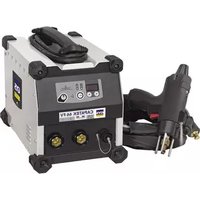
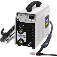
MACHINE SUPPLIED WITH
| MULTIWELD 160M M 013612 066595 | ULTIWELD 200M | |
 | [XOWZ] | [ZCK] |
 |  |  |
 | [6ZZC] | [ZOTD] |
The accessories supplied with the MULTIWELD generator may only be used with this product.
POWER SUPPLY
The MULTIWELD is supplied with a 16A plug type CEE7/7 and must be connected to a 230V single phase power supply (50-60 Hz) with three earthed wires.
The absorbed effective current (I1eff) is displayed on the machine, for optimal use. Check that the power supply and its protection (fuse and/or circuit breaker) are compatible with the current needed by the machine. In some countries, it may be necessary to change the plug to allow the use at maximum settings.
While under intensive use (superior to the duty cycle) the thermal protection can activate, in that case, the arc switches off and the thermal protection indicator switches on.
CONNECTION ON A GENERATOR
The machine can work with generators as long as the auxiliary power matches these requirements :
- The voltage must be AC, always set as specified, and the peak voltage below 400V,
- The frequency must be between 50 and 60 Hz.
It is imperative to check these requirements as several generators generate high voltage peaks that can damage these machines.
USE WITH EXTENSION CABLES
All extension cables must have an adequate size and section, relative to the machine's voltage.
Use an extension that complies with national safety regulations.
| Input Voltage Section of extension cable | |
| MULTIWELD 160M | 230 V - 1~ 1.5 mm^2 |
| MULTIWELD 200M | 230 V - 1~ 2.5 mm^2 |
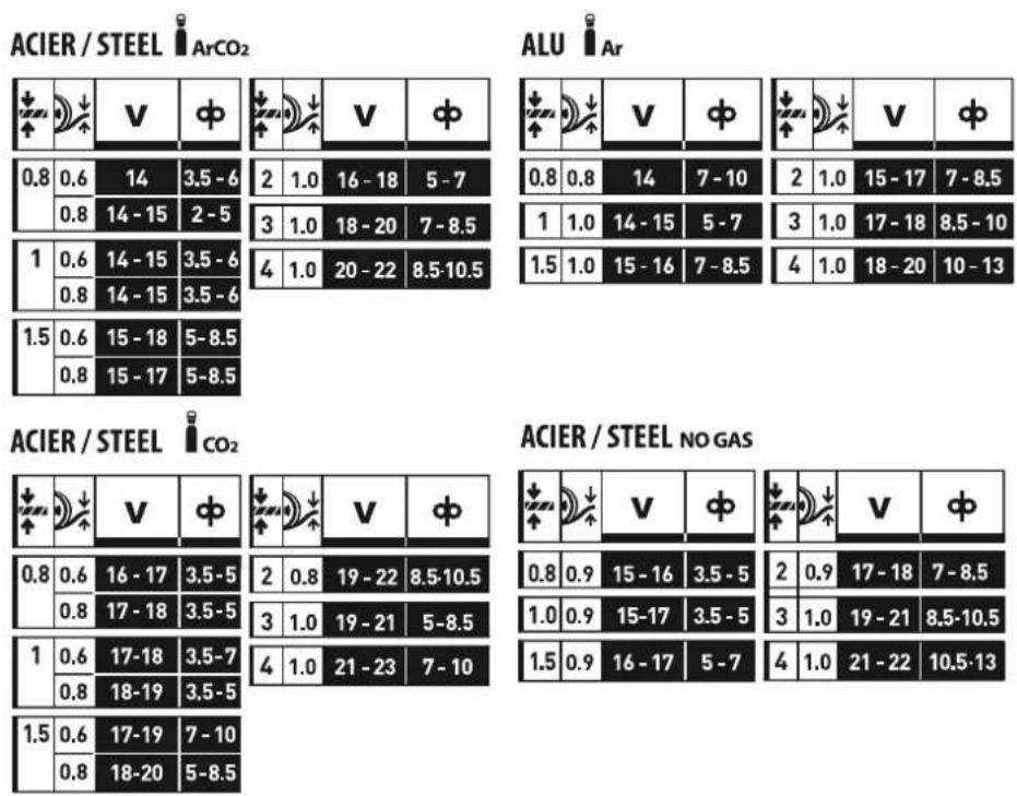
DEVICE PRESENTATION (FIG. I)
1- Reel support 8- Torch support
2- Back cable support 9- Gas connector
3- Digital displays 10- On/off switch
4- Adjustment of welding settings 11- Power supply cable
5- European standard torch connection 12- Bottle support (max 1 x 4m ^3 bottles)
6- Polarity reversal cable 13- Plug 36V AC for gas preheater
7- Earth clamp connector 14- Storage area
15- Switch MIG/ MMA
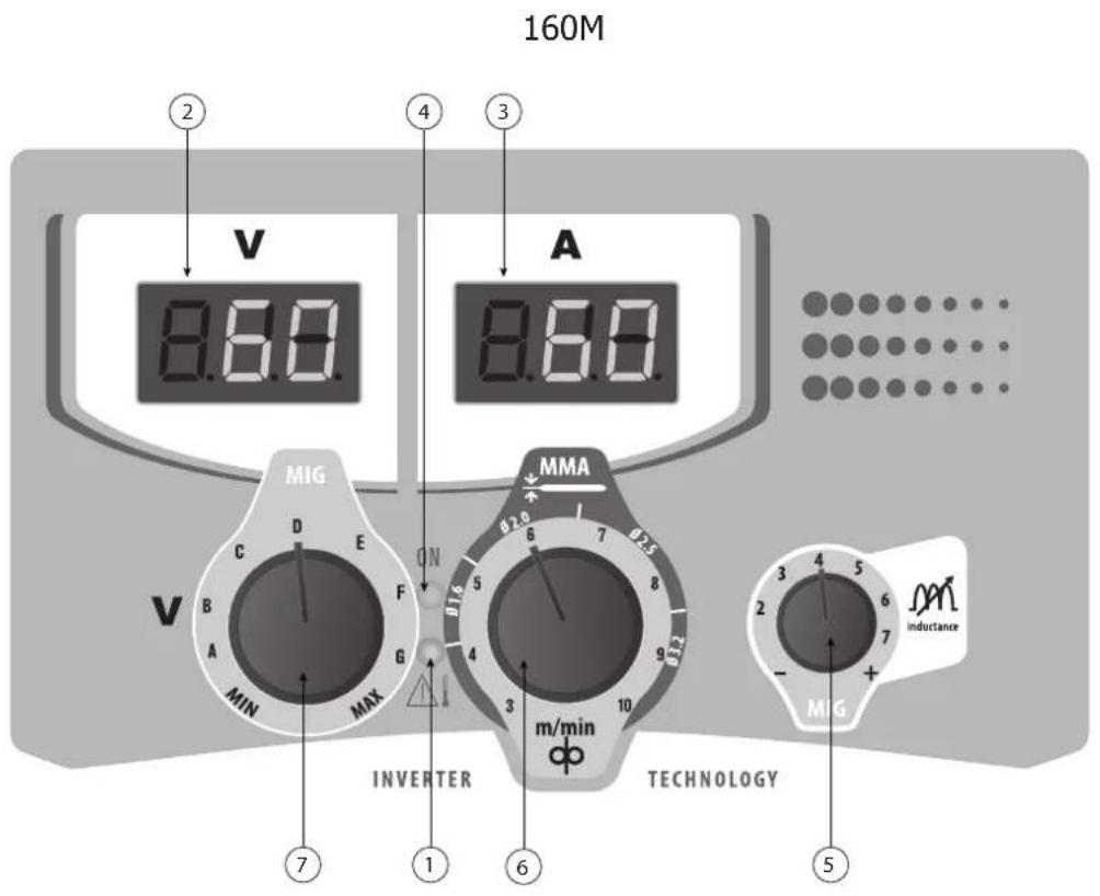
INTERFACE PANEL (FIG. VI)
1- Overheat/Overcurrent indicator
2- Voltage display
3- Current display 7- Voltage setting adjustment
4- Green light «ON»
5- Welding arc dynamic adjustment
6- Wire speed adjustment (MIG) / Current setting adjustment (MMA)
SWITCHING ON
The ON/OFF switch is located at the back of the machine. Press the switch on the «I» position to start the generator. This switch must not be turned off (to «O») while welding. When the machine is powered, the ON LED lights up (FIG VI - 4).
SEMI-AUTOMATIC FOR STEEL/STAINLESS STEEL (MAG MODE)
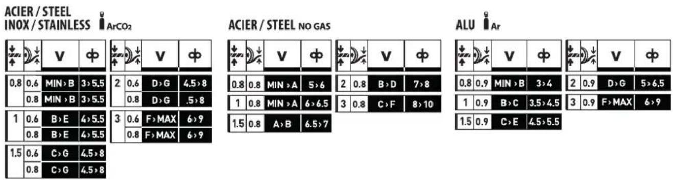
Set the voltage output and the wire speed according to the thickness of the weld piece, following the instructions/ recommendations printed on the front of the machine (fig. VII).
The MULTIWELD 160M can weld Steel wire 0.6/0.8 mm, and Stainless Steel of 0.8 mm.
The MULTIWELD 200M can weld Steel wire 0.6/1.0 mm, and Stainless Steel of 0.8/1.0 mm.
The products are fitted to work with 0.8 mm steel wire (roller ∅ 0.8/1.0). The contact tube, the groove of the roller and the sleeve of the torch are all compatible with 0.8 mm wire. Should you wish to weld 0.6 wire, use a torch of maximum 3 m long. The contact tip must be changed (fig. IV-D) as well as the wire feeder's roller (fig. IV-B) that must be replaced by an optional reference (042339) with a 0.6 diameter groove. In this case, the position in such a way to observe 0.6.
For use with Steel, the gas recommendation is argon + CO2. (Ar+CO2). The proportion of CO2 required will vary depending on the use. For Stainless Steel, use the combination of 2% CO2. If welding using pure CO2 protection gas, you should connect a gas preheater on the gas bottle (Gys reference 046511 for a 230 V version). You may also use a standard 36 V preheater module that can be connected to the 36V power supply plug located nearby the soldering wire reel behind the lateral door (fig. I-13). For other specific gas requirements, please contact your gas distributor. The gas flow in steel is between 8 and 12 liters / minute depending on the environment.
SEMI-AUTOMATIC WELDING FOR ALUMINIUM (MIG MODE)
Set the voltage output and the wire speed according to the thickness of the weld piece, following the instructions/ recommendations printed on the front of the machine (fig. VII).
The MULTIWELD 160M/200M can be equipped to weld with aluminium wire ∅ 0.8 and 1.0 mm.
For use with aluminium, the gas requirement is pure argon (Ar). For the specific gas requirements please contact your distributor. The gas flow in Aluminium is between 15 and 25 Litres/minute depending on the environment, and the experience of the welder. Below are the differences between welding with Steel and Aluminium :
- Specific rollers are needed for welding with Aluminium.
- Adjust the pressure of the drive rolls to prevent the wire being crushed.
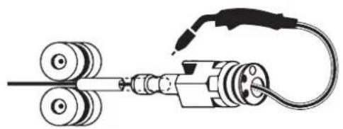
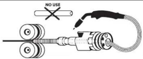
- Use the capillary tube (designed to guide the wire between the wire feeder and the EURO connector) only when welding steel or stainless steel (fig. II).
- Use a special Aluminium Torch with a teflon sheath to reduce friction.
DO NOT cut the sheath close to the joint, it is used to guide the wire from the the rollers. - Contact Tube : Use a special aluminium contact tube specific to the diameter of wire being used.
GASLESS WIRE WELDING
Set the voltage output and the wire speed according to the thickness of the weld piece, following the instructions/ recommendations printed on the front of the machine (fig VII).
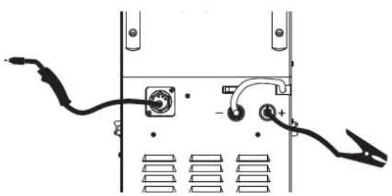
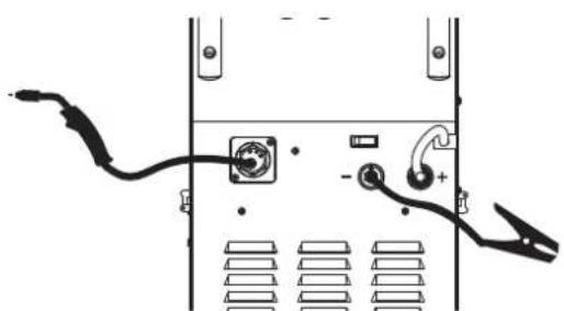
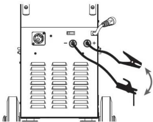
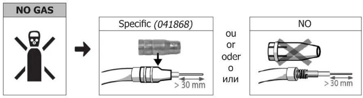
The MULTIWELD 160M/200M can weld gasless wire to 0.9 mm, if the polarity is reversed (fig. III) respecting a maximum pressure of 5Nm. For parameters of use, please refer to the instructions indicated on page 81. Welding gasless wire with a standard nozzle can lead to overheating and deterioration of the torch. It is recommended to use a "No Gas" nozzle (ref. 041868), or remove the genuine nozzle (fig. III).
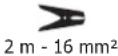
MIG / MAG SETTINGS PANEL
CONNECTION AND RECOMMENDATIONS
- Connect the earth clamp on the positive (+) or negative (-) terminal depending on the wire type (in general on the -).
MODE SELECTION AND SETTINGS
Press the switch (FIG I - 15) to select the welding mode MIG/MAG.
1. Setting the welding voltage :
Adjust the welding voltage using the voltage setting knob depending on the work to be carried out. The voltage setpoint is indicated on the left side display.
2. Setting the wire speed :
Adjust the wire speed using the central knob depending on the work to be carried out.
2. Inductance settings :
Adjust the inductance level using the inductance setting knob, a relative value from MIN to MAX. The lower the inductance level, the harder and more guiding the arc. The higher the inductance and the softer the arc with little splatter.
text_image
V 860 A 60 V MIN MAX GK INVERTER M/Min TECHNOLOGY M/G Mg Min MaxThe black areas are not useful for this mode.
Set the voltage output and the wire speed according to the thickness of the weld piece, following the instructions/recommendations printed on the front of the machine (fig VII).
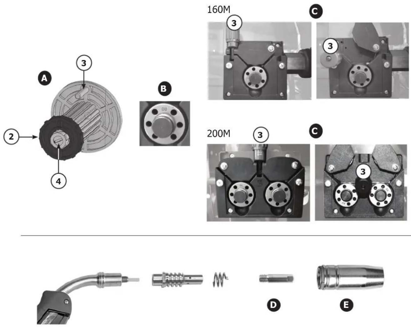
REEL AND TORCH ASSEMBLY (FIG. IV)
This product takes ∅ 200/300 mm wire reel (ecological).
- Remove the contact tube and its support (fig. D), and the nozzle (fig. E) from the torch.
Fig A :
- Open the door of the machine.
- Place the reel on the drive pin (3) of the reel support.
- Adjust the reel brake (4) to avoid reel movement tangling the wire when the welding stops. Be careful not to tighten too much - the reel must rotate without straining the motor.
Fig B :
The drive rolls supplied have two grooves (0.8 V shape groove and 0.9 groove with teeth):
- For 0.8mm steel wire, use the 0.8 V shape groove.
- For corred wire, turn the drive roll over and use the 0.9 mm groove with teeth.
- For 0.8mm aluminium wire, remove and replace the roll with a model specifically designed for aluminium with a U shaped groove (not included).
Fig C :
To select the adjustment of the drive rollers.
- Loosen the drive roller knob (3) as far as possible and insert the wire, tighten the knob again slightly.
- Start the motor by pressing the trigger of the torch.
- Tighten the knob whilst pressing the trigger until the wire starts to move.
ATTENTION: When welding with Aluminium, use the minimum possible pressure to avoid crushing the wire.
- Leave about 5cm of wire out of the torch, then put the contact tube (fig. D), and the nozzle (fig. E) adapted to the wire to be used at the extremity.
GAS CONNECTION
- Connect the manometer (flowmeter) to the gas bottle if needed, then connect the gas hose to the gas connector. To avoid gas leak, use collars supplied in the accessories box.
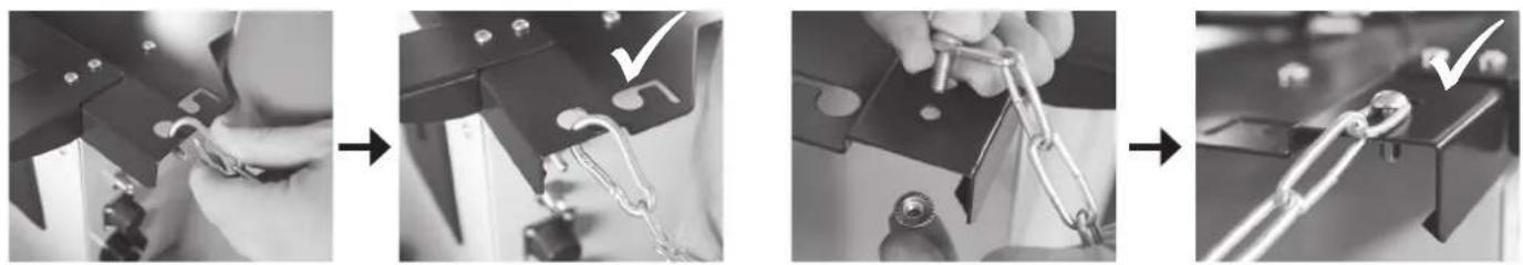
- Make sure the gas bottle hold in place respecting chain fastening cf. fig. V.
- Set the gas flow by adjusting the dial located on the pressure regulator.
NB : to help facilitate the adjustment of the gas flow, operate the drive rollers by pressing the trigger of the torch (ensure that the drive roller is completely loose so the wire is not fed through). Maximum gas pressure 0.5 MPa (5 bars). This procedure does not apply to «Gasless» welding mode.
RECOMMENDED COMBINATIONS
| (mm) | Current (A) ∅ Wire (mm) ∅ Nozzle (mm) Flow rate | L/min | ||
| MIG | 0.8-2 20-100 0 | 8 12 10-12 | ||
| 2-4 100-200 1 | 0 12-15 12-15 | |||
| 4-8 200-300 1 | 0/1.2 15-16 15-18 | |||
| 8-15 300-500 1 | 1.2/1.6 | 16 18-25 | ||
| MAG | 0.6-1.5 15-80 0 | 6 12 | 8-10 | |
| 1.5-3 80-150 0 | 8 12-15 10-12 | |||
| 3-8 150-300 1 | 0/1.2 15-16 12-15 | |||
| 8-20 300-500 1 | 1.2/1.6 | 16 15-18 |
RISK OF INJURY DUE TO MOVING PARTS

The wire feeders contain moving parts that may catch hand, hair, clothes or tools which can lead to injuries! Take extra care.
- Do not lay a hand to swivel or moving components or parts to the drive!
- Ensure that the housing covers or protective covers remain closed during operation!
- Do not wear gloves when feeding the wire through or changing reel.
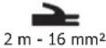
MMA SETTINGS PANEL
CONNECTIONS AND RECOMMENDATIONS
- Connect the cables, electrode holder and earth clamp in the connectors,
- Respect the welding polarities and intensities indicated on the electrodes boxes,
- Remove the electrode from the electrode holder when the machine is not in use.
MODE SELECTION AND SETTING
Press the switch I (FIG I - 15) to select the mode MMA.
Setting the welding current :
Adjust the welding current using the central knob depending on the work to be carried out. The current setpoint is indicated on the central side display.
text_image
V 60 A 860 MMA INVERTER TECHNOLOGYThe black areas are not useful for this mode.
WELDING CURRENT SETTINGS
The following settings concern the current range that may be used depending on the electrode's type and diameter. These ranges are quite large as they depend on the application and the welding position.
| 160M | ∅ electrode (mm) | Rutile E6013 (A) | Basic E7018 (A) |
| 1.6 30-60 30-55 | |||
| 2.0 50-70 50-80 | |||
| 2.5 60-100 80-110 | |||
| 3.2 80-150 90-140 |
| 200M | electrode (mm) | Rutile E6013 (A) | Basic E7018 (A) |
| 1.6 30-60 30-55 | |||
| 2.0 50-70 50-80 | |||
| 2.5 60-100 80-110 | |||
| 3.2 80-150 90-140 | |||
| 4.0 100-200 125-210 |
ELECTRODE WELDING
- The reverse polarity cable must be disconnected in MMA (stick welding) mode in order to connect the electrode holder and earth clamp. Connect the electrode holder and earth clamp as indicated on the electrode packaging.
- Respect the basic rules of welding.
- This device has 1 feature specific to Inverter machines :
- Anti-Sticking: Enables easy removal of the electrode from the metal. The anti-sticking feature, after its start, requires approximately a 3 seconds delay before resuming normal welding operations.
ADVICE & THERMAL PROTECTION
This device is equipped with a ventilator regulated by the inside temperature. When the machine's thermal protection is activated, it will not deliver any current. Yellow light (fig. VI-1) will turn on until the temperature of the machine has returned to normal.
- Do not block/cover the ventilation holes, ensure free flow of air.
- Whilst in thermal protection mode leave the machine plugged into the mains after welding to allow it to cool.
General observations :
• Always respect the basic rules of welding.
• Always work in an adequately ventilated area. - Do not work on a damp surface.
- In order to avoid gas leak, use collarleak, use collars supplied in the accessories box.
- Make sure the gas bottle hold in place respecting chain fastening cf. fig. V.
- Set the gas flow by adjusting the dial located on the pressure regulator.
TROUBLESHOOTING
| SYMPTOMS POSSIBLE CAUS$ES REMEDIES | ||
| The welding wire speed is not constant. | Debris is blocking up the opening. | Clean out the contact batch or change it and replace the anti-adherence product. Ref. 041806. |
| The wire skids in the rollers. | • Control the roller pressure or replace it.• Wire diameter non-compatible with roller.• Covering wire guide in the torch non-compatible. | |
| The wire-feeder motor doesn't operate. | Reel or roller brake too tight. Release the brake and rollers. | |
| Electrical supply problem. | Check that the power switch is in the «On» position. | |
| Bad wire feeding. | Covering wire guide dirty or damaged. Clean or replace | |
| The drive roller is too loose Tighten the drive roller knob | ||
| Reel brake too tight Release the brake | ||
| No welding current | Bad connection to the main supply | Check the mains connection and look if the plug is fed by 230 V (1PH) power socket. |
| Bad earth connection. | Check the earth cable (connection and clamp condition). | |
| Torch trigger inoperative. Check the torch trigger / replace torch | ||
| The wire jams (after the rollers) | Guide wire sheath crushed. Check the sheath and torch body. | |
| Wire jammed in the torch Clean or replace. | ||
| No capillary tube. Check the presence of capillary tube. | ||
| Wire speed too fast Reduce the wire speed | ||
| The welding bead is porous | The gas flow rate is not sufficient. | Adjust flow range 15 to 20 L / min. |
| Clean the working metal. | ||
| Gas bottle empty. Replace it. | ||
| Gas quality unsatisfactory. Replace it. | ||
| Air flow or wind influence. Prevent drafts, protect welding area. | ||
| Gas nozzle dirty. Clean or replace the gas nozzle. | ||
| Poor quality wire. Use suitable WIRE for MIG-MAG welding. | ||
| Surface to weld in bad condition. (rust, etc...) | Clean the metal before welding. | |
| Very important flashing particules. | Arc voltage too low or too high. See welding settings. | |
| Bad earth connection. | Adjust the earth cable for a better connection. | |
| Insufficient gas flow. Adjust the gas flow. | ||
| No gas flow at the end of the torch. | Bad gas connection. | Check the gas connection at the welding machine.Check the gas regulator and the solenoid valves. |
WARRANTY
The warranty covers faulty workmanship for 2 years from the date of purchase (parts and labour).
The warranty does not cover:
- Transit damage.
- Normal wear of parts (eg. : cables, clamps, etc..).
- Damages due to misuse (power supply error, dropping of equipment, disassembling).
- Environment related failures (pollution, rust, dust).
In case of failure, return the unit to your distributor together with:
- The proof of purchase (receipt etc ...)
- A description of the fault reported

WAARSCHUWINGEN - VEILIGHEIDSINSTRUCTIES
ALGEMENE INSTRUCTIES

BESCHRIJVING VAN HET APPARAAT (FIG. I)
MAN MACHINE INTERACTION (MMI) (FIG. VI)
INTERFACCIA UOMO MACCHINA (IHM) (FIG. VI)
text_image
V 860 A 50 V MIN MAX E F G H I J K L M N O P Q R S T U V INVERTER m/min φ TECHNOLOGYRYZYKO POŻARU I WYBUCHU

WYBÓR TRYBU I USTAWIENIE
WYBÓR TRYBU I USTAWIENIE
text_image
Technical diagram of a wheeled cart with numbered parts and directional arrows indicating componentsII
A Acier - Steel - Stahl - Acero - Staal - Aço - Stal
natural_image
Mechanical assembly diagram showing a shaft connected to a cylindrical component with attached cable (no text or symbols)B Aluminium
text_image
NO USEMIG-MAG
natural_image
Diagram of a computer monitor rear panel with cable and indicator lights (no text or symbols)
NO GAS GAS
natural_image
Diagram of a computer rear panel with cable and connectors, no text or symbols present
MMA
FR - Vérifier la polarité de l'électrode sur l'emballage.
EN - Check the electrode polarity on the packaging.
DE - Beachten Sie die auf der Elektrodenverpackung beschriebenen Angaben zur Polarität.
ES - Compruebe la polaridad del electrodo sobre el embalaje.
RU - Проверить полярность электрода на упаковке.
NL - Controleer de polariteit van de elektrode aangegeven op de verpakking.
IT - Verificare la polarità dell'elettrodo sulla confezione.
PL - Sprawdzić polaryzację elektrody na opakowaniu.
natural_image
Diagram of a server rack with connectors and ventilation slots, showing cable routing (no text or symbols)III
text_image
NO GAS → Specific (041868) ou or oder o или NO >30 mm >30 mmIV
text_image
160M 3 3 200M 3 3 D EV
natural_image
Four-panel sequence showing a hand holding a spring, chain link, metal hook, and chain clamp (no text or symbols)VI
text_image
160M V 8.8.8 A 8.8.8 MIG ON MMA V MIN MAX INVERTER m/min TECHNOLOGY 3 4 5 6 2 7 - + - MIG inductance ② ④ ③ ⑦ ① ⑥200M

text_image
V 8.8.0 A 8.8.0 MIG ON MMA MIN MAX INVERTER m/min TECHNOLOGY 3 4 5 6 2 7 10 11 12 13 2 3 4 5 6 - + - MG inductance ② ④ ③ ⑦ ① ⑥ ⑤VII
160M
200M
PIÈCES DE RECHANGE / SPARE PARTS / ERSATZTEILE / PIEZAS DE REPUESTO / ЗАПЧАСТИ / RESERVE ONDERDELEN / PEZZI DI RICAMBIO / CZĘŚCI ZAMIENNE
text_image
Technical diagram of a mechanical device with numbered components and a 200M scale indicator.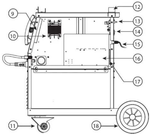
text_image
Technical diagram of a mechanical device with numbered components and directional arrows indicating assembly or flow.| 160M 200M | |||
| 1 | Prise de réchauffeur de gaz / GAS Heating Socket / Toma de calentador de gas / Гнездо подогревателя газа / Stekker gasverwarmer / Presa di riscaldamento del gas / Gasvorwärmeranschluss / Gniazdo podgrzewacza gazu | C21355 | |
| 2 | Porte-fusible / Fuse Holder / Porta-fusibles / Патрон плавкого предохранителя / Zekeringhouder / Porta-fusibile / Sicherungshalter / Uchwyt bezpiecznika | C13707 | |
| 3 | Support de bobine de fil / Wire Reel Support / Soporte bobina de hilo / Держатель бобины / Spoelhouder / Sup- porto bobina del filo / Halterung der Drahtspule / Wspornik szpuli drutu | 71503 | |
| 4 | Support de torche / Torch support / Soporte de antorcha / Подставка для горелки / Toortshouder / Supporto torcia / Brennerhalterung / Wspornik palnika | B31715 | |
| 5 | Poignées / Handles / Mangos / Ручки / Handvaten / Impugnature / Griffe / Uchwyty | 56047 | |
| 6 | Moto-dévidoir / Wire feeder / Motodevanadera / Моторизированный подающий механизм / Draadaanvoer- systeem / Trainafilo / Drahtvorschubmotor / Podajnik drutu | 53530 C51 | 563 |
| 7 | Câble d'inversion de polarité / Polarity invertion cable / Cable de inversión de polaridad / Кабель инверсии полярности / Polariteit inversie kabel / Cavo d'inversione di polarità / Polaritätswahlkabel / Kabel odwracający biegunowość | 71918 B31 | 58 |
| 8 | Connecteur Texas / Texas Connector / Conector Texas / Разъем Texas / Texas koppeling / Connettore Texas / Texas-Stecker / Złącze texas | C31312 | |
| 9 | Carte d'affichage / Display PCBA / Tarjeta de vídeo / Плата индикации / Videokaart / Scheda video / Display-Pla- tine / Karta graficzna | B4024 | |
| 10 | Transformateur auxiliaire / Auxiliary Transformer / Hilfstransformator / Transformador auxiliar / Трансформаторный ассистент / Hulptransformator / Trasformatore ausiliario / Transformator dodatkowy | B2031 | |
| 11 | Roues avant / Front wheels / Ruedas delanteras / Передние колеса / Voorste wielen / Ruote anteriori / Vorderrä- der / Przednie koło | 71361 | |
| 12 | Support de câble arrière / Rear Cable Support / Soporta de cable trasero / Задняя подставка для кабеля / Hulp- transformator / Trasformatore ausiliario / Kabelhalterung hinten / Tylny wspornik kabla | B31717 | |
| 13 | Electrovanne / Solenoid valve / Electroválvula / Электроклапан / Magneetventiel / Elettrovalvola / Elektromagne- tisches Ventil / Zawór elektromagnetyczny | 71540 | |
| 14 | Interrupteur /Switch / An/ Aus- Schalter /Interruptor / Переключатель / Schakelaar / Interruttore / Schakelaar / Wyłącznik | 53546 C51 | 524 |
| 15 | Câble d'alimentation / Power Cable / Cable de alimentación eléctrica / Шнур питания / Voedingskabel / Cavo di alimentazione / Netzleitung / Kabel zasilania | 21468 C51 | 155 |
| 16 | Carte principale / Main circuit board / Hauptplatine / Tarjeta principal / Основная плата / Hoofd printplaat Carta principale / Płyta główna | 53497 B41 | 35 |
| 17 | Ventilateur / Fan / Ventilator / Ventilador / Вентилятор / Ventilator / Ventilatore / Ventilator / Wentylator | 51021 | C16541 |
| 18 | Roue diamètre 200mm / 200mm diameter wheels / 200mm Durchmesser Rad / Rueda diámetro 200mm / Колесо диаметром 200 mm / Wiel 200mm diameter / Średnica koła 200 mm | 71357 | |
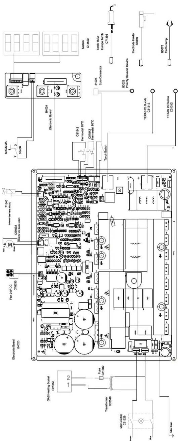
SCHÉMA ÉLECTRIQUE / CIRCUIT DIAGRAM / SCHALTPLAN / DIAGRAMA ELECTRICO / ЭЛЕКТРИЧЕСКАЯ СХЕМА / ELEKTRISCHE SCHEMA / SCEMA ELETTRICO / SCHEMAT ELEKTRYCZNY
text_image
Electronic Board B4025 Fan 24V DC C16535 Red M Green Solenoid Gas Valve 24V DC 71540 Motor for wire heater system MIG/MMA 2 3 52486 Electronic Board GAS Heating Socket C21355 N Transformer C32546 Fuse C51382 Main switch C51529 Yellow Green C51542 thermostat 90°C C51542 thermostat 90°C C51542 Thorch Switch 2D Torch B3028 Polarity Reverse Device B3076 Earth clamp Meters C13620 Torch 150A Europe Torch C71396 TEXAS 25 Buckle C31312 TEXAS 25 Buckle C31312160M
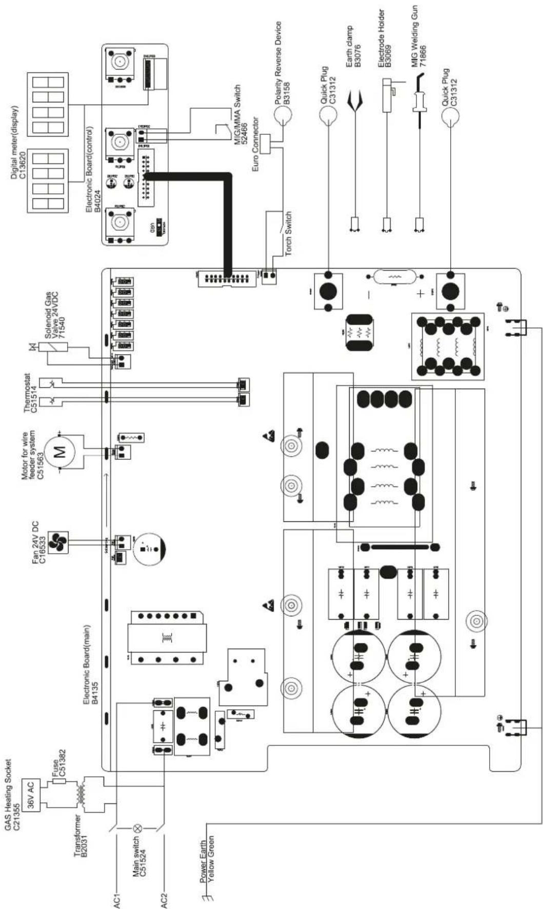
SCHÉMA ÉLECTRIQUE / CIRCUIT DIAGRAM / SCHALTPLAN / DIAGRAMA ELECTRICO / ЭЛЕКТРИЧЕСКАЯ СХЕМА / ELEKTRISCHE SCHEMA / SCEMA ELETTRICO / SCHEMAT ELEKTRYCZNY
text_image
GAS Heating Socket C21355 36V AC Fuse C51382 Transformer B2031 AC1 Main switch C51524 AC2 Power Earth Yellow Green Electronic Board(main) B4135 Fan 24V DC C16533 Motor for wire feeder system C51563 Thermostat C51514 M Solenoid Gas Valve 24VDC 71540 Digital meter(display) C13620 Electronic Board(control) B4024 MIG/MMA Switch 52466 Euro Connector Polarity Reverse Device B3158 Torch Switch Quick Plug C31312 Earth clamp B3076 Electrode Holder B3069 MIG Welding Gun 71866 Quick Plug C31312SPÉCIFICATIONS TECHNIQUES / TECHNICAL SPECIFICATIONS / TECHNISCHE DATEN / ESPECIFICACIONES TÉCNICAS / TEXНИЧЕСКИЕ СПЕЦИФИКАЦИИ / TECHNISCHE GEGEVENS / SPECIFICHE TECNICHE / DANE TECHNICZNE
| 160M 200M | ||||
| Primaire / Primary / Primär / Primario / Первичka / Primario / Primaire / Podstawowy | ||||
| Tension d'alimentation / Power supply voltage / Stromversorgung / Tensione di alimentazione / Напряжение питания / Tensión de red eléctrica / Voedingsspanning / Napięcie zasilania | 230 V +/- 15% | |||
| Fréquence secteur / Mains frequency / Netzfrequenz / Frequenza settore / Частота сети / Frecuencia / Frequentie sector / Częstotliwość sieci zasilania | 50 / 60 Hz | |||
| Fusible disjoncteur / Fuse / Sicherung / Fusibile / Плавкий предохранитель / Fusible / Zekering / Wyłącznik bezpieczników | 16 A | |||
| Courant d'alimentation effectif maximal I1eff / Maximum effective supply current I1eff / Corriente de alimentación efectiva máxima I1eff / Maximale effectieve voedingsstroom I1eff / Corrente di alimentazione effettiva massima I1eff / Maksymalny efektywny prąd zasilania I1ef | 12.5 A 16 A | |||
| Courant d'alimentation maximal I1max / Maximum supply current I1max / Corriente de alimentación máxima I1max / Maximale voedingsstroom I1max / Corrente di alimentazione massima I1max / Maksymalny prąd zasilania I1max | 28 A 41 A | |||
| Section du cordon secteur / Mains cable section / Sectile netsnoer / Sección del cable de alimentación / Sezione del cavo di alimentazione / Odcinek przewodu zasilającego | 3 x 1.5 mm2 3 x 2.5 m2 | |||
| Puissance active maximale consommée / Maximum active power consumed / Consumo máximo de energía activa / Maximale actieve verbruikte vermogen / Potenza attiva massima consumata / Maksymalny pobór mocy czynnej | 4.2 kW 6.2 kW | |||
| Consommation au ralenti / Idle consumption / Consumo en ralentizado / Stationair verbruik / Consumo al minimo / Zużycie na biegu jałowym | 22 W 22 W | |||
| Rendement à I2max / Efficiency at I2max / Eficiencia a I2max / Rendement bij I2max / Efficienza a I2max / Sprawność przy I2max | 84 % 83 % | |||
| Facteur de puissance à I2max (λ) / Power factor at I2max (λ) / Factor de potencia a I2max (λ) / Inschakelduur bij I2max (λ) / Ciclo di potenza a I2max (λ) / Współczynnik mocy przy I2max (λ) | 0.58 0.62 | |||
| Classe CEM / EMC class / Classe CEM / Klasse CEM / Klasse EMC A | ||||
| Secondaire / Secondary / Sekundár / Secondario / Вторичка / Secundario / Secondair / Zapasowy | MMA MIG-MAG MMA MIG-MAG | |||
| Tension à vide / No load voltage / Lcerlaufspannung / Tensione a vuoto / Напряжение холостого хода / Tensión al vacío / Nullastspanning / Napięcie próżniowe | 59 V 65 V | |||
| Nature du courant de soudage / Type of welding current / Tipo de corriente de soldadura / Type lasstroom / Tipo di corrente di saldatura / Rodzaj prądu spawania | DC | |||
| Modes de soudage / Welding modes / Modos de soldadura / Lasmodules / Modalità di saldatura / Tryby spawania | MMA, MIG-MAG | |||
| Courant de soudage minimal / Minimum welding current / Corriente mínima de soldadura / Minimale lasstroom / Corrente minima di saldatura / Minimalny prąd spawania | 20 A 30 A | |||
| Courant de sortie nominal (I2) / Normal current output (I2) / nominaler Ausgangsstrom (I2) / Corrente di uscita nominale (I2) / Номинальный выходной ток (I2) / Corriente de salida nominal (I2) / Nominale uitgangsstroom (I2) / Nominalny prąd wyjściowy (I2) | 20 → 140 A 30 | → 160 A | 30 → 180 A | |
| Tension de sortie conventionnelle (U2) / Conventional voltage output (U2) / entsprechende Arbeitsspannung (U2) / Tensione di uscita convenzionale (U2) / Условное выходные напряжения (U2) / Tensión de salida convencional (U2) / Conventionele uitgangsspanning (U2) / Konwencjonalne napięcie wyjściowe (U2) | 20.8 → 25.6 V | 15.5 → 22 V | 21.2 → 27.2 V | |
| Facteur de marche à 40°C (10 min)*Norme EN60974-1.Duty cycle at 40°C (10 min)*Standard EN60974-1.Einschaltdauer @ 40°C (10 min)*EN60974-1 -Norm. | Ciclo de trabajo a 40°C (10 min)*Norma EN60974-1ПВ% при 40°C (10 min)*Норма EN60974-1Ciclo di lavoro a 40°C (10 min)*Norma EN60974-1Cykl pracy w 40°C (10 min)*Norma EN60974-1. | Imax | 20 % 15 % | |
| 100% | 70 A | 75 A | ||
| 60% | 90 A | 95 A | ||
| Diamètre minimal et maximal du fil d'apport / Minimum and maximum diameter of filler wire / Minimaler und maximaler Durchmesser des Schweilfülldrahtes / Diâmetro mínimo y máximo del hilo de soldadura / Минимальный и максимальный диаметр присадочной проволоки / Minimale en maximale diameter van het lasdraad / Diâmetro mínimo e massimo del filo d'apporto | Acier / Steel | 0.6 → 0.8 mm | 0.6 → 1.0 mm | |
| Inox / Stainless | 0.8 mm | 0.8 mm → 1.0 mm | ||
| Aluminium | 0.8 → 1.0 mm | 0.8 → 1.0 mm | ||
| Fil fourré / Corcd | 0.9 mm | 0.9 mm | ||
| Connectique de torche / Torch connector / Brenneranschluss / Conexiones de antorcha / Соединения горелки / Aansluiting toorts / Connettori della torcia | EURO | |||
| Type de galet / Drive roller type / Drahtführungsrolle-Typ / Tipo de rodillo / Тип ролика / Type draadaanvoerrol / Tipo di rullo | A | |||
| Vitesse de dévidage / Motor speed / Motor-Drehzahl / Velocidad de motor / Скорость двигателя / Snelheid motor / Velocità del motore | 3 → 10 m/min | 2 → 13 m/min | ||
| Puissance du moteur / Motor power / Leistung des Motors / Potencia del motor / Vermogen van de motor / Potenza del motore | 40 W | 50 W | ||
| Diamètre maximal de la bobine d'apport / Maximum diameter of the supply reel / Maximaler Durchmesser der Schweilfülldrahtspule / Diâmetro máximo de la bobina de alambre / Максимальный вес проволочной бобины / Maximale diameter van de spoel / Diâmetro massimo della bobina d'apporto | ∅ 300 mm | |||
| Poids maximal de la bobine de fil d'apport / Maximum weight of the filler wire reel / Maximales Gewicht der Schweilfülldrahtspule / Peso máximo de la bobina de alambre / Максимальный вес проволочной бобины / Maximale gewicht van de spoel / Peso massimo della bobina del filo d'apporto | 18 kg | |||
| Pression maximale de gaz (Pmax) / Maximum gas pressure (Pmax) / Maximaler Gasdruck (Pmax) / Presión máxima de gas (Pmax) / Максимальное давление газа (Pmax) / Maximale gasdruk (Pmax) / Pressione massima del gas (Pmax) / Maksymalne ciśnienie gazu (Pmax) | 0.5 MPa (5 bar) | |||
| Température de fonctionnement / Functionning temperature / Betriebstemperatur / Temperatura de funcionamiento / Рабочая температура / Gebruikstemperatuur / Temperatura di funzionamento / Temperatura urządzenia podczas pracy | -10°C → +40°C | |||
| Température de stockage / Storage temperature / Lagertemperatur / Temperatura de almacenaje / Температура хранения / Bewaartemperatuur / Temperatura di stoccaggio / Temperatura przechowywania | -20°C → +55°C | |||
MULTIWELD 160M / 200M
| Degré de protection / Protection level / Schutzart / Grado de protección / Степень защиты / Beschermingsklasse / Grado di protezione / Stopień ochrony | IP21 | |
| Classe d'isolation minimale des enroulements / Minimum coil insulation class / Clase mínima de aislamiento del bobinado / Minimale isolatieklasse omwikkelingen / Classe minima di isolamento degli avvolgimenti / Minimalna klasa izolacji okablowania | B | |
| Dimensions (Lxlxh) / Dimensions (LxWxH) / Abmessungen (Lxbxt) / Dimensiones (Lxlxh) / Размеры (ДхШхВ) / Afmetingen (Lxlxh) / Dimensioni (Lxlxh) / Wymiary (DxSxW) | 77 x 79 x 47 cm | |
| Poids / Weight / Gewicht / Bec / Peso / Gewicht / Peso / Waga 34.2 kg 34.5 kg | ||
*The duty cycles are measured according to standard EN60974-1 à 40°C and on a 10 min cycle.
While under intense use (> to duty cycle) the thermal protection can turn on, which switches the arc off and the indicator switches on.
Keep the machine's supply on, to enable cooling until protection cancellation.
The machine has a specification with a "dropping current output" in MMA and with a "constant current output" in MIG/MAG.