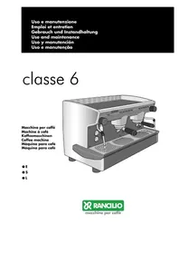
USER MANUAL Classe 6 RANCILIO
natural_image
Illustration of a modern espresso machine with dual levers and control panel (no text or symbols visible)
E
●S
●L

RANCILIO
macchine per caffè

Gentile cliente,
First of all, thank you choosing RANCILIO.
We are confident that the product you have purchased will come up to all your expectations-just as all our other products are designed to do. The product that you are about to use is the outcome of pain-staking research and tests. The Rancilio's consistency assures quite sure that the equipment we have supplied you with, is the most functional, safe and satisfactory of its kind to be found on the market, as regards both its design and its efficiency. The booklet of instructions for its correct use and maintenance will help you to get the best possible service out of your machine. We trust you will find our explanations clear and we may continue, in the future, to count you among our esteemed customers.

EN Treatment of waste from electric/electronic equipment
Dispose of the product in accordance with current regulations concerning differentiated waste disposal in dedicated waste disposal areas.
Do not treat as simple urban waste.
For any information please contact the manufacturer at the address specified in the user manual.
The product complies with the requirements of the new directives introduced for the environmental safeguard and must be disposed of appropriately at the end of its life cycle.
73/23/CEE, 93/68/CEE
89/336/CEE, 93/68/CEE, 92/31/CEE
natural_image
Line drawing of a coffee machine with labeled parts (no text or symbols beyond label)
Fig. 2
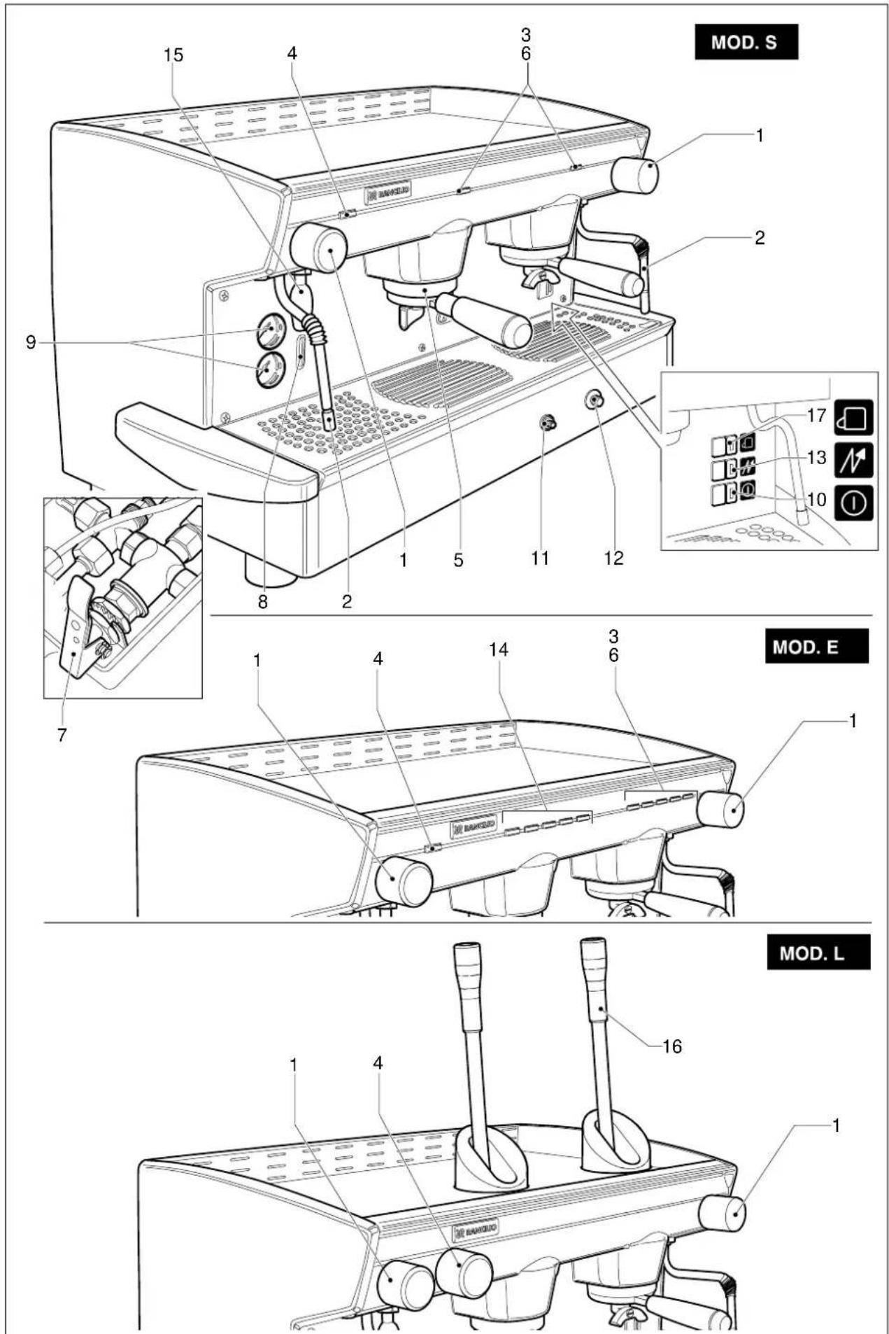
Fig. 3


natural_image
Illustration of hands using a wrench and a wrench to adjust a bolt, with no text or symbols present.
natural_image
Technical line drawings of a coffee machine with two cups on top and a hand inserting into the base panel (no text or symbols)

natural_image
Technical illustration showing a kitchen switch mechanism and a hand holding a tool on a tray (no text or symbols present)
Fig. 7

natural_image
Illustration of a hand pouring liquid into a mug on a machine, with no visible text or symbols.
natural_image
Illustration of a hand holding a tool interacting with a speaker grille (no text or symbols)


natural_image
Line drawing of a coffee machine with a hand pressing down on a grater tray, labeled Fig. 11 (no text or symbols on the diagram itself)

IT ITALIANO 12-23
FR FRANCAIS 24-35
DE DEUTSCH 36-47
EN ENGLISH 48-59
ES ESPAÑOL 60-71
PT PORTUGUÊS 72-83
SCHEMI ELETTRICI 84-90
SCHEMAS ELECTRIQUES
SCHALTPLANE
WIRING DIAGRAMS
ESQUEMAS ELECTRICOS
ESQUEMAS ELÉTRICOS
SCHEMI IDRAULICI 91-93
SCHÉMAS HYDRAULIQUES
HYDRAULIKPLÄNE
HYDRAULIC DIAGRAMS
ESQUEMAS HIDRÁULICOS
ESQUEMAS HIDRÁULICOS
IT ITALIANO
INDICE
13. VERSION MACHINE AVEC CHAUFFAGE D'APPOINT AU GAZ (Fig.14)

HYDRAULIC DIAGRAMS 91-93
ESQUEMAS HIDRÁULICOS
ESQUEMAS HIDRÁULICOS
EN ENGLISH
CONTENTS
Machine identification data ....49
-
General safety rules ....49
-
Description ....50
2.1. Specifications and composition .....50
2.2. Machine equipment 50
2.3. Mechanical protective devices .....51
2.4. Electric safety devices ....51
2.5. Aerial noise 51
2.6. Vibrations .....51
- Technical data ....51
3.1. Dimensions and weights .....51
- Use ....51
4.1. Precautionary measures .....52
- Transport ....52
5.1. Packaging 52
5.2. Inspection on receipt ....52
- Installation ....52
6.1.Connections to be made by the user .....53
6.1.1. Water and gas supply 53
6.1.2. Electric supply ....53
6.2. Preliminary operations .....53
6.3. Lever assembly (Mod.L) .....53
6.4. Connections 53
- Operation ....54
7.1. Controls ....54
7.2. Control instruments .....54
7.3. Starting up ....54
- Use ....55
8.1. Preparing coffee .....55
8.2. Preparing cappuccino .....55
8.3. Warming a beverage 56
8.4. Preparing tea, camomile, etc.... 56
- Adjustments and settings of the dose ....56
9.1.For models E 56
9.1.1. Adjusting the dose 56
9.1.2. Adjusting the quantity of hot water ....57
9.2. Tray case assembly 57
- Maintenance ....57
10.1.Daily 57
10.2.Weekly 57
10.3. Periodical .....58
10.3.1. Renewal of water 58
-
Stopping the machine .....58
-
Troubleshooting ....58
-
Machines with alternative gas heater version ....59

The operations marked with this symbol are to be undertaken exclusively by an installation technician

The operations marked with this symbol are to be undertaken by the user.
NAME: Coffee machine, CLASSE 6 series
MODEL: E-S-L
VERSIONS: 1 - 2 - 3 - 4 GROUPS (L)
2 - 2 COMPACT - 3 GROUPS (E - S)
The label illustrated on the EC Declaration of Conformity of this instruction manual corresponds to the identification label placed on the machine Fig. 2. (Pos. A).
Label identification (Fig.1):
1 Manufacturer
2 Model and version
3 Voltage
4 EC conformity mark (if required)
5 Serial number
6 Boiler data
7 Machine total absorption
8 Protection level
9 Motor power
10 Heating element power
11 Frequency
12 Conformity marks
13 Year of manufacture
Symbols

Warning signal. The instructions which refer to this signal must be followed with great care in order to avoid accidents or damage to the machine.
This manual is an integral and essential part of the product and must be delivered to the user. The warnings contained in it must be read carefully, as they supply important indications relating to the safety of installation, use and maintenance. Keep this manual for future reference.
1. GENERAL SAFETY RULES
- Don't leave the packing elements (plastic bags, expanded polystyrene, nails, cardboard, etc.) within the reach of children, as these elements are potential sources or danger.
- Check that the data on the machine corresponds to that of the electrical supply network, before connecting the equipment.
- Adaptors, multiple sockets and /or extensions must not be used.
- In doubt, request an accurate control of the plant by qualified personnel. The electric plant must be provided with the following safety devices:
- efficient earth connection;
- section of conductors suitable for absorption capacity
- efficient earth leakage protection circuit breaker.
-
Install the machine on a water repellent surface (laminate, steel, ceramic, etc.) away from heat sources (oven, cooking stove, fireplace, etc.) and in conditions in which the temperature may not go below 5°C. KEEP WARM.
-
Do not leave the machine exposed to atmospheric agents or place them in damp rooms such as bathrooms.
- Do not obstruct the suction or dispersion grilles and do not cover with cloths, etc.
- Keep the packed machine in a dry place, not exposed to atmospheric agents and in conditions in which the temperature does not go below 5°C.
Do not stack more than three items of the same kind. Do not place heavy items on the packaging.
- In an emergency, such as the breaking out of a fire, unusual noise, overheating, etc., take immediate action, disconnecting the power and closing gas and water taps.
- Only use original spare parts in order to avoid compromising the safety and proper functioning of the machine.

Erroneous installation can cause damage to people, animals and things for which the manufacturer cannot be considered responsible
2. DESCRIPTION
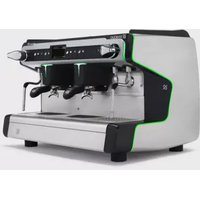
The machines in the CLASSE 6 series have been designed to prepare express coffee and hot beverages.
A positive-displacement pump inside the machine powers the heater in which the water is heated. By pressing the appropriate buttons, water is supplied to the spouts in the form of hot water or steam, according to needs.
The hot water used to make drinks comes from the boiler and is mixed directly with cold water from the water outlet.
The machine is composed of a steel carrying structure on which the mechanical and electrical components are fitted. These are completely covered with panels made of aluminium.
The beverages are dispensed at the front of the machine, where all the buttons, control devices and dispensers are to be found.
There is a cup-warming plate on the top of the machine.
2.1. Specifications and composition (Fig.3)
| A | B | C | D | E |
| E | - | ok | 2 - 3 | 2 | 1 |
| S | ok | - | 2 - 3 | 2 | 1 |
| L | ok | - | 1 - 2 - 3 - 4 | 2 | 1 |
Legend:
A Semiautomatic system; manual dispensing start and stop.
B Automatic system; electronic control of coffee and hot water doses dispensed.
C N. of coffee dispensing units.
D N. of steam spouts.
E N. of hot water spouts.
F Operating with economizer.
Gas heating, on request.
1 Steam tap
2 Steam spout
3 Function/service button panel
4 Hot water switch
5 Coffee dispensing unit
6 Coffee dispensing button panel (mod.S - E)
7 Manual water supply button
8 Level indicator
9 Gauge
10 Power on-off switch and led
11 Gas lighter (on specific models)
12 Valved gas tap (on specific models)
13 Switch and boiler resistance engagement light.
14 Programming panel (mod. E)
15 Hot water spout
16 Dispenser control lever (mod.L)
17 Cup heating resistance switch
2.2. Machine equipment
| 1 GROUP | 2 GR.COMPACT2 GROUP | 3 GROUP | 4 GROUP |
| 1 dose filter holder | 1 1 1 1 | | | |
| 2 dose filter holder | 2 2 3 4 | | | |
| Filters | 3 3 4 5 | | | |
| 1 mt. supply pipe | 1 1 1 1 | | | |
| 1,5 mt. supply pipe | 1 1 1 1 | | | |
| 1,5 mt. drainage pipe | 1 1 1 1 | | | |
| Pipe connections | 1 1 1 1 | | | |
| Blind disks for cleaning | 2 2 3 4 | | | |
| Doser and presser | 1 1 1 1 | | | |
| Instruction manual | 1 1 1 1 | | | |
| Brush | 1 1 1 1 | | | |
| Tray side cases | 1 1 1 1 | | | |
Models equipped with gas connections (when applied).
2.3. Mechanical protective devices
The machine is equipped with the following protective devices:
- complete panelling protection of all the parts subject to heat and of the steam and hot water supplier;
- cup-warmer plate supplied with a tray to collect spilt liquids;
● work surface provided with grill and tray to collect spilt liquids;
● expansion valve in the hydraulic system and valve on the boiler to avoid overpressure;
● nonreturn valve on the hydraulic system to avoid flowing back to the main supply.
2.4. Electric safety devices
The safety devices provided are:
● 12V low tension push buttons an the E control key panel;
● thermal protection on the pump motor;
● gas failure thermocouple and thermocouple thermostat automatically closing gas tap;
● safe resistance thermal;
● Electronic safety devices.
2.5. Aerial noise
Noise level in the working place does not usually exceed 70dB(A).
2.6. Vibrations
The machine is supplied with rubber vibration damping feet. In normal working conditions, the machine does not produce vibrations harmful to the operator and the environment.
3. TECHNICAL DATA
3.1. Dimensions and weights (Fig.4)
| 1 GROUP | 2 GR. COMPACT | 2 GROUP 3 GROUP 4 GROUP |
| A mm | 690 690 850 1090 1330 |
| A1* mm | 570 570 730 970 1210 |
| B mm | 505 505 665 905 1145 |
| C mm | 500 500 500 500 500 |
| D mm | 300 300 300 300 300 |
| H mm | 490 490 490 490 490 |
| H1** mm | 850 - 850 850 850 |
| Boiler capacity in litr. | 5 5 11 | 16 | 22 |
| Machine weight kg | 53 | 55 | 76 | 94 | 112 |
| Water inlet | 3/8" | 3/8" | 3/8" | 3/8" | 3/8" |
| ∅mm drainage | 14 | 14 | 14 | 14 | 14 |
| Packaging |
| Volume m3 | 0.28 0.28 0.35 0,45 0,54 |
| Dimensions L x P x H mm | 760x650x605 | 760x650x605 | 880x650x605 | 1120x650x605 | 1360x650x605 |
| Gross weight kg | 63 | 65 | 76 | 90 | 108 |
* A1(reduced overall dimensions with side case assembly)
**H1 (version lever)

You'll find all the technical data on electric connection, on the machine identification label Fig. 1.
Machines provided with gas heating have a standard connection kit to carry out the following connections with:
- direct stiff pipe;
- copper and double cone pipe;
- rubber support.

Gas connections must be made in compliance with the safety regulations in force in the relative country.
4. USE
The machine have been designed, manufactured and protected to be used to make express coffee and hot beverages (tea, cappuccino, etc.). Any other use is to be considered unsuitable and therefore dangerous.

The manufacturer cannot be held responsible for any damage caused to people or things due to unsuitable, erroneous or irrational use of the machine.
The operator must always follow the indications contained in this manual. In the case of a failure or if the machine is not working properly, switch it off and do not attempt any direct repair. Refer exclusively to a service centre.
The user must not:
● touch the hot surfaces and dispensing areas;
● place liquids containers on the machine;
● put his hands under the spouts during use;
● transport the machine or carry out maintenance operations when the plug is connected or when the machine is hot;
● wash the machine with water or steam jet;
● dip completely or partially the machine in water;
● use the machine if the cable is damaged;
● touch the machine when his hands or feet are wet or damp;
● use the machine when there are children in its proximity;
- allow the machine to be used by children or unfit people;
- obstruct the suction or dispersal grilles with cloth or any other thing;
● do not use the machine when wet or very damp.
4.1. Precautionary measures
This machine may only be used with foodstuffs. It cannot be used for heating liquids or grinding any other kind of product that could damage and pollute it.

The manufacturer cannot be held responsible for damage to people or things caused by unsuitable, erroneous or irrational use.
5. TRANSPORT
5.1. Packaging
The machine is delivered in a strong cardboard box with internal protection.
The packaging bears symbols which must be observed during handling and stocking of the item.

Always keep the package in a vertical position during transport. Do not turn it over or lay it on its side and avoid bumping and exposure to atmospheric agents.
5.2. Inspection on receipt
Check that the machine received corresponds to the one indicated on the delivery note, including any accessories.
Check that it has not been damaged during transport and, if so, inform the forwarder and our customer service office immediately.

The packing elements (plastic bags, expanded polystyrene, nails, cardboard, etc.) must not be left within reach of children as they are potential sources of danger. Do not dispose of the packing elements in the environment; consign them to firms authorized for their disposal.

6. INSTALLATION
The appliance is only to be installed in locations where use and maintenance is restricted to trained personnel.
The machines are fitted with height adjustable feet.
The support surface shall be levelled, dry, smooth, steady and stable and at such a height that the cup-warming surface is at over 150 cm from ground. Do not use water jets or install where water jets are used.
In order to guarantee normal operation, the machine must be installed in areas that the environmental temperature is between +5^ ÷ +32^ end humidity of not over 70% .
It does not need to be anchored to the surface and it does not require any technical operations to dampen vibrations in order to operate properly.
It is recommended to leave the area around the machine free to facilitate its use and the performance of any maintenance operations.
If the machine is wet or very damp, wait until it is completely dry before installing or using it. It is always necessary to request an accurate control to qualified service people in order to find any possible damage to the electric components.
Reserve an area near the machine for the installation of the coffee grinding and dosage machine (see relevant documentation).
The machine is usually equipped with a water softener, type DP2 or DP4, which must be connected by the user in compliance with the laws in force.
Should a different softener be installed, refer to the documentation of the relevant product.
A dreg drawer should be fitted by the installer.

6.1. Connections to be made by the user

Hook-up must be carried out by qualified personnel in full accordance with federal, state and local regulations.
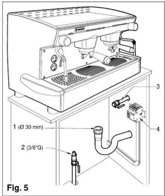
6.1.1. Water and gas supply (Fig.5)

This equipment is to be installed to comply with the applicable federal, state or local plumbing codes.
Connections must be installed close to the machine.
● Water drainage pipe 1, having a minimum internal diameter of 30 mm, equipped with a water-trap accessible for inspection.
● Water supply pipe 2, with a 3/8"G cut-off tap.
● Gas supply pipe 3, with a cutoff tap.

Make sure that the maximum supply pressure does not exceed 6.5 bar; otherwise, install a pressure reducer.

The machine with gas heating must be installed in compliance with current local laws.

6.1.2. Electric supply
The machine is supplied ready for connection according to the required electrical specifications. Before connecting the machine ensure that the plate details comply with those of the electric distribution network.
The electrical connection cable must be directly connected to the connection provided according to current legislation. Ensure that the earthing system is efficient and in compliance with current legal requirements.
The earthing system and the lightening protection system must be realized in accordance with the provisions of current legislation.
For the supply network use a cable in compliance with standards with protective conductor (earthing wire).
For three-phase power use a cable with 3 conductors (3 phases + neutral + earth).
For single phase power supply use a cable with 3 conductors (phase + neutral + earth).
In both cases it is necessary to provide an automatic differential switch (Fig.5) at the start of the power cable, complete with magnetic release elements in accordance with the identification plate details (Fig. 1). The contacts must have an opening of equal or over 3 mm and with dispersed current protection of 30 mA.
Remember that each machine must be fitted with its own safety elements.

WARNING:
Should the power supply cable be damaged it is to be replaced by the manufacturer or by its technical assistance service or by person with equivalent qualification, in order to prevent any risks.

6.2. Preliminary operations (Fig.6)
POTENTIAL-EQUALIZING CONNECTION
This connection, which is the one called for by several norms, avoids electrical potential differences, building up between any equipment that may be installed in the same room. There is a terminal clip on the under side of the base of the machine to which an external potential-equalizing wire should be connected.
This connection is ABSOLUTELY NECESSARY and must be made right after the machine is installed.
Use a wire whose cross-sectional area conforms to the existing norms.
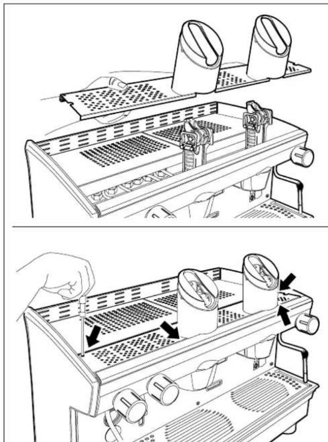
6.3. Lever assembly (Mod.L) (Fig.7)
During the installation, the lever shall be assembled.
To carry out this operation, assemble the upper case according to the instructions in Fig.7 (1 and 2).
Fix the case by tightening the screws and then screw the lever in the upper part.

6.4. Connections
- Place the machine on the horizontal surface previously prepared.
Before connecting, thoroughly wash the mains water pipes:
- Leave the water supply taps running at full pressure for several minutes.
- Connect to the mains water supply.
- Connect the machine to the socket.
- Connect the gas pipe.
Thoroughly wash all the water pipes of the machine:
- Leave the water supply taps running at full pressure.
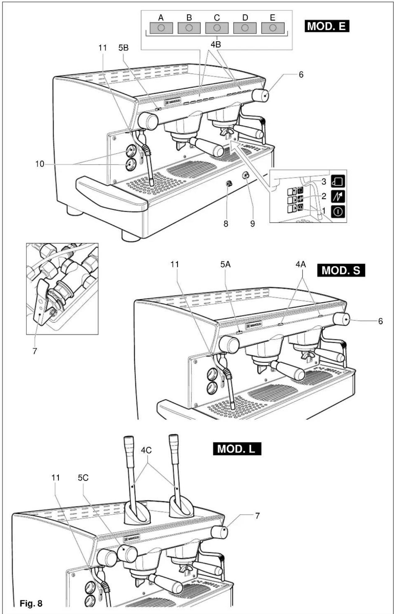
- Switch on main switch 1 (Fig.8): wait until the boiler fills up to the level set.
- Switch on boiler resistance switch 2 (Fig.8) to begin heating the water in the boiler.
- Operate each unit in order to allow the water to escape for about one minute; repeat the operation twice.
- Deliver steam from the steam jets for about one minute.
- Deliver hot water for about one minute; repeat the operation twice.
● Switch off switches 1 and 2.
● Empty the water from the boiler: see point 10.3.1.

IMPORTANT
Should the machine not deliver water for over 24 hours, wash the internal components before beginning work, repeating the operations as described above.
7. OPERATION
7.1. Controls (Fig.8)
1 Main switch
Two-position switch with led.
Turn on the switch (led on) the machine is turned (apart from the boiler) and the pump is turned on to fill the boiler;
2 Boiler resistance switch
Two-position switch with led.
On activating the switch (the led comes on) and power is supplied to the resistance for the boiler water.
3 Cup heating resistance switch
Two-position switch with led.
By turning on the switch (led on), the cup heating resistance is power supplied.
4A Coffee dispensing switch (mod.S)
Two-position switch:
With switch ON, coffee is dispensed;
With switch OFF, dispensing of coffee is interrupted.
4B Coffee Dispensing Electronic Panel (mod. E)
This panel features 5 buttons for each dispenser (max 4) and 5 LEDs consisting of the following:
4 (A-B-C-D) buttons for start/stop dispensing the programmed coffee dose
1 (E) button for:
- Stop dispensing any dose
- Start in continuous mode
- Initialize dose programming for self-learning if pressed for about 8 sec.(If the function is enabled)
Each time a coffee is dispensed, the LED of the relative button lights up.
During dose programming, the LED of the 5 button flashes rapidly.
If the dose is supplied irregularly or the volumetric counter is malfunctioning, the LED of the pressed button flashes dispensing the dose on a time basis.
4C Coffee dispensing control lever (mod.L)
The lever is usually placed in high position.
Activate hte lever by pushing it down to obtain coffee dispensing.
Hot water switch (picking up directly from the boiler) with two positions:
With switch ON, the LED flashes and hot water is dispensed directly from the boiler.
With switch OFF, the LED switches off and dispensing stops.
When the button is pressed, hot water is dispensed directly from the boiler for the set time or until the button is pressed again.
If you press the button for 2 seconds, dispensing is continuous and only stops when the button is pressed again.
Dispensing is discontinued automatically after 30 and 60 seconds, respectively.
5C Hot water supply tap (mod.L)
Tap: turn a anticlockwise to open and clockwise to close.
Safety Devices
Dispensing cannot be carried out if the machine has not reached the operating pressure or temperature at least once, and each time that the boiler pressure drops too much.
6 Steam supply handwheel.
Tap: turn in an anticlockwise direction to open and clockwise to close.
Press down to fill the boiler.
8 Valved gas power tap (models with gas heating).
Open: vertical position;
Closed: turn 90° in clockwise direction.
9 Piezoelectric button (models with gas heating).
Firing button: press down firmly to give off the spark to light the gas for the burner.
7.2. Control instruments (Fig.8)
10 Gauge with mobile needle on a fixed dial with a double scale.
Visual control of the pump (lower manometer) and of the boiler pressure (upper manometer) (mod. E-S).
11 Minimum and maximum water level indicator.
Visual control of water level in boiler.
12 Control window (models with gas heating).
Visual control of lighting and functioning of the flame of the gas burner.


7.3. Starting up
● Turn on the water supply tap 2 Fig.5.
● Turn the main switch 1; the pump is activated, filling the boiler.
- When the water reaches the correct level, the pump stops.
Turn the main switch 2 to begin heating the water in the boiler then turn each one until water begins to flow from them.
- Wait for the machine to reach its working pressure and to reach the correct thermal balance.
Models with gas (Fig.8)
● Turn on the water supply tap 2 (Fig.5).
● Turn on the gas tap 3 (Fig.5).
● Turn the main switch 1; the pump is activated, filling the boiler.
- When the correct level is reached, the pump stops. Turn the switch 2 in order to activate the resistance in boiler.
● Turn the gas tap 8 to the vertical open position and hold down the incorporated button, at the same time repeatedly press hard on the piezoelectric button 9 until the spark lights the gas flame (carry out this operation looking through window 12). Hold the tap button 8 down for approx. 30 seconds to allow the safety system to keep the flame lighted. If the flame goes out, repeat the operation.

Should the flame not light up, avoid insisting and close the gas tap by turning it 90^ in a clockwise direction.
- Wait until the machine reaches its working pressure and until the correct thermal balance is achieved.

8. USE
The machine has a top shelf on which the cups are kept and heated, ready for use.
This is very important to obtain good coffee as the pre-warmed cup stops the coffee from growing cold too quickly.
8.1. Preparing coffee
● Unclamp the filter-holder from the dispensing unit and knock any grouts out into the drawer especially provided for this purpose, taking care not to damage the rim of the filter.
- Use the filter for 1 or 2 coffees, according to need.
● Fill the filter with the measure of coffee, level it off and press it down gently with the presser.
- Remove any ground coffee that has stuck to the rim of the filter while pressing.

If ground coffee is left on the rim of the filter, a leaktight seal is not ensured, with consequent leaking of water and coffee grounds.
- Lock the filter-holder into the dispensing unit firmly to obtain a leaktight seal.
- Place the cups under the spouts and start pouring using control 3 - 4 or button panel 5 according to model (Fig.8).
- When the coffee has been poured, leave the filter-holder attached to the dispensing unit until the next coffee is required.

When pouring, beware of the hot parts of the machine, especially the coffee dispensing units, the steam and hot water spouts. Do not put your hands for any reason under the units and the spouts when they are operating.
The grinding of the coffee beans is of fundamental importance to the making of good coffee, and the granular texture of the resulting grounds should be such that it takes 25-30 seconds to produce the beverage. If the coffee is ground too coardsely the coffee will be pale in colour and weak in flavour, with only a very small amount of white cream, and if the grounds are too fine, the coffee will be dark with no cream. Good coffee can only be made if the beans are freshly and uniformly ground (only possible when the blades of the coffee grinder are sharp) and are then measured out into the correct quantities (roughly 6 grams per measure).
The importance of freshly ground coffee beans is due to the fact that once ground, they rapidly lose their aromatic qualities, and fats present in the beans go rancid.
Model L (Fig.8)
Espresso-coffee-machine with mechanical groups and fixed dosing. Bring down the group control lever (4C). Wait for the outflow of some coffee drops in the cup; work the lever only initially, then let it lift up of itself.
To make 2 coffees, repeat this operation for the second time.

For the sake of safety, don't bring down the lever, if there is no coffee in the filter holder hooked on the brewing group.
8.2. Preparing cappuccino (Fig.9)
● Make cup of cappuccino with the express coffee.
● Use a high and narrow jug, half-filled with milk.
- Place the jug under the spout so that the nozzle touches the bottom.
● Turn on the steam tap and lower the jug so that the nozzle is almost at the surface of the milk.
- Now, raise and lower the vessel constantly so that the steam nozzle is immersed in and out of the milk to create the froth.
● Turn off the steam tap and pour the milk into the cup.

Immediately after carrying out this operation, clean the spout with a sponge or a clean cloth so that the milk does not dry on it. Be careful as the spout is hot and may burn your hand.
8.3. Heating a beverage
- Immerse the steam spout into the liquid to be heated.
● Gradually turn on the steam tap 6 (Fig.8); the steam that bursts in the liquid heats it to the desired temperature.
● Turn off the steam tap when the desired temperature has been reached.

Immediately after carrying out this operation, clean the spout with a sponge or clean cloth. Be careful as the spout is hot and may burn your hand.
8.4. Preparing tea, camomile, etc.
- Place the jug under the hot water spout and use the delivery control according to the model (Fig.8). When the desired quantity has been obtained, turn off the switch.
- Add the beverage desired.
Models E
For these models, hot water is dispensed in specific measures (see paragraph 9, adjusting the dose of hot water).
To dispense hot water in different quantities, proceed as follows:
- Hold down the delivery control 4 (Fig.8) for at least four seconds then release the button; the machine continuously delivers water.
- When the desired measure has been obtained, press the button E again to interrupt delivery.
When the dose of hot water is being delivered electronically, delivery can be interrupted by pressing the button 4.
When purified water is used, these beverages often assume a darker colour.
Should the user prefer a lighter coloured drink, draw fresh water from an ordinary tap and proceed with the heating phase as described in point 8.3.
9. ADJUSTMENT AND SETTING OF THE DOSE
9.1. Models E (Fig.8)
It is possible to adjust the dose of coffee and hot water dispensed by electronically controlled models. (If the function is enabled)
9.1.1. Adjusting the dose
The quantity of coffee and hot water dispensed can be adjusted using the button panel or the hot water controls.
1 Press the button E on any button panel and hold it down for 8-10 seconds until water stops flowing from the dispensing unit and the led of the continuons button on the first button panel on the left begins flashing.
2 It is necessary to act as to make 1 or 2 cups in order to reach the correct coffee amount adjustment in the cup.
3 Put the filter-holder (with ground coffee) on the left unit and the cup under the spout.
4 Operate the selected button (i.e. button A for one small cup).
5 One the required coffee amount in the cup has been reached, press the stop button A. Coffe will stop pouring and the microprocessor will store the dose.
6 Press the continuous button E again; the led will go out and the machine will store the new quantity.
7 Make the coffee and check the cup amount in order to check that programming is correct.
If some doses have to be changed (A-B-C-D), once at point 5 repeat the instructions in points 3-4-5 for each dose, remembering to use the filter-holder with relevant filter and freshly ground coffee.
Then carry out point 6 and repeat point 7 to check all changed doses.
If all units are to be programmed with the same doses, the selection of coffee doses is finished. If the dosage of another unit is to be changed (1-2-3-4 doses), proceed as indicated in the above-mentioned point 1-7, using only the button panel of the selected unit.
9.1.2. Adjusting the quantity of hot water
Proceed as follows:
1 Press the continuous E button on any button panel and hold down for 8-10 seconds until water stops flowing from the dispensing unit and the led of the E button on the first button panel on the left starts flishing. The machine is ready to accept quantity variations.
2 Put a cup or a jug to receive the water under the water spout 16 (Fig.3).
3 Push the delivery button 5B
4 Once the required amount is reached, press the button 5B again. Water will stop pouring and the microprocessor will store the dose.
- To adjust the water dose for the dispensing spout 4 (Fig. 3), proceed in the same way using button 5B.
5 Once adjusted, press the stop-continuous button E on any button panel; the led will go out and the machine will store the new quantity.
6 Pour out doses of hot water to check that programming is correct.
WARNING!
The amount of hot water dispensed can be controlled by proceeding as follows:
- press the hot water control button 5A or 5B and hold down for at least 2 seconds; when the button is released, the machine will dispense water continuously.;
● to manually stop dispensing, press the water control button 5A or 5B again when the required amount has been dispensed.
To stop dispensing the measured amounts of hot water, press the water control button 5A or 5B.
9.2. Tray case assembly (Fig.10)
The CLASSE 6 machine is provided with 2 side cases to be applied to the tray group if the available space does not allow, during installation, to install the machine in standard version.
To replace the cases installed on the machine, unscrew the 3 screws (Fig.10), remove the right case and replace with the one having smaller dimensions. In the same way replace the left case.

10. MAINTENANCE
Maintenance operations have to be carried out when the machine is off and cold and the plug is disconnected. Some particular operations have to be effected when the machine is operating.
Do not clean the machine by using metal or abrasive devices, such as steel wool, metal brushes, needles, etc. or general detergents (alcohol, solvents, etc.)
When necessary, use special detergents for coffee machines that can be bought in specialized service centres.
Use a clean cloth or sponge that does not leave hairs or fluff (preferably cotton or linen).
- Carefully clean the outside surface, following the grain of the satin finish on the parts in stainless steel.
- Clean the steam and hot water spouts and check that the nozzles are not encrusted (if they become encrusted, be careful not to deform or damage them).
- Clean the spray units and the seals under the casing of the delivery units using the special brush supplied.
- Remove the filter-holders and remove the filter and the clamp which secures the filter, use a brush to remove any coffee deposits and rinse with hot water in order to dissolve any grease deposits.
10.2. Weekly

Operations to be carried out with the machine operative and under pressure.
- Place the supplied blind filter in the filter-holder, put in a spoonful of detergent in powder for coffee machines and fit the filter-holder in the unit to be cleaned.
- Press the coffee dispensing button and draw water for approx. 30 seconds.
- Stop and start dispensing several times until clean water comes out of the discharge unit tube.
- Remove the filter-holder, take out the blind filter and insert a normal one. Replace the filter-holder on the unit and rinse by drawing water several times.
● Make a coffee to eliminate any unpleasant taste.
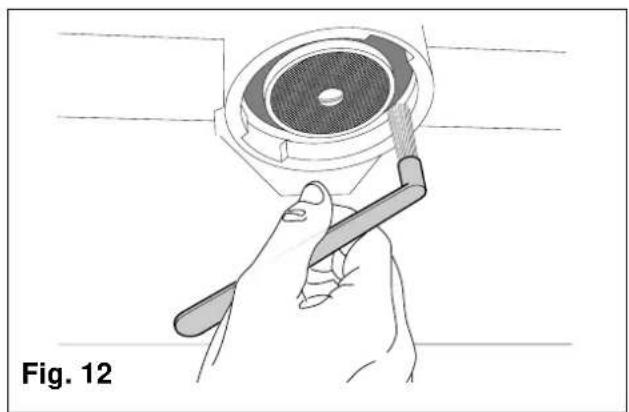
Cleaning the filters and delivery heads (Fig.12)
Operation to be carried out when the machine is off and cold.
● Prepare a solution of 4 sachets of detergent powder Code 69000124 dissolved in a litre of boiling water in a stainless steel, plastic or glass recipient (NOT ALUMINIUM OR IRON).
- Remove the filters and immerse them with the filter holders in the prepared solution, leaving them for at least 10/20 minutes (all night is better).
- Remove them from the container and rinse them thoroughly in running water.
- Remove the cup rack 1 (Fig.12), slide out the drip tray and clean them both.
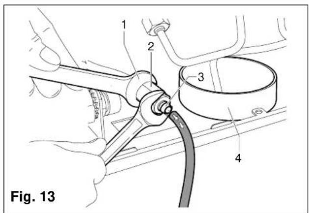
- Check and clean the drainage sump 4 (Fig.13), removing any sludge with the help of a spoon.
10.3. Periodical maintenance

Operation to be carried out while there is still some pressure in the machine.
● Drain the water from the boiler using the hot water tap 7;
● Wait for the machine to te-establish its correct thermal balance before use.

10.3.1. Renewal of water in the boiler (Fig.13)
To be carried out only by qualified personnel.
- Turn off the machine and wait for the pressure in the boiler to diminish (gauge needl on "0").
- Insert a rubber hose into the hose-end fitting (3) (Fig.13)
- Use the wrench (1) to immobilize the fitting (2) and loosen the hose-end fitting (3).
- Allow the water to flow out completely; then, close the fitting (3) and remove the rubber hose.
● Refill the boiler (paragraph 7.3.).
11. STOPPING THE MACHINE
A - Temporary stop
● Carry out cleaning and maintenance operations.
● Wind up the cable and fasten it to the machine with sticky tape.
- Cover the machine and place it in a dry room. Do not leave it exposed to atmospheric agents and do not allow it to be touched by children or unift persons.
To disconnect from the main power supply, consult qualified personnel.
B - Definitive stop
- Besides carrying out the operations necessary for a temporary stop, cut off the cable, pack the machine in cardboard, polystyrene or other packing material and consign it to firms authorized for its disposal or to second-hand goods dealers.
12. PROBLEMS AND REMEDIES

Check operations to be carried out by the user with the plug disconnected.
For any type of problem or inconvenience not specifically indicated, disconnect the plug and contact our service centre without attempting any direct repairs.
A) The machine does not start:
- check that the plug is connected;
- In case of power failure wait for the power to return and check if the earth leakage protection circuit breaker or the main switch is on;
- check the condition of the plug and the supply cable; if damaged have them replaced by qualified personnel.
B) There is water under the machine:
D) Irregular steam delivery:
- check that the nozzles are not obstructed.
13. MACHINES WITH ALTERNATIVE GAS HEATER VERSION (Fig.14)

N.B. Installation of the machine and any adjustment or adaptation to the type of gas should be done by a technically qualified person.

The machine leaves the factory all set for use with liquid gas (GPL).
The gas regulator (1) is therefore fitted with the appropriate injector shown in the table below:
| Model | Nominal thermic capacity | GPL G30 - 29 mbar (cent of millimeter) | Natural gas G20 - 20 mbar (cent of millimeter) |
| 2 Gr. | 2,5 KW (2150 Kcal/h.) | 75 102 | |
| 3-4 Gr | 3,3 KW (2850 Kcal/h.) | 90 135 | |
The primary air intake regulator (2) is set with the reference notch showing “GPL” corresponding to the secuting screw (3).
The flame is regulated (minimum and maximum) to suit this type of gas.
If the machine is to be used with a different type of gas, it will be necessary to replace the injector in accordance with the above table and to rotate the primary air regulator (2), which, in the case of natural gas, will have to be set with the reference notch showing "N" corresponding to the securing screw (3).
To do this, it will of course be necessary to loosen the securing screw (3) and to tighten it again after rotating the primary air intake regulator (2).
Connections to mains gas, from the gas tap available in the room to the valve fitted on the machine, must be carried out in accordance with the regulations in force, using a flexible pipe or a rigid pipe in annealed copper.
In the latter case, the special rubber-pipe fitting in connected tightly to the valve by means of the biconical nozzle and securing nut supplied.
The flexible pipe is fitted over the end of the mains outlet and secured with the metal strip supplied.
Alternatively, the annealed copper pipe can be connected up, again using the special biconical nozzle and the appropriate nuts, directly to the valve.
Once the machine has been connected up to the gas main, and after filling the boiler up with water in accordance with the instructions in the booklet ("INSTRUCTIONS FOR USE AND MAINTENANCE"), the burner can be lit in the following manner:
- Open the main gas tap.
- Press on the gas valve knob, on the machine rotate it 90° anti-clockwise, and keep it pressed in. At the same time, press the piezoelectric lighter one or more times – the lighter knob bears a symbol resembling a spark – until the burner lights up.
- Wair about 20 seconds, then release the valve knob and the burner should stay lit – the flame is visible through the special hole in the panel behind the dispenser units.
N.B.
Should the burner not light up, do not persist, but release the valve knob, and then check that lighter spark on the burner is in order and about 5 mm long.
Should the flame go out when te valve knob is released, check the position of thermocouple and the circuit connected to it.
The flame should be bright blue; if not, slightly regulate the primary air intake (2) until the desired effect is achieved.
Wait until the machine has the correct pressure, according to instructions. Otherwise, adjust the gas pressure regulator, which has two regulating screws.
The one that protrudes more (4) serves to regulate the boiler's operating pressure, while the other (5) serves to set the flame at the minimum.
When the machine is pressurized, check to see that the minimum flame is correct by adjusting the screw (4) if necessary; after loosening the locking-nut, unscrew the screw until it feels loose (the main gas-pipe is closed), and check whether, under these conditions, the low flame remains lit, thus acting as a pilot.
If the flame is too high, it will be necessary to regulate screw (5), turning it slightly clockwise, of course after having loosened the locking-nut. If, on the contrary, the flame tends to go out, then regulate screw (5) by turning it anti-clockwise, until a very low, but constant flame is obtained. Having achieved this correct adjustment of the minimum flame, hold the screw still and lock it with the locking-nut.
Then rotate the screw (4) clockwise until there is a there is a high flame, and wait for the boiler to reach the desired operating pressure: if the flame dies down before reaching the required pressure, tighten screw (4) further; if the flame dies down at a higher pressure, then unscrew the screw.
Check once or twice by opening the steam tap to release the pressure in the boiler, then hold screw (4) still and lock it with the locking-nut.
IT ITALIANO 12-23
FR FRANCAIS 24-35
DE DEUTSCH 36-47
EN ENGLISH 48-59
ES ESPAÑOL 60-71
PT PORTUGUÊS 72-83
SCHEMI ELETTRICI
SCHEMAS ELECTRIQUES
SCHALTPLANE
WIRING DIAGRAMS
1 Interruptor general
1) Connect cable as shown in the picture.
2) On the power board, move resistance connection from connector marked 3VN\~ to connector marked 3V\~
1) Connect cable as shown in the picture.
2) Disconnect the light blue cables (neutral) from electric resistance and insulate them.
3) Connect boiler electric resistance according to the diagram below.
EN Reserved property.
Partial or total reproduction of this manual is forbidden without written authorisation of RANCILIO S.P.A..
RANCILIO reserves the right to effectuate, in any given moment, any modifications which are considered necessary.