
M18 Fuel 287422HD - Bending machine MILWAUKEE - Free user manual and instructions
Find the device manual for free M18 Fuel 287422HD MILWAUKEE in PDF.
| Brand | Milwaukee |
| Model | M18 Fuel 287422HD |
| Product type | Cordless pipe threader |
| Voltage | 18V DC |
| Battery system | M18™ |
| Recommended charger | M18™ |
| No-load speed | 0-29 rpm (speed 1) / 0-41 rpm (speed 2) |
| Threading capacity | 3.2 mm - 50.8 mm (1/8" - 2") |
| Compatible die heads | Series 12-R or R12+ from Ridgid® or equivalent |
| Operating temperature | -18°C to 50°C |
| Connectivity | ONE-KEY™ (mobile app) |
| Rotation direction | Reversible (right/left) |
| Switch | 3 positions (right, left, lock) |
| Side handle | Yes |
| Support arm | Included |
| Clamping jaws | Yes |
| ONE-KEY™ indicator | Blue/red LED |
| Warranty | 5-year limited (USA and Canada) |
| Maintenance | Clean vents, keep handles clean and dry |
| Repairs | Authorized Milwaukee service center |
Frequently Asked Questions - M18 Fuel 287422HD MILWAUKEE
User questions about M18 Fuel 287422HD MILWAUKEE
0 question about this device. Answer the ones you know or ask your own.
Ask a new question about this device
Download the instructions for your Bending machine in PDF format for free! Find your manual M18 Fuel 287422HD - MILWAUKEE and take your electronic device back in hand. On this page are published all the documents necessary for the use of your device. M18 Fuel 287422HD by MILWAUKEE.
USER MANUAL M18 Fuel 287422HD MILWAUKEE
natural_image
Technical line drawing of a Milwaukee fuel injector (no text or symbols on the diagram itself)Cat. No. / No de cat.
2874-20
M18 FUEL™ PIPE THREADER FILETEUR DE TUYAUX M18 FUEL™ PIPE ENHEBRADOR DE TUBERÍAS M18 FUEL™

WARNING To reduce the risk of injury, user must read and understand operator's manual.
⚠ WARNING Read all safety warnings, instructions, illustrations and specifica-
tions provided with this power tool. Failure to follow all instructions listed below may result in electric shock, fire and/or serious injury. Save all warnings and instructions for future reference.
The term "power tool" in the warnings refers to your mains-operated (corded) power tool or battery-operated (cordless) power tool.
WORK AREA SAFETY
- Keep work area clean and well lit. Cluttered or dark areas invite accidents.
- Do not operate power tools in explosive atmospheres, such as in the presence of flammable liquids, gases or dust. Power tools create sparks which may ignite the dust or fumes.
- Keep children and bystanders away while operating a power tool. Distractions can cause you to lose control.
ELECTRICAL SAFETY
- Avoid body contact with earthed or grounded surfaces, such as pipes, radiators, ranges and refrigerators. There is an increased risk of electric shock if your body is earthed or grounded.
- Do not expose power tools to rain or wet conditions. Water entering a power tool will increase the risk of electric shock.
PERSONAL SAFETY
- Stay alert, watch what you are doing and use common sense when operating a power tool. Do not use a power tool while you are tired or under the influence of drugs, alcohol or medication. A moment of inattention while operating power tools may result in serious personal injury.
- Use personal protective equipment. Always wear eye protection. Protective equipment such as a dust mask, non-skid safety shoes, hard hat or hearing protection used for appropriate conditions will reduce personal injuries.
- Prevent unintentional starting. Ensure the switch is in the off-position before connecting to power source and/or battery pack, picking up or carrying the tool. Carrying power tools with your finger on the switch or energizing power tools that have the switch on invites accidents.
- Do not overreach. Keep proper footing and balance at all times. This enables better control of the power tool in unexpected situations.
- Dress properly. Do not wear loose clothing or jewelry. Keep your hair and clothing away from moving parts. Loose clothes, jewelry or long hair can be caught in moving parts.
- Do not let familiarity gained from frequent use of tools allow you to become complacent and ignore tool safety principles. A careless action can cause severe injury within a fraction of a second.
POWER TOOL USE AND CARE
- Do not force the power tool. Use the correct power tool for your application. The correct power tool will do the job better and safer at the rate for which it was designed.
- Do not use the power tool if the switch does not turn it on and off. Any power tool that cannot be controlled with the switch is dangerous and must be repaired.
- Disconnect the plug from the power source and/or remove the battery pack, if detachable, from the power tool before making any adjustments, changing accessories, or storing power tools. Such preventive safety measures reduce the risk of starting the power tool accidentally.
- Store idle power tools out of the reach of children and do not allow persons unfamiliar with the power tool or these instructions to operate the power tool. Power tools are dangerous in the hands of untrained users.
- Maintain power tools and accessories. Check for misalignment or binding of moving parts, breakage of parts and any other condition that may affect the power tool's operation. If damaged, have the power tool repaired before use. Many accidents are caused by poorly maintained power tools.
- Keep cutting tools sharp and clean. Properly maintained cutting tools with sharp cutting edges are less likely to bind and are easier to control.
- Use the power tool, accessories and tool bits etc. in accordance with these instructions, taking into account the working conditions and the work to be performed. Use of the power tool for operations different from those intended could result in a hazardous situation.
- Keep handles and grasping surfaces dry, clean and free from oil and grease. Slippery handles and grasping surfaces do not allow for safe handling and control of the tool in unexpected situations.
BATTERY TOOL USE AND CARE
- Recharge only with the charger specified by the manufacturer. A charger that is suitable for one type of battery pack may create a risk of fire when used with another battery pack.
- Use power tools only with specifically designated battery packs. Use of any other battery packs may create a risk of injury and fire.
- When battery pack is not in use, keep it away from other metal objects, like paper clips, coins, keys, nails, screws or other small metal objects, that can make a connection from one terminal to another. Shorting the battery terminals together may cause burns or a fire.
- Under abusive conditions, liquid may be ejected from the battery; avoid contact. If contact accidentally occurs, flush with water. If liquid contacts eyes, additionally seek medical help. Liquid ejected from the battery may cause irritation or burns.
- Do not use a battery pack or tool that is damaged or modified. Damaged or modified batteries may exhibit unpredictable behavior resulting in fire, explosion or risk of injury.
- Do not expose a battery pack or tool to fire or excessive temperature. Exposure to fire or temperature above 265^ (130°C) may cause explosion.
- Follow all charging instructions and do not charge the battery pack or tool outside the temperature range specified in the instructions. Charging improperly or at temperatures outside the specified range may damage the battery and increase the risk of fire.
SERVICE
- Have your power tool serviced by a qualified repair person using only identical replacement parts. This will ensure that the safety of the power tool is maintained.
- Never service damaged battery packs. Service of battery packs should only be performed by the manufacturer or authorized service providers.
SPECIFIC SAFETY RULES FOR PIPE THREADER
• Always use the support device provided with the tool. Loss of control during operation can result in personal injury.
- Keep sleeves and jackets buttoned while operating the tool. Do not reach across the tool or pipe. Clothing can be caught by the pipe or the tool resulting in entanglement.
- Only one person must control the work process and tool operation. Additional people involved in the process may result in unintended operation and personal injury.
- Keep floors dry and free of slippery materials such as oil. Slippery floors invite accidents.
- When threading or backing die head off pipe, firmly hold the tool to resist forces regardless of support device used. This will reduce the risk of striking, crushing and other injuries.
- Do not use dies that are showing signs of wear, dull, or damaged. Sharp cutting tools require less torque and the tool is easier to control.
- Only use Ridgid® 12-R or R12+ series or equivalent die heads. Other die heads may not fit correctly in the tool increasing the risk of equipment damage and personal injury.
- Do not store die heads in tool to prevent metal on metal wear.
• Always use common sense and be cautious when using tools. It is not possible to anticipate every situation that could result in a dangerous outcome. Do not use this tool if you do not understand these operating instructions or you feel the work is beyond your capability; contact Milwaukee Tool or a trained professional for additional information or training.
- Maintain labels and nameplates. These carry important information. If unreadable or missing, contact a MILWAUKEE service facility for a free replacement.
WARNING
Some dust created by power sanding, sawing, grinding, drilling, and other construction activities contains chemicals known to cause cancer, birth defects or other reproductive harm. Some examples of these chemicals are:
- lead from lead-based paint
- crystalline silica from bricks and cement and other masonry products, and
• arsenic and chromium from chemically-treated lumber. Your risk from these exposures varies, depending on how often you do this type of work. To reduce your exposure to these chemicals: work in a well ventilated area, and work with approved safety equipment, such as those dust masks that are specially designed to filter out microscopic particles.
SPECIFICATIONS
Cat. No....2874-20
Volts.... 18 DC
Battery Type ......M18™
Charger Type......M18™
Recommended Ambient
Operating Temperature 0°F to 125°F
Capacity 1/8" - 2" (3.2 mm - 50.8 mm)
Die Head... Ridgid® 12-R/R12+ series or equivalent
No Load RPM 0 - 29 / 0 - 41
SYMBOLOGY


Direct Current

alert symbol

Read operator's manual

wear gloves while pushing near moving parts

Always use support arm

Keep hands away from moving parts

UL Listing for Canada and U.S.
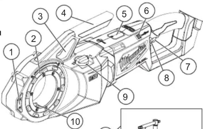
FUNCTIONAL DESCRIPTION
text_image
Technical diagram of a mechanical device with numbered components for identification- Side grip
- Die head lock ring
- Support arm bracing point
- Carry handle
- Internal battery
-
ONE-KEY ^TM indicator
-
Trigger
-
Control switch
-
Speed selector
-
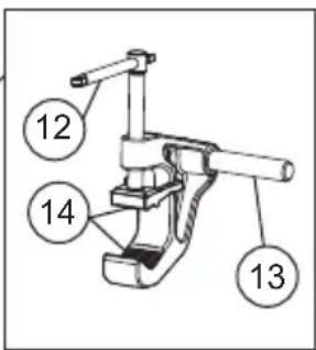
Torque keys
-
Support clamp
-
Tightening arm
-
Support arm
-
Jaws
text_image
12 14 13ASSEMBLY
WARNING
Recharge only with the charger specified for the battery. For spe-ng instructions, read the operator's lied with your charger and battery.
Removing/Inserting the Battery
To remove the battery, push in the release buttons and pull the battery pack away from the tool.
WARNING
Always remove battery pack before changing or removing accessories.
To insert the battery, slide the pack into the body of the tool. Make sure it latches securely into place.
WARNING
Only use accessories specifically recommended for this tool. Others dous.
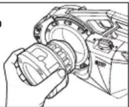
Installing/Removing Die Heads
Die head can be inserted from either side of the tool.
- Remove battery pack.
- Rotate the die head lock ring to the unlocked position.
-
Insert the die head and rotate back and forth slightly to engage torque keys.
-
Rotate the die head lock ring to lock. The lock ring will click when locked.
-
Always check the die head is locked into the tool before starting a cut.
-
To remove, unlock the die head lock ring and pull the die head from the tool.
natural_image
Line drawing of a hand operating a mechanical component with no visible text or symbolsONE-KEY™
To learn more about the ONE-KEY™ functionality for this tool, please reference the Quick Start guide included with this product or go to milwaukeeetool.com/One-Key. To download the ONE-KEY™ app, visit the App Store or Google Play from your smart device.
| ONE-KEYTM Indicator | |
| Solid Blue Wi | reless mode is active and ready to be configured via the ONE-KEYTM app. |
| Blinking Blue | Tool is actively communicating with the ONE-KEYTM app. |
| Blinking Red | Tool is in security lockout and can be unlocked by the owner via the ONE-KEYTM app. |
OPERATION
WARNING
To reduce the risk of injury, always wear proper eye protection marked h ANSI Z87.1.
Resisting Threading Forces
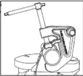
Always use the support device provided with the tool. The support arm clamps to the pipe and helps to resist the threading forces. WARNING! Loss of control during operation can result in personal injury.
- Position the support arm jaws around the pipe. To properly place the support arm for threading, the support arm should be parallel to the pipe and the end of the support arm should match up with the end of the pipe.
- Turn the tightening arm to clamp down securely on the pipe.
- Place the tool with installed die head over the pipe.
- Slide the support arm through the tool's support arm bracing point. WARNING! Do not attach the tool to the support arm in any other location.
- Continue to slide the tool over the pipe until the end of the pipe contacts the cutting dies in the die head. The support arm will be inside the tool's bracing point.
natural_image
Technical line drawing of a mechanical clamp or lever assembly (no text or symbols)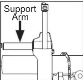
text_image
Support Arm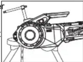
natural_image
Technical line drawing of a mechanical device with no visible text or symbolsSelecting Speed
The speed selector is on top of the housing. Allow the tool to come to a complete stop before changing speeds.
- For pipe diameter 1-1/4" or larger, turn the dial to "1".
- For pipe diameter less than 1-1/4" diameter, turn the dial to "2".
natural_image
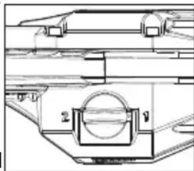
Technical line drawing of a mechanical assembly with labeled components (no readable text or symbols)Using the Control Switch
text_image
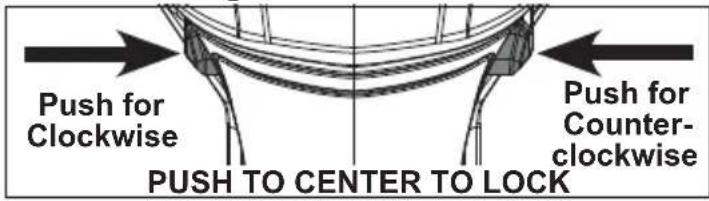
Push for Clockwise Push to CENTER TO LOCK Push for Counter- clockwiseThe control switch may be set to three positions: Clockwise, counterclockwise, and lock. Always allow the motor to come to a complete stop before using the control switch.
For clockwise ▲ rotation, push in the control switch from the left side of the tool. Check the direction of rotation before use. This rotation will produce right-hand threads when the die is inserted from the left (front) side of the tool.
For counterclockwise ▼ rotation, push in the control switch from the right side of the tool. Check direction of rotation before use. This rotation will produce right-hand threads when the die is inserted from the right (back) side of the tool.
To lock the trigger, push the control switch to the center position. The trigger will not work while the control switch is in the center locked position. Always lock the trigger or remove the battery pack before performing maintenance, changing accessories, storing the tool and any time the tool is not in use.
Threading
Properly prepare the pipe. Make sure the pipe is squarely cut and deburred. Pipe cut at an angle can damage the dies while threading and can cause difficulty engaging the die head. The pipe must be stable and secured to prevent tipping during use. Use appropriate pipe stands to support pipe length.
To cut Right-Handed Threads:
-
Position the die head over the pipe end and support the tool as directed in "Resisting Threading Forces".
-
Position the control switch to "clockwise" ▲ for dies inserted from the left side of the tool. Position the control switch to "counterclockwise" ▼ for dies inserted from the right side of the tool.
-
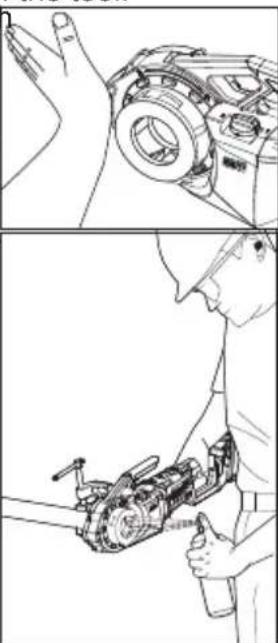
To start the thread, push against the side grip with the palm of the free hand, and slowly pull the trigger. WARNING! Do not wear jewelry, loose fitting clothing, or use a rag while operating tool. Do not wear gloves prone to snagging while pushing on or near moving parts; this increases the risk of entanglement and injury. Once the dies engage the pipe, threads will be cut as the dies pull themselves onto the end of the pipe.
WARNING! Always firmly hold the tool to resist the tool forces. Support devices could, in rare cases, slip and allow the tool to move.
natural_image
Technical line drawing showing hands operating a mechanical device and a close-up of a tool interacting with a mechanical component (no text or symbols present)- Once the dies have engaged the pipe, stop pushing on the side grip and use an oiler to apply a generous quantity of thread-cutting oil to the area. This will lower the necessary threading torque, improve thread quality, and increase die life.
- Release the trigger when the end of the pipe is even with the end of the dies.
natural_image
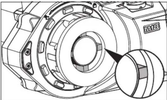
Technical line drawing of a mechanical component with a magnified inset showing a circular feature (no text or symbols)- Use the control switch to reverse the tool. Pull the trigger to thread the die head off of the pipe. WARNING! Always firmly hold the tool to resist the tool forces. Support devices could, in rare cases, slip and allow the tool to move.
- Release the trigger and remove the tool from the pipe.
- Maintain the tool and die head after use. Remove battery pack and clean oil and cutting debris from the tool and die. WARNING! Cuttings may be sharp. Clean up any oil spills to maintain a safe work environment.
For Left-Handed Threads, reverse the clockwise/ counterclockwise selections.
Inspecting Threads/Using a Ring Gauge
- Wipe any oil, chips or debris from the thread.
- Inspect the thread. Threads should be smooth, complete, and in good form. If irregularities such as thread tearing, thin threads, or pipe out-of-roundness are seen, the thread may not seal.
- To check the size of the thread with a ring gauge, thread the gauge onto the pipe and hand-tighten. The end of the pipe should be flush with the side of the gauge (plus or minus one turn). If thread does not gauge properly, cut off the thread, adjust the die head, and cut another thread. WARNING! Using a thread that does not gauge properly can cause leaks.
MAINTENANCE
⚠ WARNING To reduce the risk of injury, always unplug the charger and remove the battery pack from the charger or tool before performing any maintenance. Never disassemble the tool, battery pack or charger. Contact a MILWAUKEE service facility for ALL repairs.
Maintaining Tool
Keep your tool, battery pack and charger in good repair by adopting a regular maintenance program. Inspect your tool for issues such as undue noise, misalignment or binding of moving parts, breakage of parts, or any other condition that may affect the tool operation. Return the tool, battery pack, and charger to a MILWAUKEE service facility for repair. After six months to one year, depending on use, return the tool, battery pack and charger to a MILWAUKEE service facility for inspection.
If the tool does not start or operate at full power with a fully charged battery pack, clean the contacts on the battery pack. If the tool still does not work properly, return the tool, charger and battery pack, to a MILWAUKEE service facility for repairs.
Cleaning
After each use, clean tool of any oil, grease, chips, dirt, or residue. Keep tool clean, dry and free of oil or grease. Use only mild soap and a damp cloth to clean, since certain cleaning agents and solvents are harmful to plastics and other insulated parts. Some of these include gasoline, turpentine, lacquer thinner, paint thinner, chlorinated cleaning solvents, ammonia and household detergents containing ammonia. Never use flammable or combustible solvents around tools.
ONE-KEY™
WARNING
Chemical Burn Hazard. This device contains a
lithium button/coin cell battery. A new or used battery can cause severe internal burns and lead to death in as little as 2 hours if swallowed or enters the body. Always secure the battery cover. If it does not close securely, stop using the device, remove the batteries, and keep it away from children. If you think batteries may have been swallowed or entered the body, seek immediate medical attention.

Internal Battery
An internal battery is used to facilitate full ONE-KEY ^™ functionality.
To replace the battery:
- Remove the battery pack.
- Remove the screw(s) and open the battery door.
- Remove the old battery, keep it away from children, and dispose of it properly.
- Insert the new battery (3V CR2032), with the positive side facing up.
- Close the battery door and tighten the screw securely.
WARNING
To reduce the risk of personal injury and damage, never immersettery pack or charger in liquid or to flow inside them.
Repairs
For repairs, return the tool, battery pack and charger to the nearest service center.
ACCESSORIES
WARNING
Use only recommended accessories. Others may be hazardous.
For a complete listing of accessories, go online to www.milwaukeetool.com or contact a distributor.
SERVICE - UNITED STATES
1-800-SAWDUST (1.800.729.3878)
Monday-Friday, 7:00 AM - 6:30 PM CST
or visit www.milwaukeetool.com
Contact Corporate After Sales Service Technical Support with technical, service/repair, or warranty questions.
Email: metproductsupport@milwaukeeetool.com
Become a Heavy Duty Club Member at www.milwaukeeetool.com to receive important notifications regarding your tool purchases.
SERVICE - CANADA
Milwaukee Tool (Canada) Ltd 1.800.268.4015
Monday-Friday, 7:00 AM - 4:30 PM CST
or visit www.milwaukeetool.ca
LIMITED WARRANTY USA & CANADA
Every MILWAUKEE power tool* (see exceptions below) is warranted to the original purchaser only to be free from defects in material and workmanship. Subject to certain exceptions, MILWAUKEE will repair or replace any part on an electric power tool which, after examination, is determined by MILWAUKEE to be defective in material or workmanship for a period of five (5) years** after the date of purchase unless otherwise noted. Return of the power tool to a MILWAUKEE factory Service Center location or MILWAUKEE Authorized Service Station, freight prepaid and insured, is required. A copy of the proof of purchase should be included with the return product. This warranty does not apply to damage that MILWAUKEE determines to be from repairs made or attempted by anyone other than MILWAUKEE authorized personnel, misuse, alterations, abuse, normal wear and tear, lack of maintenance, or accidents.
Normal Wear: Many power tools need periodic parts replacement and service to achieve best performance. This warranty does not cover repair when normal use has exhausted the life of a part including, but not limited to, chucks, brushes, cords, saw shoes, blade clamps, o-rings, seals, bumpers, driver blades, pistons, strikers, lifters, and bumper cover washers.
*This warranty does not cover Air Nailers & Staplers; Airless Paint Sprayer; Cordless Battery Packs; Gasoline Driven Portable Power Generators; Hand Tools; Hoist – Electric, Lever & Hand Chain; M12™ Heated Gear; Reconditioned Product; and Test & Measurement Products. There are separate and distinct warranties available for these products.
**The warranty period for Job Site Radios, M12™ Power Port, M18™ Power Source, Jobsite Fan and Trade Titan™ Industrial Work Carts is one (1) year from the date of purchase. The warranty period for the Drain Cleaning Cables and AIRSNAKE™ Drain Cleaning Air Gun Accessories is two (2) years from the date of purchase. The warranty period for the M18™ Compact Heat Gun, 8 Gallon Dust Extractor, M18™ Framing Nailers, M18 FUEL™ 1/2" Ext. Anvil Controlled Torque Impact Wrench w/ ONE-KEY™, and the M18 FUEL™ 1" High Torque Impact Wrench w/ ONE-KEY™ is three (3) years from the date of purchase. The warranty period for the LED in the LED Work Light and the LED Upgrade Bulb for the Work Light is the lifetime of the product subject to the limitations above. If during normal use the LED or LED Bulb fails, the part will be replaced free of charge.
Warranty Registration is not necessary to obtain the applicable warranty on a MILWAUKEE power tool product. The manufacturing date of the product will be used to determine the warranty period if no proof of purchase is provided at the time warranty service is requested. ACCEPTANCE OF THE EXCLUSIVE REPAIR AND REPLACEMENT REMEDIES DESCRIBED HEREIN IS A CONDITION OF THE CONTRACT FOR THE PURCHASE OF EVERY MILWAUKEE PRODUCT. IF YOU DO NOT AGREE TO THIS CONDITION, YOU SHOULD NOT PURCHASE THE PRODUCT. IN NO EVENT SHALL MILWAUKEE BE LIABLE FOR ANY INCIDENTAL, SPECIAL, CONSEQUENTIAL OR PUNITIVE DAMAGES, OR FOR ANY COSTS, ATTORNEY FEES, EXPENSES, LOSSES OR DELAYS ALLEGED TO BE AS A CONSEQUENCE OF ANY DAMAGE TO, FAILURE OF, OR DEFECT IN ANY PRODUCT INCLUDING, BUT NOT LIMITED TO, ANY CLAIMS FOR LOSS OF PROFITS. SOME STATES DO NOT ALLOW THE EXCLUSION OR LIMITATION OF INCIDENTAL OR CONSEQUENTIAL DAMAGES, SO THE ABOVE LIMITATION OR EXCLUSION MAY NOT APPLY TO YOU. THIS WARRANTY IS EXCLUSIVE AND IN LIEU OF ALL OTHER EXPRESS WARRANTIES, WRITTEN OR ORAL. TO THE EXTENT PERMITTED BY LAW, MILWAUKEE DISCLAIMS ANY IMPLIED WARRANTIES, INCLUDING WITHOUT LIMITATION ANY IMPLIED WARRANTY OF MERCHANTABILITY OR FITNESS FOR A PARTICULAR USE OR PURPOSE; TO THE EXTENT SUCH
DISCLAIMER IS NOT PERMITTED BY LAW, SUCH IMPLIED WARRANTIES ARE LIMITED TO THE DURATION OF THE APPLICABLE EXPRESS WARRANTY AS DESCRIBED ABOVE. SOME STATES DO NOT ALLOW LIMITATIONS ON HOW LONG AN IMPLIED WARRANTY LASTS, SO THE ABOVE LIMITATION MAY NOT APPLY TO YOU, THIS WARRANTY GIVES YOU SPECIFIC LEGAL RIGHTS, AND YOU MAY ALSO HAVE OTHER RIGHTS WHICH VARY FROM STATE TO STATE.
This warranty applies to product sold in the U.S.A. and Canada only. Please consult the 'Service Center Search' in the Parts & Service section of MILWAUKEE's website www.milwaukeeetool.com or call 1.800.SAWDUST (1.800.729.3878) to locate your nearest service facility for warranty and non-warranty service on a Milwaukee electric power tool.
LIMITED WARRANTY - MEXICO, CENTRAL AMERICA & CARIBBEÁN
TECHTRONIC INDUSTRIES' warranty is for 5 years since the original purchase date.
This warranty card covers any defect in material and workmanship on this Product.
To make this warranty valid, present this warranty card, sealed/stamped by the distributor or store where you purchased the product, to the Authorized Service Center (ASC). Or, if this card has not been sealed/stamped, present the original proof of purchase to the ASC. Call 55 4160-3547 to find the nearest ASC, for service, parts, accessories or components.
Procedure to make this warranty valid
Take the product to the ASC, along with the warranty card sealed/ stamped by the distributor or store where you purchased the product, and any faulty piece or component will be replaced without cost for you. We will cover all freight costs relative with this warranty process. Exceptions
This warranty is not valid in the following situations
a) When the product is used in a different manner from the end-user guide or instruction manual.
b) When the conditions of use are not normal.
c) When the product was modified or repaired by people not authorized by TECHTRONIC INDUSTRIES.
Note: If cord set is damaged, it should be replaced by an Authorized Service Center to avoid electric risks.
SERVICE AND ATTENTION CENTER
Call to 55 4160-3547
IMPORTED AND COMMERCIALIZED BY
TECHTRONIC INDUSTRIES MEXICO, S.A. DE C.V.
Miguel de Cervantes Saavedra No.301 Piso 5, Torre Norte
text_image
Technical diagram of a Ultrasonic camera with numbered components for identificationnatural_image
Line drawing of a hand holding a mechanical component (no text or symbols visible)natural_image
Technical line drawing of a mechanical clamp or clamping device (no text or symbols)text_image
Bras de support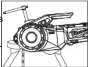
natural_image
Technical line drawing of a mechanical device with no visible text or symbolsnatural_image
Technical line drawing of a mechanical assembly with no visible text or symbolsnatural_image
Line drawing of a hand holding a camera lens (no text or symbols)natural_image
Line drawing of a person using a mechanical device to interact with another person (no text or symbols present)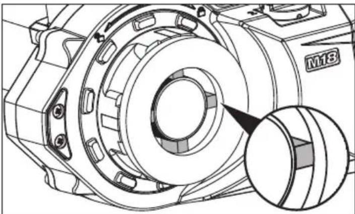
natural_image
Technical line drawing of a mechanical assembly with a magnified inset showing a circular component (no text or symbols)Milwaukee Tool (Canada) Ltd 1.800.268.4015
Monday-Friday, 7:00 AM - 4:30 PM CST
www.milwaukeetool.ca
GARANTIE LIMITÉE- AUX ÉTATS-UNIS ET AU CANADA
text_image
Technical diagram of a video camera with numbered components for identificationnatural_image
Technical line drawing of a mechanical assembly with a hand operating a motor (no text or symbols visible)ONE-KEY™
natural_image
Technical line drawing of a mechanical clamp or clamping device (no text or symbols)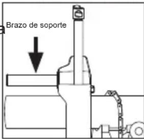
natural_image
Technical line drawing of a mechanical device with no visible text or symbolsnatural_image
Technical line drawing of a mechanical assembly with no visible text or symbolsnatural_image
Line drawing of a camera with a hand pointing to the left side (no text or symbols)natural_image
Line drawing of a person assembling or adjusting a mechanical component (no text or symbols visible)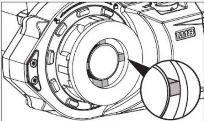
natural_image
Technical line drawing of a mechanical assembly with a magnified inset showing a circular component (no text or symbols)Lunes a Viernes (9am a 6pm)
13135 West Lisbon Road
Brookfield, WI 53005 USA
58140139d2 961013192-02(A)
08/19 Printed in China