
Haiku I 32 WH - Iron ELICA - Free user manual and instructions
Find the device manual for free Haiku I 32 WH ELICA in PDF.

| Product Type | Range hood |
| Brand | Elica |
| Model | Haiku I 32 WH |
| Usage Version | Extraction (external exhaust) or recirculation (internal recycling) |
| Number of Speeds | 3 speeds + 2 Boost speeds (Boost 1: 30 min, Boost 2: 7 min) |
| Lighting | LED, replacement by technical service |
| Grease Filter | Metal, dishwasher-safe, monthly cleaning |
| Charcoal Filter (recirculation version) | Washable with hot water or dishwasher, oven dry 10 min at 100°C, replace every 3 years |
| Filter Saturation Indicator | Yes, slow flashing for grease filter, fast for odor filter |
| Minimum Safety Distance | 60 cm for electric cooktop, 65 cm for gas or mixed |
| Exhaust Duct Diameter | Equal to the diameter of the connection flange (not supplied) |
| Power Supply | According to rating plate (inside) |
| Electrical Protection | Standard circuit breaker for total disconnection if no accessible plug |
| Materials | Not specified, but likely steel and glass |
| Safety Standards | EN/IEC 60335-1, EN/IEC 60335-2-31, EN/IEC 62233 |
| Performance Standards | EN/IEC 61591, ISO 5167, EN/IEC 60704, etc. |
| EMC Standards | EN 55014-1, CISPR 14-1, EN/IEC 61000 |
| Recycling Class | Compliant with WEEE 2012/19/EC |
| Number of Pages in Manual | 124 |
| Weight | Not specified, heavy appliance requiring two people for installation |
Frequently Asked Questions - Haiku I 32 WH ELICA
User questions about Haiku I 32 WH ELICA
0 question about this device. Answer the ones you know or ask your own.
Ask a new question about this device
Download the instructions for your Iron in PDF format for free! Find your manual Haiku I 32 WH - ELICA and take your electronic device back in hand. On this page are published all the documents necessary for the use of your device. Haiku I 32 WH by ELICA.
USER MANUAL Haiku I 32 WH ELICA
EN Instruction on mounting and use
natural_image
Technical line drawings of two mechanical or electrical components with no visible text or symbols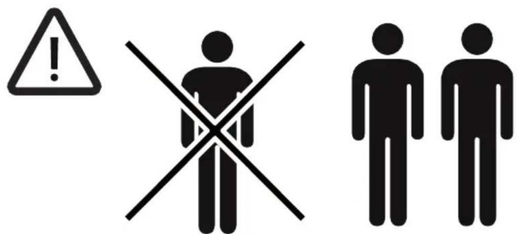
natural_image
Pure mechanical diagram showing a piston-cylinder assembly with no text or symbols1
natural_image
Pure mechanical diagram showing a piston-cylinder assembly with directional arrows indicating force or motion (no text or symbols)2
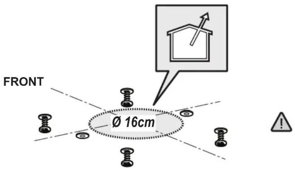
5
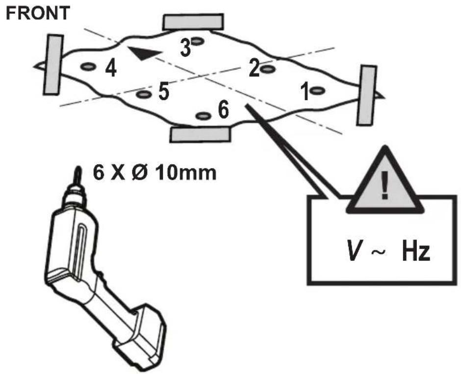
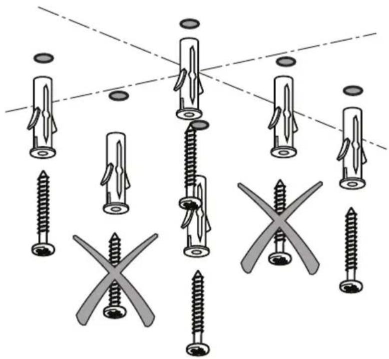
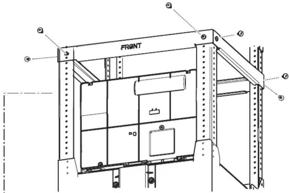
FRONT
4 x ∅4 x 70mm

6 x ∅ 10mm
6
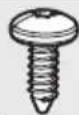
natural_image
Diagram showing various screw types and cross-shaped features, no text or symbols present
7
8
natural_image
Icon depicting a pencil writing on a document with a calculator (no text or symbols)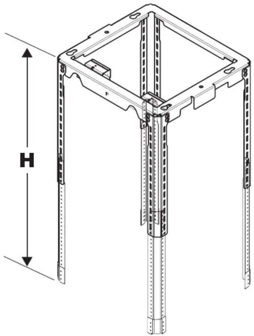
natural_image
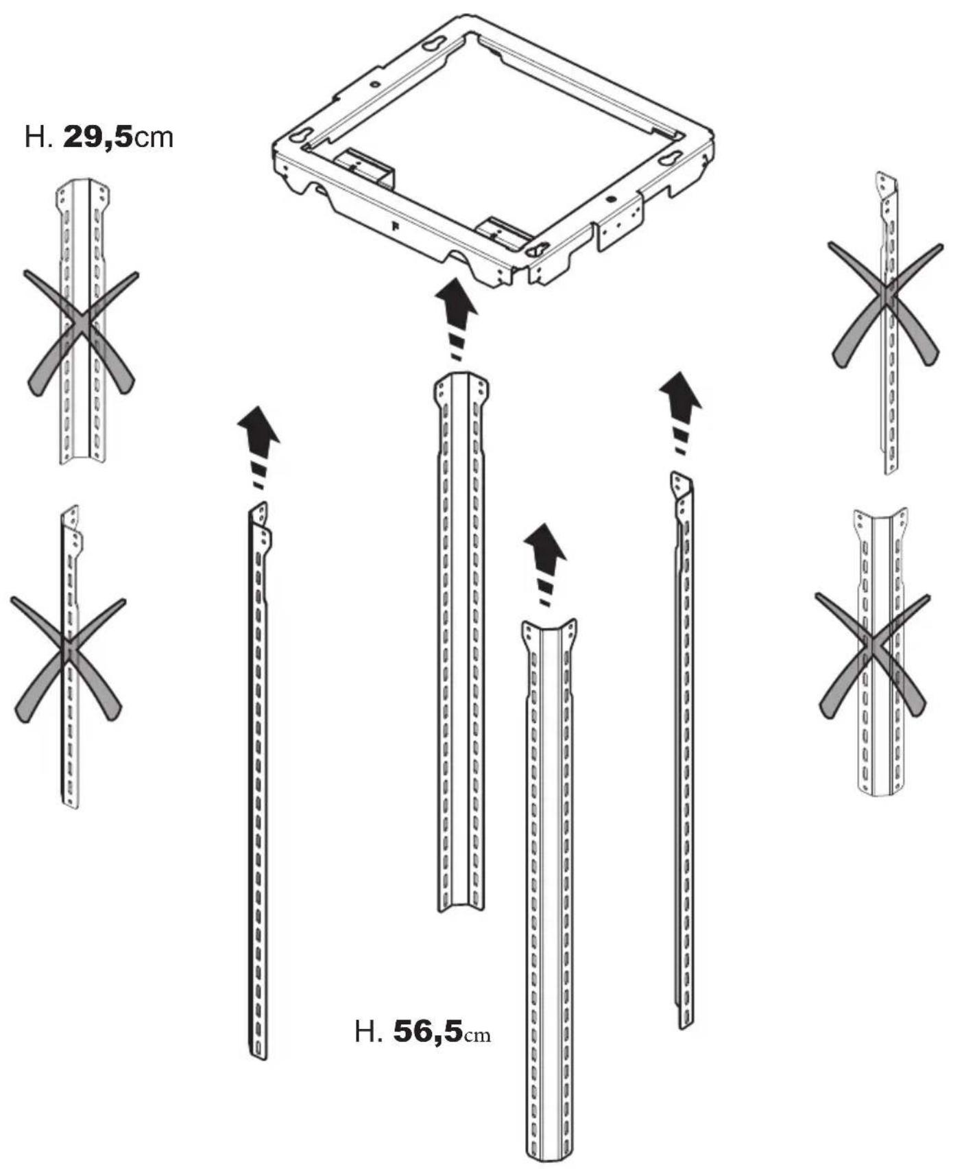
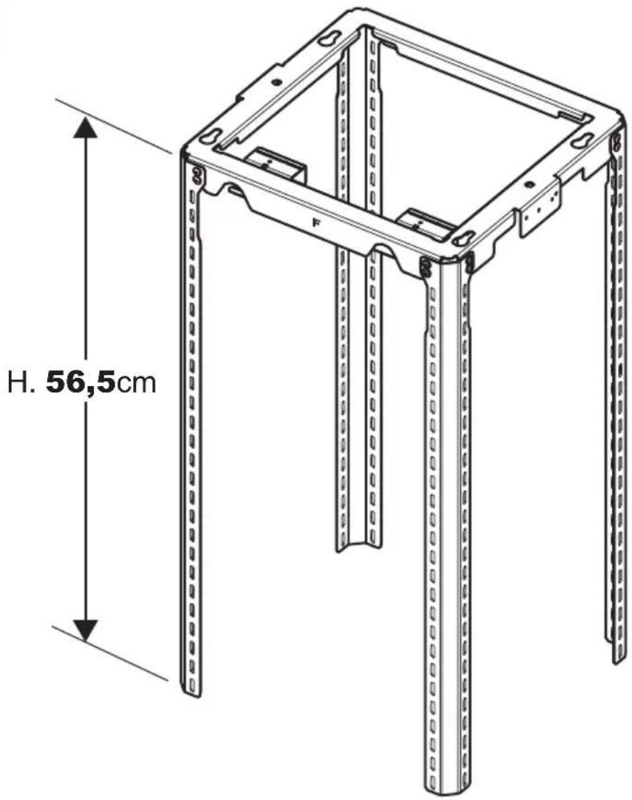
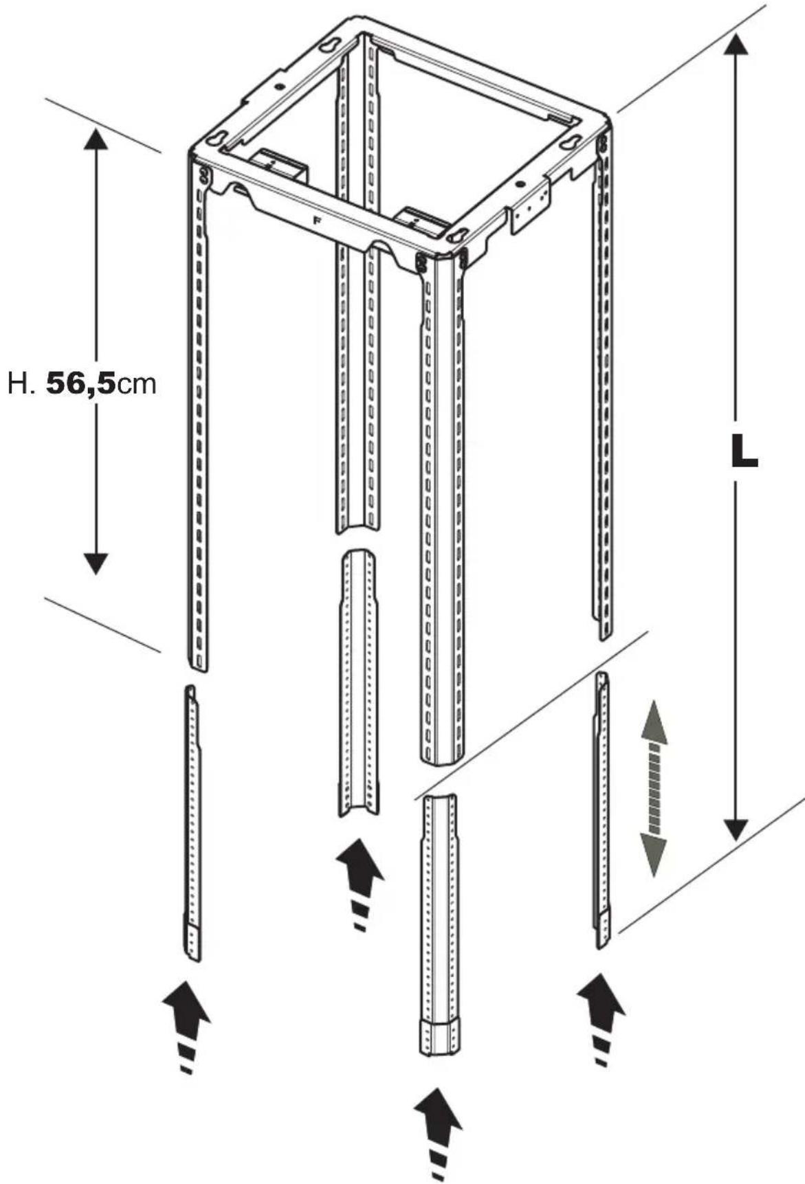
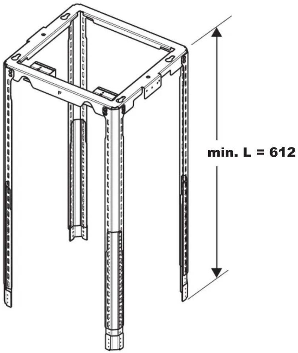
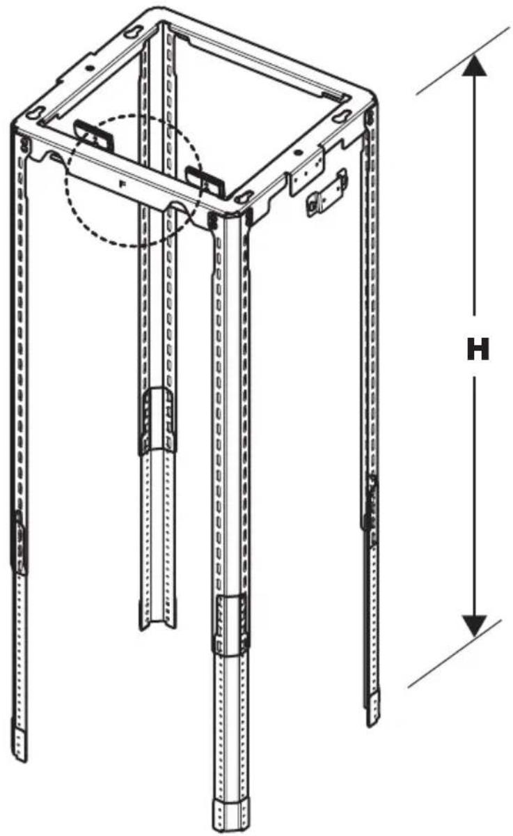
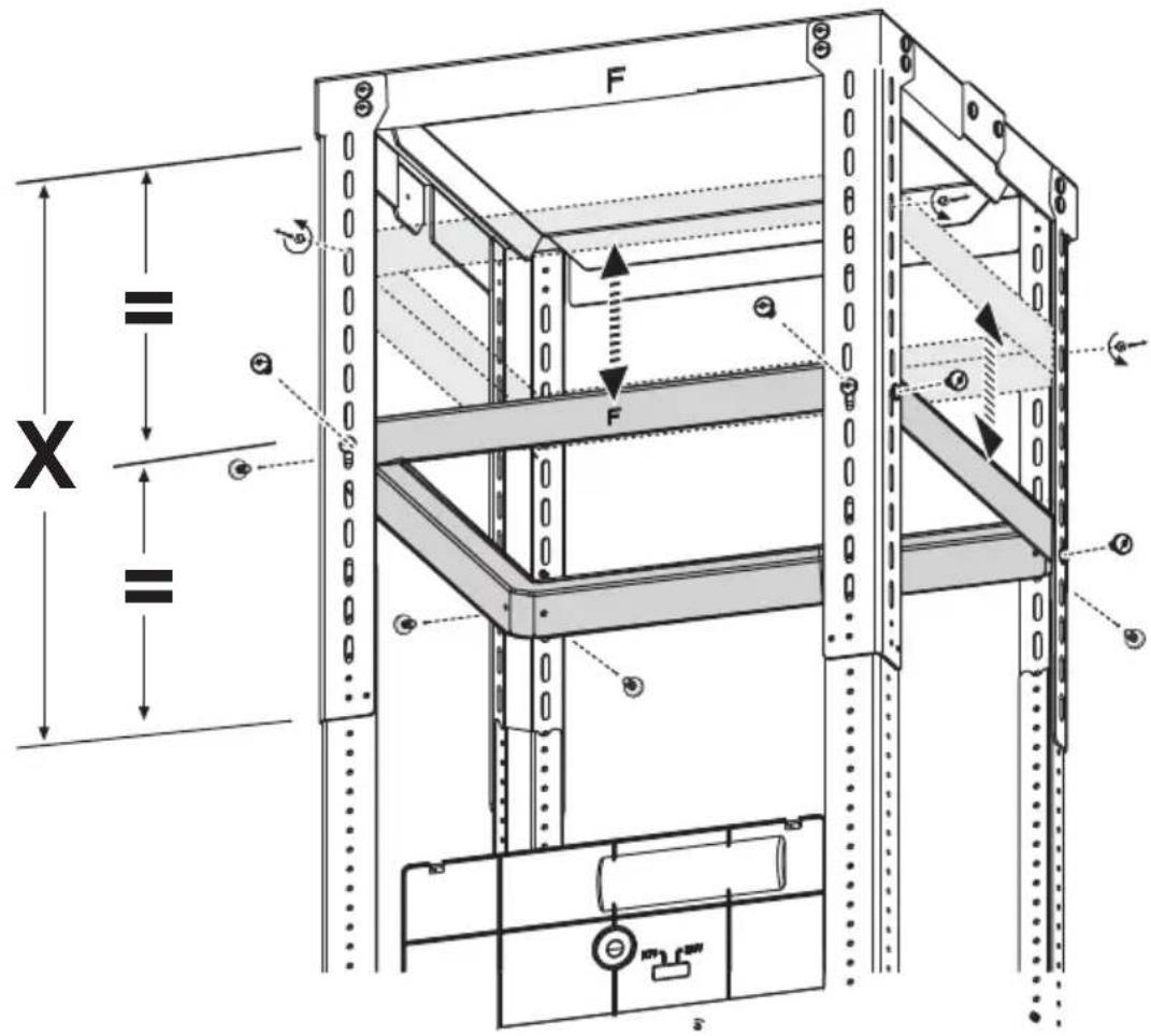
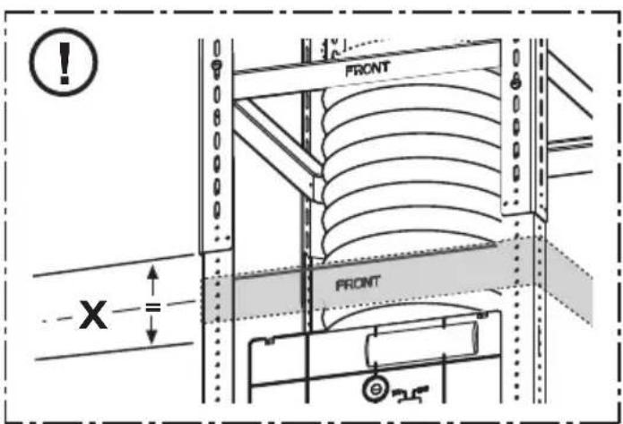
Technical line drawing of a mechanical frame structure with vertical supports and a dimension label H (no text or symbols beyond measurement indicators)
$$ \mathbf {H} _ {\mathrm{(cm)}} = (\mathbf {X} - \mathbf {Y} - 4 8, 5 \mathrm{cm}) $$

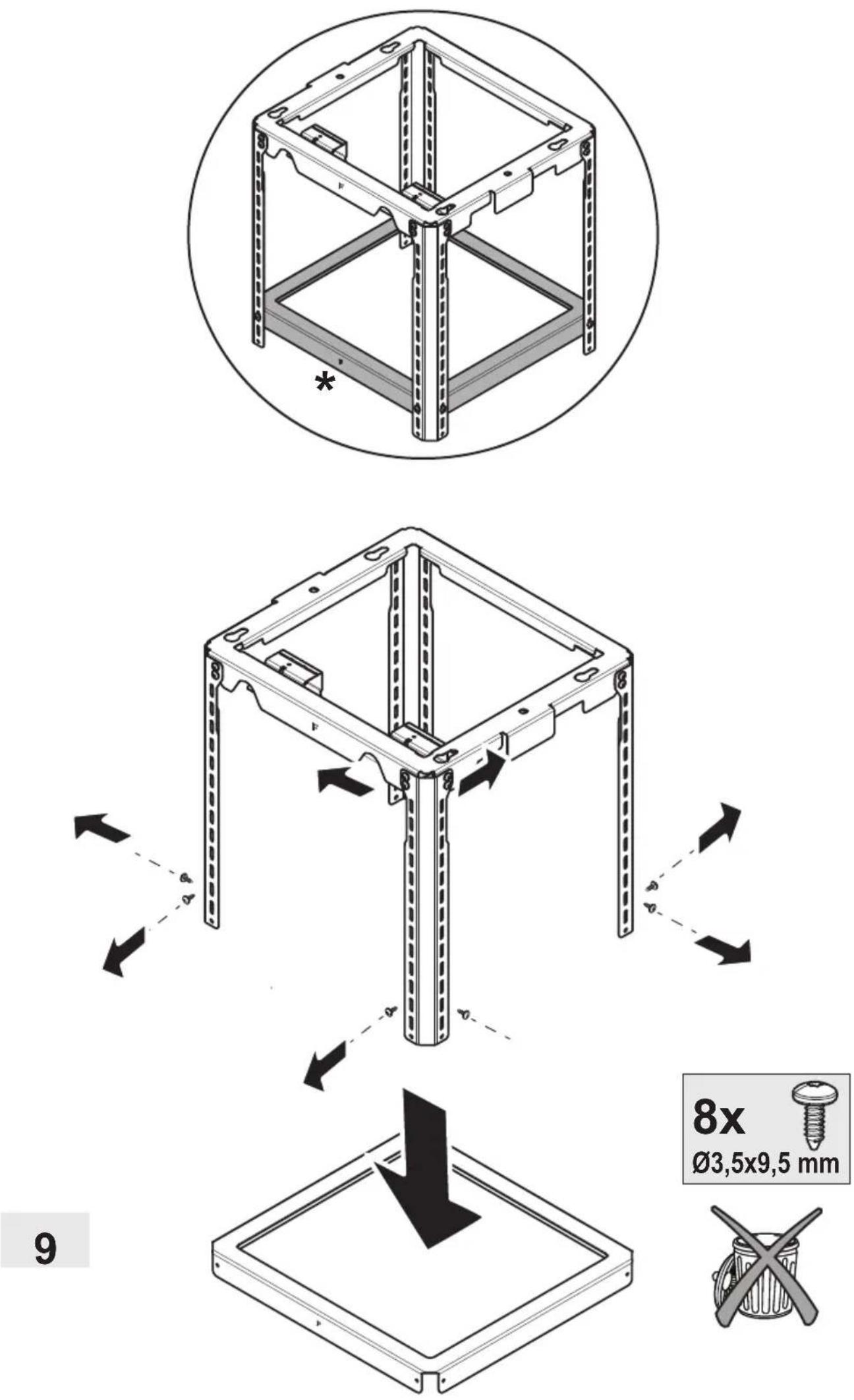
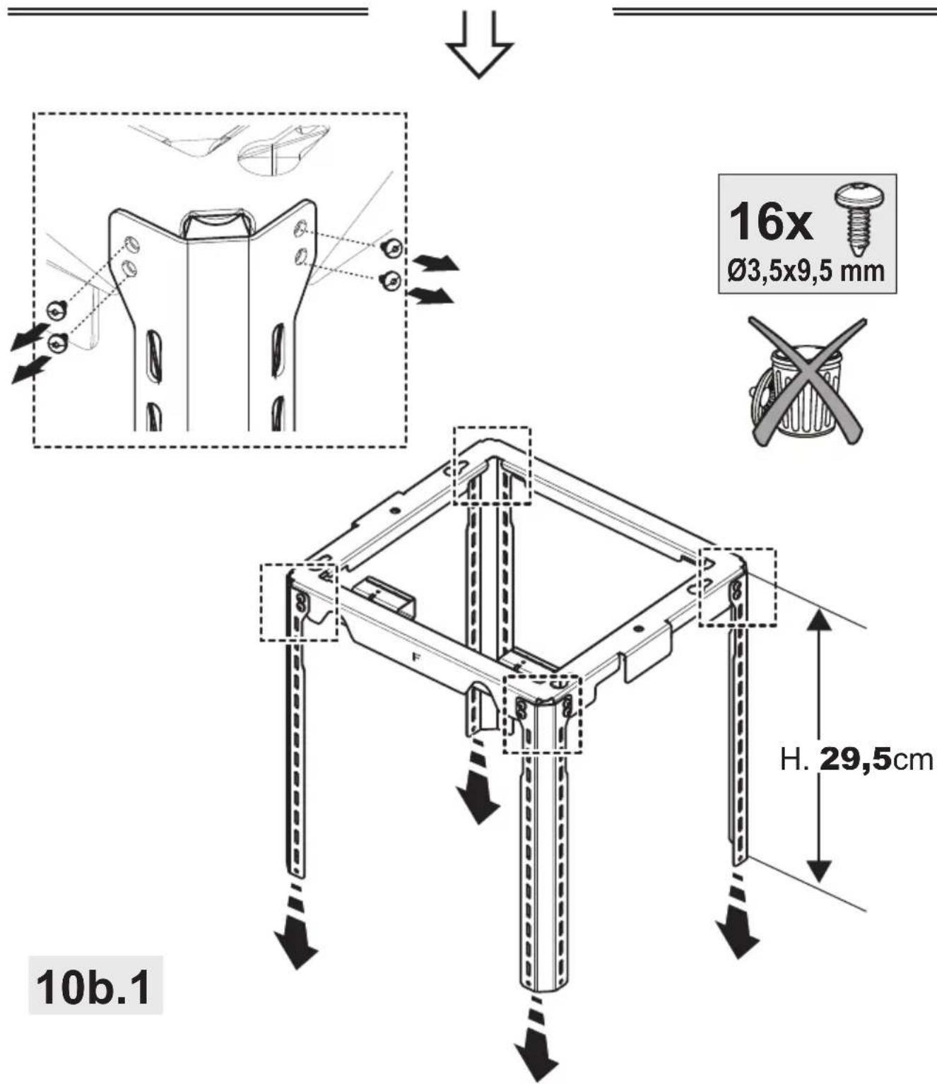
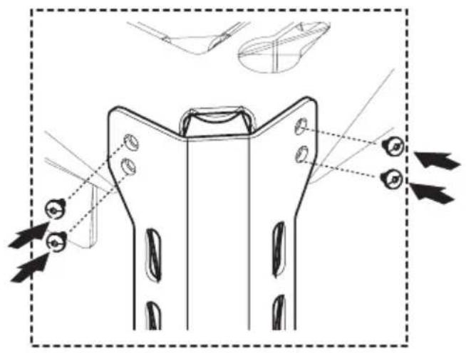
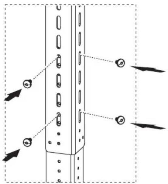
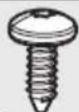
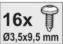
16x
∅3,5x9,5 mm
natural_image
Technical line drawing of a mechanical frame structure with mounting holes and structural supports (no text or symbols)
10a.2

natural_image
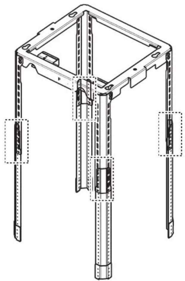
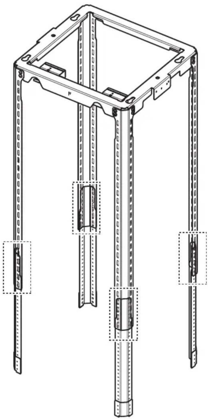
Simple line drawing of a structural support frame with diagonal beams and vertical supports (no text or symbols)L= 110-117 (cm)
L= 110-125 (cm)


natural_image
Technical line drawing of a mechanical component with mounting holes and directional arrows indicating assembly (no text or symbols)16x
∅3,5x9,5 mm
10b.3
10b.4
natural_image
Technical diagram of a vertical mechanical component with mounting holes and directional arrows indicating assembly (no text or symbols)16x
∅3,5x9,5 mm
natural_image
Technical line drawing of a mechanical frame structure with mounting holes and internal components (no text or symbols)10b.5

natural_image
Simple line drawing of a house with a circular arrow inside, symbolizing refresh or cycle (no text or symbols)
natural_image
Technical line drawing of a mechanical frame assembly with circular motion arrows indicating rotation (no text or symbols)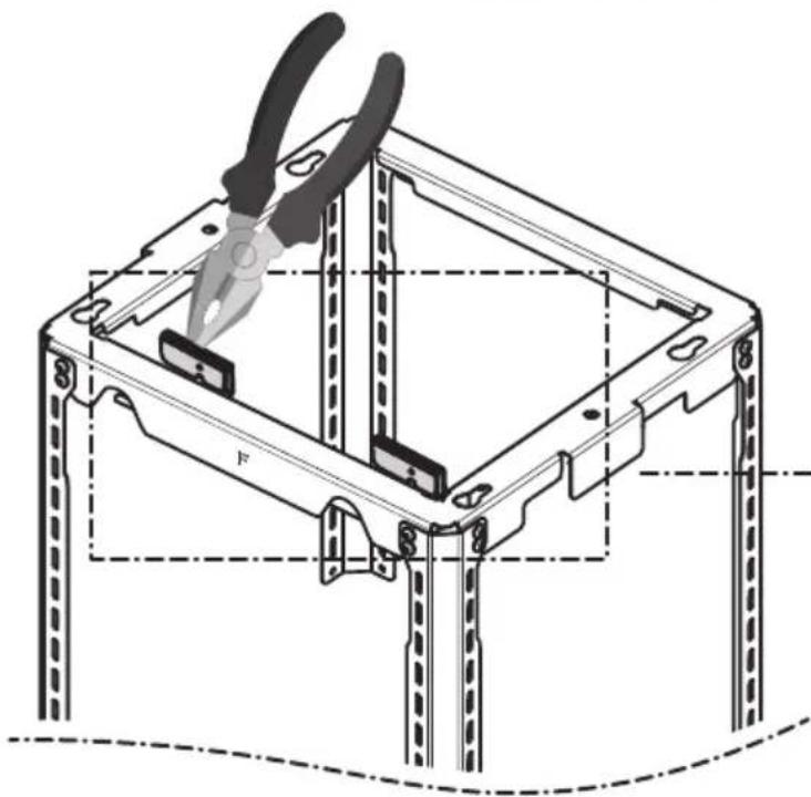
natural_image
Technical line drawing of a mechanical assembly with pliers and structural supports (no text or symbols)2x
natural_image
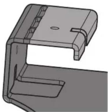
3D technical drawing of a mechanical bracket component (no text or symbols)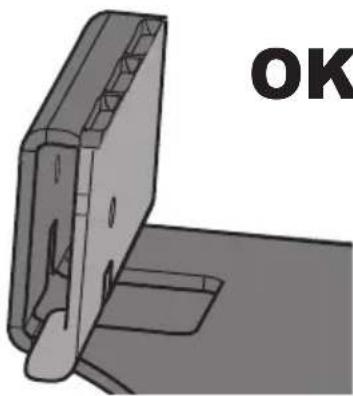
natural_image
3D mechanical part with mounting holes and a labeled 'OK' (no other text or symbols)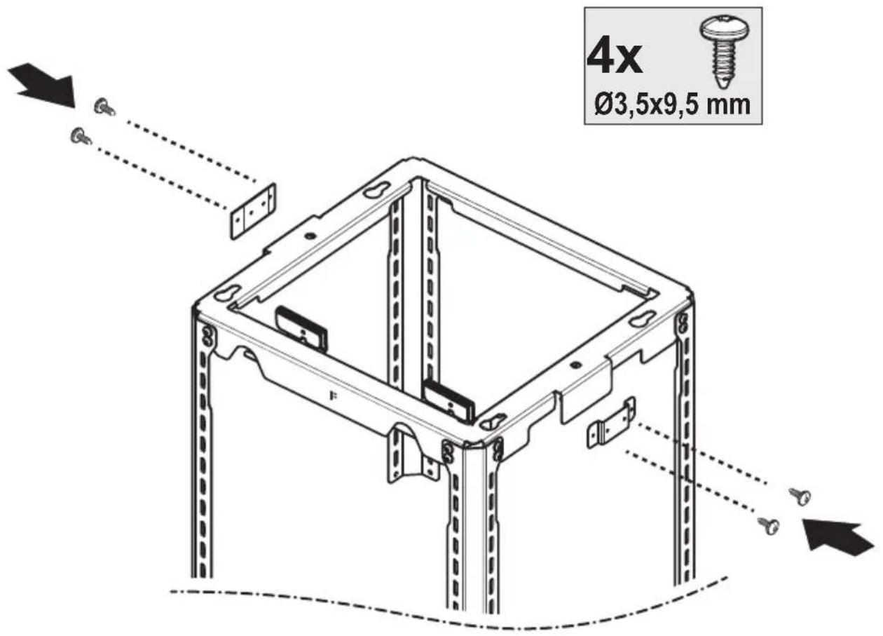
13
natural_image
Technical illustration of a computer case with a hand inserting a cable into a drive housing (no text or symbols present)14
natural_image
Technical line drawing of a mechanical frame structure with mounting holes and a downward arrow indicating assembly (no text or symbols)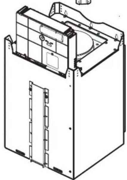
natural_image
Technical line drawing of a mechanical device housing with internal components and mounting brackets (no text or symbols)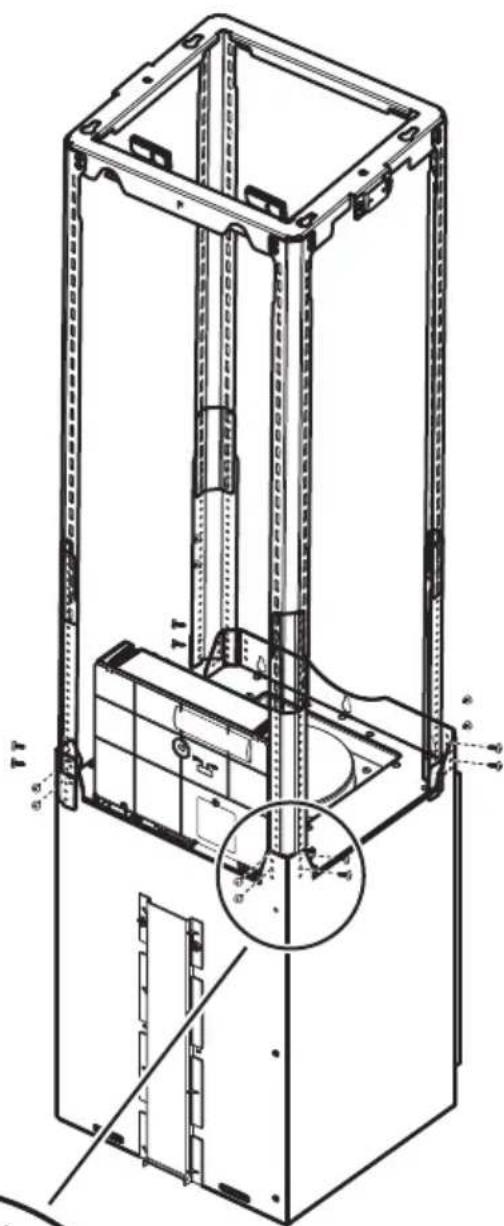
natural_image
Simple line drawing of a house with an upward arrow and a diagonal line crossing it (no text or symbols)
natural_image
Technical line drawing of a mechanical frame structure with dimension labels H and F (no text or symbols beyond labels)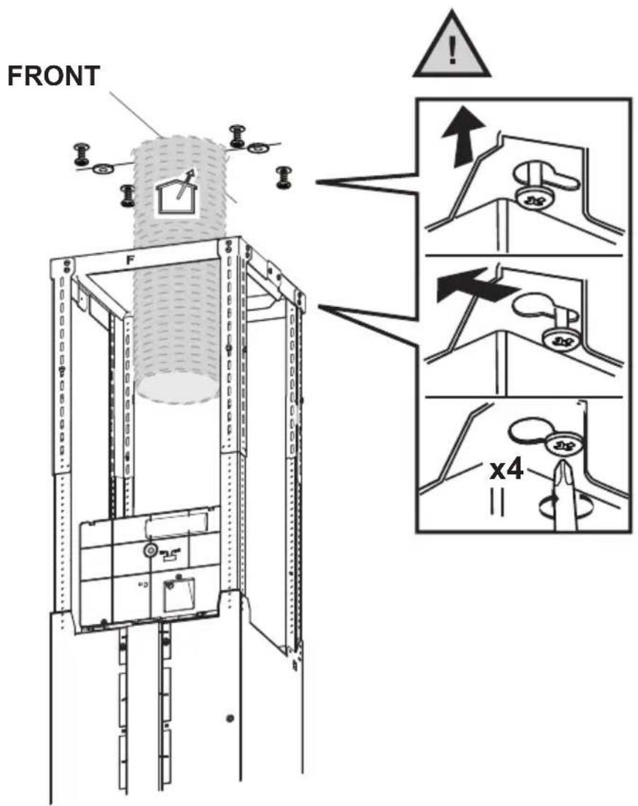
natural_image
Simple line drawing of a house with a circular arrow inside, symbolizing refresh or cycle (no text or symbols)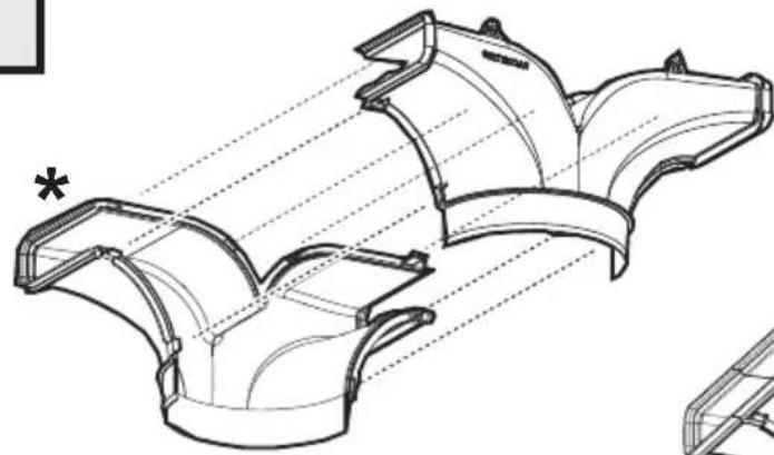
natural_image
Technical line drawing of a mechanical component with multiple curved surfaces and alignment lines (no text or symbols)Clack!
natural_image
Technical line drawing of a V-groove pipe fitting (no text or symbols)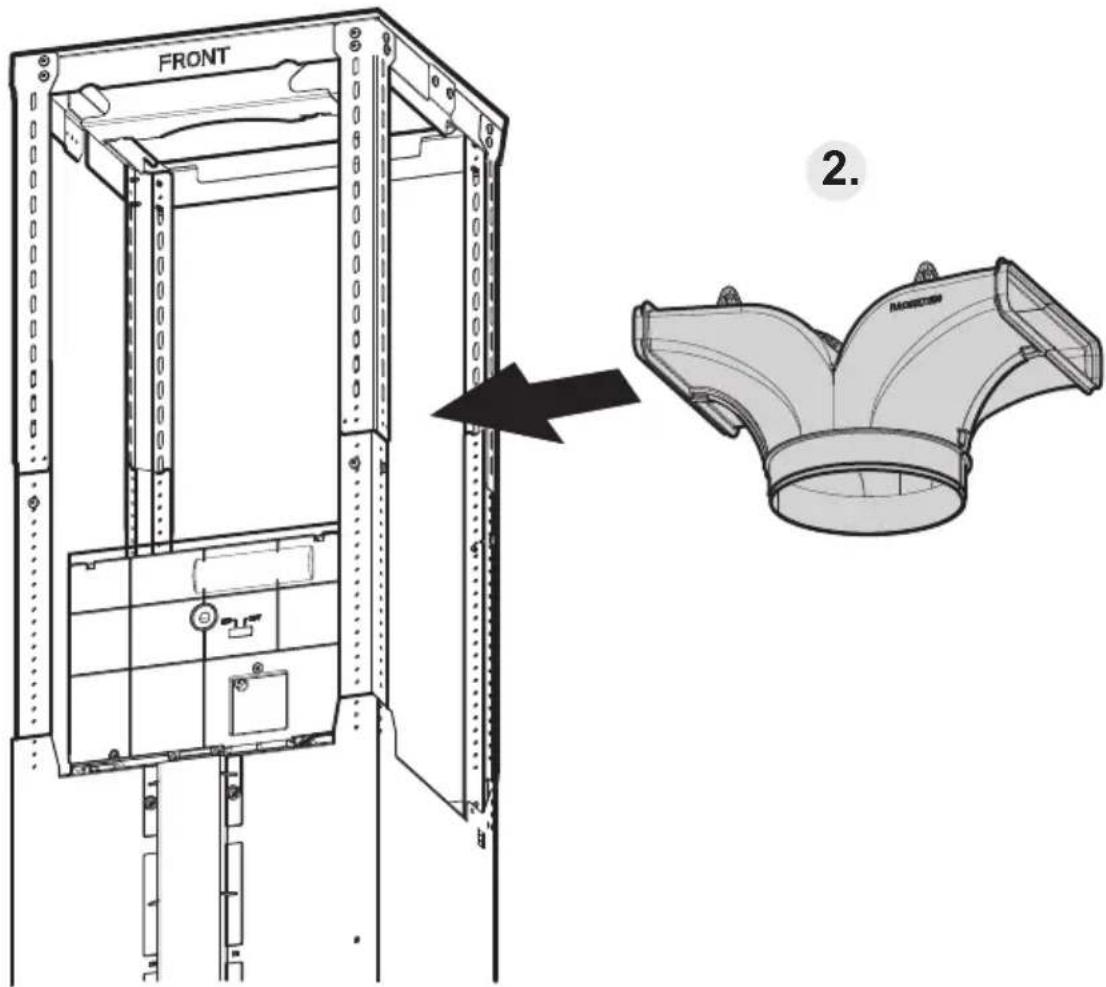
natural_image
Simple line drawing of a warehouse with a circular arrow inside, symbolizing refresh or move (no text or symbols)
natural_image
Technical diagram of a mechanical assembly with mounting brackets and a curved channel, showing no text or symbols.3.
20.1
natural_image
Technical line drawing of a multi-level industrial lifting or lifting system with structural framework (no text or symbols)
natural_image
Technical diagram of a server rack with an open panel and a highlighted frame, showing internal components and wiring (no text or symbols)
natural_image
Simple line drawing of a hand holding a document or paper (no text or symbols)9
natural_image
Diagram of a rectangular frame with dashed arrows indicating rotational motion (no text or symbols)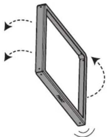
natural_image
Diagram of a rectangular frame with dashed arrows indicating rotational motion (no text or symbols)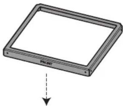
natural_image
Diagram of a rectangular device with label 'PH.NET' and a downward arrow, no readable text or symbols beyond the label.8x
∅3,5x9,5 mm
natural_image
Technical line drawing of a multi-level industrial lifting or storage unit structure (no text or symbols)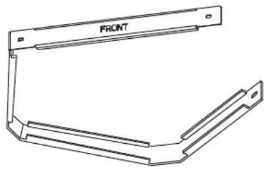
natural_image
Technical line drawing of a mechanical bracket with 'FRONT' label (no other text or symbols)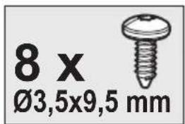

natural_image
Technical line drawing of a cabinet or elevator assembly with a circular icon showing a house with a circular symbol (no text or labels present)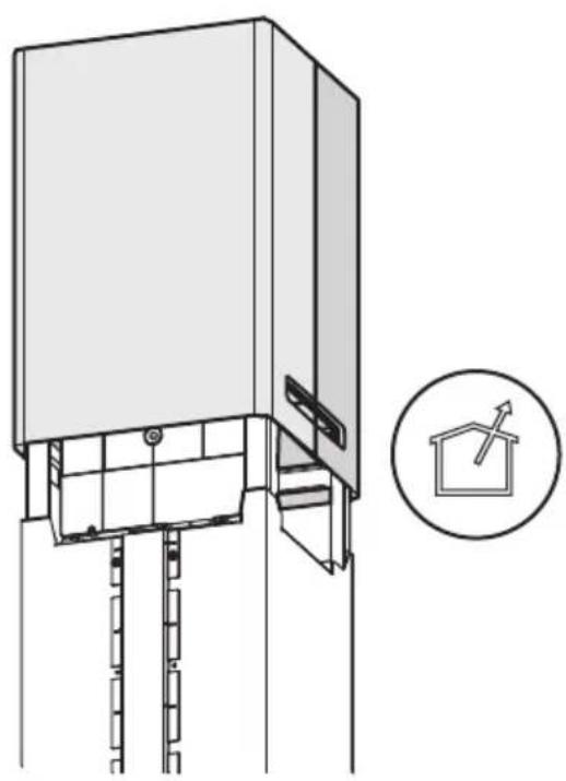
natural_image
Technical line drawing of a mechanical device with a magnified inset showing a house symbol (no text or labels)
natural_image
Technical line drawing of a mechanical assembly with a bracket and internal components (no text or symbols)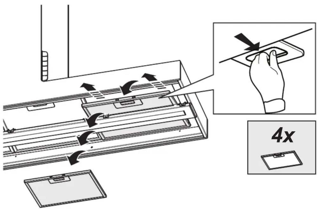
natural_image
Technical line drawing of a device assembly showing internal components and a downward arrow indicating motion (no text or symbols present)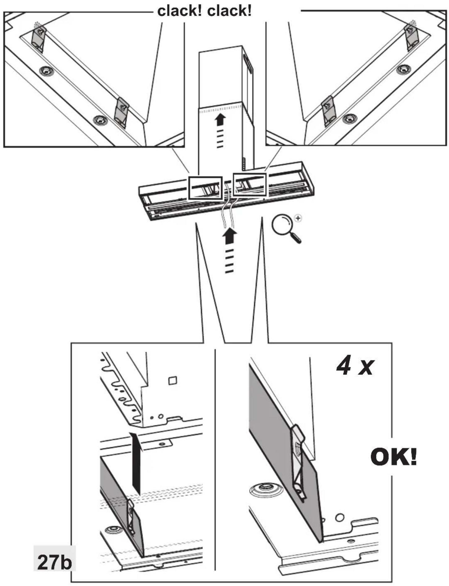
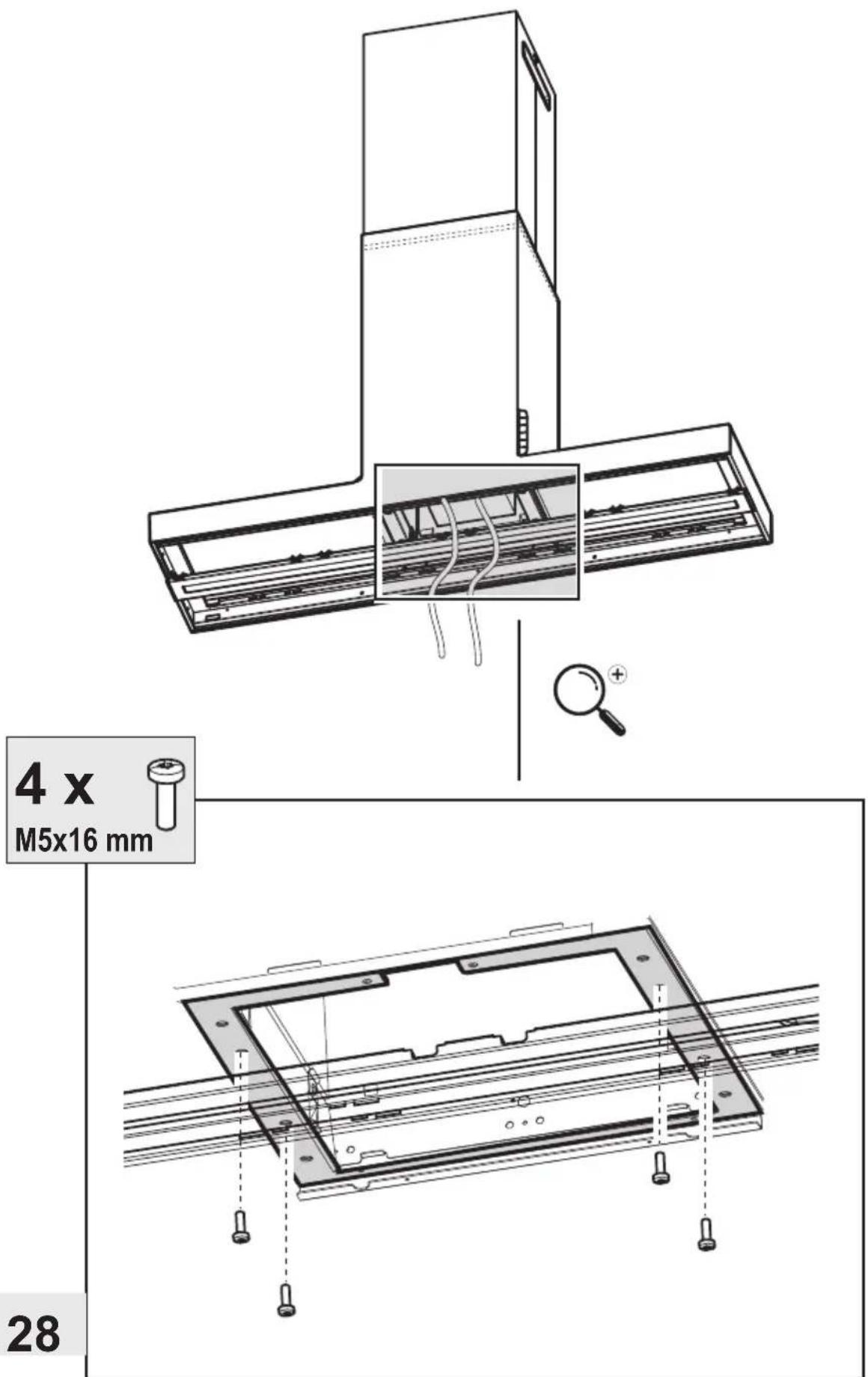
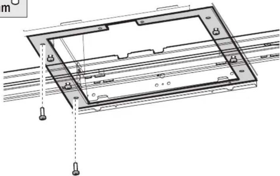
4x
M5x16 mm
natural_image
Technical diagram showing a mechanical assembly with a bracket and a labeled component R (no text or symbols present)
natural_image
Diagram of a server rack with internal components and directional arrows indicating rotation (no text or symbols)
natural_image
Diagram of a vehicle inside a circular frame with motion arrows indicating clockwise motion (no text or symbols)2x
M5x16 mm

29a
natural_image
Technical line drawing of a mechanical assembly with mounting holes and structural beams (no text or symbols)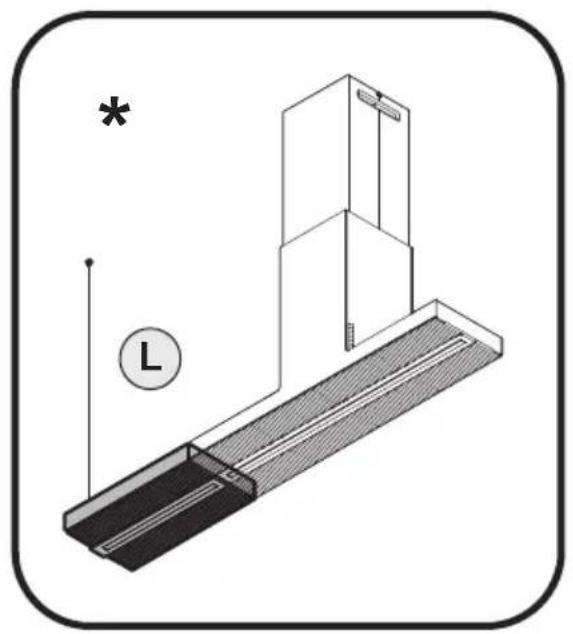
natural_image
Technical line drawing of a mechanical assembly with a bracket and shaft, no text or symbols present
natural_image
Diagram of a server rack with internal components and directional arrows indicating rotation (no text or symbols)
natural_image
Diagram of a car with motion arrows indicating speed or direction (no text or symbols)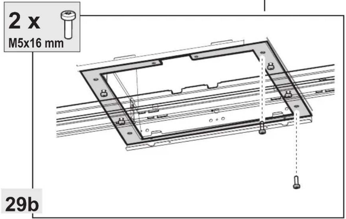
29b
2x
∅3,5x9,5 mm
natural_image
Technical diagram showing a mechanical assembly with a bracket and a vertical rod, no text or symbols present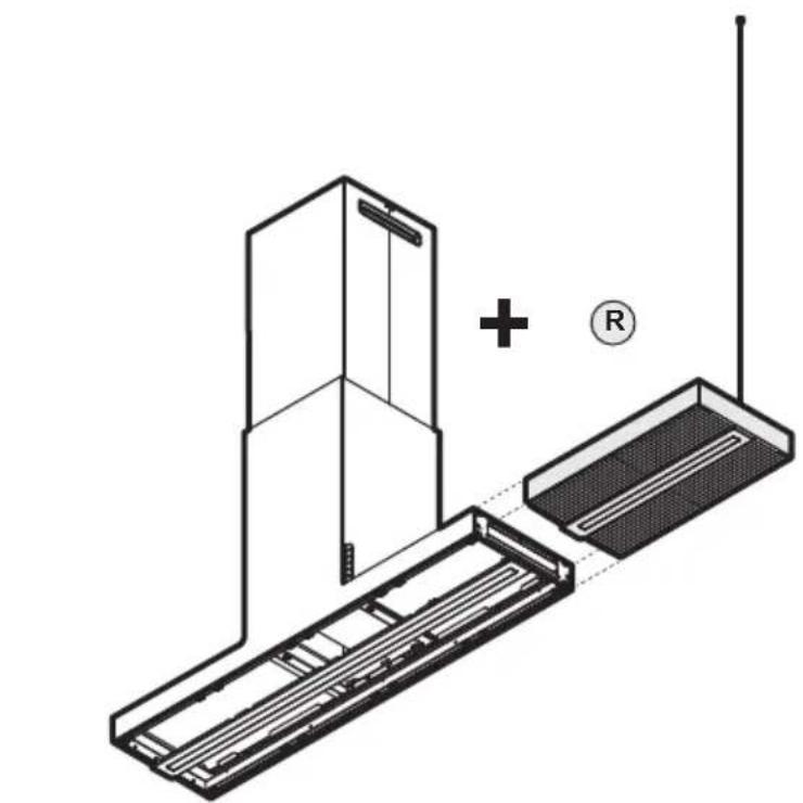
natural_image
Technical line drawing of a device with a plus sign and antenna, no text or symbols present
33-35-36-37-38-39-40-41-41a-42-43-44-45-46-48-49
natural_image
Technical line drawing of a mechanical device with a base and vertical rod, no text or symbols present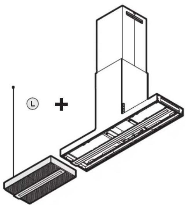
natural_image
Technical line drawing of a device with an antenna, showing internal components and a plus symbol (no text or labels)
34-34a-35-36-37-38-39-40-41-41a-42-43-44-45-47-48-49
natural_image
Technical diagram showing a mechanical assembly with a bracket and a vertical rod, no text or symbols present.
natural_image
Technical line drawing of a server rack with an inset magnified view showing internal components (no text or symbols)
natural_image
Technical line drawing of a mechanical assembly with mounting brackets and mounting holes (no text or symbols)
natural_image
Technical diagram of a mechanical assembly with a labeled component (no text or symbols present)
natural_image
Simple black arrow pointing right on white background (no text or symbols)
37
natural_image
Technical line drawing of a mechanical assembly with a magnified inset showing internal components (no text or symbols)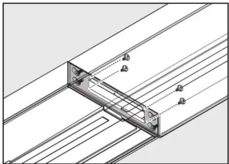
natural_image
Technical line drawing of a structural assembly with beams and supports (no text or symbols)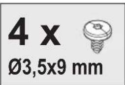
natural_image
Technical diagram of a ship's deck structure with motion arrows and a circular inset showing a boat's view (no text or symbols)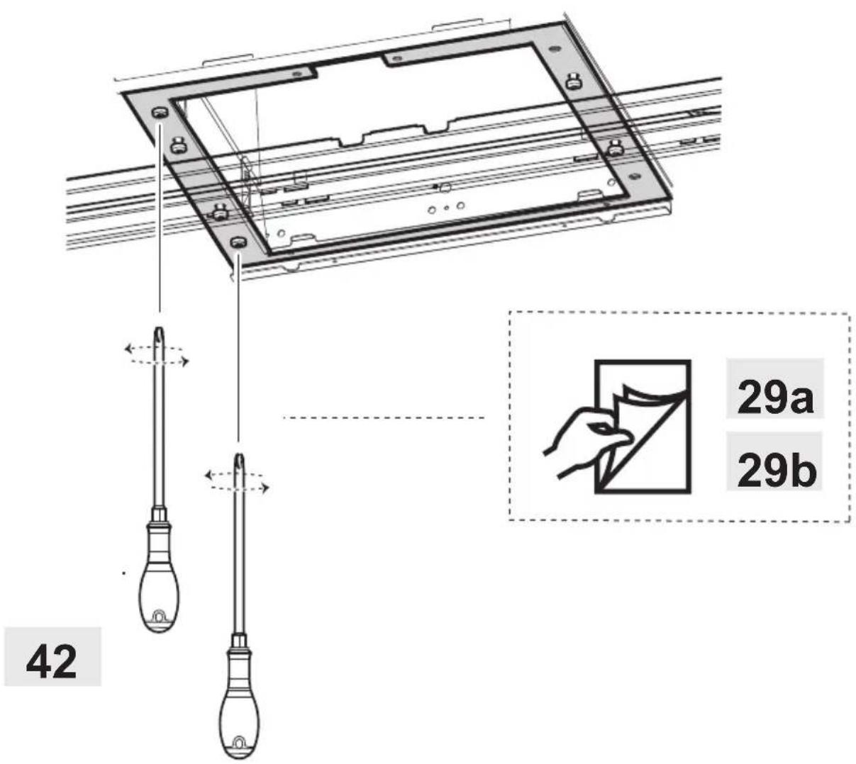
natural_image
Technical diagram of a rectangular electronic device with internal components and directional arrows indicating flow or movement (no text or symbols present)
natural_image
Diagram showing a structural joint with an upward arrow indicating force or direction, no text or symbols present
natural_image
Diagram of a structural joint or panel connection with arrows indicating direction (no text or symbols present)
natural_image
Technical diagram showing a mechanical assembly with a bracket and a vertical rod, no text or symbols present.
natural_image
Technical line drawing of a mechanical assembly with two views (top and side), showing internal components and wiring connections without any text or symbols.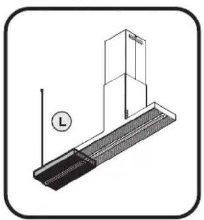
natural_image
Technical line drawing of a mechanical assembly with a vertical rod and base plate, no text or symbols present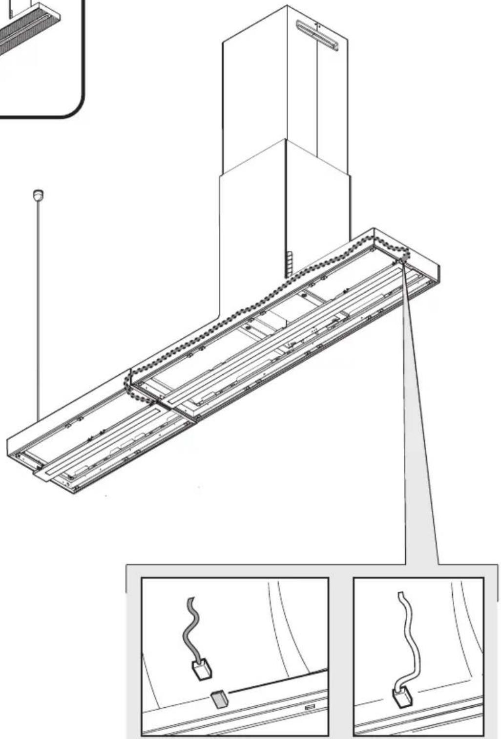
natural_image
Technical line drawing of a mechanical assembly with two views (top and side), no visible text or symbols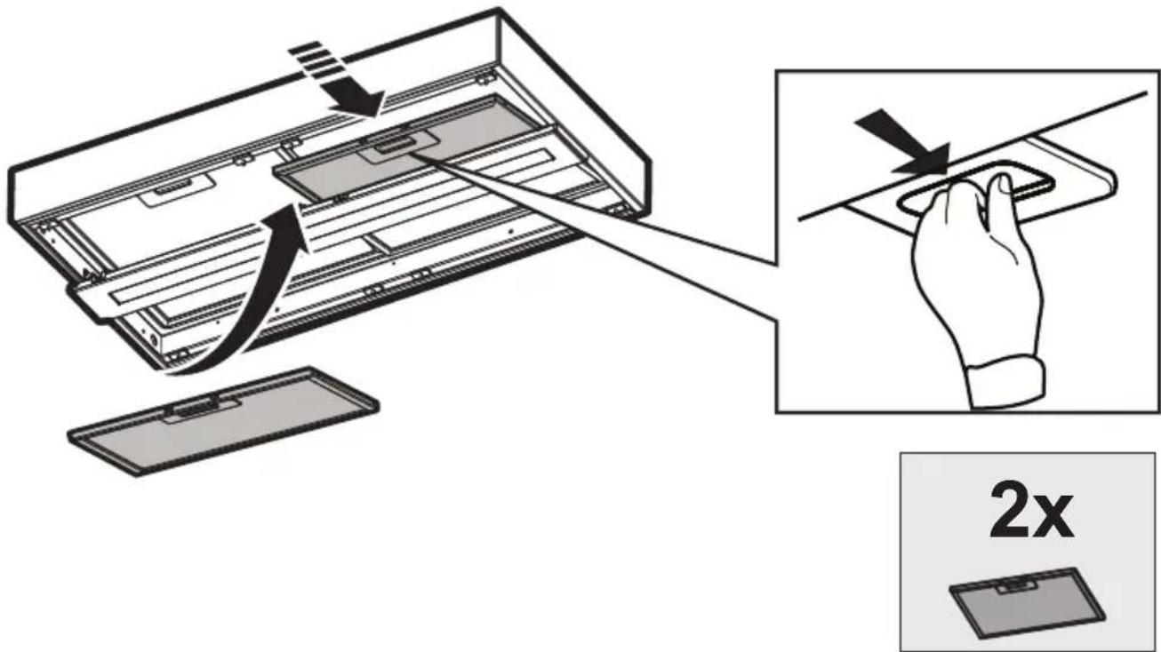
48
natural_image
Technical line drawing of a mechanical component with grooves and a central bracket (no text or symbols)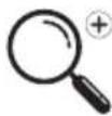
49
natural_image
Technical line drawing of a mechanical assembly with two views (top and side), showing internal components and a vertical pole (no text or symbols)
natural_image
Simple line drawing of a house with a circular arrow inside, symbolizing refresh or cycle (no text or symbols)
natural_image
Simple line drawing of a house with a circular arrow inside, symbolizing refresh or cycle (no text or symbols)
natural_image
Technical illustration of a mechanical assembly with a magnified inset showing a component being processed (no text or symbols present)EN - Instruction on mounting and use
Closely follow the instructions set out in this manual. All responsibility, for any eventual inconveniences, damages or fires caused by not complying with the instructions in this manual, is declined. This appliance is intended to be used in household and similar application such as: - staff kitchen areas in shop, offices and other working environments; - farm houses; - by clients in hotels, motels and other residential type environments; - bed and breakfast type environments.
The hood can look different to that illustrated in the drawings in this booklet. The instructions for use, maintenance and installation, however, remain the same.
- It is important to conserve this booklet for consultation at any moment. In the case of sale, cession or move, make sure it is together with the product.
- Read the instructions carefully: there is important information about installation, use and safety.
- Do not carry out electrical or mechanical variations on the product or on the discharge conduits.
- Before proceeding with the installation of the appliance verify that there are no damaged all components. Otherwise contact your dealer and do not proceed with the installation.
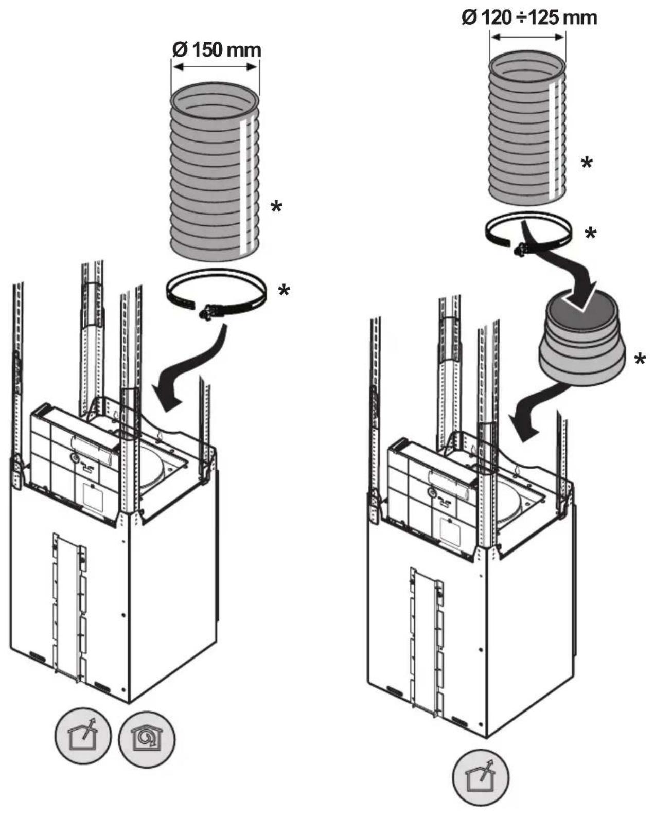
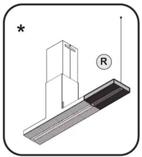
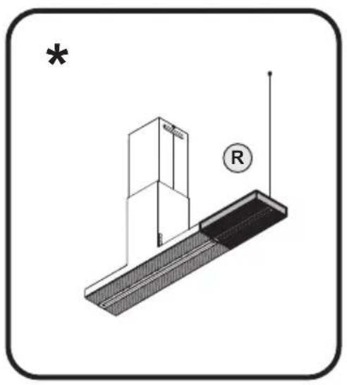
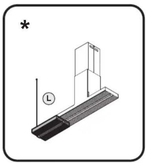
Note: The parts marked with the symbol "(*)" are optional accessories supplied only with some models or otherwise not supplied, but available for purchase.

Caution
- Before any cleaning or maintenance operation, disconnect hood from the mains by removing the plug or disconnecting the mains electrical supply.
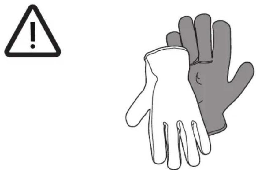
• Always wear work gloves for all installation and maintenance operations. - This appliance can be used by children aged from 8 years and above and persons with reduced physical, sensory or mental capabilities or lack of experience and knowledge if they have been given supervision or instruction concerning use of the appliance in a safe way and understand the hazards involved.
- Children shall not be allowed to tamper with the controls or play with the appliance.
- Cleaning and user maintenance shall not be made by children without supervision.
- The premises where the appliance is installed must be sufficiently ventilated, when the kitchen hood is used together with other gas combustion devices or other fuels.
- The hood must be regularly cleaned on both the inside and outside (AT LEAST ONCE A MONTH).
- This must be completed in accordance with the maintenance instructions provided. Failure to follow the instructions provided regarding the cleaning of the hood and filters will lead to the risk of fires.
- Do not flambé under the range hood.
- For lamp replacement use only lamp type indicated in the Maintenance/Replacing lamps section of this manual.
The use of exposed flames is detrimental to the filters and may cause a fire risk, and must therefore be avoided in all circumstances.
Any frying must be done with care in order to make sure that the oil does not overheat and ignite.
CAUTION: Accessible parts of the hood may become hot when used with cooking appliances.
- Do not connect the appliance to the mains until the installation is fully complete.
- With regards to the technical and safety measures to be adopted for fume discharging it is important to closely follow the regulations provided by the local authorities.
- The air must not be discharged into a flue that is used for exhausting fumes from appliance burning gas or other fuels.
- Do not use or leave the hood without the lamp correctly mounted due to the possible risk of electric shocks.
- Never use the hood without effectively mounted grids.
- The hood must NEVER be used as a support surface unless specifically indicated.
-
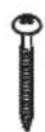
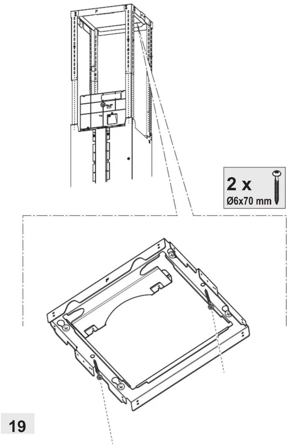
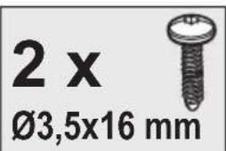
Use only the fixing screws supplied with the product for installation or, if not supplied, purchase the correct screws type.
-
Use the correct length for the screws which are identified in the Installation Guide.
• In case of doubt, consult an authorized service assistance center or similar qualified person.
WARNING!
- Failure to install the screws or fixing device in accordance with these instructions may result in electrical hazards.
-
Do not use with a programmer, timer, separate remote control system or any other device that switches on automatically.
-
This appliance is marked according to the European directive 2012/19/EC on Waste Electrical and Electronic Equipment (WEEE).
- By ensuring this product is disposed of correctly, you will help prevent potential negative consequences for the environment and human health, which could otherwise be caused by inappropriate waste handling of this product.

- The symbol ■ the product, or on the documents accompanying the product, indicates that this appliance may not be treated as household waste. Instead it should be taken to the appropriate collection point for the recycling of electrical and electronic equipment. Disposal must be carried out in accordance with local environmental regulations for waste disposal.
- For further detailed information regarding the process, collection and recycling of this product, please contact the appropriate department of your local authorities or the local department for household waste or the shop where you purchased this product.
Appliance designed, tested and manufactured according to:
• Safety: EN/IEC 60335-1; EN/IEC 60335-2-31, EN/IEC 62233
• Performance: EN/IEC 61591; ISO 5167-1; ISO 5167-3; ISO 5168; EN/IEC 60704-1; EN/IEC 60704-2-13; EN/IEC 60704-3; ISO 3741; EN 50564; IEC 62301.
- EMC: EN 55014-1; CISPR 14-1; EN 55014-2; CISPR 14-2; EN/IEC 61000-3-2; EN/IEC 61000-3-3. Suggestions for a correct use in order to reduce the environmental impact: Switch ON the hood at minimum speed when you start cooking and kept it running for few minutes after cooking is finished. Increase the speed only in case of large amount of smoke and vapor and use boost speed(s) only in extreme situations. Replace the charcoal filter(s) when necessary to maintain a good odor reduction efficiency. Clean the grease filter(s) when necessary to maintain a good grease filter efficiency. Use the maximum diameter of the ducting system indicated in this manual to optimize efficiency and minimize noise.
Use
The hood is designed to be used either for exhausting or filter version.

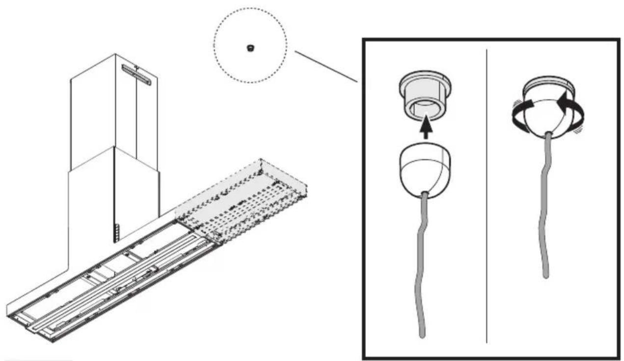
Extraction version
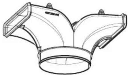
In this case the fumes are conveyed outside of the building by means of a special pipe connected with the connection ring located on top of the hood.
CAUTION!
The exhausting pipe is not supplied and must be purchased apart.
Diameter of the exhausting pipe must be equal to that of the connection ring.
CAUTION!
If the hood is supplied with active charcoal filter, then it must be removed.
Connect the hood and discharge holes on the walls with a diameter equivalent to the air outlet (connection flange).
Using the tubes and discharge holes on walls with smaller dimensions will cause a diminution of the suction performance and a drastic increase in noise.
Any responsibility in the matter is therefore declined.
! Use a duct of the minimum indispensable length.
! Use a duct with as few elbows as possible (maximum elbow angle: 90°).
! Avoid drastic changes in the duct cross-section.

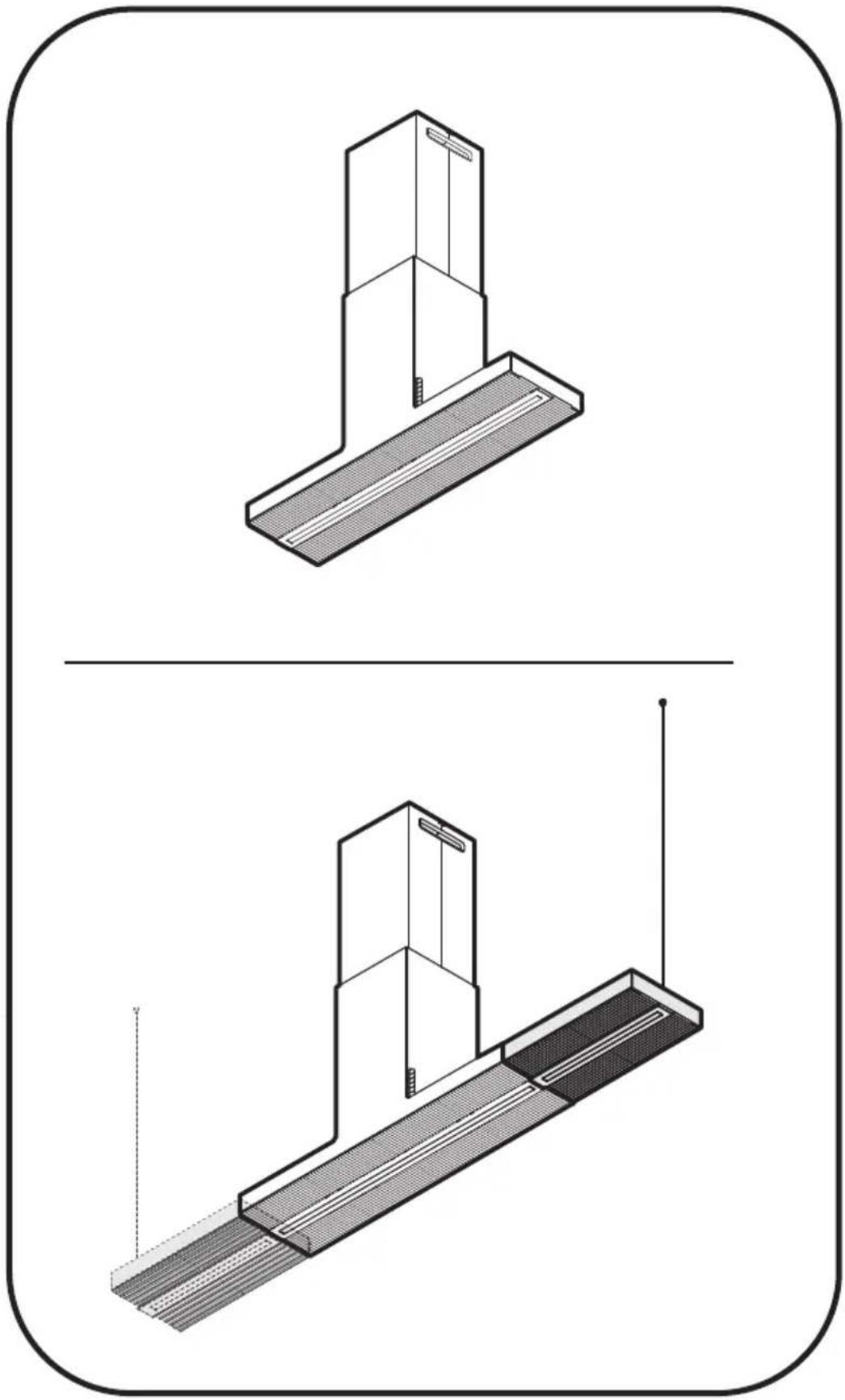
Filtration version
The aspirated air will be degreased and deodorised before being fed back into the room.
In order to use the hood in this version, you have to install a system of additional filtering based on activated charcoal.
Installation
The minimum distance between the supporting surface for the cooking equipment on the hob and the lowest part of the range hood must be not less than 60cm from electric cookers and 65cm from gas or mixed cookers.
If the instructions for installation for the gas hob specify a greater distance, this must be adhered to.

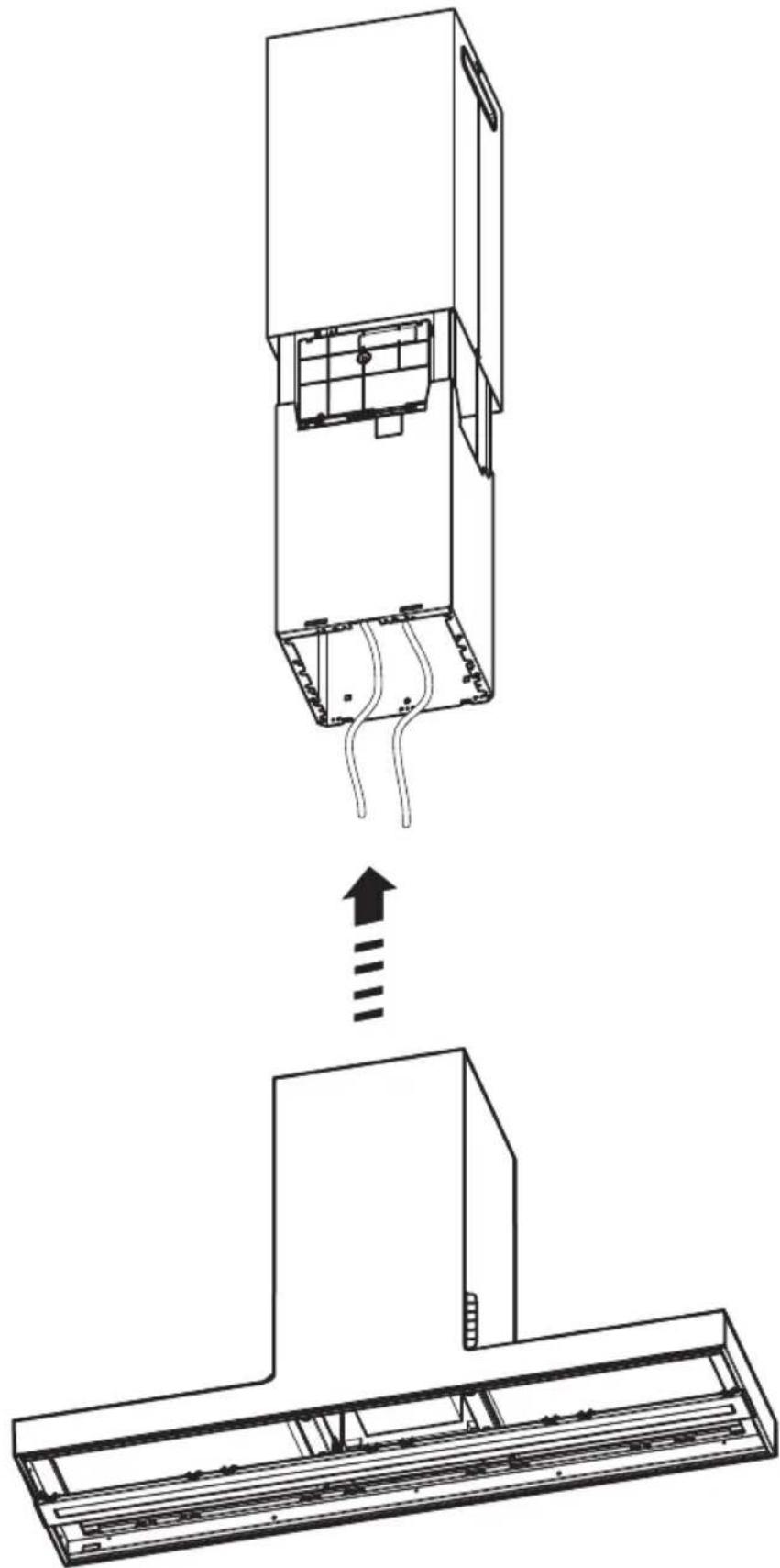
Electrical connection
The mains power supply must correspond to the rating indicated on the plate situated inside the hood. If provided with a plug connect the hood to a socket in compliance with current regulations and positioned in an accessible area, after installation. If it not fitted with a plug (direct mains connection) or if the plug is not located in an accessible area, after installation, apply a double pole switch in accordance with standards which assures the complete disconnection of the mains under conditions relating to over-current category III, in accordance with installation instructions.

WARNING!
Before re-connecting the hood circuit to the mains supply and checking the efficient function, always check that the mains cable is correctly assembled.
The hood is provided with a special power cable; if the cable is damaged, request a new one from Technical Service.
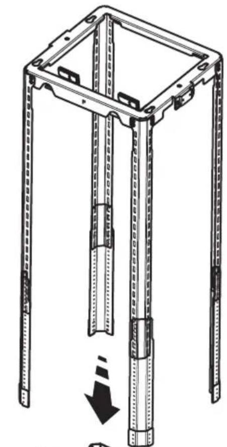
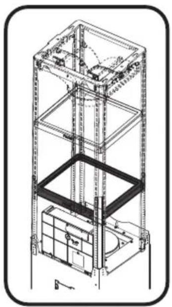
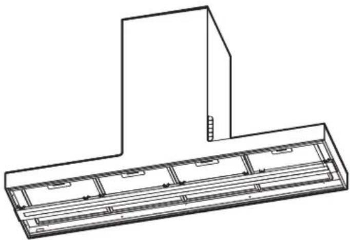
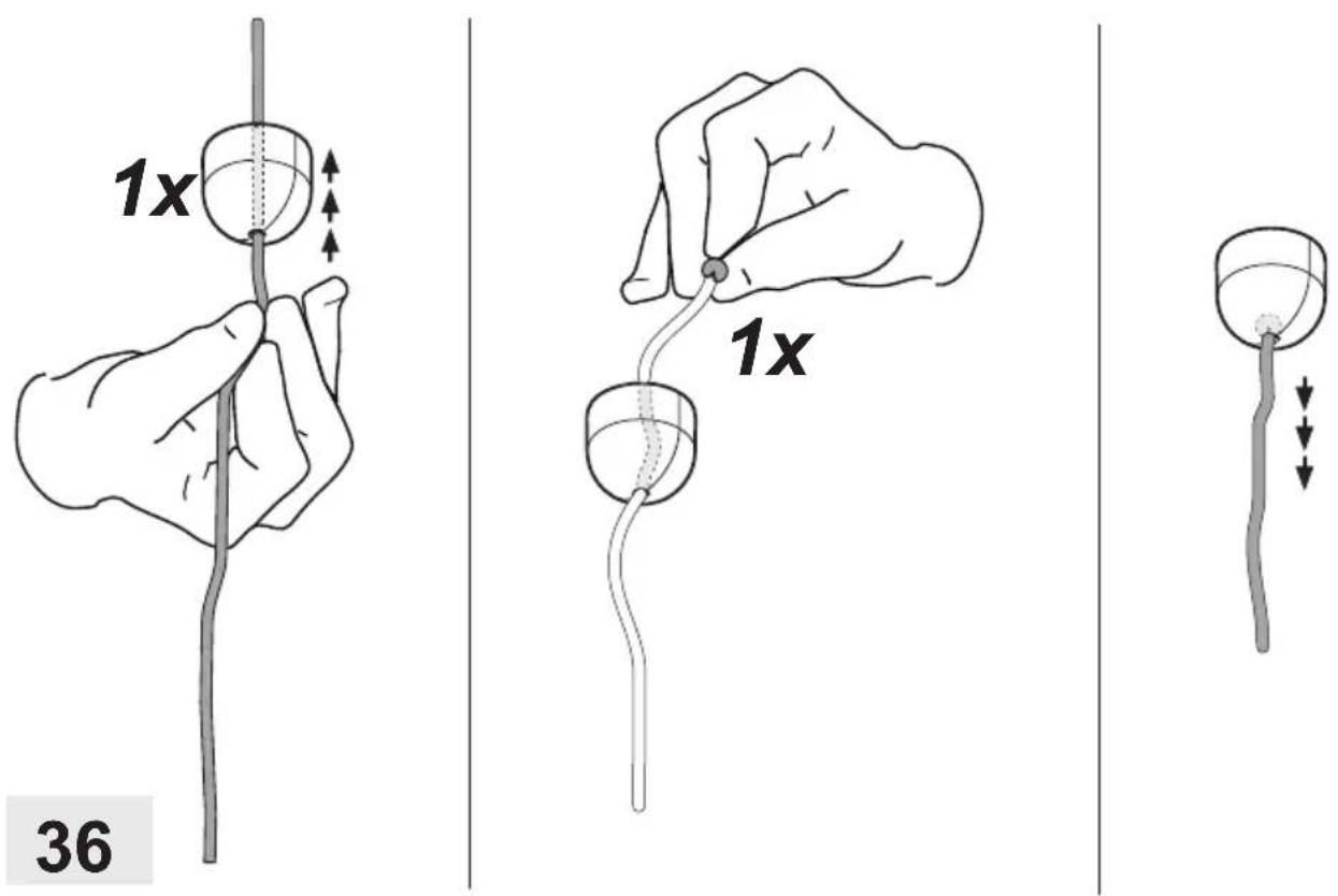
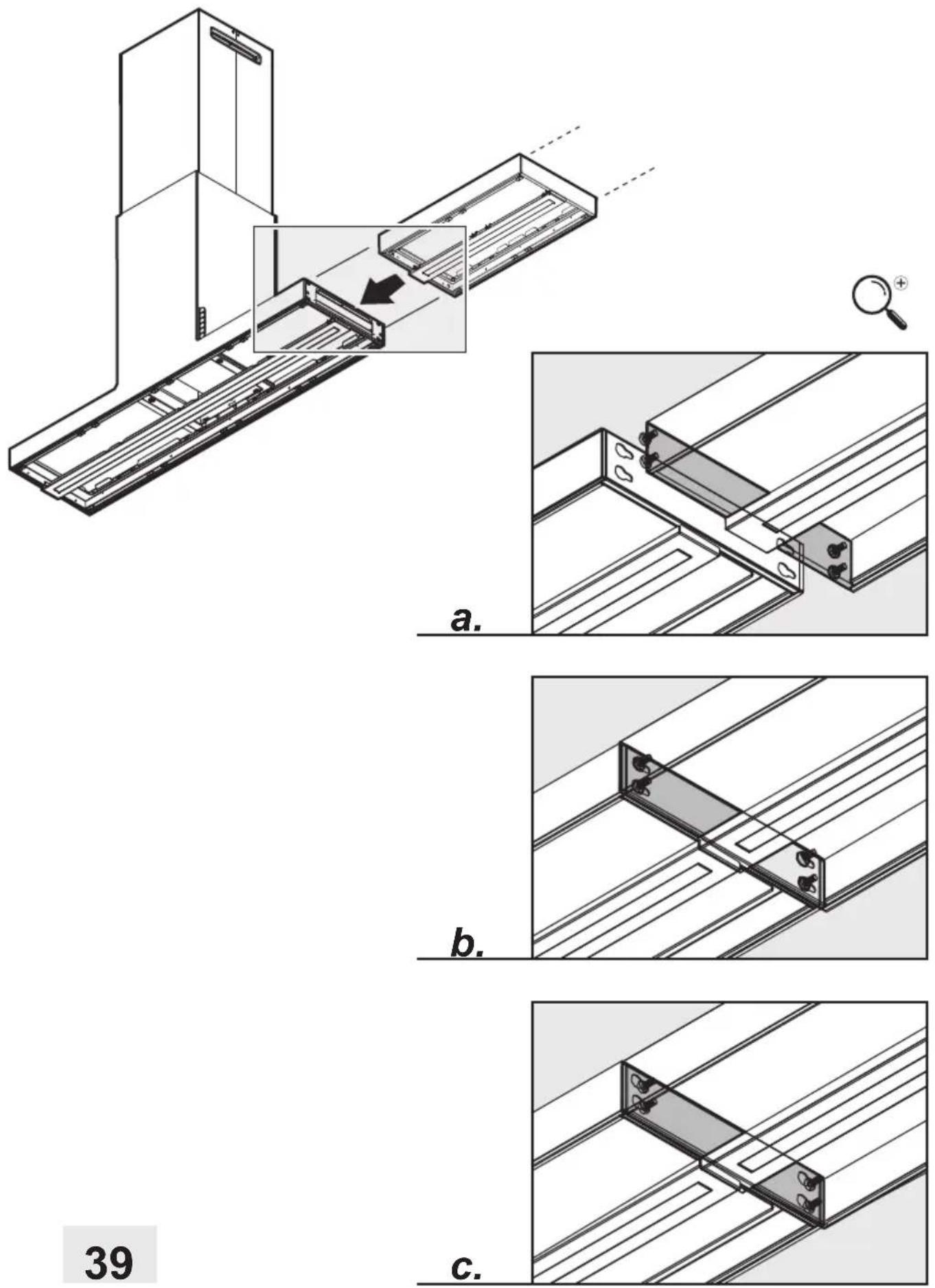
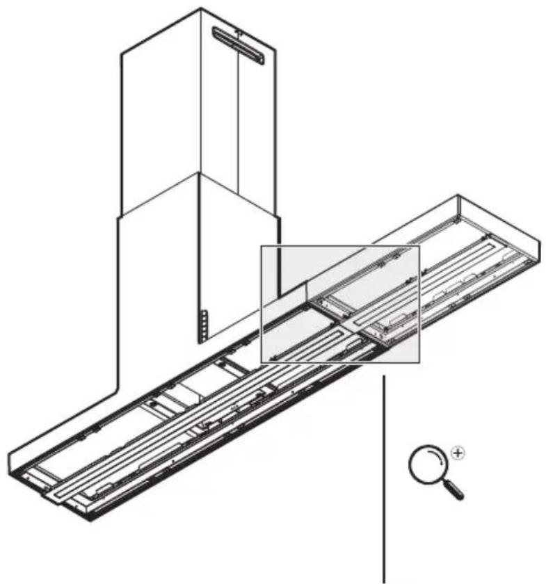
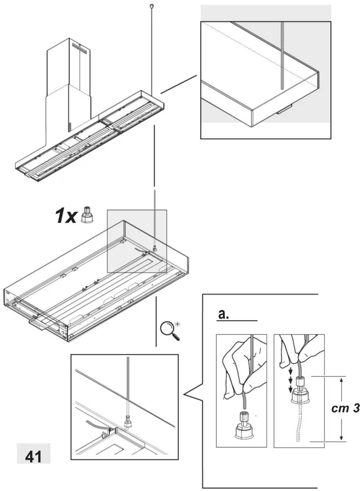
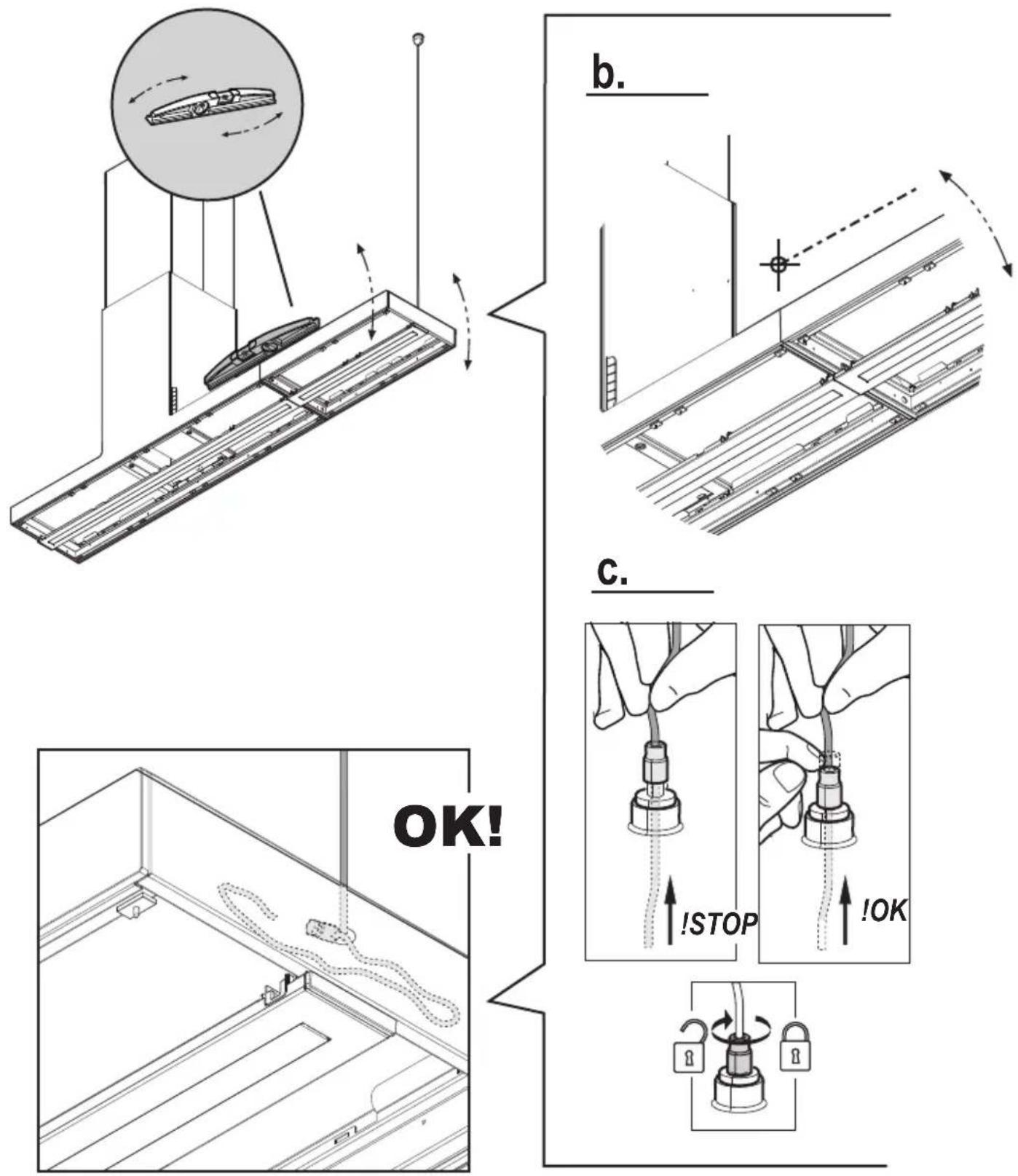
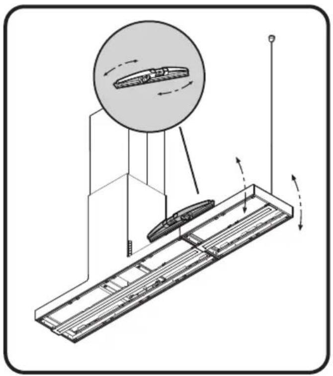
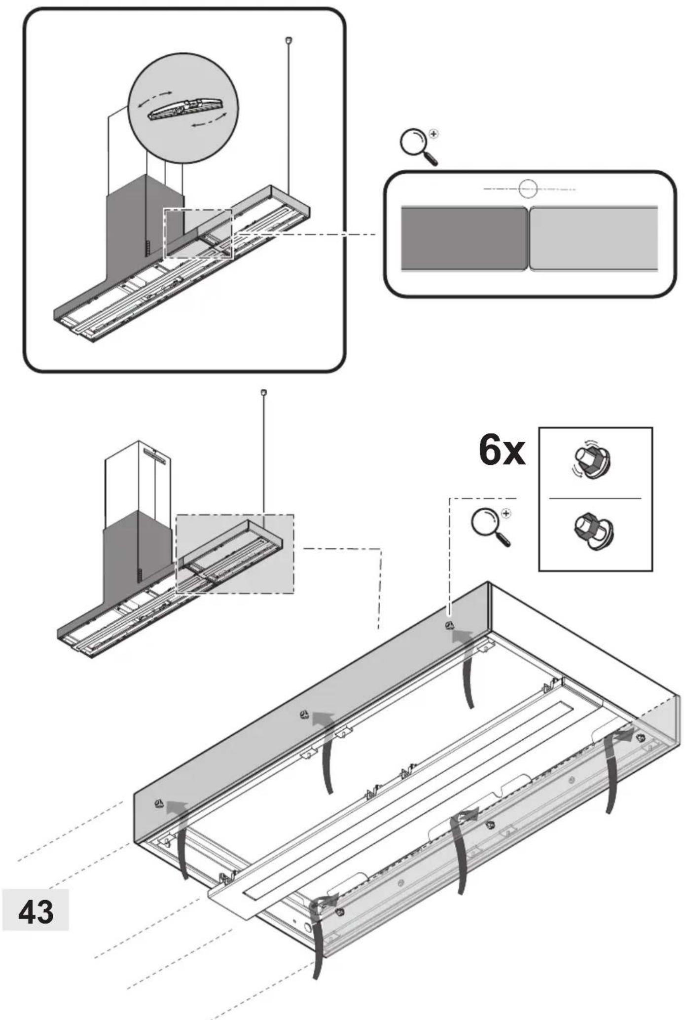
Mounting
Before beginning installation:
- Check that the product purchased is of a suitable size for the chosen installation area.
- Remove the charcoal (*) filter/s if supplied (see also relative paragraph). This/these is/are to be mounted only if you want lo use the hood in the filtering version.
- Check (for transport reasons) that there is no other supplied material inside the hood (e.g. packets with screws (*), guarantees (*), etc.), eventually removing them and keeping them.
Very heavy product; hood handling and installation must be carried out by at least two persons.
Operation
ON/OFF light button
Press to turn the cooktop light on or off.
"BOOST" speed selection key
1st push : to enable the intensive suction speed "BOOST 1", timed for 30 minutes this prolonged timing has been designed to guarantee a suitable cooking time for preparations that release high amounts of smoke during cooking
Note : after 30 minutes, the hood will return to the suction speed previously set
2nd push ("BOOST 1" activated): to activate the intensive suction speed "BOOST 2", timed for 7 minutes
Note: after 7 minutes, the hood will return to the previously set suction speed
3rd push ("BOOST 2" activated): to exit the function and return to the speed previously set.
Note: the speed key previously set remains lit during BOOST operation.
Speed selection key 3
Push to activate the high speed (suction power)
Speed selection key 2
Push to activate the average speed (suction power)
Speed selection key 1
Push to enable the low speed (suction power)
Power button
Push to switch on the hood and enable speed selection;
if pushed while the motor is running, the latter will stop
Note: if no function is activated within 10 seconds, the hood turns off.
Filter Saturation indicator lights
The hood signals at regular intervals that the filters must be serviced.


Keys and lit and flashing very slowly: service the grease filter.

Keys and lit and flashing quickly: service the odour filter.
Note: The filter saturation warning signal is visible within the first 10 seconds after the hood is switched on.
Reset filter saturation indicator:
Press and hold the keys and

The keys will flash quickly to confirm that reset has been completed
Activation of filter saturation indicators
Note: this operation must be performed with the hood off.
- Grease filter
Push and hold down the keys activate the function


the keys light up flashing very slowly, indicating that the grease filter indicator can be activated
Note: Push the keys deactivate
- Odour filter
Push and hold down the keys and activate the function

the keys light up flashing quickly, indicating that the odour filter indicator can be activated (normally deactivated)
Note: Push the keys deactivate

Maintenance
Cleaning
Clean using ONLY a cloth dampened with neutral liquid detergent. DO NOT CLEAN WITH TOOLS OR INSTRUMENTS. Do not use abrasive products. DO NOT USE ALCOHOL!
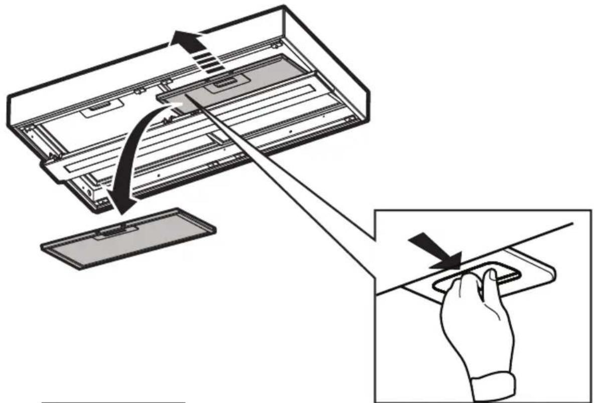
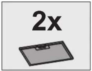
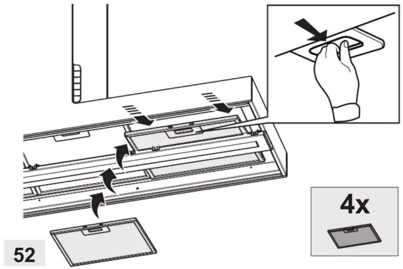
Grease filter
Fig. 38 / 48-52
Traps cooking grease particles.
This must be cleaned once a month (or when the filter saturation indication system – if envisaged on the model in possession – indicates this necessity) using non aggressive detergents, either by hand or in the dishwasher, which must be set to a low temperature and a short cycle.
When washed in a dishwasher, the grease filter may discolor slightly, but this does not affect its filtering capacity.
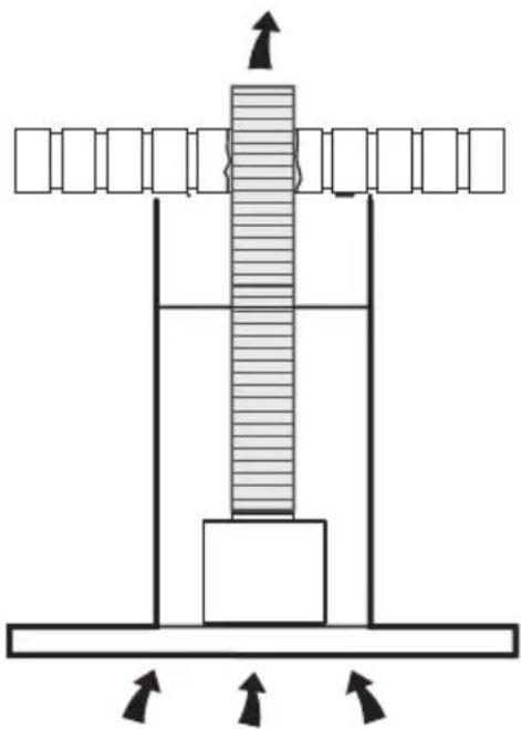
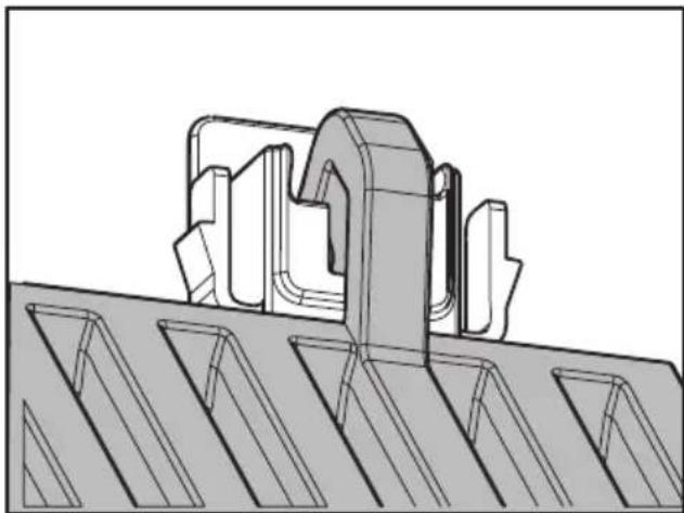
To remove the grease filter, pull the spring release handle.
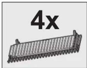
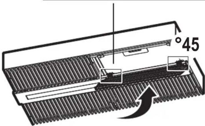
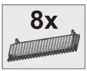
Charcoal filter (filter version only)
Fig. 51
It absorbs unpleasant odors caused by cooking.
The charcoal filter can be washed once every two months (or when the filter saturation indication system – if envisaged on the model in possession – indicates this necessity) using hot water and a suitable detergent, or in a dishwasher at 65^ C (if the dishwasher is used, select the full cycle function and leave dishes out).
Eliminate excess water without damaging the filter, then put it in the oven for 10 minutes at 100^ C to dry completely. Replace the mattress every 3 years and when the cloth is damaged.
Replacing lamps
The hood is equipped with a lighting system based on LED technology.
The LEDs guarantee an optimum lighting, a duration up to 10 times as long as the traditional lamps and allow to save 90% electrical energy.
For replacement, contact the technical service.


- EN - Instruction on mounting and use
- Caution
- WARNING!
- Use
- Extraction version
- CAUTION!
- Filtration version
- Installation
- Electrical connection
- Mounting
- Before beginning installation:
- Operation
- ON/OFF light button
- "BOOST" speed selection key
- Speed selection key 3
- Speed selection key 2
- Speed selection key 1
- Power button
- Filter Saturation indicator lights
- Reset filter saturation indicator:
- Activation of filter saturation indicators
- - Grease filter
- - Odour filter
- Maintenance
- Cleaning
- Grease filter
- Charcoal filter (filter version only)
- Replacing lamps
Brand : ELICA
Model : Haiku I 32 WH
Category : Iron