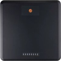
DTE930 - Barcode scanner IFM - Free user manual and instructions
Find the device manual for free DTE930 IFM in PDF.


User questions about DTE930 IFM
0 question about this device. Answer the ones you know or ask your own.
Ask a new question about this device
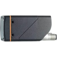
Download the instructions for your Barcode scanner in PDF format for free! Find your manual DTE930 - IFM and take your electronic device back in hand. On this page are published all the documents necessary for the use of your device. DTE930 by IFM.
USER MANUAL DTE930 IFM
Operating instructions
RFID UHF Reader
DTE830
DTE930
DTE939
Contents
1 Preliminary note 3
1.1 Symbols used 3
1.2 Warnings used 3
1.3 Legal and copyright information 3
1.4 Open source information.... 4
2 Safety instructions.... 5
2.1 Cybersecurity 5
3 Intended use.... 7
4 Items supplied.... 8
5 Function 9
6 Installation.... 10
6.1 Install device.... 10
6.2 Eliminate radio disturbance.... 10
7 Electrical connection.... 12
7.1 Wiring 13
7.2 Power supply 13
7.3 Ethernet connection 14
7.4 Digital inputs and outputs 14
7.4.1 Digital inputs 14
7.4.2 Digital outputs 15
7.5 Antenna connection 16
8 Operating and display elements 18
8.1 LED PWR 18
8.2 LEDs 1 / 2 / 3 / 4.... 18
8.3 Audio signalling device 18
9 Maintenance, repair and disposal 19
10 Approvals/standards 20
10.1 CE labelling.... 20
10.2 FCC labelling 20
10.3 ISED Canada Regulatory Information 20
10.3.1 ISED RF Radiation Exposure Statement.... 21
10.4 Singapore 21
10.5 MCMC labelling....21
1 Preliminary note
You will find instructions, technical data, approvals and further information using the QR code on the unit / packaging or at www.ifm.com.
1.1 Symbols used
√ Requirement
Instructions
Reaction, result
[...] Designation of keys, buttons or indications
→ Cross-reference

Important note
Non-compliance may result in malfunction or interference.

Information
Supplementary note
1.2 Warnings used
ATTENTION
Warning of damage to property
1.3 Legal and copyright information
© All rights reserved by ifm electronic gmbh. No part of these instructions may be reproduced and used without the consent of ifm electronic gmbh.
All product names, pictures, companies or other brands used on our pages are the property of the respective rights owners.
• AS-i is the property of AS-International Association, (→ www.as-interface.net)
• CAN is the property of Robert Bosch GmbH, Germany ( → www.bosch.de)
• CAN is the property of CiA (CAN in Automation e. V.), Germany ( → www.can-cia.org)
- CODESYS™ is the property of CODESYS GmbH, Germany (→ www.codesys.com)
- Device
Net™ is the property of ODVA™ (Open Device
Net Vendor Association), USA (→ www.odva.org)
- Ether
Net/IP® is the property of → ODVA™
- EtherCAT® is a registered trademark and patented technology, licensed by Beckhoff Automation GmbH, Germany.
- IO-Link® is the property of PROFIBUS Nutzerorganisation e. V., Germany (→ www.io-link.com)
- ISOBUS is the property of AEF - Agricultural Industry Electronics Foundation e. V., Germany (→ www.aef-online.org)
- Microsoft® is the property of Microsoft Corporation, USA (→ www.microsoft.com)
- Modbus® is the property of Schneider Electric SE, France (→ www.schneider-electric.com)
- PROFIBUS® is the property of PROFIBUS Nutzerorganisation e. V., Germany (→ www.profibus.com)
• PROFINET® is the property of → PROFIBUS Nutzerorganisation e. V., Deutschland
- Windows® is the property of → Microsoft Corporation, USA
1.4 Open source information
This product can contain Free Software or Open Source Software from various software developers which is subject to the following licenses: General Public License version 1, version 2 and version 3 (General Public License version 3 in conjunction with the GNU Compiler Collection Runtime Library Exception version 3.1), Lesser General Public License version 2.1, Lesser General Public License version 3, Berkeley Software Distribution (BSD-2-Clause, BSD-3-Clause, BSD-4-Clause), MIT-License (MIT), Python Software Foundation License 2.0, Pearl Artistic License and Artistic License 2.0, Microsoft Public License, Apache Software License Version 1.0, 1.1 und 2.0, ISC License, libpng License, zlib Licence, the Academic Free License version 2.1. For the components subject to the General Public License in their respective versions the following applies:
This program is free software: you can redistribute it and/or modify it under the terms of the GNU General Public License as published by the Free Software Foundation. If version 1 applies to the software: either version 1 of the License or (at your option) any later version; if version 2 (or 2.1) applies to the software: either version 2 (or 2.1) of the License or (at your option) any later version; if version 3 applies to the software: either version 3 of the License or (at your option) any later version. The following disclaimer of the software developers applies to the software components that are subject to the General Public License or the implied warranty of MERCHANTABILITY or FITNESS FOR A PARTICULAR PURPOSE. See the GNU General Public License and the GNU Lesser General Public License for more details.
The responsibility of ifm electronic gmbh for ifm products, in the case of product-specific software, remains unaffected by the above disclaimer. Please note that the firmware for the ifm products is in some cases provided free of charge.
The price of the ifm products has then to be paid for the respective device itself (hardware) and not for the firmware. For the latest information on the license agreement for your product please visit www.ifm.com
For binaries that are licensed under any version of the GNU General Public License (GPL) or the GNU LGPL you may obtain the complete corresponding source code of the GPL software from us by sending a written request to: opensource@ifm.com or to ifm electronic gmbh, Friedrichstraße 1, 45128 Essen, Germany.
We charge €30 for each request. Please write “source for product Y” in the memo line of your payment. Your request should include (i) the name of the covered binary, (ii) the name and the version number of the ifm product, (iii) your name and (iv) your return address.
This offer is valid to anyone in receipt of this information. This offer is valid for at least three years (from the date you received the GPL/LGPL covered code).
2 Safety instructions
General
- The unit described is a subcomponent for integration into a system.
- The system architect is responsible for the safety of the system.
-
The system architect undertakes to perform a risk assessment and to create documentation in accordance with legal and normative requirements to be provided to the operator and user of the system. This documentation must contain all necessary information and safety instructions for the operator, the user and, if applicable, for any service personnel authorised by the architect of the system.
-
Read this document before setting up the product and keep it during the entire service life.
- The product must be suitable for the corresponding applications and environmental conditions without any restrictions.
- Only use the product for its intended purpose (→ Intended use).
- If the operating instructions or the technical data are not adhered to, personal injury and/or damage to property may occur.
- The manufacturer assumes no liability or warranty for any consequences caused by tampering with the product or incorrect use by the operator.
- Installation, electrical connection, set-up, operation and maintenance of the product must be carried out by qualified personnel authorised by the machine operator.
- Protect units and cables against damage.
Radio equipment
In general, radio equipment must not be used in the vicinity of petrol stations, fuel depots, chemical plants or blasting operations.
▶ Do not transport and store any flammable gases, liquids or explosive substances near the unit.
Interference of electronic and medical devices
Operation can affect the function of electronic devices that are not correctly shielded.
▶ Disconnect the device in the vicinity of medical equipment.
▶ Contact the manufacturer of the corresponding device in case of any interference.
2.1 Cybersecurity
Installation
The device is suitable for operation in a secure environment according to IEC 62443-1-1.
▶ Carry out a risk assessment of the system according to IEC 62443-1-1.
▶ Take measures to ensure physical security.
▶ Ensure that only authorised persons have access to the device, its interfaces and the RFID tags.
Operation
▶ Observe the security functions described in the product documentation and the recommendations for their use.
Maintenance
▶ Regularly check whether software updates are available for the device.
- ▶ Back up system configuration and system data in accordance with your company’s change management processes.
Decommissioning
▶ Ensure that no sensitive information can fall into unauthorised hands.
▶ Always reset the system settings to the factory settings before decommissioning the device.
Ethernet interface
The device has no built-in protection against unauthorised access.
▶ Only operate the device in trustworthy networks.
Examples of trustworthy networks (according to IEC 62443-3-1, part 5):
• Internal company networks (Local Area Networks - LANs)
– Networks managed and secured by the IT department
• Industrial control systems (Industrial Control Systems - ICS)
– Networks for the control and monitoring of industrial processes
– ICS are isolated from other networks
- Point-to-point connection between the device and its direct communication partner
▶ Set the system password during initial set-up.
RFID
ID tags are portable and can be duplicated.
▶ Ensure that ID tags are operated within a secure environment.
▶ Do not store any sensitive data on unencrypted ID tags, e.g. personal data or financial data.
Software update
Ensure the integrity and authenticity of the software update by taking the following organisational measures:
▶ Download the new firmware file to a secure laptop/PC.
▶ Calculate the SHA-256 hash value for the downloaded firmware file, www.ifm.com/cnt/product-security.
▶ Check whether the calculated hash value matches the SHA-256 hash value provided on the ifm website.
▶ Install the firmware file on the device via a secure connection, e.g. a point-to-point connection.
3 Intended use
The multiprotocol-capable RFID reader DTE830 / DTE930 / DTE939 reads active and passive ID tags in different frequency ranges:
| Country | Frequency range | Power |
| Europe | 865 - 868 MHz | |
| America | 902 - 928 MHz | |
| China | 920,5 - 924,5 MHz | 2 W (ERP) |
| Canada | 902 - 928 MHz | |
| Mexico | 902 - 928 MHz | |
| Australia | 920 - 926 MHz | |
| Indonesia | 920 - 923 MHz | max. 400 mW (EIRP) |
| Malaysia | 919 - 923 MHz | 2 W (ERP) / 4 W (EIRP) |
| Singapore | 920 - 925 MHz | 2 W (ERP) |
| South Africa | 915,3MHz - 920,9MHz |
Depending on the country, the unit may only be used in certain frequency ranges and with a maximum power.
▶ Use the unit only in the specified frequency range and with the maximum power.
On delivery the device can read and write ID tags according to the EPC Gen2 standard. Further protocols can be imported via software updates.
The device communicates with the ID tags via transmitting and receiving antennas which are connected to the max. 4 antenna connections.
The device is designed for indoor use.
Because of the requirements for electromagnetic interference emissions, the device is intended for use in industrial environments. The device is not suitable for use in domestic areas.
The device may only be used under the operating conditions specified in the data sheet.
4 Items supplied
- Unit
• Package insert 'general information'
• Package insert 'radio approval'

The device is supplied without installation and connection accessories.
Available accessories: www.ifm.com.
The optimum function is not ensured when using components from other manufacturers.
5 Function
The unit is controlled and evaluated via the following functions:
- Reader
Start software - Supplied DLL
• proprietary reader protocol from ifm
The GS1 EPCGlobal Standard describes the interface between device and ID tag. Further information at: www.epcglobalinc.org
The parameters for the configuration of the device are described in the software manual.
6 Installation

Fig. 1: Back with mounting holes
6.1 Install device
▶ Observe the operating conditions specified in the data sheet.
▶ Installing the device with the mounting holes.
▶ Use strain reliefs for M12 connectors connected to the unit.
6.2 Eliminate radio disturbance
The device operates without any interference caused by radio communication, provided it is
• used as intended (→ Intended use ☐ 7),
• properly mounted (→ Installation ☐ 10).

▷ The operation free of radio disturbance cannot be guaranteed for each application.
If radio disturbance occurs in an application:
▶ Realign the receiving antenna.
▶ Change the position of the receiving antenna.
▶ Increase the distance between the device and the antenna.
▶ Change the power supply of the device.
▷ A common circuit between the unit and the antenna can be a cause of radio disturbance.
▶ Contact the support of the manufacturer.
7 Electrical connection
ATTENTION
The unit must be connected by a qualified electrician.
Device of protection class III (PC III).
The electrical supply must only be made via PELV-/SELV circuits.
For cable lengths > 30 m use an additional protection against surge voltages to IEC 6100-4-5.
▶ Disconnect power before connecting the unit.
ATTENTION
The IP rating indicated in the data sheet is only reached if the M12 connectors are firmly screwed. Loosely screwed M12 connectors can damage the unit.
▶ Screw the M12 connector to the device applying 1 to 1.5 Nm.
▶ Cover unused device connections with protective covers.
7.1 Wiring

Fig. 2: Wiring
1 antenna terminals 4, R-TNC 50 Ω
3 antenna terminals 2, R-TNC 50 Ω
5 GPIO connection, M12 socket, 12 poles, A-coded
7 LAN connection with PoE Plus (Power over Ethernet), M12 socket, 8 poles, X-coded
2 antenna terminals 3, R-TNC 50 Ω
4 antenna terminals 1, R-TNC 50 Ω
6 power supply connection, M12 connector, 4 poles, A-coded
7.2 Power supply
The power supply is designed as a 4-pole M12 round connector with A-coding.
| Pin assignment | Pin | Connection |
2 1 5 4 5 4 | 1 | +24 V DC |
| 2 | ||
| 3 | GND | |
| 4 |
The power supply must be below 100 W on the secondary side.
▶ Use only LPS (Limits Power Source) or NEC class 2 power supplies for operation.
7.3 Ethernet connection
The Ethernet connection is provided as an 8-pole M12 socket with X coding.
| Pin assignment | Pin | Connection | |
| 3 4 5 62 1 8 | 1 | TD + | PoE+ 1 |
| 2 | TD - | PoE+ 1 | |
| 3 | RD + | PoE+ 2 | |
| 4 | RD - | PoE+ 2 | |
| 5 | PoE+ 1 | ||
| 6 | PoE+ 1 | ||
| 7 | PoE+ 2 | ||
| 8 | PoE+ 2 | ||
Only use screened connectors for Ethernet connection!
7.4 Digital inputs and outputs
The digital inputs and outputs are designed as 12-pole M12 socket with A coding.
| Pin assignment | Pin | Connection | Description |
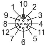 | 1 | OUT_CMN | Common switching output |
| 2 | OUTPUT 1 | Switching output 1 | |
| 3 | INPUT 3 | Switching input 3 | |
| 4 | INP_CMN | Common switching input | |
| 5 | INPUT 1 | Switching input 1 | |
| 6 | GND_extern | External mass | |
| 7 | +UB_extern | External operating voltage | |
| 8 | OUTPUT 4 | Switching output 4 | |
| 9 | OUTPUT 3 | Switching output 3 | |
| 10 | OUTPUT 2 | Switching output 2 | |
| 11 | INPUT 2 | Switching input 2 | |
| 12 | INPUT 4 | Switching input 4 |
7.4.1 Digital inputs
The inputs are electrically isolated from the operating voltage of the device and have a common pole (switching output CMN).
If the electrical isolation is not needed, the operating voltage can also be obtained directly from the device.

Fig. 3: Circuitry of the inputs electrically isolated

Fig. 4: Circuitry of the inputs not electrically isolated
7.4.2 Digital outputs
The outputs are electrically isolated from the operating voltage of the device and have a common pole (switching output CMN).
If the electrical isolation is not needed, the operating voltage can also be obtained directly from the device.

Fig. 5: Circuitry of the outputs electrically isolated
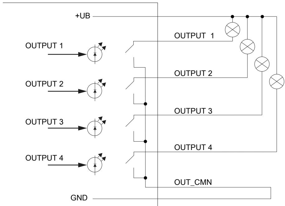
Fig. 6: Circuitry of the outputs not electrically isolated
The inputs and outputs are designed for max. 30 V DC. For further information see the data sheets.
▶ Load the digital inputs and outputs with max. 0.5 A.
▶ Load the used digital inputs and outputs with max. 1.5 A in total.
▶ If the auxiliary voltage of the GPIO connection of the device is used, load the used digital inputs and outputs with max. 1.1 A in total.
▶ For operation of the outputs with an external voltage source, only use LPS (Limited Power Source) or NEC class 2 power supplies.
7.5 Antenna connection
Up to 4 RFID antennas can be connected via the antenna connections. The antenna connections are designed as reverse TNC.
The unit is designed for a maximum antenna gain of 13 dBi and for operation with the following antennas:
- external linear patch antenna (13 dBi, impedance 50 Ohm)
- external antenna with circular polarisation (8 dBi, impedance 50 Ohm)
Only use an antenna if
- the antenna is listed,
- the antenna gain is less than 13 dBi.
Unsuitable connectors decrease the power of the device.
▶ For connection of antennas, only use approved connectors.
▷ Matching connectors at www.ifm.com
8 Operating and display elements

Fig. 7: Display elements on the front of the device
1 Operating status (LED PWR)
3 Freely programmable (LED 1 / 2 / 3 / 4)
2 Without function
8.1 LED PWR
The device displays the operating state via a 2-colour LED.
| Operating status | LED colour | LED state |
| device booting | yellow | ON (permanently) |
| green | OFF | |
| Normal operation | yellow | ON (pulse) |
| green | ON (permanently) | |
| Error during booting | yellow | ON (permanently) |
| green | ON (pulse) |
8.2 LEDs 1 / 2 / 3 / 4
The LEDs 1 / 2 / 3 / 4 can be lit in the colours RGB and are freely programmable.
8.3 Audio signalling device
The device signals the operating state via an audio signalling device. The audio signalling device is freely programmable.
| Sound | Operating status |
| 1x short sound | Device has booted successfully |
| 2x long sound | Device signals an error |
9 Maintenance, repair and disposal
The unit is maintenance-free.
▶ Contact ifm in case of malfunction.
▶ Do not open the housing as the unit does not contain any components which can be maintained by the user. The unit must only be repaired by the manufacturer.
▶ Clean the device using a dry cloth.
▶ Dispose of the unit in accordance with the national environmental regulations.
10 Approvals/standards
10.1 CE labelling
The device complies with the requirements to CE.
Brand name: ifm electronic DTE830 RFID UHF reader for Europe
The device is designed for operation in accordance with EN 302208. When operating the device with connected antennas, observe the human exposure regulations to EN 50364. Ensure a minimum distance of 23 cm between antenna and people. During operation, cardiac pacemakers may be impaired. In case of doubt, persons concerned should consult the manufacturer of the pacemaker or the attending doctor.
The output power of the device can be reduced depending on the antenna cable length and the antenna gain.
10.2 FCC labelling
The device complies with the requirements to FCC Part 15.
Brand name: ifm electronic DTE930 RFID UHF reader for US (FCC)
The device is designed for operation in accordance with FCC Part 15.

▷ This device complies with part 15 of the FCC Rules. Operation is subject to the following two conditions:
▶ This device may not cause harmful interference.
▶ This device must accept any interference received including interference that may cause undesired operation.
The device complies with the FCC limits for radiation exposure in a non-controlled environment: Ensure a minimum distance of 23 cm between antenna and people.
To comply with FCC Part 15 regulations in the United States, the system must be properly installed. The operator and the installer have to ensure that only certified systems are applied in the United States.
10.3 ISED Canada Regulatory Information
The device complies with ISED RSS standards (Radio Standards Specifications) for licence-exempt radio apparatus.
Brand name: ifm electronic DTE930 RFID UHF reader for Canada
Operation is subject to the following two conditions:
(1) the device may not cause interference and
(2) the device must accept any interference received including interference that may cause undesired operation.
Under ISED regulations, this radio transmitter may only operate using an antenna of a type and maximum (or lesser) gain approved for the transmitter by ISED.
▶ To reduce potential radio interference to other users, choose the antenna type and its gain such that the equivalent isotopically radiated power (EIRP) is not more than that necessary for successful communication.
This radio transmitter has been approved by ISED to operate with the antenna types listed as accessories, with the maximum permissible gain and required antenna impedance for each antenna type indicated.
10.3.1 ISED RF Radiation Exposure Statement
This equipment complies with ISED RSS-102 radiation exposure limits set forth for an uncontrolled environment.
Brand name: ifm electronic DTE930 RFID UHF reader for Canada
Make sure this equipment is installed and operated with a minimum distance of 34 centimetres between the radiator and your body.
10.4 Singapore
Complies with
IDA Standards
DB 103032

▷ The Singapore approval is only valid for the RFID reader DTE930.
The “Equipment Registration” is available on our website at: documentation.ifm.com
10.5 MCMC labelling
The device complies with the requirements of MCMC (Malaysian Communications and Multimedia Commission).
Brand name: ifm electronic DTE930 RFID UHF reader for Malaysia (MCMC)
The device is designed for operation according to MCMC MTSFB TC T007, the technical code and specifications for short range devices (SRD).
The frequency range must be set by default to Malaysia.
Incorrect configuration of the device leading to operation outside the frequency range may lead to penalties, including withdrawal of the certificate of conformity.
- 1 PRELIMINARY NOTE
- 1.1 SYMBOLS USED
- 1.2 WARNINGS USED
- 1.3 LEGAL AND COPYRIGHT INFORMATION
- 1.4 OPEN SOURCE INFORMATION
- 2 SAFETY INSTRUCTIONS
- 2.1 CYBERSECURITY
- 3 INTENDED USE
- 4 ITEMS SUPPLIED
- 5 FUNCTION
- 6 INSTALLATION
- 6.1 INSTALL DEVICE
- 6.2 ELIMINATE RADIO DISTURBANCE
- 7 ELECTRICAL CONNECTION
- 7.1 WIRING
- 7.2 POWER SUPPLY
- 7.3 ETHERNET CONNECTION
- 7.4 DIGITAL INPUTS AND OUTPUTS
- 7.4.1 DIGITAL INPUTS
- 7.4.2 DIGITAL OUTPUTS
- 7.5 ANTENNA CONNECTION
- 8 OPERATING AND DISPLAY ELEMENTS
- 8.1 LED PWR
- 8.2 LEDS 1 / 2 / 3 / 4
- 8.3 AUDIO SIGNALLING DEVICE
- 9 MAINTENANCE, REPAIR AND DISPOSAL
- 10 APPROVALS/STANDARDS
- 10.1 CE LABELLING
- 10.2 FCC LABELLING
- 10.3 ISED CANADA REGULATORY INFORMATION
- 10.3.1 ISED RF RADIATION EXPOSURE STATEMENT
- 10.4 SINGAPORE
- 10.5 MCMC LABELLING
Brand : IFM
Model : DTE930
Category : Barcode scanner