HT1E606 - Multimeter Högert - Free user manual and instructions
Find the device manual for free HT1E606 Högert in PDF.

| Product type | Digital multimeter |
| Brand | Högert |
| Model | HT1E606 |
| Power supply | 9V 6F22 battery |
| Dimensions (approx.) | 150 x 75 x 35 mm |
| Weight (approx.) | 300 g (with battery) |
| Display | LCD 4000 counts, backlit |
| Max voltage (DC/AC) | 2000 V |
| Max current (DC/AC) | 200 mA (with fuse) |
| Max resistance | 40 MΩ (estimate) |
| Max capacitance | 100 µF (estimate) |
| Max frequency | 10 MHz (estimate) |
| Temperature | -20°C to 1000°C (with thermocouple) |
| Special functions | NCV detection, transistor hFE test, diode test, continuity buzzer |
| Protection | Fuse, auto power off, low battery indication |
| Safety | Compliant with IEC61010-400V CATII, pollution degree 2 |
| Maintenance | Clean with soft cloth, replace battery and fuse if necessary |
| Spare parts | 9V battery, replacement fuse (identical) |
| Warranty | 2 years (subject to manufacturer's conditions) |
Frequently Asked Questions - HT1E606 Högert
User questions about HT1E606 Högert
0 question about this device. Answer the ones you know or ask your own.
Ask a new question about this device
Download the instructions for your Multimeter in PDF format for free! Find your manual HT1E606 - Högert and take your electronic device back in hand. On this page are published all the documents necessary for the use of your device. HT1E606 by Högert.
USER MANUAL HT1E606 Högert
Thank you for purchasing our product. Our product, manufactured to a high standard, will provide years of trouble-free operation if used in accordance with the instructions and properly maintained.
TABLE OF CONTENTS
- General information
- General safety conditions
- Description and functions
- Measurements
4.1. Inductive measurement NCV
4.2. Measurement of voltage U DC/AC
4.3. Measurement of voltage I DC/AC
4.4.Resistancemeasurement
4.5.Capacitytest
4.6.Frequencytest
4.7.Temperaturetest
4.8.Continuitytest
4.9. HFE transistor test
- Specifications
5.1.Technical Specification
5.2.Electricalspecification - Maintenance
6.1. Battery replacement
6-2. Fuse replacement
6-3.Maintenance


Environmental protection

Symbol indicating separate collection of electrical and electronic equipment waste. Used electrical appliances are secondary raw materials - they must not be disposed of in household waste, as they contain substances hazardous to human health and the environment! Please actively help us to manage natural resources and protect the environment by handing over used equipment to the waste electrical equipment storage point. To reduce the amount of waste disposed of, it
is necessary to reuse, recycle or recover it in another form.
1. GENERAL INFORMATION
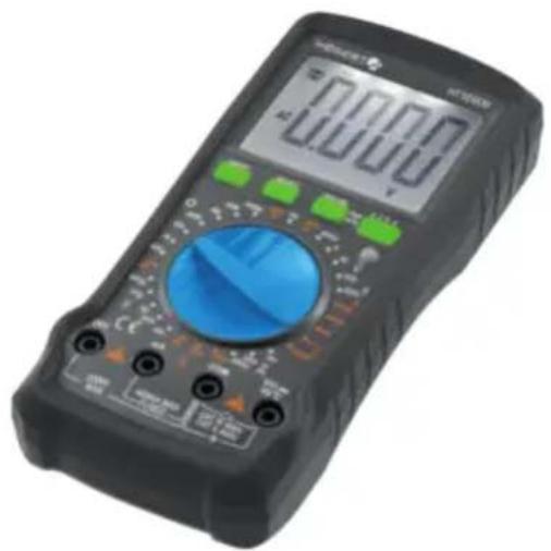
The device is intended for use both in private households and for commercial purposes. The HT1E606 Digital Multimeter is an innovative, powerful, reliable, battery-powered, full-featured instrument with AC and DC voltage measurement up to 2000V, contactless NCV and temperature measurement, with a large LCD screen showing 4000 characters.
The meter is equipped with an overload protection circuit that can be used to measure DC and AC voltage, AC and DC current, resistance, capacity, frequency, live wires, battery voltage, non-contact NCV detection, diode and circuit continuity. Any other use is not intended and may lead to property damage or even personal injury. Use the device only in accordance with this manual. The manufacturer does not assume any liability for damage caused by improper use. The device is not a measuring device within the meaning of the .Measurement Law".
2. GENERAL SAFETY CONDITIONS
It is within the scope of the owner and user's responsibility to read, understand and follow these rules:

IMPORTANT: Please read this manual carefully. Please pay special attention to the requirements of safe use, warnings and notices. Use the product correctly and carefully for the purposes for which it is intended. Failure to do so may result in damage and/or harm to health and will void the warranty. Please keep this manual in a safe place for further use. When
passing the device on to another person, also give them the manual.
- Please use the device only for the purpose intended for the device.
- Please keep the device away from heat, direct sunlight, moisture (under no circumstances immerse in liquid substances) and sharp edges. Do not operate the device with wet hands.
- Do not leave the device running unattended. Always switch off the unit before leaving the room.
- Check regularly that the device is not damaged. If damage is detected, stop using the device.
- For the safety of children, please do not leave any freely accessible parts of the packaging (plastic bags, cartons, polystyrene, etc.).
WARNING
Don't let the kids play with the foil. Danger of suffocation!
This device is not intended for use by persons with reduced physical, sensory or mental capabilities or lack of experience and/or skills, unless such persons are accompanied and supervised by persons responsible for their safety or have received precise instruc
tions for the device usage and understand the risks involved. Children may only use this device if they are over 8 years old and under the supervision of a person responsible for their safety or if they have received instructions for use of this device and understand the risks involved. Children cannot play with this device.
SAFETY INFORMATION
The HT1E606 digital multimeter is designed according to the IEC61010-1 400 V (CATIII) directive and contamination level 2. To ensure proper and safe use of the meter, read the manual carefully.
- Do not measure a voltage that exceeds the measuring range specified for this meter.
- Despite the internal protective circuit for the resistance measurement field, do NOT add 100 V or more to the input terminal in the resistance measurement field.
- Check that the probes are connected correctly.
- Avoid using the meter in direct sunlight or extremely high temperatures, if possible.
- Avoid the risk of electric shock when measuring voltages exceeding 30 V AC or 60 V DC.
- Switch off the power supply and disconnect it from the circuit before the current measurement.
- Pay attention to polarity when replacing batteries.
ELECTRICAL SYMBOLS:
| High voltage can occur. . Ground | ||
| Alternating Current AC | Important safety information. | |
| Direct Current DC Double insulation | ||
| Direct or alternating current DC/AC | Fuse | |
3.DESCRIPTION AND FUNCTIONS
- ON/OFF - turn the device on/off;
- SELECT - Press the "SELECT" button to switch the function and unit of measurement;
- HOLD / BL - HOLD to stop the reading during the measurement, you can press the .HOLD" button, and then the measurement reading will be locked on the display. Press the .HOLD" button again, the read pause status will be released. Hold this button down for about 2 seconds to turn on the backlight (BL - Back Light), which turns off automatically after 15 seconds; you can turn it off by pressing the button again.
4.MEASUREMENTS
4.1. Inductive measurement NCV
- Turn the function knob to the NCV position.
- Then grasp the instrument and bring the front of the instrument closer to the test piece.
- The built-in buzzer will beep when the internal sensor detects AC nearby. The stronger the current, the faster the buzzing and the central LED will flash.
4.2.Voltage measurement U DC/AC (>1V)
- The device will display the value when measuring current above 1V;
- Turn the function knob to the desired position. When measuring direct voltage, select the appropriate range marked V, and when measuring alternating voltage V.
- Insert the end of the red test lead into the terminal marked , insert the end of the black test lead into the .COM" terminal;
- Put the ends of the test leads to the measured elements.
- Read the measurements on the display.
4.3. Current measurement I DC/AC
- Insert the end of the red test lead into the terminal marked .mA", insert the end of the black test lead into the clack ..COM" terminal:
- Turn the function knob to the desired position. When measuring direct voltage, select the appropriate range marked V, and when measuring alternating voltage V.
- Put the ends of the test leads to the measured element.
- Read the intensity value on the display.
4.4. Resistance measurement
To avoid damage to the meter or the device under test, disconnect the power supply to the circuit under test and completely discharge all high voltage capacitors before measuring the resistance.
- Set the function switch to the appropriate field within the range marked . At first the meter displays , indicating that the input is in an open circuit, i.e. no resistance is connected.
- Connect the black probe to the .COM" input socket and the red probe to the .VΩ" input socket.
- Use the probe tips to measure the resistance of the circuit being tested.
- Read the measured resistance value on the display.
4.5. Capacity measurement F
- Insert the end of the red test lead into the terminal marked .VΩ", insert the end of the black test lead into the .COM" terminal;
- Turn the function knob to the desired position within the range marked F;
- Put the ends of the test leads to the measured element,
- Read the capacity value on the display.
4.6. Hz frequency measurement
- Insert the end of the red test lead into the terminal marked V Hz^ , insert the end of the black test lead into the .COM" terminal;
- Turn the function knob to the position marked Hz;
- Put the ends of the test leads to the measured element,
- Read the frequency value on the display.
4.7. TEMP temperature measurement
- Additional leads for temperature measurement are included with the device. Insert the end of the red test lead into the terminal marked V Hz^ insert the end of the black test lead into the COM" terminal;
- Turn the function knob to the position marked TEMP;
- Put the ends of the test leads to the measured element,
- Read the temperature value on the display.
4.8. Continuity test
- Insert the end of the red test lead into the terminal marked , insert the end of the black test lead into the .COM" terminal;
- Set the function switch to ;
- Put the ends of the test leads to the measured elements, the measurement result will be shown on the display;
- The built-in buzzer will sound if the resistance between the probes is less than 30 + / - 10
4.9. NPN, PNP Transistor test
- Set the function switch to „hFE";
- Make sure the transistor is of NPN or PNP type;
- Place the transistor properly in the E.B.C port;
- Read the result on the display.
5.SPECIFICATION
5.1. Technical Specification
| Specification of external conditions | ||
| Use | Temperature 0~40°C | |
| Humidity < 75% | ||
| Storage | Temperature -10~50°C | |
| Humidity < 75% | ||
| Technical Specification | |||
| Display 4000 characters | Data Hold V | ||
| Material ABS Backlit display V | |||
| Sampling frequency 3/s Contactless measurement √ | |||
| Low battery indication: √ Auto off √ | |||
5.2. ELECTRICAL SPECIFICATION
1. CONTINUITY AND INDUCTIVE TEST
| Continuity test √ | |
| NCV √ |
2. U DC/AC voltage
| Function Range | Resolution Accuracy Max. | ||
| UDC voltage (V) | 400mV 100uV | ±(0.5%+5d) | 2000V |
| 4V 1mV | |||
| 40V | 10mV | ||
| 400V | 100mV | ||
| 2000V | 1V | (2.0%+5d) | |
| UAC voltage (V) | 400mV 100uV | ±(0,5%+5d) | 2000V |
| 4V 1mV | |||
| 40V | 10mV | ||
| 400V | 100mV | ||
| 2000V | 1V | (2.0%+5d) |
3. Voltage I DC/AC
| Function Range | Resolution Accuracy Max. | |||
| IDC intensity [A] | 4mA | 1uA | ±[1.0%+3d] ±[1.0%+3d] | 400mA |
| 40mA | 10uA | |||
| 400mA | 100uA | ±[1.0%+3d] | ||
| IUC voltage [A] | 4mA | 1uA | ±[2.0%+3d] ±[2.0%+3d] | 400mA |
| 40mA | 10uA | |||
| 400mA | 100uA ±{2.0} | %+5d | ||
4. Resistance R
| Function Range | Resolution Accuracy Max. | |||
| Resistance | 400Ω | 0.1Ω | ±(1.0%+5d) | 400MΩ |
| 4KΩ 1Ω | ||||
| 40KΩ | 10Ω | ±(1.0%+5d) | ||
| 400KΩ | 100Ω | |||
| 4MΩ | 1KΩ | |||
| 40MΩ | 10KΩ | ±(1.2%+8d) | ||
| 400MΩ | 100KΩ | ±(4%+10d) | ||
5. Capacity F
| Function Range | Resolution Accuracy Max. | ||
| Capacity | 40nF 10pF | ±(4.0%+5d) 400uF | |
| 400nF 100pF | |||
| 4uF 1nF | |||
| 40uF 10nF | |||
| 400uF 100nF |
6. Frequency Hz
| Function Range | Resolution Accuracy Max. | ||
| Frequency | 4kHz 1Hz | ±(1.5%+8d) | |
| 40kH 10Hz | |||
| 400kH 100Hz | |||
| 4MHz 1kHz | ±(1.5%+40d) |
7. Temperature
| Function Range | Resolution Accuracy Max. | |||
| Temperature | -40°C~400°C 1°C | ±(1%+8d) ±(1.5%+15d) | 1000°C | |
| -400°C ~1000°C 1°C | ||||
6. MAINTENANCE
6-1. Battery replacement
If the symbol appears on the LCD while using the meter, replace the battery to prevent incorrect reading of measurements.
- Disconnect the test wires. Turn off the power.
- Use a screwdriver to open the battery cover on the back, and then remove the battery.
- Place the charged 9V 6F22 battery and replace the cover.
6.2. Fuse replacement
- First remove the test lines and turn off the meter.
- Use a screwdriver to open the rear cover, then remove the faulty fuse.
- Insert a similar fuse, move the rear cover and fix it with screws.
6.3. Maintenance
If necessary, use a soft cloth to wipe the surface of the meter. Do not use organic solvents or abrasive materials that may corrode or dissolve the case.
DE
BENUTZERHANDBUCH UNIVERSELL DIGITAL MESSGERAT HT1E606
1.ALLGEMEINEINFORMATIONEN
4.3.ИЗмeperнешка I DC/AC
- BCTaBbTe HakoHeuHc KpaCHOro TectOBoro npoBOda B KJIeMMy C MapKnupOBko "mA, BCTaBbTe HakoHeuHc YepHOrO TectOBoro npoBOda B KJIeMMy C MapKnupOBko COM cepHOrO cBeTa.
- YctaHOBIne yHKUHOHaJIbHyIO pyuKy B HxKHOE NOLOXKeHne. Pn n3MepeHn NocToHHoro TOKa BbI6epTe COOTBeTCTByIOuN nnana3OH, 06O3HaueHHbI A, a npn n3MepeHn nepeMeHHoro TOKa BbI6epTe A.
3.YCTaHOBNTe KOHcblNCbIITaTeNbHbIX npoBOOBA Ha n3MepreMbte 3JeMeHTbl.
4.ПpoTuTne pe3yIbTaTbI n3MepeHnHa nIcPiIe
4.6.N3MepeHHe yactoTbI T
- BCTaBbTe HakoHeuHrk KpaChoro n3MepntelbHoro npoBa D K BXoHomy rHe3ny..BΩT, BcTaBbTe HakoHeuHrk YepHoro n3MepeNTelbHoro Ka6eJr B..COM";
2.YctaHOBNTe yHKUHOHaJIbHyU pyKy B NOJIOKeHne B npeJeIax OTMeueHHOrO dnaNa3oHa T;
3.YctaHOBNTe KOHcblIcNbItaTeNbHbIX npoBOOB Ha n3MepReMbte 3JeMeHTbl;
4.ПpoTuTnepe3yIbTaTbIи3MpeHnHaДиCnnee.
4.7.Измерени TemпераТурbl TEMP
- MylbTtmeTp cna6xeh ndoJIHnTeIbHbIMn Ka6eJAMn, npEHa3HaueHHbIMn IJIg N3MepeHnra TeMnpaTypb.I BcTaBbTe HaKoHeuHnKpachoro N3MePHTeIbHO rpoBaDa B K BXoHOMy rHe3dy .B0rC", BcTaBbTe HAcOHeuHk YepHOrO N3MePHTeIbHO rO Ka6eJBA"COM";
2.YctaHOBITEyHKUHOHaJIbHyUpyKByNoIooKeHneO6o3HaueHoeTEMP;
3.YCTaHOBNTe KOHcblNCbIaTeNbHbIX npoBOOHa Hn3MepeReMbte 3JeMeHTbl;
4.ПpoTuTnepe3yIbTaTbIи3MepeHnHaДиCnPee.
4.8.Tec HnpepbBbHocTn
- BCTaBbTe HaKoHeuHnK KpaChHOrO n3MepnteJbHOrO npOBoJa B K BXoHOMy rHe3Ny "BΩ", BCTaBbTe HaKoHeuHnK YepHOrO n3MepnteJbHOrO ka6eJIa B..COM";
2.YctaHOBnTeyHKUHOHaJIbHyOpyuKyBNoIOXKeHne;
3.YctaHOBtE KOHcbl NcblTaTeNbHbIX npoBOOb Ha n3MepReMbte 3JeMeHTbI,pe3yJbTaTb6dyT yKa3aHbHa nnCnnee; - BCTpoHHbIy 3yMMep nOaCT 3ByKOBoCnHaN, ecN cOnpOTnBHeHne MeKdy DaTnKaMn MeHbSe, yem 30 + / - 10
4.9.TecTtpaH3nctopoB NPN, PNP
1.YctahOBHTe yHKUHOHaJIbHyO pyky B noJIOxKeHHe...hFE";
2.Y6eDntecb,yToTpaH3nCTOp UMeet Tyn NPN uN PNP;
3.ПометichteТранзов БпOT E.B.C.coTBeTCTBeHHO;
4.ПpoHTIpe3yJIbTaTbIи3MpeHnHaДиCnnee.
5.CTELUΦNKAUN
5.1.CneunikauaTexnueckaa
1.1.TecTcIIOCTHOCTN INHdyKUHN
| Тек удиoc'thoctу V | |
| NCV V |
2. HanpxkeHne U DC/AC
| Фунreichа | Диапазон | Раширеения | Точность | Марс. |
| Нар就近еги UDC (B) | 400mV | 100uV | ±(0.5%+5d) | 2000V |
| 4V | 1mV | |||
| 40V | 10mV | ±(0.8%+5d) | ||
| 400V | 100mV | |||
| 2000V 1V | (2.0%+5d) | |||
| Нар就近еги UAC (B) | 400mV | 100uV | ±(0,5%+5d) | 2000V |
| 4V | 1mV | |||
| 40V | 10mV | ±(0,8%+5d) | ||
| 400V | 100mV | |||
| 2000V 1V | (2.0%+5d) |
3. TokIDC/AC
| Функция | Диапазон | Раизessesе | Точность | Марс. |
| Nateżenie IDC (A) | 4mA 1uA | ±(1.0%+3d) ±(1.0%+3d) | 400mA | |
| 40mA | 10uA | |||
| 400mA | 100uA | ±(1.0%+3d) | ||
| Napiȩcie IUC (A) | 4mA 1uA | ±(2.0%+3d) ±(2.0%+3d) | 400mA | |
| 40mA | 10uA | |||
| 400mA | 100uA | ±(2.0%+5d) |
4. ConpoTnBLeHne R
| Функция Дniaц | аzoи РазPEC themselves | Tochocь Мaks | ||
| Соротавлике | 400Ω 0.1Ω | ±(1.0%+5d) | KΩ 1000MΩ | |
| 4КΩ 1Ω | ||||
| 40KΩ 10Ω | ±(1.0%+5d)400 | |||
| 4MΩ 1KΩ | ||||
| 40MΩ 10KΩ | ±(1.2%+8d) | |||
| 400MΩ 100KΩ | ±(4%+10d) |
5.EMKOCbF
5.1. Specification technique
| Fonction Étendue Résolution Précision Max | ||||
| Intensité IDC (A) | 4mA 1uA | ± [1.0%+3d] ± [1.0%+3d] | 400mA40mA 10uA | |
| 400mA 100uA ± [1.0%+3d] | ||||
| Tension IUC (A) | 4mA 1uA | ±(2.0%+3d) ±(2.0%+3d) | 400mA40mA 10uA | |
| 400mA 100uA ±[2.0%+5d] | ||||
- Résistance R
| Fonction Étendue Résolution Précision Max | ||||
| Résistance | 400Ω | 0.1Ω | ±(1.0%+5d) | 400MΩ |
| 4KΩ 1Ω | ||||
| 40KΩ 10Ω | ±(1.0%+5d) | |||
| 400KΩ 100Ω | ||||
| 4MΩ | 1KΩ | |||
| 40MΩ | 10KΩ | ±(1.2%+8d) | ||
| 400MΩ | 100KΩ | ±(4%+10d) | ||
5. Capacité F
| Fonction Étendue Résolution Précision Max | |||
| Capacité | 40nF 10pF | ±(4.0%+5d) 400uF | |
| 400nF 100pF | |||
| 4uF 1nF | |||
| 40uF 10nF | |||
| 400uF 100nF | |||
6. Fréquence Hz
| Fonction Étendue Résolution Précision Max | |||
| Fréquence | 4kHz 1Hz | ±(1.5%+8d) | |
| 40kH 10Hz | |||
| 400kH 100Hz | |||
| 4MHz 1kHz ±[1.5%+40d] | |||
7.Temperature
| Fonction Étendue Résolution Precision | Max | |||
| Température | -40°C~400°C 1°C | ±(1%+8d) ±(1.5%+15d) | 1000°C | |
| -400°C ~ 1000°C 1°C | ||||