HV150 A - Basket Thermex - Free user manual and instructions
Find the device manual for free HV150 A Thermex in PDF.

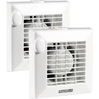
| Product type | Range hood (air extractor) |
| Brand | Thermex |
| Model | HV150 A |
| Installation | Window (glass 3-25 mm) or wall (25-300 mm) |
| Power supply | 220-240 V, 50 Hz (see rating plate) |
| Electrical class | Class II (double insulation, no earthing required) |
| Motor protection | Built-in thermal fuse |
| Operating modes | 3 modes: stop shutter closed, stop shutter open (natural ventilation), run forced extraction |
| Control | CR-300 unit (accessory) to control modes |
| Control capacity | One CR-150 can control up to 5 HV-150A (by modifying the bridge between 5-1 and 5-2) |
| Max ambient temperature | 45 °C |
| Usage | Indoor only, avoid explosive or corrosive environments |
| Maintenance | Clean with a soft cloth dampened with water; periodically check the condition of the propeller |
| Safety | Disconnect the appliance before any intervention; do not clean with a pressurized water jet |
| Warranty | Void if handled by a person not approved by S&P |
| Minimum user age | 8 years and older (with supervision if reduced capabilities) |
| Louver (shutter) | Integrated louver mechanism, check proper operation during installation |
| Supplied accessories | Threaded rods and sleeves for wall installation |
| General information | Instructions available in several languages; S&P reserves the right to modify instructions |
Frequently Asked Questions - HV150 A Thermex
User questions about HV150 A Thermex
0 question about this device. Answer the ones you know or ask your own.
Ask a new question about this device
Download the instructions for your Basket in PDF format for free! Find your manual HV150 A - Thermex and take your electronic device back in hand. On this page are published all the documents necessary for the use of your device. HV150 A by Thermex.
USER MANUAL HV150 A Thermex
natural_image
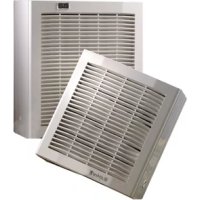
White industrial air vent with slatted ventilation grille and 'Stylvent' logo on side (no text-heavy elements)Fig. A
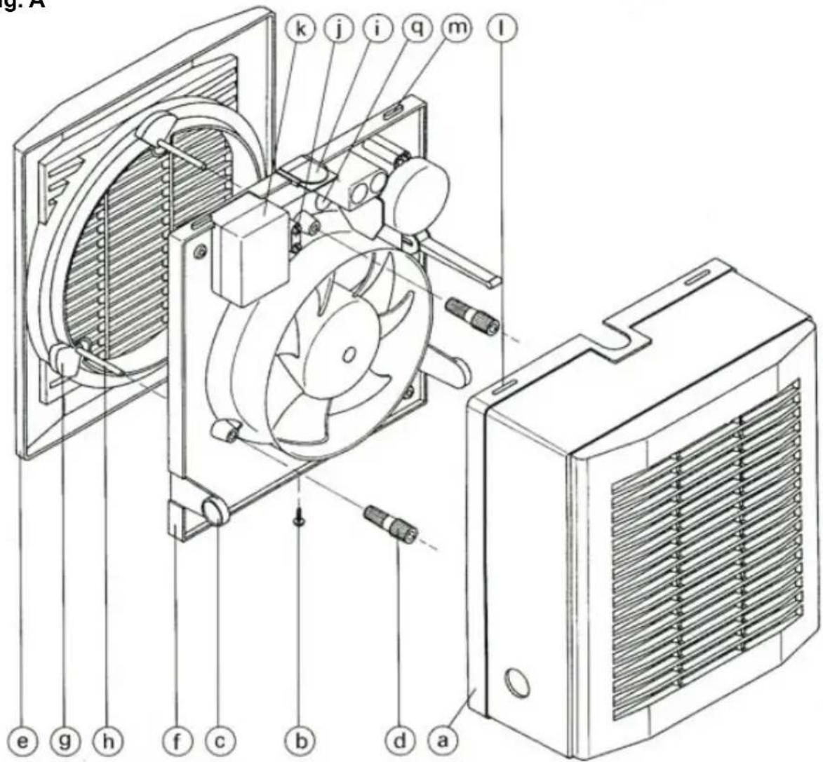
Fig. B
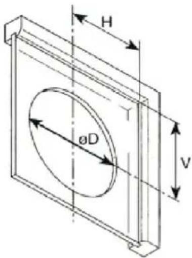
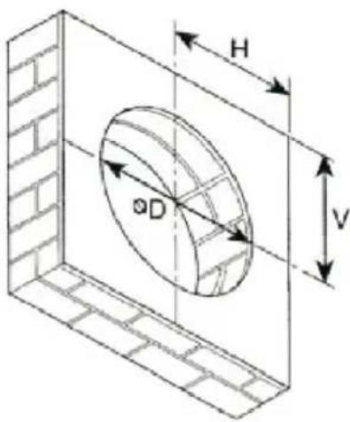
| (mm) | HV-150 |
| ∅D Mini | 187 |
| ∅D Maxi | 190 |
| H Mini | 150 |
| V Mini | 160 |
natural_image
Technical line drawing of a heat exchanger or cooling unit (no text or symbols)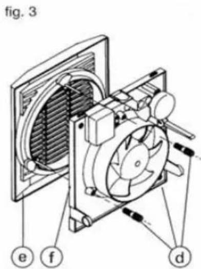
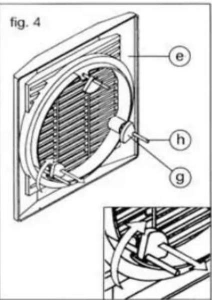
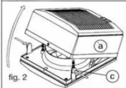
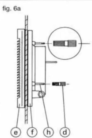
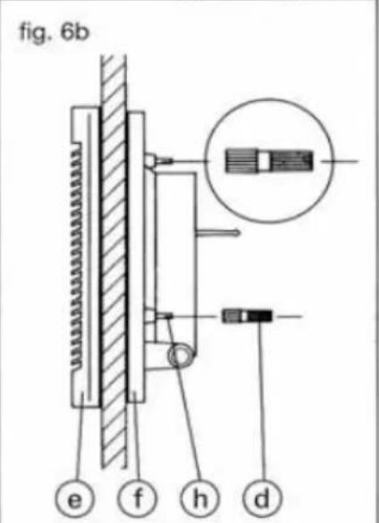
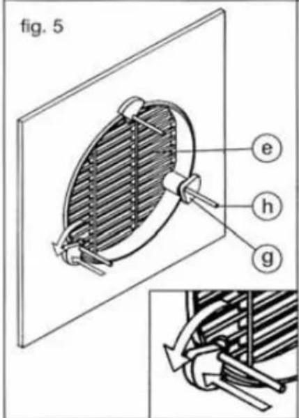
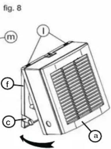
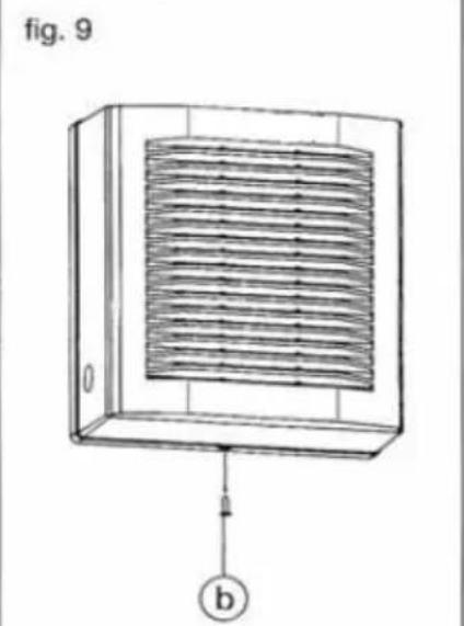
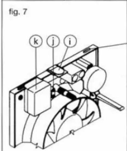
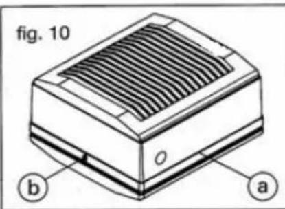
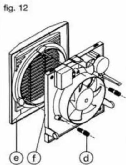
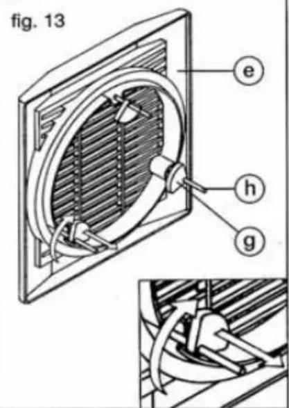
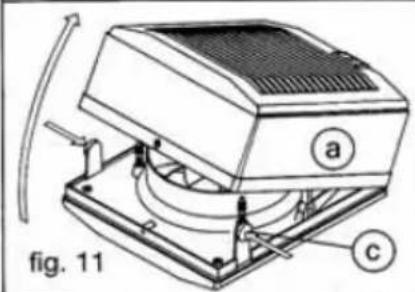
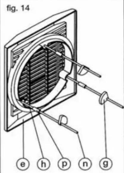
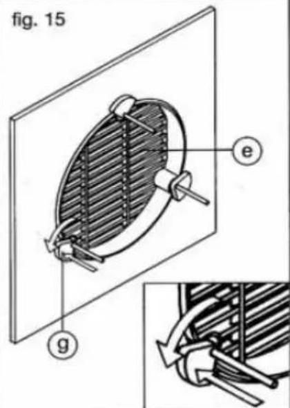
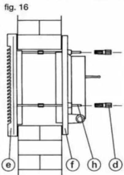
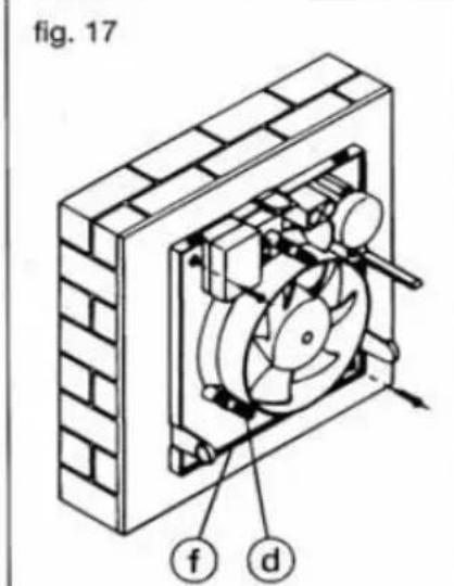
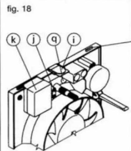
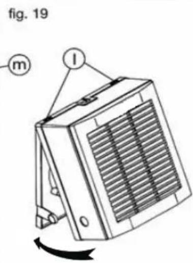
Fig. C (HV-150 M / AE)
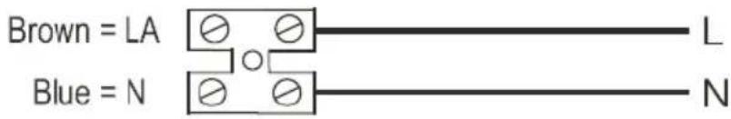
Fig. D (HV-150 A)
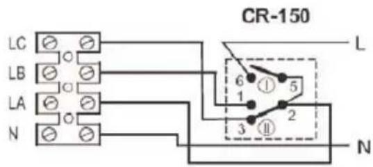
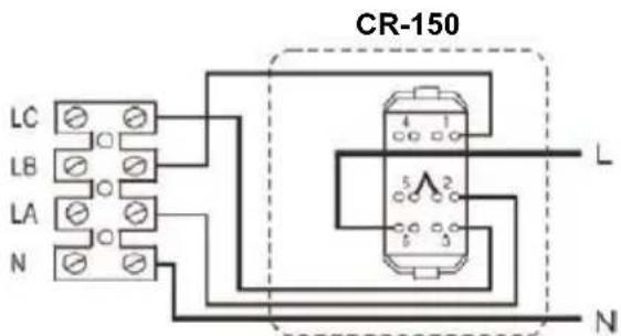
CAUTION: The connection bridge must be changed from 5-1 to 5-2.
natural_image
White electrical switch device labeled CR-150, featuring two side panels with a star symbol on the right panel (no readable text or symbols beyond label)Please read these instructions carefully before using the product in order to avoid damage or any dangerous situations arising. Any use of the product other than that indicated in this manual may cause fire, electrical danger, or injury and will make the warranty null and void.
The warranty does not cover any defect, deterioration, loss, injury, or damage that is due to incorrect use of the product. All legal rights in this regard are guaranteed. No warranty condition can exclude or change the warranty conditions regulated by State laws that may not be excluded or modified for any reason.
- All appliances are supplied in perfect condition and operation. However if found to be defective the unit should be returned to the supplier in accordance with the terms of the S&P guarantee.
Should any defects or damage be found, do not install or attempt to repair the equipment, but contact the dealer.
Do not leave the packaging within reach of children and dispose of the parts in compliance with current provisions.
FITTING AND WIRING INSTRUCTIONS
Important recommendations
Before installing the device or performing any maintenance, make sure all the safety instructions listed below, will be fully met:
- The installation must be in accordance with the electrical standards and regulations in force in your country and by qualified personnel.
- The HV range is designed to be installed in windows and walls.
- To prevent a return into the gas room, from the evacuation tube of gas appliance or other gas appliances that burn fuel, it must prevent and ensure that the air inlets are sufficient and not obstructed.
- Do not use these products for explosive or corrosive environments.
- Ensure that the voltage and frequency of the mains are compatible with the values indicated in the nameplate of the device.
- The electrical installation must include a double pole switch that has an opening distance between contacts of at least 3mm.
- The HV series fans are class II (double electrical insulation), so there is no need to connect to an earth connection.
- This product is designed for use in places where the ambient temperature does not exceed +45°C.
- This appliance can be used by children aged from 8 years and above and persons with reduced physical, sensory or mental capabilities or lack of experience and knowledge if they have been given supervision or instruction concerning use of the appliance in a safe way and understand the hazards involved.
- Children shall not play with the appliance.
- Cleaning and user maintenance shall not be made by children without supervision.
- The installer must provide access to the fan to facilitate future maintenance and ensure it is properly fixed and installed.
- The motor of HV-150N models incorporate a thermal fuse.
- Ensure that the arm of the shutter is in the same slot when the external grille is mounted. Check the correct operation of the shutter mechanism.
- It is recommended that you check the condition and operation of the appliance after unpacking it; any factory defect is covered by the S&P guarantee.
Mounting on Glass windows (Glass thickness between 3-25 mm)
You can identify all the components of the device in figure A, and the measures required for the correct installation of the device in figure B.
Cut a hole following the dimensions indicated on figure B. It is recommended that this should be a minimum of 1,5 meters from ground level.
- Dismantle the HV-fan in accordance with the following instructions:
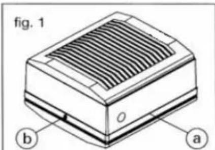
Fig. 1.- Loosen the retaining screw (b) fixing the internal front cover (a).
Fig. 2.- Remove the internal front cover (a) by pressing the knobs (c).
Fig. 3.- Unscrew the 3 bolts (d) fixing the external grille (e) and separate from the support plate (f).
- Install the HV on the glass as indicated below:
Fig. 4.- Pull the external grille (e) towards you and turn the rubber mounting (g) on the screws (h), towards the inner side of the grille.
Fig. 5.- From the outside, place the external grille (e) over the hole in the glass. From the inside, turn and push the rubber mountings (g) until they are located against the glass keeping the external grille (e) in its correct position.
Fig. 6.- Mount the support plate (f) to the screws (h) of the external grille (e) and tighten the bolts (d) to suit the thickness of the glass:
- Glass thickness 3 - 14 mm: Fig. 6a
- Panel thickness 14 - 25 mm: Fig. 6b
- Tighten the screws taking care not to flatten the rubber joints between the support plate and the external grille.
Ensure that the glass is not in contact with the plastic frame.
Fig.7.- Make the necessary hole in the gland (i), and feed the electrical cables through the clamp (j) and connect them in the terminal box (k).
Fig. 8.- Mount the internal cover (a) by slotting the rectangular openings (1) on the top of the cover (a) into the receivers (m) of the support plate (f) until the two knobs (c) are correctly positioned.
Fig. 9.- Tighten the locking screw (b)
Wall mounting (wall thickness between 25 - 300mm)
(Ensure that threaded couplers and extended fixing rod (h) are supplied as accessories)
- Cut a hole in the wall where the unit is to be mounted, in accordance with the dimensions indicated in figure B. It is recommended that this should be a minimum of 1.5 meters from ground level.
- Measure the thickness of the wall and cut the threaded rods (n) 5 mm shorter than this thickness.
- Use the appliance to mark on the wall the position of the fixing holes for the support plate (f), drill the fixing holes and insert the wall plugs.
- Dismantle the HV-fan in accordance with the following instructions:
Fig.10.- Loosen the retaining screw (b) fixing the internal front cover (a).
Fig.11.- Remove the internal front cover (a) by pressing the knobs (c).
Fig.12.- Loosen the 3 bolts (d) fixing the internal grille (e) and separate it from the support plate (f).
- Install the HV-fan in the wall as follows:
Fig.13.- Pull the internal grille (e) towards you and take the rubber mountings (g) away from the screws (h).
Fig.14.- Fix the threaded rods (n) to the screws (h) on the external grille (e) with the threaded couplers (p) supplied and put back the rubber mountings (g) on the rods.
Fig.15.- From the outside, place the external grille (e) over the hole in the wall. From the inside, turn and push the rubber mountings (g) until they are located against the wall keeping the external grille (e) in its correct position.
Fig.16.- Mount the support plate (f) to the threaded rods (n) and tighten the bolts (d) to suit the length of the rod sticking out from the support plate (f).
Fig.17.- Fix the support plate (f) to the wall and tighten bolts (d).
Fig.18.- Depending on the position of the incoming electrical cables, make a hole on the gland (i) on the front cover (a) or in the gland (p) on the support plate (f), introduce the electrical cables through the clamp (j) and connect to the terminal box (k).
Fig.19.- Mount the internal cover (a) by slotting the rectangular openings (1) on the top of the cover (a) into the receivers (m) of the support plate (f) until the two knobs (c) are correctly positioned.
Fig. 9.- Tighten the locking screw (b).
Electrical wiring
- Before proceeding to the electrical wiring, make sure it is disconnected from the electrical supply. Also make sure that the impeller rotates freely and there are no obstructions in the inlet or outlet fan.
- Make sure the voltage and frequency of the network coincide with the technical values determined in the technical plate.
- Electrical wiring HV-150 M model: according to scheme figure C.
- Electrical wiring HV150 AE model: according to scheme figure C.
- Electrical wiring HV-150 A model: according to scheme figure D.
(To operate all these functions use the accessory CR-150 of S&P)
Operation mode
• HV-150 M Model
(Manually operated via pull cord)
3 operation modes via pull cord
Mode 1 Fan Off – Shutter closed
Mode 2 Fan Off – Shutter open (natural ventilation).
Mode 3 Fan On- Working as air extract (Mechanical ventilation)
• HV-150 AE Model
2 operation modes:
Mode 1 Fan Off – Shutter closed
Mode 2 Fan On – Working as air extract
• HV-150 A Model
(To operate all these functions use the accessory CR-150 of S&P)
3 operation modes:
Mode 1 Fan Off – Shutter closed
Mode 2 Fan Off – Shutter open (Natural ventilation).
Mode 3 Fan On – Working as air extract (Mechanical ventilation).
OFF: Shutter closed / air extract closed
ON + ≠ : Shutter open / air extract closed (natural ventilation)
ON + ★ : Shutter open / working as air extract (mechanical ventilation)
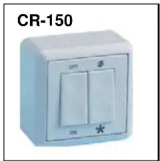
ATTENTION: The CR-150 control of S&P is delivered with a joint between contacts 5-1. This joint has to be moved, so that the joint is positioned between contacts 5-2.
NOTE: One CR-150 of S&P can control up to 5 HV-150A.
Maintenance
- Before handling the fan, make sure it is disconnected from the mains supply
- Clean regularly with a soft cloth moistened with water.
- Periodically check the state of the impeller
- Do not clean with pressure water jet.
Removal from service, disposal and recycling
The CEE norm and our commitment to future generations require us to recycle waste material; please deposit all remaining elements of the packaging into containers for recycling, and take the equipment that has been replaced to the nearest waste centre or your dealer.
Technical assistance
The extensive S&P Official Services Network guarantees competent technical assistance anywhere in Spain.
If any anomalies are observed in the appliance, please contact any of the Technical Services on the list to deal with your problem.
Any handling of the appliance by persons other than S&P Official Services will lead to the guarantee being cancelled.
S&P reserves the right to make any modifications without prior notice.
FRANCAIS
GAMME HV-150 M / AE / A
natural_image
White electrical switch device labeled CR-150, featuring two panels with a star symbol (no readable text or symbols beyond label)Assistance technique
natural_image
White electrical switch with two side panels and a star symbol, labeled CR-150 (no additional text or symbols)GAMMA HV-150 M / AE / A
natural_image
White electrical switch device labeled CR-150, featuring two vertical panels with a star symbol on the side (no additional text or symbols)natural_image
White electrical switch device labeled CR-150, featuring two vertical panels and a star symbol (no readable text or symbols beyond label)(MM25 - 3) ت Erkb on the Wafadz Rajajia (Smaoka Rajaj in MM25)
natural_image
White electrical switch with two side panels and a star symbol, labeled CR-150 (no additional text or symbols)مصراجعغلاقاستخرالهولغلاق:OFF