
APWD15E - Tumble dryer FRIGIDAIRE - Free user manual and instructions
Find the device manual for free APWD15E FRIGIDAIRE in PDF.
| Product type | Clothes dryer |
| Brand | Frigidaire |
| Model | APWD15E |
| Drying capacity | 7.5 kg |
| Height | 85 cm |
| Width | 60 cm |
| Depth | 60 cm |
| Net weight | 45 kg |
| Power supply | 240 V, 30 A |
| Drying programs | Automatic drying, timer, delicate, easy iron |
| Moisture sensors | Yes |
| Anti-crease function | Yes |
| Venting type | Ducted venting |
| Lint filter | Clean after each cycle |
| Child safety | Not specified |
| Auto shut-off | Yes |
| Spare parts available | Yes, through after-sales service |
| Mechanical parts warranty | 1 year |
| Compatible optional pedestal | Yes, 38 cm (15 in) high |
Frequently Asked Questions - APWD15E FRIGIDAIRE
User questions about APWD15E FRIGIDAIRE
0 question about this device. Answer the ones you know or ask your own.
Ask a new question about this device
Download the instructions for your Tumble dryer in PDF format for free! Find your manual APWD15E - FRIGIDAIRE and take your electronic device back in hand. On this page are published all the documents necessary for the use of your device. APWD15E by FRIGIDAIRE.
USER MANUAL APWD15E FRIGIDAIRE
Installation Instructions
15" Pedestal
137147900 A (0904)
KIT COMPONENTS:
1 Pedestal Installation Instructions.
2 Front brackets.A
2 Front bracket spacers.B
2 Rear brackets.C
14 #10 (16 x .500) screws.D
COMPOSANTS DU NÉCESSAIRE:
IMPORTANT Total weight IN closed drawer or combination of IN and ON TOP OF open drawer should not exceed 65 lb. (29.5 kg).
Optional universal wrench available from dealer
Clé universelle
9/16" or 14 mm box wrench
Clé polygonale de
9/16 po ou de 14 mm
Llave de cubo de
9/16 po o 14 mm
AND ET Y
Phillips screwdriver
Tournevis Phillips
Destornillador Phillips
AND ET Y
Carpenter's level
- Failure to disconnect from power source before stacking could result in personal injury or even death.
- Improper installation of dryer venting could result in personal injury or damage to property.
• To avoid back or other injury, have more than one person move or lift the washer or dryer.
English continued on page 2.
AVERTISSEMENT
NOTE Due to higher center of gravity of appliance on pedestals, some side-to-side rocking is normal during operation. Vibration can be minimized by assuring appliance is installed properly, including being level and solid on all four (4) legs by following these directions.
A) Preparing washer or dryer for mounting on pedestal
If washer or dryer is new and has not been installed yet, skip to 1. step 4.
If dryer is already installed, disconnect dryer from electrical and 2. gas connections and exhaust venting.
If washer is already installed, disconnect washer from electrical 3. connection. Turn off hot and cold water supply and disconnect hot and cold water supply hoses from water supply outlets. Disconnect drain hose from drain pipe.
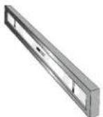
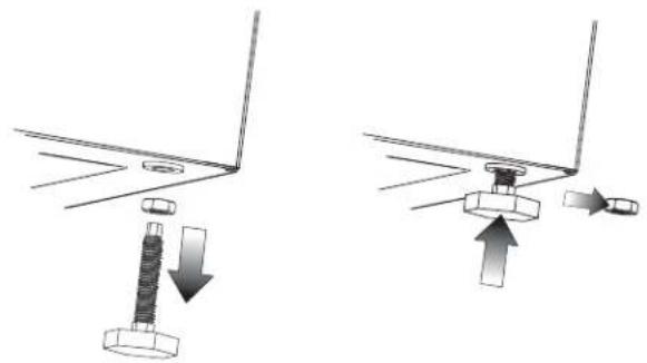
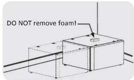
If appliance has plastic feet, screw each foot fl ush to the base.4.
If appliance has metal feet, unscrew them, remove the locking 5. nut and reinstall the feet flush to the base.
natural_image
Diagram showing two mechanical assembly steps with arrows indicating motion (no text or symbols)NOTE If locking nuts are not removed on units with metal feet, mounting holes in appliance will not align to mounting holes in brackets.
B) Preparing pedestal before mounting washer or dryer
Locate pedestal to within a few inches of its final location.1.
NOTE Allow for approximately 5 in. (12.5 cm) behind the pedestal for clearance of back of washer or dryer to the wall. Allow additional space if venting dryer upward or downward.
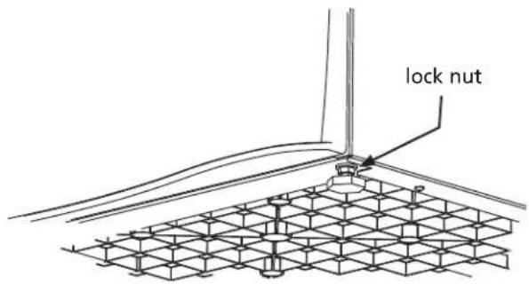
Level the pedestal front-to-back and side-to-side by adjusting 2. each leveling leg. Keep leg extension to a minimum.
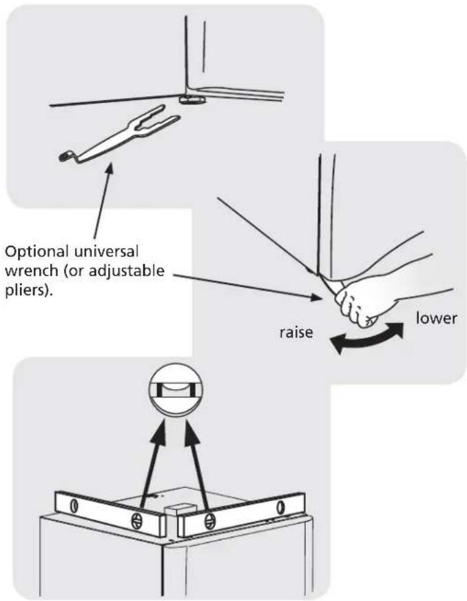
Rock the pedestal from corner-to-corner to check for stability. 3. Repeat leveling and rocking until all four (4) feet are sturdy on the floor and pedestal is level.
natural_image
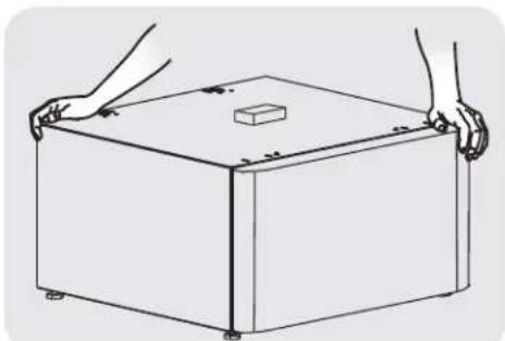
Line drawing of a rectangular box with two hands holding it, featuring a small cube on top (no text or symbols)Without turning the rubber foot, lock each pedestal leg in place 4. by tightening its lock nut tight against the pedestal base.
C1) Attaching washer mounting hardware
Use the following instructions for mounting either of these types 1. of washers to the pedestal:
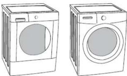
natural_image
Line drawings of two washing machines side by side, no text or symbols presentAttach each front clip to outer-most set of holes with 2 screws 2. and supplied spacer.
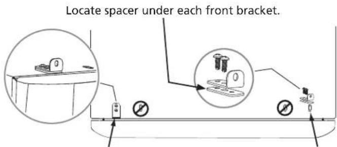
Insert "A" tab of each rear bracket into the middle slots on rear 3. of pedestal. Orient bracket inward for washer mounting.
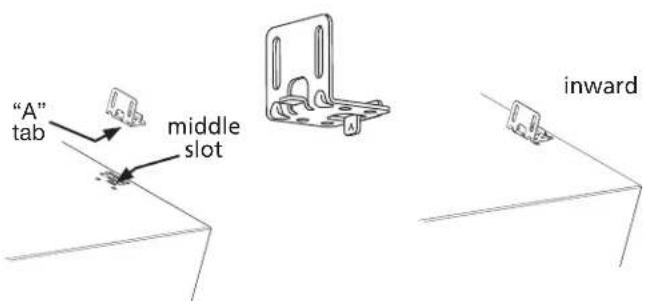
Install 2 screws through each rear bracket into aligning pedestal 4. holes.

natural_image
Line drawing of a sewing machine needle stitching a flat surface (no text or symbols)D1) Mounting washer
CAUTION - EXCESSIVE WEIGHT HAZARD - To avoid back or other injury, have more than one person move or lift the washer.
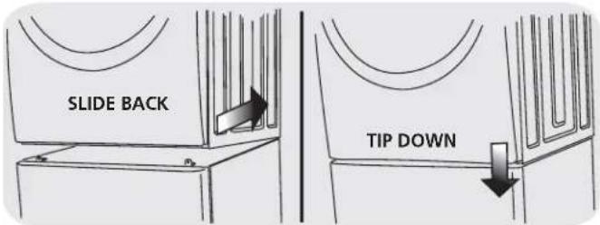
Using two or more persons, slightly tip the washer back and lift it 1. onto the pedestal. Still tipped, slide the washer back against the rear brackets and gently set down the front so the appliance is between the front and rear brackets.
Adjust the appliance side-to-side to align its mounting holes with 2. the pedestal's bracket holes.
Install 2 screws through each rear bracket into the base of the 3. washer.
natural_image
Technical line drawing of a mechanical assembly with no visible text or symbolsWith the pedestal drawer open for better access, install a screw 4. through each front bracket into the base of the washer.
natural_image
Line drawing of a hand pressing down on a mechanical component, with an inset showing a close-up of a small mechanical component (no text or symbols)E) Installing or re-installing washer
Slide appliance/pedestal into place.1.
Check for levelness and rock all four (4) legs again. Repeat until 2. level and solid.
Refer to 3. Washer Installation Instructions for complete details on installing water, drain, or electrical.
7.0 cu ft DRYER (STYLE 1) INSTRUCTIONS
C2) Attaching dryer (style 1) mounting hardware
Use the following instructions for mounting any of these types of 1 dryers to the pedestal:
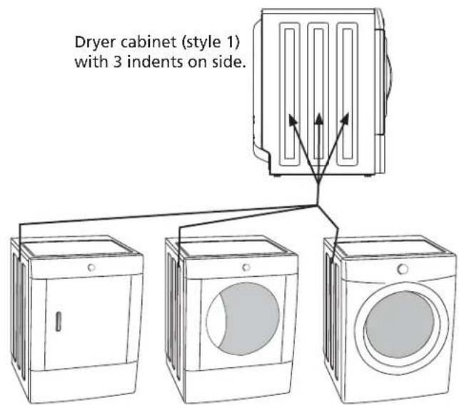
Attach each front clip to outer-most set of holes with 2 screws.2.
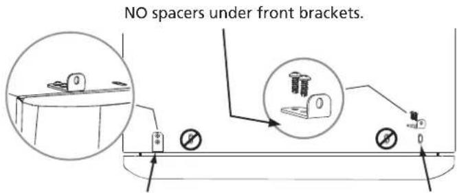
Insert "A" tab of each rear bracket into the rear slots on rear of 3. pedestal using rear bracket spacers. Orient bracket inward for "style 1" dryer mounting.
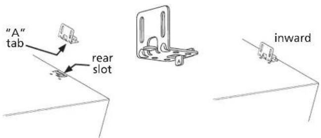
Install 2 screws through each rear bracket into aligning pedestal 4. holes.
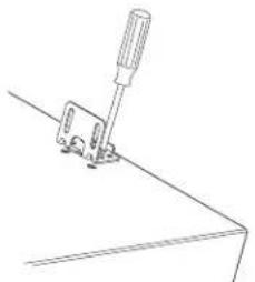
natural_image
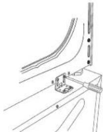
Line drawing of a mechanical clamp or bracket with a screwdriver inserted (no text or symbols)D2) Mounting dryer (style 1)
CAUTION - EXCESSIVE WEIGHT HAZARD - To avoid back or other injury, have more than one person move or lift the dryer.
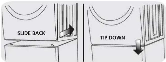
Using two or more persons, slightly tip the dryer back and lift it 1. onto the pedestal. Still tipped, slide the dryer back against the rear brackets and gently set down the front so the appliance is between the front and rear brackets.
Adjust the appliance side-to-side to align its mounting holes with 2. the pedestal's bracket holes.
Install 2 screws through each rear bracket into the base of the 3. dryer.
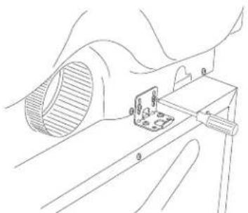
natural_image
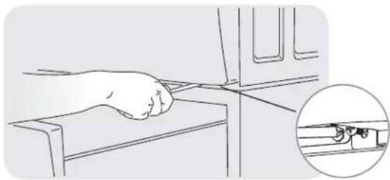
Technical line drawing of a mechanical assembly with a component inserted into a housing (no text or symbols)With the pedestal drawer open for better access, install a screw 4. through each front bracket into the base of the dryer.
natural_image
Line drawing of a hand using a tool to press or install a device, with an inset showing a close-up of the device (no text or symbols present)E) Installing or re-installing dryer (style 1)
Slide appliance/pedestal into place.1.
Check for levelness and rock all four (4) legs again. Repeat until 2. level and solid.
Refer to 3. Dryer Installation Instructions for complete details on installing electrical, gas, or exhaust venting.
5.8 cu ft DRYER (STYLE 2) INSTRUCTIONS
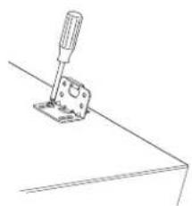
C3) Attaching dryer (style 2) mounting hardware
Use the following instructions for mounting any of these types of 1 dryers to the pedestal:
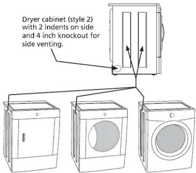
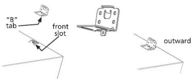
Attach each front clip to outer-most set of holes with 2 screws.2.
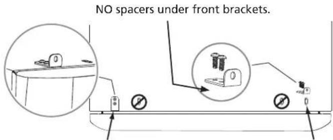
Insert "B" tab of each rear bracket into the front slots on rear of 3. pedestal. Orient bracket outward for "style 2" dryer mounting.
Install 2 screws through each rear bracket into aligning pedestal 4. holes.
natural_image
Line drawing of a screwdriver inserted into a bracket (no text or symbols)D3) Mounting dryer (style 2)
CAUTION - EXCESSIVE WEIGHT HAZARD - To avoid back or other injury, have more than one person move or lift the dryer.
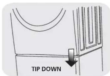
Using two or more persons, slightly tip the dryer back and lift it 1. onto the pedestal. Still tipped, slide the dryer back against the rear brackets so tabs on rear brackets engage the slots on the back of the dryer. Gently set down the front so the appliance is between the front and rear brackets.
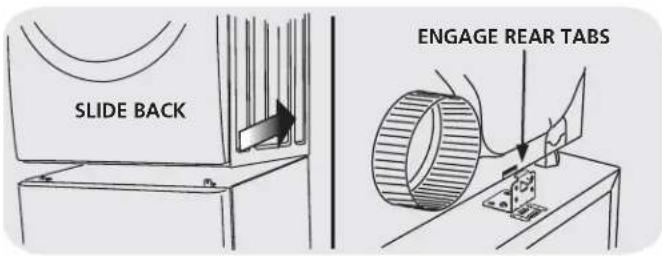
Adjust the appliance side-to-side to align its mounting holes with 2. the pedestal's bracket holes.
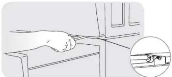
With the pedestal drawer open for better access, install a screw 3. through each front bracket into the base of the dryer.

natural_image
Line drawing of a hand gripping a device with a magnified inset showing a small mechanical component (no text or symbols)E) Installing or re-installing dryer (style 2)
Slide appliance/pedestal into place.1.
Check for levelness and rock all four (4) legs again. Repeat until 2. level and solid.
Refer to 3. Dryer Installation Instructions for complete details on installing electrical, gas, or exhaust venting.
REMARQUE
natural_image
Diagram showing a mechanical assembly with a bolt and nut, no text or symbols present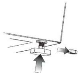
natural_image
Diagram showing a mechanical assembly with an upward arrow and directional arrows, no text or symbols present.REMARQUE
natural_image
Line drawing of a rectangular box with two hands holding it, featuring a small cube on top (no text or symbols)natural_image
Line drawings of two washing machines side by side, no text or symbols presentnatural_image
Line drawing of a screwdriver inserted into a workpiece on a flat surface (no text or symbols)natural_image
Technical line drawing of a mechanical assembly with numbered components (no text or symbols)natural_image
Line drawing of a hand using a tool to adjust or install a mechanical component, with an inset showing a close-up of the component (no text or symbols present)natural_image
Line drawing of a mechanical clamp or bracket with a screwdriver inserted (no text or symbols)natural_image
Technical line drawing of a mechanical assembly with no visible text or symbolsnatural_image
Line drawing of a hand pressing down on a mechanical component, with an inset showing a close-up of the component (no text or symbols)natural_image
Simple line drawing of a screwdriver pressing a component on a flat surface (no text or symbols)natural_image
Line drawing of a hand pressing down on a laptop keyboard, with an inset showing a close-up of the keyboard (no text or symbols)natural_image
Diagram showing two mechanical assembly states with arrows indicating motion, no text or symbols presentnatural_image
Line drawing of a rectangular box with a small square on top, being handled by two hands (no text or symbols)natural_image
Line drawings of two washing machines side by side, no text or symbols presentnatural_image
Line drawing of a sewing machine needle stitching a flat surface (no text or symbols)natural_image
Technical line drawing of a mechanical assembly with no visible text or symbolsnatural_image
Line drawing of a hand pressing down on a mechanical component, with an inset showing a close-up of the handle (no text or symbols)natural_image
Line drawing of a mechanical clamp or bracket with a screwdriver inserted (no text or symbols)natural_image
Technical line drawing of a mechanical assembly with a cylindrical component and mounting bracket (no text or symbols)natural_image
Line drawing of a hand using a tool to press or install a device on a mechanical component, with an inset showing a close-up of the device (no text or symbols present)natural_image
Line drawing of a screwdriver pressing a lever on a flat surface (no text or symbols)natural_image
Illustration of a hand pressing down on a mechanical component, with an inset showing a close-up of the handle (no text or symbols)Full One Year Warranty on Mechanical Parts
For one year from date of purchase, when this pedestal is installed with the listed washer or dryer (see owners manual for specific model) and operated according to the information in the Use and Care Guide, Operating Instructions and Installation Instructions, the supplier will repair or replace any of its mechanical parts if they are defective in workmanship or material. Keep your bill of sale. The date of the bill establishes the warranty period should parts be required. This written warranty gives you specific rights. You may also have other rights which vary from state to state.
Warranty Restriction
If the pedestal is used for any other purpose than private family use or used with any product that requires modification for installation, the warranty is null and void.
Warranty Parts
Warranty parts are available by contacting the supplier where the pedestal was purchased or refer to the Use and Care Guide that came with the washer or dryer that is installed on the pedestal for contact information.
PRODUCT RECORD
In the space below, record the date of purchase and model number of the product.
Model No.:
Date of Purchase:
Save these instructions and your sales receipt for future reference.
GARANTIE


- Installation Instructions
- KIT COMPONENTS:
- COMPOSANTS DU NÉCESSAIRE:
- AVERTISSEMENT
- A) Preparing washer or dryer for mounting on pedestal
- B) Preparing pedestal before mounting washer or dryer
- C1) Attaching washer mounting hardware
- D1) Mounting washer
- E) Installing or re-installing washer
- cu ft DRYER (STYLE 1) INSTRUCTIONS
- C2) Attaching dryer (style 1) mounting hardware
- D2) Mounting dryer (style 1)
- E) Installing or re-installing dryer (style 1)
- cu ft DRYER (STYLE 2) INSTRUCTIONS
- C3) Attaching dryer (style 2) mounting hardware
- D3) Mounting dryer (style 2)
- E) Installing or re-installing dryer (style 2)
- REMARQUE
- Full One Year Warranty on Mechanical Parts
- Warranty Restriction
- Warranty Parts
- PRODUCT RECORD
- GARANTIE
Brand : FRIGIDAIRE
Model : APWD15E
Category : Tumble dryer