
Affinity 7.0 cu FAQE7001LW - Tumble dryer FRIGIDAIRE - Free user manual and instructions
Find the device manual for free Affinity 7.0 cu FAQE7001LW FRIGIDAIRE in PDF.


| Product Type | Tumble Dryer |
| Brand | Frigidaire |
| Model | Affinity 7.0 cu. ft. FAQE7001LW |
| Capacity | 7.0 cu. ft. |
| Drying System | Vented |
| Energy Source | Electric |
| Voltage | 240 V |
| Power Consumption | ~5000 W |
| Dimensions (Width x Depth x Height) | 27" x 38" x 36" |
| Weight | 120 lbs |
| Door Type | Front Load |
| Dryer Cycles | Normal, Heavy Duty, Delicates, Quick Dry, Timed Dry, Perm Press |
| Key Features | Moisture Sensor, Wrinkle Prevent, End-of-Cycle Signal, Drum Light |
| Control Type | Electronic with LED Display |
| Lint Filter | Top-mounted, washable mesh |
| Drum Material | Stainless Steel |
| Energy Star Certified | Yes |
| Noise Level | ~65 dB |
| Safety Features | Child Lock, Thermal Fuse, Safety Start |
| Maintenance | Clean lint filter after each use; clean exhaust duct annually |
| Accessories Included | User manual, vent kit (optional) |
| Warranty | 1 year limited parts and labor |
| Spare Parts Availability | Belts, heating elements, sensors, door parts, controls |
| Repairability | Modular design; common parts easily replaceable |
Frequently Asked Questions - Affinity 7.0 cu FAQE7001LW FRIGIDAIRE
User questions about Affinity 7.0 cu FAQE7001LW FRIGIDAIRE
0 question about this device. Answer the ones you know or ask your own.
Ask a new question about this device
Download the instructions for your Tumble dryer in PDF format for free! Find your manual Affinity 7.0 cu FAQE7001LW - FRIGIDAIRE and take your electronic device back in hand. On this page are published all the documents necessary for the use of your device. Affinity 7.0 cu FAQE7001LW by FRIGIDAIRE.
USER MANUAL Affinity 7.0 cu FAQE7001LW FRIGIDAIRE
natural_image
Line drawing of various household appliances including washing machines, refrigerators, and a refrigerator (no text or symbols)TABLE OF CONTENTS
Important Safety Instructions 2-3
Installation Requirements 4-10
Installed Dryer Dimensions 11
Installation Instructions 12-17
Reversing Door 18-21
Accessories....22
Español 23
IMPORTANT SAFETY INSTRUCTIONS

WARNING
For your safety the information in this manual must be followed to minimize the risk of fire or explosion or to prevent property damage, personal injury or loss of life. Do not store or use gasoline or other flammable vapors and liquids in the vicinity of this or any other appliance.
⚠ WARNING - RISK OF FIRE
Read all of the following instructions before installing and using this appliance:
- Destroy the carton and plastic bags after the dryer is unpacked. Children might use them for play. Cartons covered with rugs, bedspreads, or plastic sheets can become airtight chambers causing suffocation. Place all materials in a garbage container or make materials inaccessible to children.
- Clothes dryer installation and service must be performed by a qualified installer, service agency or the gas supplier. Install the clothes dryer according to the manufacturer's instructions and local codes.
The electrical service to the dryer must conform with local codes and ordinances and the latest edition of the Na•tional Electrical Code, ANSI/NFPA 70, or in Canada, the Canadian electrical code C22.1 part 1.
The gas service to the dryer must conform with local codes and ordinances and the latest edition of the National Fuel Gas Code ANSI Z223.1, or in Canada, CAN/ACG B149.1-2000.
The dryer is designed under ANSI Z 21.5.1 or ANSI/UL 2158 - CAN/CSA C22.2 No. 112 (latest editions) for HOME • USE only. This dryer is not recommended for commercial applications such as restaurants, beauty salons, etc.
- Do not install a clothes dryer with flexible plastic venting material. Flexible venting materials are known to collapse, be easily crushed and trap lint. These conditions will obstruct clothes dryer airflow and increase the risk of fire.
Do not stack a dryer on top of washer already installed on pedestal. Do not stack washer on top of dryer. Do not • stack washer on top of another washer.
The instructions in this manual and all other literature included with this dryer are not meant to cover every possible condition and situation that may occur. Good safe practice and caution MUST be applied when installing, operating and maintaining any appliance.
WHAT TO DO IF YOU SMELL GAS:
Do not try to light any appliance.
Do not touch any electrical switch; do not use any phone in your building.
Clear the room, building or area of all occupants.
- Immediately call your gas supplier from a neighbor's phone. Follow the gas supplier's instructions.
- If you cannot reach your gas supplier, call the fire department.
Save these instructions for future reference.
Pre-Installation Requirements
Tools and materials needed for installation:
- Adjustable pliers
• Phillips, straight, & square bit screwdrivers - Adjustable wrench
- Pipe wrench for gas supply (gas dryer)
-
LP-resistant thread tape (for natural gas or LP supply, gas dryer)
-
Carpenter's level
- External vent hood
- 4-inch (102 mm), rigid metal or semi-rigid metal exhaust duct work
• 3-wire or 4-wire 240 volt cord kit (electric dryer)
• 4 in. (102 mm) clamp
• Gas line shutoff valve (gas dryer)
- 12 NPT union flare adapters (x2) and fl exible gas supply line (gas dryer)
• Metal foil tape (not duct tape)

WARNING
Please read all instructions before using this dryer.
Recognize safety symbols, words and labels
Safety items throughout this manual are labeled with a WARNING or CAUTION based on the risk type as described below:
Definitions
This is the safety alert symbol. It is used to alert you to potential personal injury hazards. Obey all safety messages that follow this symbol to avoid possible injury or death.

DANGER
DANGER indicates an imminently hazardous situation which, if not avoided, will result in death or serious injury.

WARNING
WARNING indicates a potentially hazardous situation which, if not avoided, could result in death or serious injury.

CAUTION
CAUTION indicates a potentially hazardous situation which, if not avoided, may result in minor or moderate injury.

IMPORTANT
IMPORTANT indicates installation, operation or maintenance information which is important but not hazard-related.

Installation Checklist
Exhaust Venting
☐ Free-flowing, clear of lint buildup
☐ 4 inch (102 mm) rigid or semi-rigid ducting of minimal length and turns
☐ NO foil or plastic venting material
☐ Approved vent hood exhausted to outdoors
Leveling
☐ Dryer is level, side-to-side and front-to-back
□ Cabinet is setting solid on all corners
Gas Supply (Gas Dryer)
☐ Manual shutoff valve present in supply
☐ All connections sealed with approved sealer and wrench tight
□ Conversion kit for LP system
☐ Gas supply turned on
☐ No leaks present at all connections - check with soapy water, NEVER check with fl ame
240v Electric Supply (Electric Dryer)
☐ Approved NEMA 10-30R or 14-30R service cord with all screws tight on terminal block
☐ Approved strain relief installed
☐ Terminal access cover installed before initial operation
Door Reversal
☐ Follow detailed instructions in this guide
☐ Test hinge and latch for function
Electrical Power
□ House power turned on
□ Dryer plugged in
Final Checks
☐ Installation Instructions and Use and Care Guide read thoroughly
☐ Door latches and drum tumbles when cycle starts
☐ Registration card sent in
INSTALLATION REQUIREMENTS

NOTE
Because of potentially inconsistent voltage capabilities, the use of this dryer with power created by gas powered generators, solar powered generators, wind powered generators or any other generator other than the local utility company is not recommended.
Electrical requirements for electric dryer
CIRCUIT - Individual 30 amp. branch circuit fused with 30 amp. time delay fuses or circuit breakers. Use separately fused circuits for washer and dryer. DO NOT operate a washer and a dryer on the same circuit.
POWER SUPPLY - 3-wire or 4-wire, 240 volt, single phase, 60 Hz, Alternating Current.

IMPORTANT
This dryer is internally grounded to neutral unless it was manufactured for sale in Canada. Grounding through the neutral link is prohibited for: (1) new branch circuit installations, (2) mobile homes, (3) recreational vehicles, and (4) areas where local codes do not permit grounding through the neutral.
OUTLET RECEPTACLE - NEMA 10-30R or NEMA 14-30R receptacle to be located so the power supply cord is accessible when the dryer is in the installed position.
GROUNDING CONNECTION - See "Grounding requirements" in Electrical Installation section.
3-WIRE POWER SUPPLY CORD KIT (not supplied)

3-wire receptacle (NEMA type 10-30R)
The dryer MUST employ a 3-conductor power supply cord NEMA 10-30 type SRDT rated at 240 volt AC minimum, 30 amp, with 3 open end spade lug connectors with upturned ends or closed loop connectors and marked for use with clothes dryers. For 3-wire cord connection instructions see ELECTRICAL CONNECTIONS FOR A 3-WIRE SYSTEM.
4-WIRE POWER SUPPLY CORD KIT (not supplied)

4-wire receptacle (NEMA type 14-30R)
The dryer MUST employ a 4-conductor power supply cord NEMA 14-30 type SRDT or ST (as required) rated at 240 volt AC minimum, 30 amp, with 4 open end spade lug connectors with upturned ends or closed loop connectors and marked for use with clothes dryers. For 4-wire cord connection instructions see ELECTRICAL CONNECTIONS FOR A 4-WIRE SYSTEM.

NOTE
Dryers manufactured for sale in Canada have factory-installed, 4-wire power supply cord (NEMA 14-30R).
Electrical requirements for gas dryer
CIRCUIT - Individual, properly polarized and grounded 15 amp. branch circuit fused with 15 amp. time delay fuse or circuit breaker.
POWER SUPPLY - 2-wire, with ground, 120 volt, single phase, 60 Hz, Alternating Current.
POWER SUPPLY CORD - The dryer is equipped with a 120 volt 3-wire power cord.
GROUNDING CONNECTION - See "Grounding requirements" in Electrical Installation section.
Gas supply requirements

WARNING
EXPLOSION HAZARD
Uncoated copper tubing will corrode when subjected to natural gas, causing gas leaks. Use ONLY black iron, stainless steel, or plastic-coated brass piping for gas supply.
1 Installation MUST conform with local codes, or in the absence of local codes, with the National Fuel Gas Code, ANSI Z223.1 (latest edition).
2 The gas supply line should be 1/2 inch (1.27 cm) pipe.
3 If codes allow, flexible metal tubing may be used to connect your dryer to the gas supply line. The tubing MUST be constructed of stainless steel or plastic-coated brass.
4 The gas supply line MUST have an individual shutoff valve.
5 A 1/8 inch (0.32 cm) N.P.T. plugged tapping, accessible for test gauge connection, MUST be installed immediately upstream of the gas supply connection to the dryer.
6 The dryer MUST be disconnected from the gas supply piping system during any pressure testing of the gas supply piping system at test pressures in excess of 1/2 psig (3.45 kPa).
7 The dryer MUST be isolated from the gas supply piping system during any pressure testing of the gas supply piping system at test pressures equal to or less than 1/2 psig (3.45 kPa).
8 Connections for the gas supply must comply with the Standard for Connectors for Gas Appliances, ANSI Z21.24.
INSTALLATION REQUIREMENTS
Exhaust system requirements
Use only 4 inch (102 mm) diameter (minimum) rigid or fl exible metal duct and approved vent hood which has a swing-out damper(s) that open when the dryer is in operation. When the dryer stops, the dampers automatically close to prevent drafts and the entrance of insects and rodents. To avoid restricting the outlet, maintain a minimum of 12 inches (30.5 cm) clearance between the vent hood and the ground or any other obstruction.

WARNING
FIRE HAZARD
Failure to follow these instructions can create excessive drying times and fire hazards.
The following are specific requirements for proper and safe operation of your dryer.

WARNING
FIRE HAZARD
Do not install a clothes dryer with fl exible plastic or metal foil venting materials. Flexible venting materials are known to collapse, be easily crushed and trap lint. These conditions will obstruct clothes dryer airfl ow and increase the risk of fi re.
If your present system is made up of plastic duct or metal foil duct, replace it with a rigid or semi-rigid metal duct. Also, ensure the present duct is free of any lint prior to installing dryer duct.


Exhaust system requirements, continued

WARNING
FIRE HAZARD
A clothes dryer must be exhausted outdoors. Do not exhaust dryer into a chimney, a wall, a ceiling, an attic, a crawl space or any concealed space of a building. A clothes dryer produces combustible lint. If the dryer is not exhausted outdoors, some fi ne lint will be expelled into the laundry area. An accumulation of lint in any area of the home can create a health and fi re hazard.
The dryer must be connected to an exhaust outdoors. Regularly inspect the outdoor exhaust opening and remove any accumulation of lint around the outdoor exhaust opening and in the surrounding area.

WARNING
FIRE HAZARD
Do not allow combustible materials (for example: clothing, draperies/curtains, paper) to come in contact with exhaust system. The dryer MUST NOT be exhausted into a chimney, a wall, a ceiling, or any concealed space of a building which can accumulate lint, resulting in a fi re hazard. Do not screen the exhaust ends of the vent system, or use any screws, rivets or other fasteners that extend into the duct to assemble the exhaust system. Lint can become caught in the screen, on the screws or rivets, clogging the duct work and creating a fi re hazard as well as increasing drying times. Use an approved vent hood to terminate the duct outdoors, and seal all joints with duct tape. All male duct pipe fi ttings MUST be installed downstream with the flow of air.

WARNING
FIRE HAZARD
Exceeding the length of duct pipe or number of elbows allowed in the "MAXIMUM LENGTH" charts can cause an accumulation of lint in the exhaust system. Plugging the system could create a fire hazard, as well as increase drying times.
| Number of 90° turns | MAXIMUM LENGTHof 4" (102mm) Rigid Metal Duct | ||
| VENT HOOD TYPE | |||
| (Preferred) | |||
 |  erei erei |  | |
| 0 64 | ft. (19.5 m) 48 ft. (14.6 m) | ||
| 1 52 | ft. (15.9 m) 40 ft. (12.2 m) | ||
| 2 44 | ft. (13.5 m) 32 ft. (9.8 m) | ||
| 3 32 | ft. (9.8 m) 24 ft. (7.3 m) | ||
| 4 28 | ft. (9.5 m) 16 ft. (4.9 m) | ||

WARNING
FIRE HAZARD
- Do not install flexible plastic or flexible foil venting material.
If installing semi-rigid venting, do not exceed 8 ft. • (2.4 m) duct length.
INSTALLATION REQUIREMENTS
Exhaust system requirements, continued
Install male fi ttings in correct direction:
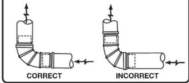
In installations where the exhaust system is not described in the charts, the following method must be used to determine if the exhaust system is acceptable:
1 Connect an inclined or digital manometer between the dryer and the point the exhaust connects to the dryer.
2 Set the dryer timer and temperature to air fluff (cool down) and start the dryer.
3 Read the measurement on the manometer.
4 The system back pressure MUST NOT be higher than 0.75 inches of water column. If the system back pressure is less than 0.75 inches of water column, the system is acceptable. If the manometer reading is higher than .075 inches of water column, the system is too restrictive and the installation is unacceptable.
Although vertical orientation of the exhaust system is acceptable, certain extenuating circumstances could affect the performance of the dryer:
Only the rigid metal duct work should be used. Venting vertically through a roof may expose the exhaust system to down drafts causing an increase in vent restriction.
Running the exhaust system through an • uninsulated area may cause condensation and faster accumulation of lint.
Compression or crimping of the exhaust system will cause an increase in vent restriction.
The exhaust system should be inspected and cleaned a minimum of every 18 months with normal usage. The more the dryer is used, the more often you should check the exhaust system and vent hood for proper operation.
Exhaust direction
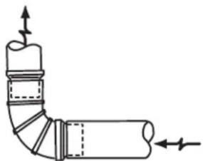
Directional exhausting can be accomplished by installing a quick-turn 90° dryer vent elbow directly to exhaust outlet of dryer. Dryer vent elbows are available through your local parts distributor or hardware store.

natural_image
Technical line drawing of a vehicle interior showing airflow or pressure direction (no text or symbols)See also CLEARANCE REQUIREMENTS on the next page.

NOTE
Use of 90° quick-turn elbow required to meet minimum installation depth of free-standing dryer:
Straight back venting allows for 0" (0 cm) installation. Venting right with 90° elbow allows for 0.75" (2 cm) installation.
Venting downward with 90° elbow allows for 0.75" (2 cm) installation.
Venting left with short, straight adapter and 90° • elbow allows for 3.75" (9.5 cm) installation.
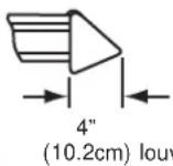
Venting upward with short, straight adapter and 90° elbow allows for 4" (10.5 cm) installation.
Manufactured or mobile home installation
1 Installation MUST conform to current Manufactured Home Construction & Safety Standard, Title 24 CFR, Part 32-80 (formerly the Federal Standard for Mobile Home Construction and Safety, Title 24, HUD Part 280) or Standard CAN/CSAZ240 MH.
2 Dryer MUST be exhausted outside (outdoors, not beneath the mobile home) using metal ducting that will not support combustion. Metal ducting must be 4 inches (10.16 cm) in diameter with no obstructions. Rigid metal duct is preferred.
3 If dryer is exhausted through the floor and area beneath the mobile home is enclosed, the exhaust
system MUST terminate outside the enclosure with the termination securely fastened to the mobile home structure.
4 Refer to previous sections in this guide for other important exhaust venting system requirements.
5 When installing a gas dryer into a mobile home, a provision must be made for outside make up air. This provision is to be not less than twice the area of the dryer exhaust outlet.
6 Installer MUST anchor this (1) dryer or (2) dryer mounted on pedestal to the floor with approved Mobile Home Installation Kit - P/N 137067200.
Clearance requirements

WARNING
EXPLOSION HAZARD
Do not install the dryer where gasoline or other fl immables are kept or stored. If the dryer is installed in a garage, it must be a minimum of 18 inches (45.7 cm) above the floor. Failure to do so can result in death, explosion, fire or burns.

IMPORTANT
DO NOT INSTALL YOUR DRYER:
1 In an area exposed to dripping water or outside weather conditions.
2 In an area where it will come in contact with curtains, drapes, or anything that will obstruct the flow of combustion and ventilation air.
3 On carpet. Floor MUST be solid with a maximum slope of 1 inch (2.54 cm).
INSTALLATION REQUIREMENTS
Clearance requirements, continued
Installation in a Recess or Closet
1 A dryer installed in a bedroom, bathroom, recess or closet, MUST be exhausted outdoors.
2 No other fuel burning appliance shall be installed in the same closet as the gas dryer.
3 Your dryer needs the space around it for proper ventilation.
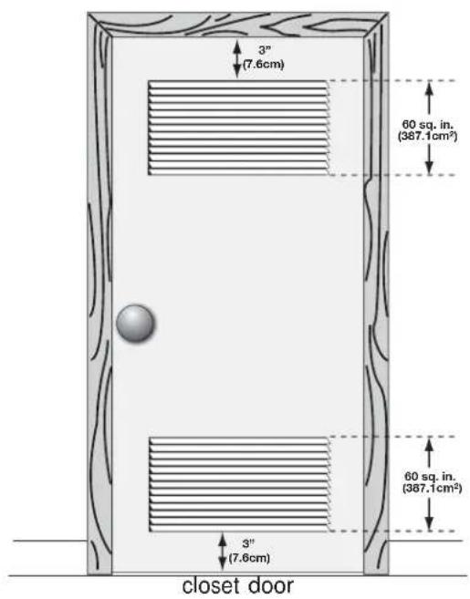
DO NOT install your dryer in a closet with a solid door.
4 Closet door ventilation required: A minimum of 120 square inches (774.2 cm²) of opening, equally divided at the top and bottom of the door, is required. Openings should be located 3 inches (7.6 cm) from bottom and top of door. Openings are required to be unobstructed when a door is installed. A louvered door with equivalent air openings for the full length of the door is acceptable.
| MINIMUM INSTALLATION CLEARANCES - Inches (cm) | ||||
| SIDES REAR TOP FRONT | ||||
| Alcove 0" | (0 cm) 0" | (0 cm)* 0" | (0 cm) n/a | |
| Under-Counter | 0" (0 cm) | 0" (0 cm)* | 0" (0 cm) | n/a |
| Closet 0" | (0 cm) 0" | (0 cm)* 0" | (0 cm) 1" | 2.54 cm) |
For other than straight back venting, a quick-turn * 90° dryer vent elbow (vented right or down in freestanding dryer or right on pedestal-mounted dryer) must be installed to achieve 0" (0 cm) installation.


NOTE
To achieve an installation with 0" (0 cm) clearance for the back of the dryer (for other than straight back venting), a quick-turn 90° dryer vent elbow must be installed as described previously in this manual.
INSTALLED DIMENSIONS

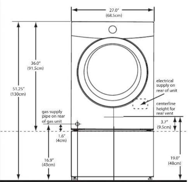
* To obtain these minimal depth dimensions, dryer must be vented straight back. Using a quick-turn 90° elbow (right or down on freestanding dryer) adds approximately 0.75 in. (2.0 cm) to installation depth. Upward venting of exhaust on pedestal-mounted or freestanding dryer adds approximately 4 in. (10.2 cm) to installation depth. Leftward venting on pedestal-mounted or freestanding dryer adds approximately 3.75 in. (9.5 cm) to Installation depth. Downward venting of exhaust on pedestal-mounted dryer adds approximately 2.25 in. (5.7 cm) to Installation depth.


* To obtain these minimal depth dimensions, dryer must be vented straight back. Using a quick-turn 90° elbow (right) adds approximately 0.75 in. (2 cm) to installation depth. Upward venting of exhaust on stacked dryer adds approximately 4 in. (10.2 cm) to Installation depth. Downward venting of exhaust on stacked dryer adds approximately 2.25 in. (6.5 cm) to installation depth. Leftward venting of exhaust on stacked dryer adds approximately 3.75 in. (9.5 cm) to Installation depth.
INSTALLATION INSTRUCTIONS
Electrical installation
The following are specific requirements for proper and safe electrical installation of your dryer. Failure to follow these instructions can create electrical shock and/or a fire hazard.

WARNING
ELECTRICAL SHOCK HAZARD
This appliance MUST be properly grounded. • Electrical shock can result if the dryer is not properly grounded. Follow the instructions in this manual for proper grounding. Do not use an extension cord with this dryer. Some • extension cords are not designed to withstand the amounts of electrical current this dryer utilizes and can melt, creating electrical shock and/or fi re hazard. Locate the dryer within reach of the receptacle for the length power cord to be purchased, allowing some slack in the cord. Refer to the pre-installation requirements in this manual for the proper power cord to be purchased.

WARNING
ELECTRICAL SHOCK HAZARD
A U.L.-approved strain relief must be installed onto power cord. If the strain relief is not attached, the cord can be pulled out of the dryer and can be cut by any movement of the cord, resulting in electrical shock.
Do not use an aluminum wired receptacle with a copper wired power cord and plug (or vice versa).
A chemical reaction occurs between copper and aluminum and can cause electrical shorts. The proper wiring and receptacle is a copper wired power cord with a copper wired receptacle.

NOTE
Dryers operating on 208 volt power supply will have longer drying times than dryers operating on 240 volt power supply.
Grounding requirements - Electric dryer (USA)

WARNING
ELECTRICAL SHOCK HAZARD
Improper connection of the equipment grounding conductor can result in a risk of electrical shock. Check with a licensed electrician if you are in doubt as to whether the appliance is properly grounded.
For a grounded, cord-connected dryer:
1 The dryer MUST be grounded. In the event of a malfunction or breakdown, grounding will reduce the risk of electrical shock by a path of least resistance for electrical current.
2 After you purchase and install a 3 wire or 4 wire power supply cord having an equipment-grounding conductor and a grounding plug that matches you
wiring system, the plug MUST be plugged into an appropriate, copper wired receptacle that is properly installed and grounded in accordance with all local codes and ordinances. If in doubt, call a licensed electrician.
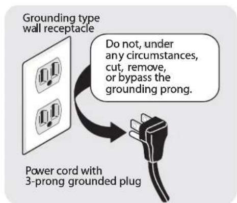
3 DO NOT modify the plug you've installed on this appliance. If it will not fit the outlet, have a proper outlet installed by a qualified electrician.
For a permanently connected dryer:
1 The dryer MUST be connected to a grounded metal, permanent wiring system; or an equipment grounding conductor must be run with the circuit conductors and connected to the equipment-grounding terminal or lead on the appliance.
Grounding requirements - Electric dryer (Canada)

WARNING
ELECTRICAL SHOCK HAZARD
Improper connection of the equipment grounding conductor can result in a risk of electrical shock. Check with a licensed electrician if you are in doubt as to whether the appliance is properly grounded.
For a grounded, cord-connected dryer:
1 The dryer MUST be grounded. In the event of a malfunction or breakdown, grounding will reduce
the risk of electrical shock by a path of least resistance for electrical current.
2 Since your dryer is equipped with a power supply cord having an equipment-grounding conductor and a grounding plug, the plug must be plugged into an appropriate outlet that is properly installed and grounded in accordance with all local codes and ordinances. If in doubt, call a licensed electrician.
3 DO NOT modify the plug provided with this appliance. If it will not fit the outlet, have a proper outlet installed by a qualified electrician.
Grounding requirements - Gas dryer (USA and Canada)
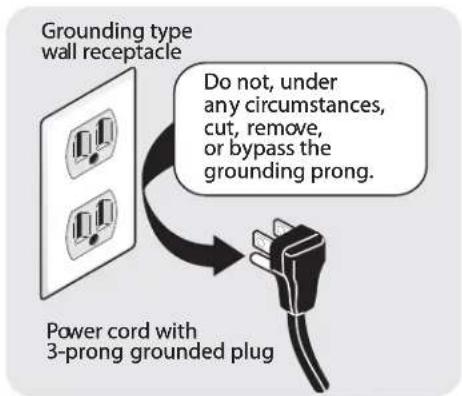
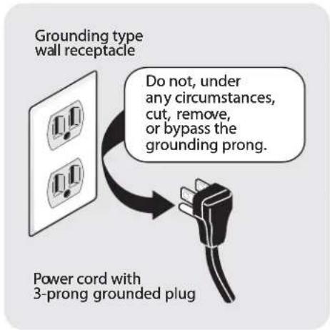
1 The dryer is equipped with a three-prong (grounding) plug for your protection against shock hazard and should be plugged directly into a properly grounded three-prong receptacle.
2 The plug must be plugged into an appropriate outlet that is properly installed and grounded in accordance with all local codes and ordinances. If in doubt, call a licensed electrician.
3 DO NOT modify the plug provided with this appliance. If it will not fit the outlet, have a proper outlet installed by a qualified electrician.
INSTALLATION INSTRUCTIONS
Gas connection
1 Remove the shipping cap from gas pipe at the rear of the dryer.

IMPORTANT
DO NOT connect the dryer to L.P. gas service without converting the gas valve. An L.P. conversion kit must be installed by a qualified gas technician.
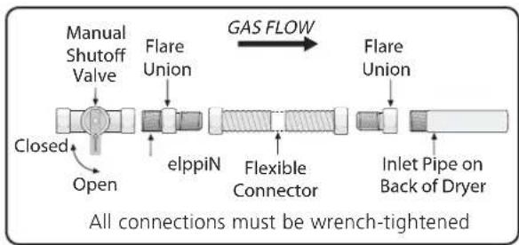
2 Connect a 1/2 inch (1.27 cm) I.D. semi-rigid or approved pipe from gas supply line to the 3/8 inch (0.96 cm) pipe located on the back of the dryer. Use a 1/2 inch to 3/8 inch (1.27 cm to 0.96 cm) reducer for the connection. Apply an approved thread sealer that is resistant to the corrosive action of liquefi ed gases on all pipe connections.
flowchart
graph LR
    A["Manual Shutoff Valve"] --> B["Closed"]
    B --> C["Open"]
    D["Flare Union"] --> E["elppiN"]
    E --> F["Flexible Connector"]
    F --> G["Inlet Pipe on Back of Dryer"]
    H["Flare Union"] --> I["GAS FLOW"]
    style A fill:#f9f,stroke:#333
    style D fill:#f9f,stroke:#333
    style H fill:#f9f,stroke:#333
    style I fill:#f9f,stroke:#333

IMPORTANT
The supply line must be equipped with an approved manual shutoff valve. This valve should be located in the same room as the dryer and should be in a location that allows ease of opening and closing. Do not block access to the gas shutoff valve.
3 Open the shutoff valve in the gas supply line to allow gas to flow through the pipe. Wait a few minutes for gas to move through the gas line.

4 Check for gas system leaks with a manometer. If a manometer is not available, test all connections by brushing on a soapy water solution.

WARNING
EXPLOSION HAZARD
NEVER test for gas leaks with an open flame.
Electrical connection (non-Canada) - 3 wire cord

3-wire receptacle
(NEMA type 10-30R)

WARNING
ELECTRICAL SHOCK HAZARD
Failure to disconnect power source before servicing could result in personal injury or even death.
1 Turn off power supply to outlet.
2 Remove the screw securing the terminal block access cover in the lower corner on the back of the dryer.
3 Install a UL-approved strain relief according to the power cord/strain relief manufacturer's instructions in the power cord entry hole below the access panel. At this time, the strain relief should be loosely in place.
4 Thread an UNPLUGGED, UL-approved, 30 amp. power cord, NEMA 10-30 type SRDT, through the strain relief.
5 Attach the power cord neutral (center wire) conductor to the SILVER colored center terminal on the terminal block. Tighten the screw securely.
6 Attach the remaining two power cord outer conductors to the outer, BRASS colored terminals on the terminal block. Tighten both screws securely.

WARNING
ELECTRICAL SHOCK HAZARD
Do not make a sharp bend or crimp wiring/conductor at connections.
7 Follow manufacturer's guidelines for firmly securing the strain relief and power cord.
8 Reinstall the terminal block cover.

IMPORTANT
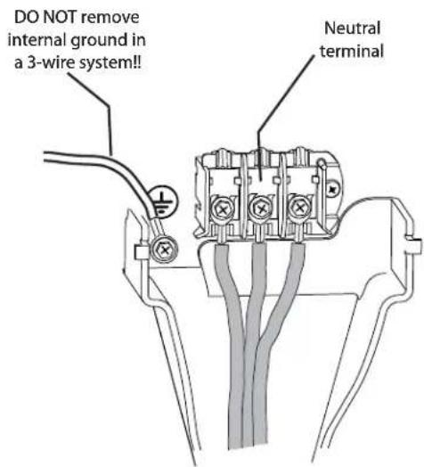
If moving dryer from a 4-wire system and installing it in a 3-wire system, move the internal ground from the center terminal back to the GREEN screw next to the terminal block.


NOTE
If a terminal screw falls during cord installation, it can be retrieved in the terminal screw recovery slot below the access panel.
INSTALLATION INSTRUCTIONS
Electrical connection (non-Canada) - 4 wire cord

4-wire receptacle (NEMA type 14-30R)

WARNING
ELECTRICAL SHOCK HAZARD
Failure to disconnect power source before servicing could result in personal injury or even death.
1 Turn off power supply to outlet.
2 Remove the screw securing the terminal block access cover in the lower corner on the back of the dryer.
3 Install a UL-approved strain relief according to the power cord/strain relief manufacturer's instructions in the power cord entry hole below the access panel. At this time, the strain relief should be loosely in place.
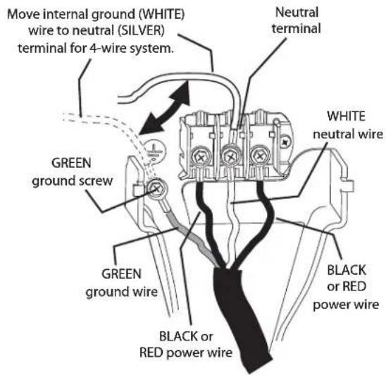
4 Thread an UNPLUGGED, UL-approved, 30 amp. power cord, NEMA 14-30 type ST or SRDT, through the strain relief.
5 Disconnect the internal (WHITE) dryer harness ground wire from the (GREEN) ground screw next to the terminal block.
6 Attach the ground (GREEN) power cord wire to the cabinet with the ground (GREEN) screw. Tighten the screw securely.
7 Move the internal dryer harness ground (WHITE) wire to the terminal block and attach it along with the neutral (WHITE) power cord wire conductor to the center, SILVER colored terminal on the terminal block. Tighten the screw securely.
8 Attach the RED and BLACK power cord conductors to the outer, BRASS colored terminals on the terminal block. Tighten both screws securely.

WARNING
ELECTRICAL SHOCK HAZARD
Do not make a sharp bend or crimp wiring/conductor at connections.
9 Follow manufacturer's guidelines for firmly securing the strain relief and power cord.
10 Reinstall the terminal block cover.


NOTE
If a terminal screw falls during cord installation, it can be retrieved in the terminal screw recovery slot below the access panel.
General installation
1 Connect the exhaust duct to the outside exhaust system (see pages 6 through 8). Use of a 4" (10.2 cm) clamp (item A) is recommended to connect the dryer to the exhaust vent system. Use metal foil tape to seal all other joints.
2 Carefully slide the dryer to its final position. Adjust one or more of the legs until the dryer is resting solidly on all four legs. Place a level on top of the dryer. The dryer MUST be level and resting solidly on all four legs. Rock alternating corners to check for stability. Remove and discard door tape.

IMPORTANT
Be sure the power is off at a circuit breaker/fuse box before plugging the power cord into an outlet.
3 Plug the power cord into a grounded outlet.
4 Turn on the power at the circuit breaker/fuse box.
5 Read the Use & Care Guide provided with the dryer. It contains valuable and helpful information that will save you time and money.
6 If you have any questions during initial operation, please review the "Avoid Service Checklist" in your Use & Care Guide before calling for service.
7 Place these instructions in a location near the dryer for future reference.

NOTE
A wiring diagram and technical data sheet are located inside the dryer console.

natural_image
Diagram of a mechanical component with labeled parts A and directional arrows (no text or symbols beyond labels)
natural_image
Diagram showing a washing machine with three circular insets illustrating the components of the door (no text or symbols present)
natural_image
Illustration of three electrical plug symbols: a three-pin socket, a three-pin plug with two leads, and a multi-pin plug with two leads (no text or labels)REVERSING DOOR
Removing the door
1 Protect flat work surface, such as top of dryer or floor near dryer, with a soft cloth or towel.
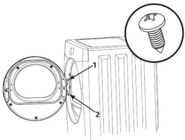
2 Open dryer door and remove the two hinge screws. Remove lower screw first, then upper screw.

3 Supporting door with both hands, squarely lift door and hinge upward approximately 3/8" (10 mm) so "T" post on back of hinge can slide out through "T" slot on front panel.

4 Gently place dryer door face down on flat, covered work surface.
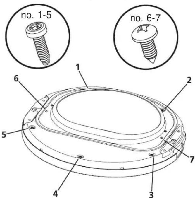
5 Locate the 5 indented head screws (no. 1-5) in the small, circular recesses (at 11, 1, 4, 6, and 8 o'clock positions) of the inner door. Remove and save these 5 screws.

IMPORTANT
Do not attempt to remove the 2 "tamper-resistant" screws that hold the inner glass in place.
6 Locate the 2 pan head screws (no. 6-7) on the inner door nearest the metal strike and center of hinge (9 and 3 o'clock positions). Remove and save these 2 screws.
7 Separate inner door assembly from outer door assembly.
Reversing the hinge
1 Carefully pull out the 2 small round hole plugs from the front panel and save. Remove and save the square "T" slot cover by sliding it up and pulling it out. Move all 3 plugs to the opposite side of the front panel and insert.

flowchart
graph TD
    A["ROUND PLUG"] --> B["SQUARE PLUG"]
    B --> C["ROUND PLUG"]
    C --> D["Square PLUG"]
    D --> A
    style A fill:#f9f,stroke:#333
    style B fill:#ccf,stroke:#333
    style C fill:#cfc,stroke:#333
    style D fill:#fcc,stroke:#333
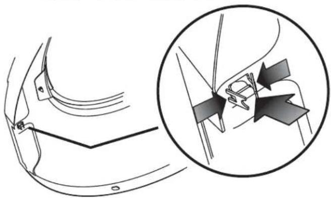
2 Turn inner door assembly over to expose retaining tabs of metal strike. Grip tabs fully with pliers to remove. Discard old metal strike.
natural_image
Technical diagram showing a car's side profile and its internal component assembly (no text or labels)3 Turn the inner door assembly back over and locate the 2 pan head hinge screws. Remove and save the 2 screws and separate the hinge from inner door assembly.

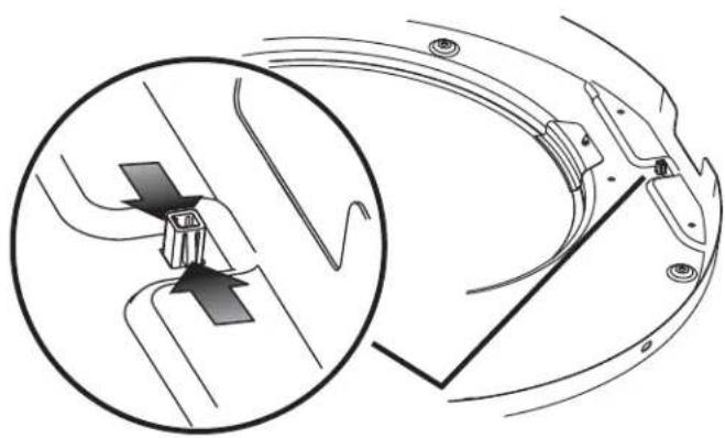
4 From the back side of the inner door, pinch the retaining tabs of the plastic square plug to release it. Save square plug for reinstallation.
natural_image
Technical diagram showing a mechanical component with an inset close-up of a fastener or clamp mechanism (no text or symbols present)5 Carefully remove the 2 round plugs from the inner door and move them to the opposite holes and reinstall.

6 Rotate the hinge and move it to the opposite side of the inner door. Attach it with the 2 pan head screws removed previously. Reinstall plastic plug in the square hole next to the hinge.

natural_image
Technical line drawing of a mechanical component with a magnified inset showing a screw (no text or symbols)REVERSING DOOR
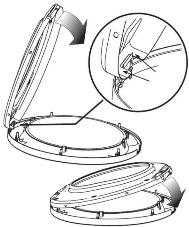
1 Locate and remove the hinge cutout gate from the outer door assembly. Rotate and move it to the opposite hole in the outer door.

natural_image
Technical line drawing of two circular mechanical components with mounting brackets and a directional arrow indicating motion (no text or symbols)2 Rest the opening of the inner door at a 90 degree angle on the "shoulders" of the hinge cutout gate. Pivot the inner door down onto the outer door.
natural_image
Technical illustration of a mechanical component with an open lid and internal assembly, showing a close-up view of the mechanism (no text or symbols present)3 Replace indented head screws (no. 1-5) removed earlier. Take care not to strip out the plastic holes. 4 Replace pan head screws (no. 6-7) removed earlier. Take care not to strip out the plastic holes.
5 Locate new metal strike supplied with dryer manuals. Grip new strike with pliers as shown below. Firmly insert the strike so it is oriented vertically.

natural_image
Line drawing of a tool in use on a curved mechanical component, showing a pliers and a handle (no text or symbols)Reattaching the door
1 Holding the door in both hands, squarely insert the "T" post on the back of the hinge into the "T" slot on the front panel and lower it to align the mounting holes.

2 While supporting the door, install the upper pan head screw first and then the lower one.

NOTE
Correctly installed hinge screws will press hinge fl ush to front panel. Any gap between hinge and front panel will cause misalignment of strike to latch.
3 Close the door and test operation of hinge, strike and latch.

natural_image
Diagram of curved mechanical components with a directional arrow, no text or symbols presentACCESSORIES
MATCHING STORAGE PEDESTAL\*
Classic White Pedestal - P/N CFPWD15W
Classic Blue Pedestal - P/N CFPWD15N
Classic Red Pedestal - P/N CFPWD15R
Classic Silver Pedestal - P/N CFPWD15A
Classic Black Pedestal - P/N CFPWD15B
A storage pedestal accessory, specifically designed for this dryer may be used to elevate the dryer for ease of use. This pedestal will add about 15" (38 cm) to the height of your unit for a total height of 51.25" (130 cm).
* Other colors may be available. Contact the source where you purchased your dryer.
DRYER STACKING KIT
P/N 134700600
Depending on the model you purchased, a kit for stacking this dryer on top of matching washer may have been included in the initial purchase of your dryer. If your model did not include a stacking kit or you desire another stacking kit, you may order one.
LP CONVERSION KIT
P/N PCK4200
Gas dryers intended for use in a location supplied with LP must use a conversion kit prior to installation.
MOBILE HOME INSTALLATION KIT
P/N 137067200
Installation in a mobile home requires the use of a MOBILE HOME INSTALLATION KIT.
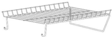
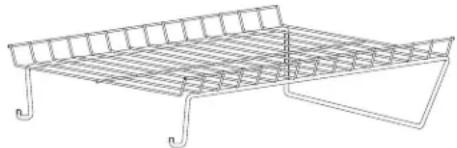
DRYING RACK
P/N 137067300
Depending on the model you purchased, a drying rack may have been included in the initial purchase of your dryer. If your model did not include a drying rack or you desire another drying rack, you may order one.
UNIVERSAL APPLIANCE WRENCH
P/N 137019200
A UNIVERSAL APPLIANCE WRENCH is available to aid in dryer/washer/pedestal feet adjustment.
TOUCH UP PAINT PENS\*
Classic White Touch Up Pen - P/N 5304468812
Classic Red Touch Up Pen - P/N 5304471227
Classic Blue Touch Up Pen - P/N 5304471229
Classic Silver Touch Up Pen - P/N 5304471228
Classic Black Touch Up Pen - P/N 5304458932
* Other colors may be available. Contact the source where you purchased your dryer.

CAUTION
Failure to use accessories manufactured by (or approved by) the manufacturer could result in personal injury, property damage or damage to the dryer.

natural_image
Line drawing of a metal rack with grid pattern and support legs (no text or symbols)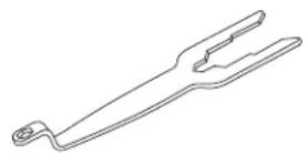
Replacement parts:
If replacements parts are needed for your washer, contact the source where you purchased your washer or refer to your Use and Care Guide for more information.

WARNING
ELECTRICAL SHOCK HAZARD
Label all wires prior to disconnection when servicing controls. Wiring errors can cause improper and dangerous operation. Verify proper operation after servicing.
Todo acerca del
Instalación
de su Secadora

natural_image
Line drawing of various household appliances including washing machines, refrigerators, and a refrigerator (no text or symbols)ÍNDICE
natural_image
Diagram of a pipe elbow joint with directional arrows indicating force or movement (no text or labels)CORRECTO
natural_image
Diagram of a bent pipe with directional arrows indicating flow or force (no text or symbols)INCORRECTO
natural_image
Technical diagram of a vehicle interior showing airflow or fluid flow around a valve (no text or symbols)puerta del armario
| ESPACIOS MÍNIMOS PARA LA INSTALACIÓN: cm (pulgadas) | ||||
| LATERALES | PARTE TRASERA | PARTE SUPERIOR | PARTE DELANTERA | |
| Alcôve 0 cm (0") 0 cm (0") 0 cm (0") | n/d | |||
| Sous le comptoir | 0 cm (0") 0 cm (0") 0 cm (0") n/d | |||
| Placard 0 cm (0") 0 cm (0") 0 cm (0") | 2,54 cm (1") | |||

NOTA

natural_image
Technical diagram showing a mechanical component with labeled parts A and directional arrows (no text or symbols beyond labels)
natural_image
Diagram showing a washing machine with side panels and a close-up of its front panel (no text or symbols present)
natural_image
Illustration of three electrical plug symbols: three-left, one with a terminal pin, one with a switch, and one with a fuse (no text or labels)IMPORTANTE
natural_image
Technical diagram showing a car interior with structural details and a magnified inset of the hand holding a tool (no text or symbols present)natural_image
Technical line drawing of a mechanical component with an inset showing a close-up of a pin fitting (no text or symbols)natural_image
Technical line drawing of a mechanical component with a magnified inset showing a screw detail (no text or symbols)natural_image
Technical line drawing of two circular mechanical components with mounting brackets and a directional arrow indicating motion (no text or symbols)natural_image
Technical illustration of a mechanical device with open lid and circular base, showing internal components and assembly steps (no text or symbols)natural_image
Line drawing of a tool in use on a curved mechanical component, showing a clamp and clamping device (no text or symbols)
NOTA
natural_image
Diagram of curved pipe or ducts with a directional arrow indicating flow or movement (no text or symbols)ACCESORIOS
PEDESTAL DE ALMACENAMI ENTO CONCORDANTE\*
Pedestal de color blanco - P/N CFPWD15W
Pedestal de color azul - P/N CFPWD15N
Pedestal de color rojo - P/N CFPWD15R
Pedestal de color plateada - P/N CFPWD15A
Pedestal de color negra - P/N CFPWD15B
natural_image
Line drawing of a wire mesh tray with metal frame and support structure (no text or symbols)
Piezas de repuesto:



- TABLE OF CONTENTS
- IMPORTANT SAFETY INSTRUCTIONS
- WARNING
- ⚠ WARNING - RISK OF FIRE
- WHAT TO DO IF YOU SMELL GAS:
- Save these instructions for future reference.
- Pre-Installation Requirements
- Recognize safety symbols, words and labels
- Definitions
- DANGER
- CAUTION
- IMPORTANT
- Installation Checklist
- Exhaust Venting
- Leveling
- Gas Supply (Gas Dryer)
- 240v Electric Supply (Electric Dryer)
- Door Reversal
- Electrical Power
- Final Checks
- INSTALLATION REQUIREMENTS
- NOTE
- Electrical requirements for electric dryer
- Electrical requirements for gas dryer
- Gas supply requirements
- EXPLOSION HAZARD
- Exhaust system requirements
- FIRE HAZARD
- Exhaust system requirements, continued
- Exhaust direction
- Manufactured or mobile home installation
- Clearance requirements
- Clearance requirements, continued
- Installation in a Recess or Closet
- INSTALLED DIMENSIONS
- INSTALLATION INSTRUCTIONS
- Electrical installation
- ELECTRICAL SHOCK HAZARD
- Grounding requirements - Electric dryer (USA)
- Grounding requirements - Electric dryer (Canada)
- Grounding requirements - Gas dryer (USA and Canada)
- Gas connection
- Electrical connection (non-Canada) - 3 wire cord
- Electrical connection (non-Canada) - 4 wire cord
- General installation
- REVERSING DOOR
- Removing the door
- Reversing the hinge
- Reattaching the door
- ACCESSORIES
- MATCHING STORAGE PEDESTAL\*
- DRYER STACKING KIT
- LP CONVERSION KIT
- MOBILE HOME INSTALLATION KIT
- DRYING RACK
- UNIVERSAL APPLIANCE WRENCH
- TOUCH UP PAINT PENS\*
- Replacement parts:
- Todo acerca del
- Instalación
- de su Secadora
- ÍNDICE
- NOTA
- IMPORTANTE
- ACCESORIOS
- PEDESTAL DE ALMACENAMI ENTO CONCORDANTE\*
- Piezas de repuesto:
Brand : FRIGIDAIRE
Model : Affinity 7.0 cu FAQE7001LW
Category : Tumble dryer