
X500 - Receiver Paradigm - Free user manual and instructions
Find the device manual for free X500 Paradigm in PDF.

| Product type | Amplifier Receiver |
| Brand | Paradigm |
| Model | X500 |
| Dimensions (H x W x D, with feet) | 5.5 x 21.6 x 31.8 cm (2.17" x 8.5" x 12.5") |
| Weight | 3.28 kg (7.22 lb) |
| Power supply | 120-240 V AC, 50-60 Hz |
| Output power (RMS per channel at 8 Ω) | 140 W |
| Output power (RMS per channel at 4 Ω) | 250 W |
| Bridged output power (RMS at 8 Ω) | 500 W |
| Number of channels | 2 |
| Analog audio inputs | 1 pair RCA (L/R) + 1 RCA Subwoofer |
| Digital audio inputs | 1 optical (Toslink) + 1 coaxial (RCA) |
| Trigger input | 1 x 3.5 mm (5-24 V DC/AC) |
| Trigger output | 1 x 3.5 mm (pass-through) |
| Speaker outputs | Removable Euroblock (Phoenix) connectors (left/right), wires up to 12 AWG |
| Volume control | Built-in, from -60 dB to 0 dB |
| DSP presets | 32 presets selectable via DIP switches |
| Firmware update | Via micro-USB port |
| Rack mount | 1U x 1/2 width, rack ears included |
| Maximum power consumption | 500 W |
| Standby power consumption | Less than 0.5 W |
| Warranty | 3 years (parts and labor) |
| Maintenance | Clean with a dry cloth only |
| Safety | Overcurrent, overheating, short-circuit protection; automatic shutdown in case of fault |
Frequently Asked Questions - X500 Paradigm
User questions about X500 Paradigm
0 question about this device. Answer the ones you know or ask your own.
Ask a new question about this device
Download the instructions for your Receiver in PDF format for free! Find your manual X500 - Paradigm and take your electronic device back in hand. On this page are published all the documents necessary for the use of your device. X500 by Paradigm.
USER MANUAL X500 Paradigm
X-500
Multi-Purpose Amplifier
Owner's Manual

CAUTION
RISK OF ELECTRIC SHOCK DO NOT OPEN

CAUTION: TO REDUCE THE RISK OF ELECTRIC SHOCK, DO NOT REMOVE COVER (OR BACK). NO USER-SERVICEABLE PARTS INSIDE. REFER SERVICING TO QUALIFIED SERVICE PERSONNEL.

The lightning flash with arrowhead symbol within an equilateral triangle is intended to alert the user to the presence of uninsulated “dangerous voltage” with - in the product’s enclosure that may be of sufficient magnitude to constitute a risk of electric shock to persons.
WARNING: To reduce the risk of fire or electric shock, do not expose this apparatus to rain or moisture, and objects filled with liquids, such as vases, should not be placed on this apparatus.
CAUTION: To prevent electric shock, match wide blade of plug to wide slot, fully insert.

The exclamation point within an equilateral triangle is intended to alert the user to the presence of important operating and maintenance (servicing) instructions in the literature accompanying the appliance.
CAUTION: For continued protection against risk of fire, replace the fuse only with the same amperage and voltage type. Refer replacement to qualified service personnel.
WARNING: Unit may become hot. Always provide adequate ventilation to allow for cooling. Do not place near a heat source, or in spaces that can restrict ventilation.
IMPORTANT SAFETY INSTRUCTIONS
- Read these instructions.
- Keep these instructions.
- Heed all warnings.
- Follow all instructions.
- Do not use this apparatus near water.
- Clean only with a dry cloth.
- Do not block any of the ventilation openings. Install in accordance with the manufacturer's instructions.
- Do not install near any heat sources such as radiators, heat registers, stoves or other apparatus (including amplifiers) that produce heat.
- Do not defeat the safety purpose of the polarized plug. A polarized plug has two blades with one wider than the other. The wide blade is provided for your safety. When the provided plug does not fit into your outlet, consult an electrician for replacement of the obsolete outlet.
- Protect the power cord from being walked on or pinched, particularly at plugs, convenience receptacles and the point where they exit from the apparatus.
- Only use the attachments/accessories specified by the manufacturer.
- Use only with a cart, stand, tripod, bracket or table specified by the manufacturer, or sold with the apparatus. When a cart is used, use caution when moving the cart/apparatus combination to avoid injury from tip over.

- Unplug this apparatus during lightning storms or when unused for long periods of time.
- Refer all servicing to qualified service personnel. Servicing is required when the apparatus has been damaged in any way, such as power supply cord or plug is damaged, liquid has been spilled or objects have fallen into the apparatus, the apparatus has been exposed to rain or moisture, does not operate normally, or has been dropped.
WARNING: To reduce the risk of fire or electric shock, do not expose this apparatus to rain or moisture. Avoid installing this unit where foreign objects may fall onto this unit and/or this unit may be exposed to liquid dripping or splashing. On the top of this unit, do not place:
- Burning objects (i.e. candles), as they may cause fire damage to this unit, and/or personal injury.
- Containers with liquid in them, as they may fall and liquid may cause electrical shock to the user and/or damage to this unit.
Apparatus shall not be exposed to dripping or splashing and no objects filled with liquids, such as vases, shall be placed on the apparatus.
Do not install this equipment in a confined space such as a case or similar. Install it away from direct sunlight, heat sources, vibration, dust, moisture, and/or cold.
Do not cover this unit with a newspaper, tablecloth, curtain, etc. in order not to obstruct heat radiation. If the temperature inside this unit rises, it may cause fire, damage to this unit, and/or personal injury.
Install this unit near the AC outlet and where the AC power plug can be reached easily.
This unit is not disconnected from the AC power source when it is turned off. This state is called the standby mode. In this state, this unit is designed to consume a very small quantity of power.
CAUTION: Top surface can become hot.
CAUTION: These servicing instructions are for use by qualified service personnel only. To reduce the risk of electric shock, do not perform any servicing other than that contained in the operating instructions unless you are qualified to do so.
CAUTION: Changes or modifications to this equipment not expressly approved by Paradigm for compliance could void the user's authority to operate this equipment.
FCC WARNING: Changes or modifications not expressly approved by the party responsible for compliance could void the user's authority to operate the equipment.
This equipment has been tested and found to comply with the limits for a class B digital device, pursuant to part 15 of the FCC Rules. These limits are designed to provide reasonable protection against harmful interference in a residential installation. This
equipment generates, uses and can radiate radio frequency energy and, if not installed and used in accordance with the instructions, may cause harmful interference to radio communications. However, there is no guarantee that interference will not occur in a particular installation. If this equipment does cause harmful interference to radio or television reception, which can be determined by turning the equipment off and on, the user is encouraged to try to correct the interference by one or more of the following measures:
- Reorient or relocate the receiving antenna.
- Increase the separation between the equipment and X-500.
- Connect the equipment into an outlet on a circuit different from that to which the X-500 is connected.
- Consult the dealer or an experienced radio / TV technician for help.

DO NOT LOCATE IN THE FOLLOWING PLACES:
To ensure long-lasting use, do not locate the unit:
- Exposed to direct sunlight.
- Near sources of heat such as heaters.
• Highly humid or poorly ventilated. - Dusty.
- Subjected to mechanical vibrations.
- On wobbly, inclined, or otherwise unstable surfaces.
- Near windows where there is a chance of exposure to rain, etc.
- On top of an X-500 or another component which dissipates a great deal of heat.
To ensure proper heat radiation, ensure clearance from walls and other equipment according to the diagram.

IMPORTANT INFORMATION FOR UK CUSTOMERS: DO NOT cut off the mains plug from this equipment. If the plug fitted is not suitable for the power points in your home or the cable is too short to reach a power point, then obtain an appropriate safety approved extension lead or consult your dealer. If, nonetheless, the mains plug is cut off, REMOVE THE FUSE and dispose of the PLUG immediately, to avoid possible shock hazard by inadvertent connection to the mains supply. If this product is not provided with a mains plug, or one has to be fitted, then follow the instructions given below:
IMPORTANT: DO NOT make any connection to the larger terminal which is marked with the letter "E" or by the safety earth symbol or colored GREEN or GREEN AND YELLOW.
The wires in the mains lead on this product are colored in accordance with the following code:
As these colors may not correspond with the colored markings identifying the terminals in your plug, proceed as follows:
- The BLUE wire must be connected to the terminal marked with the letter "N" or colored BLACK.
- The BROWN wire must be connected to the terminal marked with the letter "L" or colored RED.
When replacing the fuse, only a correctly rated and approved type should be used, and be sure to refit the fuse cover. If in doubt, consult a competent electrician.
NOTES ON ENVIRONMENTAL PROTECTION
At the end of its useful life, this product must not be disposed of with regular household waste but must be returned to a collection point for the recycling of electrical and electronic equipment. The symbol on the product, the user's manual, and the packaging point this out. The materials can be reused in accordance with their markings. Through reuse, recycling of raw materials or other forms of recycling of old products, you are making an important contribution to the protection of our environment. Your local administrative office can advise you of the responsible waste disposal point.

CdHgPb
RECYCLING AND REUSE GUIDELINES (Europe)
In accordance with the European Union WEEE (Waste Electrical and Electronic Equipment) directive effective August 13, 2005, we would like to notify you that this product may contain regulated materials which, upon disposal, require special reuse and recycling processing. For this reason, Paradigm has arranged with its distributors in European Union member nations to collect and
recycle this product at no cost to you. To find your local distributor, please contact the dealer from whom you purchased this product or go to our website at paradigm.com.
Please note that only the product falls under the WEEE directive. When disposing of packaging and other shipping material, we encourage you to recycle through the usual channels.
Paradigm and any related party assume no liability for the user's failure to comply with any requirements.
Paradigm is registered trademarks of Paradigm Electronics Inc. © Paradigm Electronics Inc. All rights reserved.
The information contained herein may not be reproduced in whole or in part without our express written permission. We reserve the right to change specifications or features without notice as design improvements are incorporated.
All other trademarks are the property of their respective owners.
TABLE OF CONTENTS
1. Introduction and Quick Start .... 5
1.1 Before Making Connections....5
1.2 Box Contents 5
1.3 In-Use Notices 5
1.4 Rack and Shelf Mounting 6
1.5 Front Panel (Status Lights) 6
1.6 Back Panel 7
1.7 Quick Start 8
2. Connections and Back Panel Controls ..... 9
2.1 Speaker Connections ..... 9
2.2 Connecting Stereo Speakers (or Paradigm Garden Oasis Essentials Outdoor Music System) . . . 9
2.3 Connecting A Passive (Non-Powered) Subwoofer....10
2.4 Connecting Dual Defiance Custom In-Wall Subwoofers 10
2.5 Digital Input 11
2.6 Analog Inputs 11
2.7 Subwoofer Input 11
2.8 Power 11
2.9 Trigger Connections ..... 11
2.10 Master Power Switch .... 11
2.11 USB Connection .... 11
3. DSP Presets....11
3.1 DIP Switch Functionality....11
3.2 DSP Preset Dip Switch Positions ..... 12
4. Fault Modes ..... 13
4.1 Front Panel Power LED....13
4.2 Front Panel Zone LEDs 13
5. Frequently Asked Questions .... 14
6. Specifications 15
7. Limited Warranty 16
8. The Big Picture: X-500 ..... 17
1. INTRODUCTION AND QUICK START
Thank you for purchasing the Paradigm X-500. All Paradigm products are engineered to recreate the passion of a live musical performance and emotional involvement experienced in the best movie theaters by utilizing the highest level of circuit design, superior parts and manufacturing techniques, innovative features, and intuitive ergonomics. We are confident that their inclusion in a system significantly enhances the enjoyment of recordings.
1.1 BEFORE MAKING CONNECTIONS
Check that you have received all items listed below and report discrepancies to your dealer as soon as possible. In case the X-500 needs to be transported in the future, keep the packing materials. Retain the invoice that you received from your authorized Paradigm dealer at time of purchase. The invoice is necessary to obtain service under warranty.
1.2 BOX CONTENTS
• X-500 Amplifier
- Rack Mount Ears
• Euroblock Connectors (Preinstalled)
- Power cord
1.3 IN-USE NOTICES
- Disconnect the power cord or flip the AC switch to OFF before connecting or disconnecting any components.
- If the X-500 was transported or stored in the cold, let it reach room temperature before use.
- Do not remove the top cover.
- Do not modify the product.
- Due to continuing advances, operational characteristics may change. If this manual contains discrepancies, please check paradigm.com for the latest manual.
1.4 RACK AND SHELF MOUNTING
The X-500 ships with both rack mount ears and feet for shelf mounting. Before rack mounting the unit, it is recommended to remove the feet on the bottom of the unit. To attach the rack mount ears, install as shown in the following diagram.
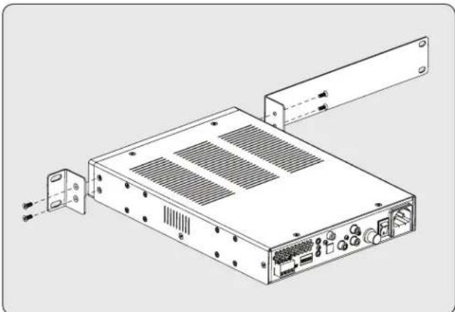
natural_image
Technical line drawing of an electronic device chassis with ports and connectors (no text or symbols)If a dual amplifier installation is desired, an optional MPX500CB Connector Bracket (sold separately) is available. This bracket connector affixes two amplifiers side-by-side, as shown in the following diagram.

natural_image
Isometric line drawing of a two-tiered server or rack unit with ventilation grilles and mounting feet (no text or symbols)1.5 FRONT PANEL (STATUS LIGHTS)
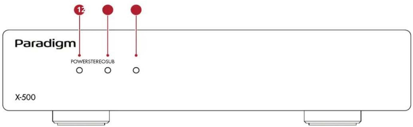
X-500 Front Panel
1 Power:
Blue = Unit is on and ready to play
Red = Unit is in standby or a fault condition has occurred
Off = No AC power/AC power switch turned off
2 STEREO:
Blue = Amplifier playing in Stereo mode
Red = A Fault Condition has occurred
Off = No stereo input signal detected (or amplifier is operating in Subwoofer mode)
3 Sub:
Blue = Amplifier playing in Subwoofer mode
Red = A fault condition has occurred
Off = No subwoofer input signal detected (or amplifier is operating in Stereo mode)
For more information, please refer to sections 6 (Fault Modes) and 7 (Troubleshooting).
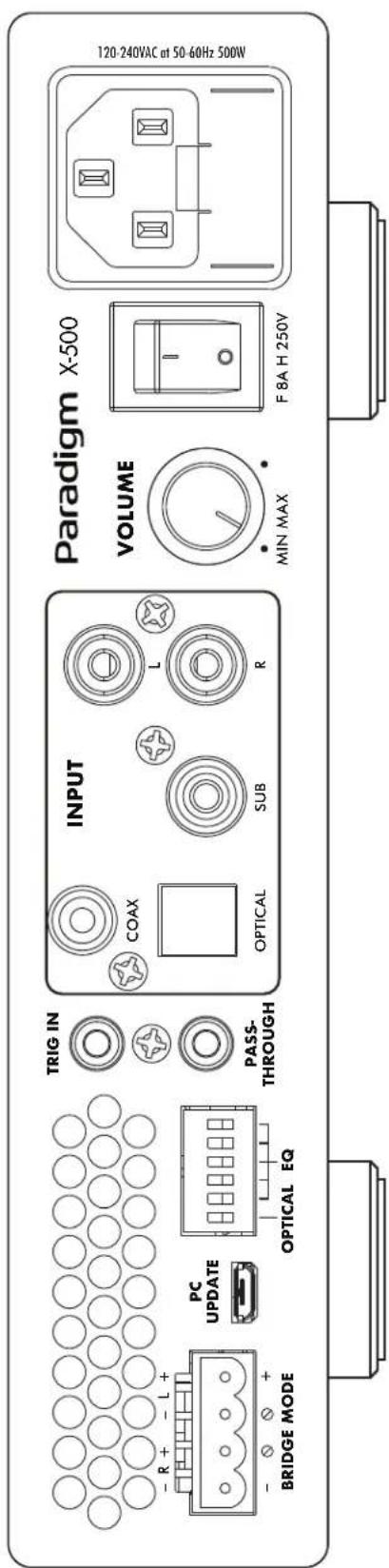
1.6 BACK PANEL
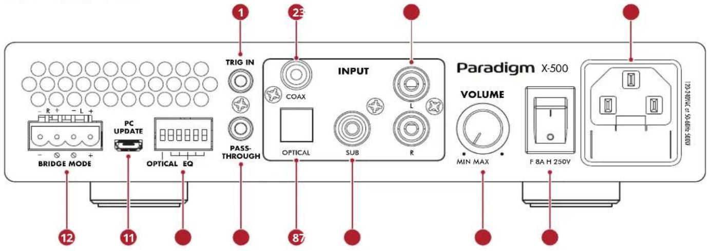
X-500 Back Panel
1 Trigger input
② Coaxial digital audio input
3 Analog RCA stereo inputs
4 Power cord inlet (IEC C18 type)
5 Power: Main power switch ON/OFF
6 Volume: -60dB to 0dB
7 Subwoofer input
8 Optical digital audio input
9 Trigger Pass-through
10 DIP Switches: Digital Input and DSP Preset Selection
11 PC Update (USB) for Firmware Updates
12 Euroblock speaker terminals
For more information, please refer to section 3 (Connections and Back Panel Controls).
1.7 QUICK START
This quick start section includes just enough information to get the X-500 operational. For a deeper understanding of speaker and subwoofer connection options, please review the rest of this manual.
- The X-500 comes out of the box with the shelf/tabletop feet installed. When rack mounting is desired, these feet can be removed using a Phillips screwdriver. The included rack mount ears can be attached using a T10 Torx driver (not included).
2. Speaker Connection(s):
Connect a pair of speakers using a Euroblock (aka Phoenix ^TM ) connector (included) which accepts speaker wire from 28 up to 12 gauge.
a. Pull both sides of the Euroblock connector to remove it from the X-500.
b. Use a small slotted screwdriver to loosen and tighten each contact on the Euroblock when inserting the speaker wire.
c. Follow positive (+) and negative (-) indications shown on the Euroblock connector.
d. After attaching speaker wires to the Euroblock connector, insert it back into the X-500.
3. Subwoofer Connection:
Follow the steps in "Step 2" except use the positive (+) and negative (-) indicators for "Bridge Mode" as shown on the text printed below the Euroblock connector on the X-500 chassis. *Stereo and Bridge mode cannot be used simultaneously*
4. Input Connection(s):
Connect Analog sources using RCA cables. Connect Digital sources using a Digital Coax or Optical cable. When being used to drive a subwoofer, connect the subwoofer out of your source device to the subwoofer input on the X-500.
If using the digital inputs, you must select Coax or Optical using the DIP switch on the back of the X-500 (#10 on the image on page 7).
5. Power Connection:
Insert a power cord into the X-500's AC input. Plug the cord into a wall outlet. Make sure to respect the voltage rating shown beside the AC receptacle.
6. Volume Control:
The X-500 has an onboard volume control if needed. However, typically the X-500 will be used with a source that offers its own volume control (like a streaming device or used with an AV Receiver when driving a subwoofer). In this case the X-500's onboard volume control can effectively be used as a basic volume limiter instead. When being used in this manner, you can set the X-500's volume control to maximum, and then control the overall volume through your source. If audible distortion occurs, turn down the volume control on the X-500 until the sound no longer distorts.
2. CONNECTIONS AND BACK PANEL CONTROLS
2.1 SPEAKER CONNECTIONS

Depending on the level of the input signal, the voltage at the outputs can be high enough to cause electric shock — be sure that power is off when connecting or disconnecting anything. As well, be sure to use speakers rated for use with this X-500 — an overdriven speaker can pose a fire hazard.
X-500 offers options to power either a stereo pair of speakers (or a system like the Paradigm Garden Essentials Outdoor Music System), or a passive subwoofer (custom install subwoofer).
When powering a custom installation subwoofer, the X-500 can be configured in "bridged mode" which combines the output of both amplifier channels in order to provide this speaker with more power.
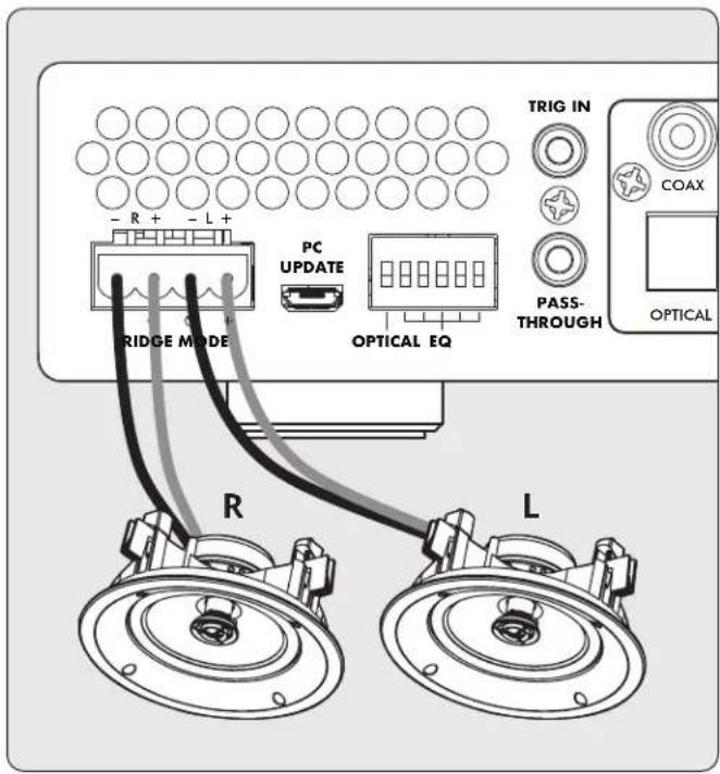
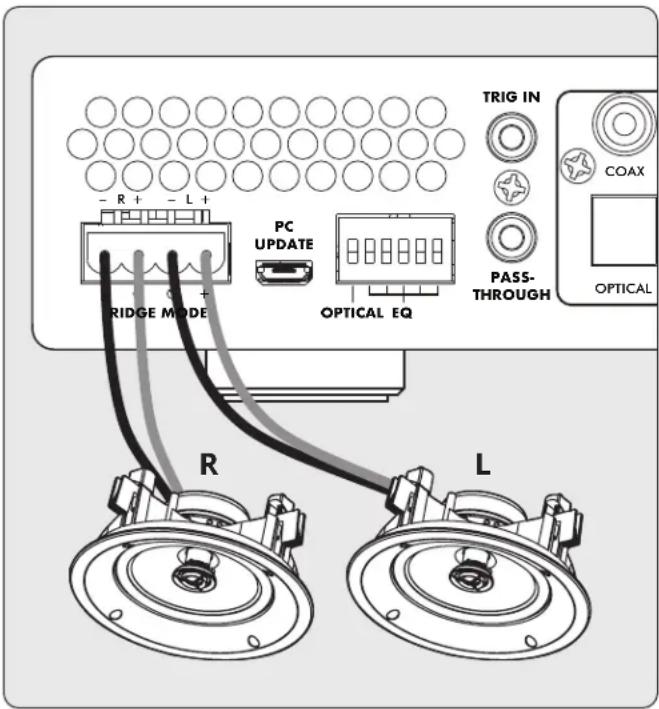
2.2 CONNECTING STEREO SPEAKERS
(or Paradigm Garden Oasis Essentials Outdoor Music System)
Connect a pair of speakers to the X-500 using a Euroblock (also known as a Phoenix ^™ ) connector. These connectors are included with the X-500 and come preinstalled.
Euroblock connectors accept speaker wire up to 12 gauge. Use speakers as low as 4 Ohms in this configuration.
- Remove the Euroblock connector from the X-500 by gently pulling it until it releases.
- Use a small slotted screwdriver to loosen and tighten each contact on the Euroblock when inserting the speaker wire.
-
Connect the red (+) connection on the left speaker to the positive (L+) contact on the Euroblock connector as indicated by the printing located on the X-500 (above the connector) or on the connector itself.
-
Connect the black (-) connection on the left speaker to the negative (L-) contact on the Euroblock connector as indicated by the printing located on the X-500 (above the connector) or on the connector itself.
- Repeat for the right channel.
- After attaching speaker wires to the Euroblock connector, insert it into the X-500 by gently pressing it into place.
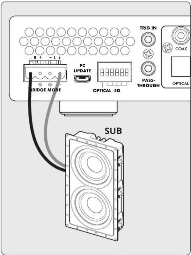
2.3 CONNECTING A PASSIVE (NON-POWERED) SUBWOOFER
This mode only supports subwoofers rated at 8 Ohms or higher. Bridged Mode increases the amplifier power available for a single speaker. This function is designed for passive subwoofers that require external amplification and can be enabled using the below method:
- Remove the Euroblock connector from the X-500 by gently pulling it until it releases.
- Use a small slotted screwdriver to loosen and tighten each contact on the Euroblock when inserting the speaker wire.
- Connect the red (+) connection of the subwoofer to the positive (Bridge +) contact on the Euroblock connector as indicated by the printing located on the X-500 (below the connector).
- Connect the black (-) connection of the subwoofer to the negative (Bridge -) contact on the Euroblock connector as indicated by the printing located on the X-500 (below the connector).
- After attaching subwoofer wires to the Euroblock connector, insert it into the X-500 by gently pressing it into place.

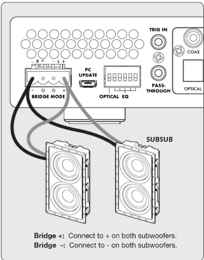
2.4 CONNECTING DUAL DEFIANCE CUSTOM IN-WALL SUBWOOFERS
For maximum performance, Paradigm recommends using an X-500 for each subwoofer in the system. When running 2 sub-woofers from a single amplifier is required, the X-500 can drive dual subs in a “bridged parallel” configuration. Note: This configuration is only recommended with Paradigm Defiance Custom In-Wall subwoofers and you must use the “Dual Subwoofer DSP Preset Profiles” as outlined in the DSP Profile Section.
- Remove the Euroblock connector from the X-500 by gently pulling it until it releases.
- Use a small slotted screwdriver to loosen and tighten each contact on the Euroblock when inserting the speaker wire.
- Connect the red (+) connection of each subwoofer to the positive (Bridge +) contact on the Euroblock connector as indicated by the printing located on the X-500 (below the connector).
- Connect the black (-) connection of each subwoofer to the negative (Bridge -) contact on the Euroblock connector as indicated by the printing located on the X-500 (below the connector).
- After attaching subwoofer wires to the Euroblock connector, insert it into the X-500 by gently pressing it into place.
2.5 DIGITAL INPUT
Stereo digital audio sources can be connected using coaxial or optical cables. The X-500 has one digital optical input, and one digital coaxial input. Both of these inputs support the PCM stereo format (up to 24-bit / 96kHz). If using sources that have an option for selecting between PCM and Bitstream (or Dolby Digital) audio output, select PCM. If the source outputs a non-PCM stream (such as a Dolby or DTS stream), the audio will mute.
Using the DIP switch on the back of the X-500 (See image on Pg. 7) you can select either the Coax or Optical inputs, but only 1 may be used at a time.
2.6 ANALOG INPUTS
Connect stereo analog sources using RCA cables.
2.7 SUBWOOFER INPUT
The X-500 has multiple subwoofer preset configurations to simplify connection to an AV Receiver or AV Preamp (or source component) with a subwoofer output. Connect the subwoofer output of your preamp/processor/source using an RCA cable to either the Analog RCA (R — right), Analog RCA (L — left), or Subwoofer Input. The Analog RCA (R — right), Analog RCA (L — left) inputs will pass through a low-pass filter before being passed to the amplifier. The Subwoofer Input signal is passed directly to the amplifier. If needed, all three RCA inputs can be used simultaneously.
3. DSP PRESETS
The X-500 is loaded with a variety of DSP presets to both improve performance of the speaker, but also to protect it from being overdriven by the amplifier.
DSP preset availability will change over time, and can be updated via the USB connection on the back of the amplifier. For the most up to date list of presets, please refer to the X-500 product page on paradigm.com.
Using the bank of dip switches on the back of the amplifier you may choose from the following DSP preset options:
2.8 POWER
Insert a power cord into the X-500's AC input. Plug the cord into a wall outlet. Ensure that the AC supply matches the voltage rating shown on the back of the X-500.
2.9 TRIGGER CONNECTIONS
The trigger connection allows the X-500 to be turned on or off via the trigger input. When the Trig In 3.5mm (1/8") mini-jack receives power (5–24 volts DC or AC) from an upstream component, the X-500 turns on (Auto-On delay applies). When it stops receiving power, the X-500 turns off immediately. The Trig Out jack allows you to run a cable out to daisy-chain and trigger additional X-500's or another component that uses a trigger in. The trigger out on the X-500 passes through the signal received from the trigger input.
2.10 MASTER POWER SWITCH
This switch is wired directly to the AC mains and turns on and off all power going to the X-500.
2.11 USB CONNECTION
A USB connection is present for updating the DSP presets available on the amplifier. Instructions for updating the DSP presets will be provided with the DSP Update file. This connection can otherwise be ignored.
3.1 DIP Switch Functionality
| Pin1: SPDIF select. Optical/Coaxial |
| Pins 2-5: 16 groups of EQ presets |
| ex: Pins 2-6: 00000=EQ0 |
| ex: Pins 2-6: 10000=EQ16 |
| ex: Pins 2-6: 11111=EQ31 |
3.2 DSP PRESET DIP SWITCH POSITIONS
| Dip Switch Number | ||||||||||
| Preset Number | 2 3 | 4 5 | 6 2, | 3, 4, | 5, 6 | Preset Number | ||||
| Up/Down (U/D) DSP Function Stereo or Sub | ||||||||||
| 0 d d d d | d d, d, d, d, d | flat | stereo* | stereo | ||||||
| 1 d d d d | u d, d, d, d, u 1 | Stylus 170 | stereo | |||||||
| 2 d d d u | d d, d, d, u, d 2 | Stylus 270 | stereo | |||||||
| 3 | d | d | d | u | u | d, d, d, u, u | 3 | Stylus 370 | stereo | |
| 4 | d | d | u | d | d | d, d, u, d, d | 4 | Stylus 470 | stereo | |
| 5 | d | d | u | d | u | d, d, u, d, u | 5 | Garden Oasis Essentials Outdoor Music System | stereo | |
| 6 d d u u | d d, d, u, u, d | 6 | ||||||||
| 7 d d u u | u d, d, u, u, u | 7 | ||||||||
| 8 d u d d | d d, u, d, d, d 8 | Garden Oasis GO4 | ||||||||
| 9 | d | u | d | d | u | d, u, d, d, u | 9 | Garden Oasis GO6 | ||
| 10 | d | u | d | u | d | d, u, d, u, d | 10 | Rock Monitor 60-SM | ||
| 11 | d | u | d | u | u | d, u, d, u, u | 11 | Rock Monitor 80-SM | ||
| 12 | d u | u d | d, u, u, d, d | 12 | ||||||
| 13 | d u | u d | u, u, d, u | 13 | ||||||
| 14 | d u | u u | d, u, u, u, d | 14 | ||||||
| 15 | d u | u u | d, u, u, u, u | 15 | ||||||
| 16 | u d | d d | d u, d, d, d, d | 16 | ||||||
| 17 | u d | d d | u u, d, d, d, u | 17 | ||||||
| 18 | u d | d u | d u, d, d, u, d | 18 | ||||||
| 19 | u d | d u | u u, d, d, u, u | 19 | ||||||
| 20 | u d | u d | d u, d, u, d, d | 20 | ||||||
| 21 | u d | u d | u u, d, u, d, u | 21 | ||||||
| 22 | u d | u u | d u, d, u, u, d | 22 | Garden Oasis SUB 8 (dual voice coil — one voice coil per channel)** | sub | ||||
| 23 | u d | u u | u u, d, u, u, u | 23 | Garden Oasis SUB 8 (each subwoofer's voice coils paralleled into 1 amplifier channel)** | sub | ||||
| 24 | u | u | d | d | d | u, u, d, d, d | 24 | DCS-208FR3 with 80Hz Low-Pass** | sub | |
| 25 | u | u | d | d | u | u, u, d, d, u | 25 | Dual DCS-208FR3 Parallel Bridged with 80Hz Low-Pass** | sub | |
| 26 | u | u | d | u | d | u, u, d, u, d | 26 | DCS-208IW3 Sub with 80Hz Low-Pass** | sub | |
| 27 | u | u | d | u | u | u, u, d, u, u | 27 | Dual DCS-208IW3 Parallel Bridged with 80Hz Low-Pass** | sub | |
| 28 | u | u | u | d | d | u, u, u, d, d | 28 | DCS-208IW3 and BX-208 with 80Hz Low-Pass** | sub | |
| 29 | u u | u d | u u, u, u, d, u | 29 | Dual DCS-208IW3 and BX-208 Parallel Bridged with 80Hz Low-Pass** | sub | ||||
| 30 | u | u | u | u | d | u, u, u, u, d | 30 | Garden Oasis GO10SW with 80Hz Low-Pass** | sub | |
| 31 | u | u | u | u | u | u, u, u, u, u | 31 | Garden Oasis GO12SW with 80Hz Low-Pass** | sub | |
*Output limited to 250W @ 4Ω and 125W @ 8Ω **Low-Pass filters are only implemented on the Left and Right input. The subwoofer input passes all signals.
4. FAULT MODES
4.1 FRONT PANEL POWER LED
| Power LED Status or Fault | |
| Blue On | |
| Red Standby or Fault | |
| Off No AC power | |
4.2 FRONT PANEL ZONE LEDS

| Power LED Stereo LED Subwoofer LED Status or Fault Clear Fault | ||||
| Blue Off — X-500 enabled, no music detected. — | ||||
| Blue Blue — Stereo operation: X-500 enabled, music playing. — | ||||
| Blue — | Off | X-500 enabled, no music detected. — | ||
| Blue — | Blue Subwoofer operation: | X-500 enabled, music playing. — | ||
| Blue Red flashing | — AMP fault. over current / DC Fault. / | Stereo operation. | Self-recovery | |
| Blue Blue flashing | — AMP over temp. Stereo operation. | Self-recovery | ||
| Blue Red | — AMP mute. When AMP temp over upper limit. | Self-recovery | ||
| Red | Red | — Power supply over current. | To clear this fault condition, cycle the power by turning off AC power. Wait 1 minute before turning the X-500 back on. | |
| Blue | — | Red flashing | AMP fault. over current / DC Fault. Subwoofer operation. | Self-recovery |
| Blue | — | Blue flashing | AMP over temp. Subwoofer operation. | Self-recovery |
| Blue — | Red | AMP mute. When AMP temp over upper limit. Subwoofer operation. | Self-recovery | |
| Red | — | Red | Power supply over current. Subwoofer operation. | To clear this fault condition, cycle the power by turning off AC power. Wait 1 minute before turning the X-500 back on. |
| Blue / Red | — | — Software error. Initialization error.(DSP/Codec failure). | To clear this fault condition, cycle the power by turning off AC power. | |
| Red | — | — | Standby | — |
5. FREQUENTLY ASKED QUESTIONS
What is the difference between the stereo analog inputs and the subwoofer input?
The Subwoofer Input
- This input connects to the subwoofer output of an AV processor or AV receiver with bass-management functions as part of its signal routing. It is only active when a subwoofer speaker preset is selected.
The Analog RCA (R - right) and Left (L - left) Inputs
- With a subwoofer speaker preset, the Analog RCA (R — right) and Left (L — left) inputs allow a stereo signal source to drive a subwoofer without the voices or other high-frequency content being heard through the subwoofer. This preset enables the subwoofer to be connected to these inputs even when the signal source contains a full range of information. This preset is ideal when the source equipment does not have built-in bass management.
- With a Stereo Speaker Preset, the full range signals play through the main speakers.
- SPECIFICATIONS
| X-500 | |
| Warranty 3 Years (Parts and Labor) | |
| Channels 2 Channels | |
| Power Output Per Channel(8 Ohm) | 140 Watts |
| Power Output Per Channel(4 Ohm) | 250 Watts |
| High Output Mode (Bridged)Per Channel (8 Ohm) | 500 Watts |
| Frequency Response 20Hz - 20kHz +1/-3dB (when set to preset 0) | |
| Analog Audio Inputs 1 RCA Pair (Left/Right)1 RCA Subwoofer | |
| Digital Audio Inputs 1 Optical1 RCA Coax | |
| 12V Trigger Controls 1 Input 3.5mm1 Pass-Through Connector 3.5mm | |
| Speaker Level Outputs Removable Phoenix ^TM Style (Left/Right) Accommodate Wire Up to 12AWG | |
| Firmware Update Port Micro-USB Connector | |
| Back Panel Controls Main Power Switch (On/Off)Volume Control (Min/Max)Preset Profile Selection (Dip Switches Position 2 Through 6) (32 Presets)Coax or Optical Selection (Dip Switch Position 1) | |
| AC Voltage 120V-240VAC at 50-60Hz | |
| Maximum Power Draw 500 Watts | |
| Standby Power Less than 0.5 Watts | |
| Rack Mount Ears / Feet Included | |
| Rack Space (feet removed) 1U Height x 1/2 Width | |
| Dimensions (H x W x D, with feet,no rack mount ears) | 2.17" x 8.5" x 12.5" (5.5 x 21.6 x 31.8 cm) |
| Weight | 7.22 lb (3.28kg) |
7. LIMITED WARRANTY
IMPORTANT! The amplifiers covered by this manual is designed for use with matching Paradigm® and Paradigm® Reference in-wall/in-ceiling subwoofers only. Use with any other brand of subwoofer can cause permanent damage and will void the Paradigm warranty.
Paradigm ^® and Paradigm ^® Reference amplifiers are warranted to be and remain free of manufacturing and/or material defects for a period of three (3) years from the date of the original retail purchase. Within this specified period, repair, replacement or adjustment of parts for manufacturing and/or material defects will be free of charge. Thermal or mechanical abuse/ misuse is not covered under warranty.
Limitations:
- Warranty begins on date of original retail purchase from an Authorized Paradigm® or Paradigm® Reference Dealer only. It is not transferable;
- Warranty applies to product in normal home use only. If the product is subjected to any of the conditions outlined in the next section, warranty is void;
- Warranty does not apply if the product is used in professional or commercial applications.
Warranty is Void if:
- The product has been abused (intentionally or accidentally);
- The product has been used in conjunction with unsuitable or faulty equipment;
- The product has been subjected to damaging signals, derangement in transport, mechanical damage or any abnormal conditions;
- The product has been tampered with or damaged by an unauthorized service facility;
- The serial number has been removed or defaced.
Owner Responsibilities:
- Provide normal/reasonable operating care and maintenance;
- Provide or pay for transportation charges for product to service facility;
- Provide proof of purchase (your sales receipt given at time of purchase from your Authorized Paradigm® Reference Dealer).
Should servicing be required, contact your nearest Authorized Paradigm® or Paradigm® Reference Dealer, Paradigm Electronics Inc., or Import Distributor (outside the U.S. and Canada) to arrange, bring in or ship prepaid any defective unit. Visit our website at paradigm.com for more information.
Paradigm Electronics Inc. reserves the right to improve the design of any product without assuming any obligation to modify any product previously manufactured.
This warranty is in lieu of all other warranties expressed or implied, of merchantability, fitness for any particular purpose and may not be extended or enlarged by anyone. In no event shall Paradigm Electronics Inc., their agents, or representatives be responsible for any incidental or consequential damages. Some jurisdictions do not allow limitation of incidental or consequential damages, so this exclusion may not apply to you.
Retain this manual and your sales receipt for proof of warranty term and proof of purchase.
8. THE BIG PICTURE: X-500


NOTES
NOTES
Paradigm®

NE PAS LOCALISER DANS LES ENDROITS SUIVANTS :
natural_image
Technical line drawing of an electronic device chassis with ports and connectors (no text or symbols)natural_image
Isometric line drawing of a dual-chamber electronic device with ventilation grilles and mounting feet (no text or symbols)1.5 PANNEAU FRONTAL (STATUT DES LUMIÈRES)

Panneau frontal du X-500
1 Alimentation :
2.3 CONNEXION D'UN SUBWOOFER PASSIF (NON ALIMENTÉ)
2.4 CONNEXION DE DEUX SUBWOOFER ENCASTRES DEFIANCE CUSTOM
REMARQUES
Paradigm®
paradigm.com
©2022 Paradigm Electronics Inc. All rights reserved. rev.4 012422
- CAUTION
- IMPORTANT SAFETY INSTRUCTIONS
- DO NOT LOCATE IN THE FOLLOWING PLACES:
- NOTES ON ENVIRONMENTAL PROTECTION
- RECYCLING AND REUSE GUIDELINES (Europe)
- TABLE OF CONTENTS
- Introduction and Quick Start .... 5
- Connections and Back Panel Controls ..... 9
- DSP Presets....11
- Fault Modes ..... 13
- Frequently Asked Questions .... 14
- Specifications 15
- Limited Warranty 16
- The Big Picture: X-500 ..... 17
- INTRODUCTION AND QUICK START
- BEFORE MAKING CONNECTIONS
- BOX CONTENTS
- IN-USE NOTICES
- RACK AND SHELF MOUNTING
- FRONT PANEL (STATUS LIGHTS)
- X-500 Front Panel
- Power:
- STEREO:
- Sub:
- QUICK START
- Speaker Connection(s):
- Subwoofer Connection:
- Input Connection(s):
- Power Connection:
- Volume Control:
- CONNECTIONS AND BACK PANEL CONTROLS
- SPEAKER CONNECTIONS
- CONNECTING STEREO SPEAKERS
- CONNECTING A PASSIVE (NON-POWERED) SUBWOOFER
- CONNECTING DUAL DEFIANCE CUSTOM IN-WALL SUBWOOFERS
- DIGITAL INPUT
- ANALOG INPUTS
- SUBWOOFER INPUT
- DSP PRESETS
- POWER
- TRIGGER CONNECTIONS
- MASTER POWER SWITCH
- USB CONNECTION
- DIP Switch Functionality
- FAULT MODES
- FRONT PANEL POWER LED
- FRONT PANEL ZONE LEDS
- FREQUENTLY ASKED QUESTIONS
- The Subwoofer Input
- The Analog RCA (R - right) and Left (L - left) Inputs
- LIMITED WARRANTY
- Limitations:
- Warranty is Void if:
- Owner Responsibilities:
- THE BIG PICTURE: X-500
- NOTES
- Paradigm®
- NE PAS LOCALISER DANS LES ENDROITS SUIVANTS :
- PANNEAU FRONTAL (STATUT DES LUMIÈRES)
- Panneau frontal du X-500
- Alimentation :
- CONNEXION D'UN SUBWOOFER PASSIF (NON ALIMENTÉ)
- CONNEXION DE DEUX SUBWOOFER ENCASTRES DEFIANCE CUSTOM
- REMARQUES
Brand : Paradigm
Model : X500
Category : Receiver