
APSX1250 - Inverter Tripp Lite - Free user manual and instructions
Find the device manual for free APSX1250 Tripp Lite in PDF.

| Product type | DC-to-AC inverter/charger |
| Brand | Tripp Lite |
| Model | APSX1250 |
| DC input voltage | 12 VDC |
| AC output voltage | 230 VAC, 50 Hz |
| Continuous power | 1250 W |
| Peak power (DoubleBoost) | Up to 200% of rated power for 10 seconds |
| OverPower power | Up to 150% of rated power for 1 hour |
| Battery charger | 3-stage (bulk, absorption, float), high current |
| Compatible battery type | Gel, AGM, flooded (adjustable via DIP switch) |
| Built-in protections | Surge protection (ISOBAR®), overload, overheat, reverse polarity, excessive discharge |
| Connectivity | Port for optional remote (APSRM4) |
| Cooling | Silent fan |
| Mounting | Horizontal or wall (control panel to the side) |
| Indicators | LED Line, Invert, Charging, Battery voltage |
| Configuration | Adjustable DIP switches (battery type, transfer voltage, etc.) |
| Moisture resistance | Yes (non-immersible) |
| Warranty | 2 years |
| Maintenance | No user-serviceable parts; keep dry |
Frequently Asked Questions - APSX1250 Tripp Lite
User questions about APSX1250 Tripp Lite
0 question about this device. Answer the ones you know or ask your own.
Ask a new question about this device
Download the instructions for your Inverter in PDF format for free! Find your manual APSX1250 - Tripp Lite and take your electronic device back in hand. On this page are published all the documents necessary for the use of your device. APSX1250 by Tripp Lite.
USER MANUAL APSX1250 Tripp Lite
DC-to-AC Inverter/Chargers
APSX Models Input Output
Invert: 12 VDC 230V, 50 Hz. AC
Charge: 230V, 50 Hz. AC 12 VDC
APS Models Input
Invert:
12 VDC
Charge:
Output
120V, 60 Hz. AC
120V, 60 Hz. AC

Quiet Mobile Power
Congratulations! You've purchased the most advanced, feature-rich Inverter/Charger designed as an alternative energy source for residential, commercial or recreational vehicle applications. Tripp Lite Inverter/Chargers are the quiet alternative to gas generators—with no fumes, fuel or noise to deal with! You get AC electricity anywhere and anytime you need it: utility power disruptions, rolling down the highway, dry camping in majestic back country or parked overnight at a money-saving non-electric site. Inverter/Chargers provide your equipment with utility- or generator-supplied AC electricity (filtered through premium ISOBAR® surge protection) whenever available. In addition, your Inverter/Charger automatically recharges your connected battery bank. Whenever blackouts, brownouts or high voltages occur, your Inverter/Charger immediately and automatically switches to battery power.
Better for
Your Equipment
Premium Protection Levels
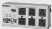
• Built-In ISOBAR® Surge Protection
• Automatic Overload Protection
Ideal Output for All Loads
• Frequency-Controlled Output
• Automatic Load Switching
• Balanced Load Sharing
Better for
Your Batteries
Faster Battery Recharge
• High-Amp, 3-Stage Battery Charger
Critical Battery Protection
• High-Efficiency DC-to-AC Inversion
Better for
You
Quiet, Simple, Maintenance-Free Operation
- Multi-Function Lights & Switches
- Moisture-Resistant Construction*
* Inverter/Chargers are moisture-resistant, not waterproof.
Safety 2
Feature Identification 3
Operation 4-5
Configuration 5-6
Battery Selection 7
Mounting 8
Battery Connection 9
AC Input/Output Connection 10
Service/Maintenance 10
Troubleshooting 11
Warranty 12
Español 13
Français 25
Русский 37
WARRANTY REGISTRATION
Register your product today and be automatically entered to win an ISOBAR surge protector in our monthly drawing!
www.tripplite.com/warranty


text_image
TRIPP·LITE
Manufacturing Excellence.
1111 W. 35th Street, Chicago, IL 60609 USA • www.tripplite.com/support
Copyright © 2019 Tripp Lite. All rights reserved. PowerVerter® is a registered trademark of Tripp Lite.
SAVE THESE INSTRUCTIONS!
This manual contains important instructions and warnings that should be followed during the installation, operation and storage of this product.
Location Warnings
- Although your Inverter/Charger is moisture resistant, it is NOT waterproof. Flooding the unit with water will cause it to short circuit and could cause personal injury due to electric shock. Never immerse the unit, and avoid any area where standing water might accumulate. Mounting should be in the driest location available.
- Leave a minimum of 2" clearance at front and back of the Inverter/Charger for proper ventilation. To avoid automatic Inverter/Charger shutdown due to overtemperature, any compartment that contains the Inverter/Charger must be properly ventilated with adequate outside air flow. The heavier the load of connected equipment, the more heat will be generated by the unit.
- Do not install the Inverter/Charger directly near magnetic storage media, as this may result in data corruption.
- Do not install near flammable materials, fuel or chemicals.
- Do not mount unit with its front or rear panel facing down (at any angle). Mounting in this manner will seriously inhibit the unit's internal cooling, eventually causing product damage not covered under warranty.
Battery Connection Warnings
- The battery should be connected before operating the Inverter/Charger
- Multiple battery systems must be comprised of batteries of identical voltage, age, amp-hour capacity and type.
- Because explosive hydrogen gas can accumulate near batteries if they are not kept well ventilated, your batteries should not be installed (whether for a mobile or stationary application) in a “dead air” compartment. Ideally, any compartment would have some ventilation to outside air.
- Sparks may result during final battery connection. Always observe proper polarity as batteries are connected.
- Do not allow objects to contact the two DC input terminals. Do not short or bridge these terminals together. Serious personal injury or property damage could result.
Equipment Connection Warnings
Use of this equipment in life support applications where failure of this equipment can reasonably be expected to cause the failure of the life support equipment or to significantly affect its safety or effectiveness is not recommended. Do not use this equipment in the presence of a flammable anesthetic mixture with air, oxygen or nitrous oxide.
- You may experience uneven performance results if you connect a surge suppressor, line conditioner or UPS system to the output of the Inverter/Charger.
- Corded Models: Do not modify the Inverter/Charger's plug or receptacle in a way that eliminates its ground connection. Do not use power adapters that will eliminate the plug's ground connection.
- Connect your Inverter/Charger only to a properly grounded AC power outlet or hardwired source. Do not plug the unit into itself; this will damage the device and void your warranty.
- The main grounding lug should be connected to earth ground or to the vehicle chassis with a minimum 8 AWG wire.
Operation Warnings
- Your Inverter/Charger does not require routine maintenance. Do not open the device for any reason. There are no user-serviceable parts inside.
- Potentially lethal voltages exist within the Inverter/Charger as long as the battery supply and/or AC input are connected. During any service work, the battery supply and AC input connection (if any) should therefore be disconnected.
- Do not connect or disconnect batteries while the Inverter/Charger is operating in either inverting or charging mode. Operating Mode Switch should be in the DC OFF position. Dangerous arcing may result.

Caution: These models have a failsafe AC pass-through feature where the AC output will be live (if AC input is available) even though the operating mode switch is set to "DC OFF."
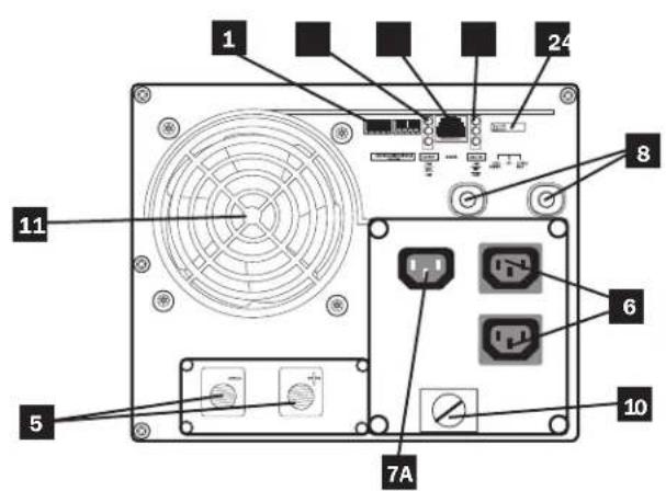
Feature Identification
Identify the premium features on your specific model and quickly locate instructions on how to maximize their use.
1 Configuration DIP Switches: optimize Inverter/Charger operation depending on your application. See Configuration section for setting instructions.
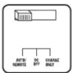
2 Operating Mode Switch: controls Inverter/Charger operation. The "AUTO/REMOTE" setting ensures your equipment receives constant, uninterrupted AC power. It also enables the Inverter/Charger to be remotely monitored and controlled with an optional remote module (Tripp Lite model APSRM4, sold separately). The "CHARGE ONLY" setting allows your batteries to return to full charge faster by turning the inverter off which halts battery discharging. The "DC OFF" setting de-energizes the unit and connects AC OUT to AC IN. See Operation section for setting instructions.
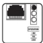
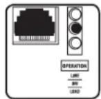
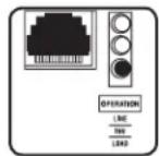
3 "LINE", "INVERT", "LOAD" LEDs: show whether the Inverter/Charger is operating from AC line power or DC battery power. It also warns you if the connected equipment load is too high. See Operation section for instructions on reading the indicator lights.
4 "BATT VOLTAGE" LEDs: these three lights will turn ON in several sequences to show approximate battery level. See Operation section for instructions on reading the indicator lights.
5 DC Power Terminals: connect to your battery terminals. See Battery Connection section for instructions.
6 AC Output Receptacles
7A AC Input Receptacle (230V Models): attach input cord to connect the Inverter/Charger to any source of utility- or generator-supplied AC power. The user must provide an appropriate country-specific input cable for 230V Models. See AC Input/Output Connection section for instructions.
7B AC Input Cord (120V Models): plug the Inverter/Charger into a utility- or generator-supplied AC power outlet.
8 Resettable Circuit Breakers: protect your Inverter/Charger against damage due to overload or charger failure. See Operation section for resetting instructions.
9 Remote Control Module Connector: allows remote monitoring and control with an optional module (Tripp Lite model APSRM4, sold separately). See remote module owner's manual for connection instructions.
10 Main Ground Lug: properly grounds the Inverter/Charger to vehicle grounding system or to earth ground. See Configuration section for instructions.
11 Cooling Fan: quiet, efficient fan prolongs equipment service life.
text_image
1 24 8 6 7A 10 5 11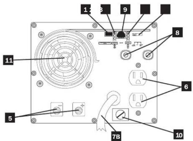
text_image
1 2 3 9 8 11 5 6 7B 10Front View (230V Non-Corded Models) Front View (120V Corded Models)
Operation
Switch Modes
After configuring, mounting and connecting your Inverter/Charger, you are able to operate it by switching between the following operating modes as appropriate to your situation:
"AUTO/REMOTE": Switch to this mode when you need constant, uninterrupted AC power for connected appliances and equipment. The Inverter/Charger will continue to supply AC power to connected equipment and to charge your connected batteries while utility- or generator-supplied AC power is present. Since the inverter is ON (but in Standby) in this mode, it will auto switch to your battery system to supply AC power to co equipment in the absence of a utility/generator source under voltage situations. "AUTO/REMOTE" also enables remote control module (Tripp Lite model APSRM4, sold function when connected to the unit.
"CHARGE ONLY": Switch to this mode when you are not using connected appliances and equipment in order to conserve battery power by disabling the inverter. The Inverter/Charger will continue to supply AC power to connected equipment and charge connected batteries while utility- or generator-supplied AC power is. However, since the inverter is OFF in this mode, it WILL AC power to connected equipment in the absence of a generator source or in over/under voltage situations.
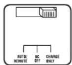
"DC OFF": Switch to this mode to prevent the inverter from drawing power from the batteries. Use this switch to automatically reset the unit if it shuts down due to overload or overheating. First remove the excessive load or allow the unit to sufficiently cool (applicable to your situation). Switch to "DC OFF", then back to "AUTO/REMOTE" or "CHARGE ONLY" as desired. If unit f remove more load or allow unit to cool further and retry optional remote control module (Tripp Lite model APSR separately) to reset unit due to overload and overtempo
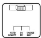
CAUTION: The unit will always pass AC power through to connected equipment if plugged into a live AC outlet, regardless of the position of the Operating Mode Switch.
Indicator Lights
Your Inverter/Charger is equipped with a simple, intuitive, user-friendly set of indicator lights. These easily-remembered “traffic light” signals will allow you, shortly after first use, to tell at a glance a wide variety of operating details.
"LINE Green LED": If the operating mode switch is set to "AUTO/REMOTE", this light will ILLUMINATE CONTINUOUSLY when your connected equipment is receiving continuous AC power supplied from a utility/generator source.
If the operating mode switch is set to "CHARGE ONLY", this light will BLINK to alert you that the unit's inverter is OFF and will NOT supply AC power in the absence of a utility/generator source or in over/under voltage situations.
Indicator Lights (Continued)
"INV" (Inverting) Yellow LED: This light will ILLUMINATE CONTINUOUSLY whenever connected equipment is receiving battery-supplied, inverted AC power (in the absence of a utility/generator source or in over/under voltage situations). This light will be off when AC power is supplying the load.
"LOAD" Red LED: This red light will ILLUMINATE CONTINUOUSLY whenever the inverter is functioning and the power demanded by connected appliances and equipment exceeds 100% of load capacity. The light will BLINK to alert you when the inverter shuts down due to a severe overload or overheating. If this happens, turn the operating mode switch to "DC OFF"; remove the overload and let the unit cool. You may then turn the operating mode switch to either "AUTO/REMOTE" or "CHARGE ONLY" after it has adequately cooled. This light will be off when AC power is supplying the load.
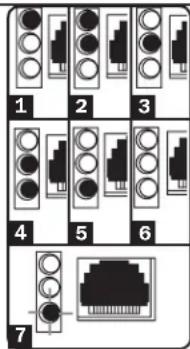
"BATT VOLTAGE" LEDs: If the operating mode switch is in the "AUTO/REMOTE" or "CHARGE ONLY" position, the LEDs indicate the approximate charge level and voltage of your connected battery bank and alert you to several fault conditions. See Chart for charge and voltage levels.
LED Function with Switch in "AUTO/REMOTE" or "Charge Only" Position
Approximate Battery Charge Level*
LEDs Battery Capacity
Illuminated (Charging/Discharging)
1 Green 91%–Full
2 Green & Yellow 81%–90%
3 Yellow 61%-80%
4 Yellow & Red 41%–60%
5 Red 21%-40%
6 All three lights off 1%–20%
7 Flashing red 0% (Inverter shutdown)**
* Charge levels listed are approximate. Actual conditions vary depending on battery condition and load. ** Inverter shutdown protects battery against damage due to excessive discharge.
Fault Condition
| LEDs | Fault | |
| Illuminated | Condition | |
| 1 | All three lights flash slowly* | Excessive discharge (Inverter shutdown) |
| 2 | All three lights flash quickly** | Overcharge (Charger shutdown) |
text_image
1 2 3 4 5 6 7*Approximately 12 second on, 32 second off. See Troubleshooting section. Inverter shutdown protects battery against damage due to excessive discharge.** Approximately 14 second on, 14 second off. Charger shutdown protects battery against damage due to overcharge. May also indicate a battery charger fault exists. See Troubleshooting section.
Operation
Resetting Your Inverter/Charger to Restore AC Power
Your Inverter/Charger may cease supplying AC power or DC charging power in order to protect itself from overload or to protect your electrical system. To restore normal functioning:
Overload Reset: Switch operating mode switch to "DC OFF" and remove some of the connected electrical load (i.e., turn off some of the AC devices drawing power which may have caused the overload of the unit). Wait one minute, then switch operating mode switch back to either "AUTO/REMOTE" or "CHARGE ONLY."
Output Circuit Breaker Reset: If tripped, remove a portion of the load, wait one minute and then press breaker button to reset.
Configuration
Set Configuration DIP Switches
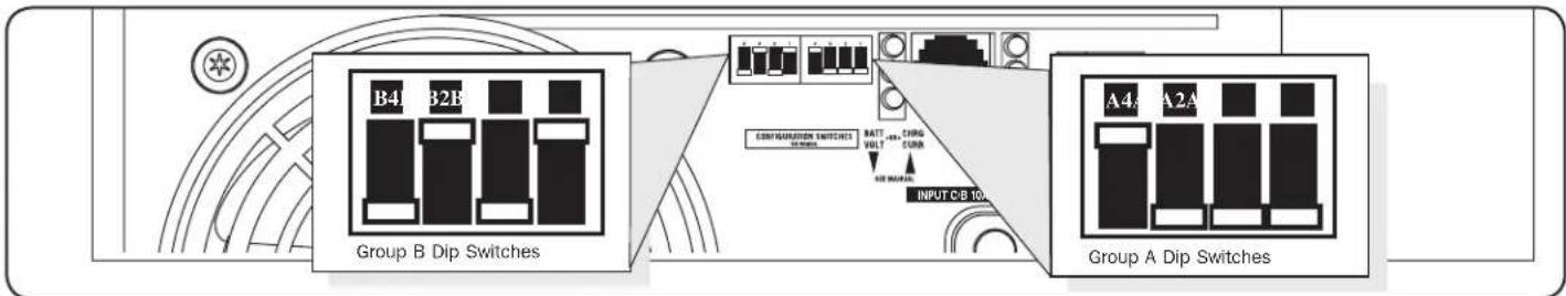
Using a small tool, set the Configuration DIP Switches (located on the front panel, see diagram) to optimize Inverter/Charger operation depending on your application. Refer to the appropriate section to review the instructions for your specific model.
text_image
B4 B2B Group B Dip Switches BATT CHNG VOLT CUB AIR WIND INPUT C/B 10A A4 A2A Group A Dip SwitchesGroup A DIP Switches (All Models)
Using a small tool, configure your Inverter/Charger by setting the four Group A DIP Switches (located on the front panel of your unit; see diagram) as follows:
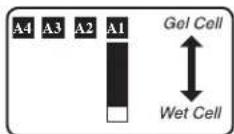
A1 Select Battery Type—REQUIRED
CAUTION: The Battery Type DIP Switch setting must match the type of batteries you connect, or your batteries may be degraded or damaged over an extended period of time. See "Battery Selection" section for more information.
Battery Type Switch Position
AGM/Gel Cell (Sealed) Battery Up
Wet Cell (Vented) Battery Down (factory setting)
A2 Select Charger Enable/Inhibit
Switch is preset to ENABLE, which permits continuous battery charging. If you are connecting your unit to batteries with a separate charger, you may set this switch to INHIBIT to disable its built-in charger to prevent overcharging.
Battery Type Switch Position
Inhibit Up
Enable Down (factory setting)

A4 A3 Select Low AC Input Voltage Point for Switching to Battery—OPTIONAL\*
Voltage and Level
| 120V Models | 230V Models | Switch Position |
| A 105V | 201V | A4 Up & A3 Up |
| B 95V | 182V | A4 Up & A3 Down |
| C 85V | 163V | A4 Down & A3 Up |
| D 75V | 144V | A4 Down & A3 Down (factory setting) |
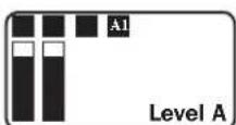
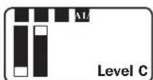
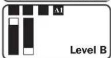
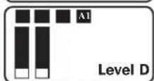
* Most of your connected appliances and equipment will perform adequately when your Inverter/Charger's Low AC Voltage Input Point (DIP Switch #3 and #4 of Group A) are set to Level B (95V for 120V Models/182V for 230V Models). However, if the unit frequently switches to battery power due to momentary low line voltage swings that would have little effect on equipment operation, you may wish to adjust this setting. By decreasing the Low AC Voltage Input Point, you will reduce the number of times that your unit switches to battery due to voltage swings.
Configuration
Group B DIP Switches (Select Models Only)
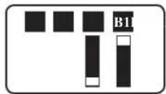
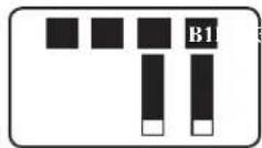
B1 B2 Select AC Input Current Sharing—OPTIONAL
Your Inverter/Charger features a high-output battery charger that can draw a significant amount of AC power from your utility source or generator when charging at its maximum rate. If your unit is supplying its full AC power rating to its connected heavy electrical loads at the same time as this high charging occurs, the AC input circuit breaker could trip, resulting in the complete shut off of pass-though utility power.
To reduce the chance of tripping this breaker, all Inverter/Chargers are pre-set to automatically limit the input current as described in "Most Limiting" below. If your unit is equipped with DIP switches B2 and B1, they may be used to select other AC input current sharing settings. Verify that AC input wiring is rated for the higher current that results when using the other settings.
Select Battery Charger-Limiting Points
"Most Limiting" (B2 & B1 Up): Charger-limiting takes effect the moment any AC load is applied; charger output falls gradually from full output at no AC load passing through to no output at full load (factory setting).
"Less Limiting" (B2 Up & B1 Down): Charger-limiting begins when the Inverter/Charger's load reaches 33% of the Inverter/Charger's load rating. Charger output falls gradually from full output at 33% of the Inverter/Charger's load rating to about 33% of full output at full load.
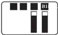
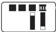
"Least Limiting" (B2 Down & B1 Up): Charger-limiting begins when the Inverter/Charger's load reaches 66% of the Inverter/Charger's load rating. Charger output falls gradually from full output at 66% of the Inverter/Charger's load rating to about 66% of full output at full load.
"No Limiting" (B2 & B1 Down): No charger-limiting occurs at any load size.
B3 Select Equalize Battery Charge—OPTIONAL
This DIP Switch is momentarily engaged to begin the process of equalizing the charge state of your battery's cells by time-limited overcharge of all cells. This can extend the useful life of certain types of batteries; consult with your battery's manufacturer to determine if your batteries could benefit from this process. The charge equalization process is automatic; once started, it can only be stopped by removing the input power.
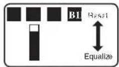
Setting Procedure
- Move to "Equalize" (DOWN) position for three seconds.
- Move to "Reset" (UP) position and leave it there. This is the factory default setting.
CAUTION: Do not leave DIP switch B3 in the down position after beginning process. Battery charge equalization should only be performed in strict accordance with the battery manufacturer's instructions and specifications.
Battery Charge Switch Position
Reset Up (factory setting)
Equalize Down—momentarily
B4 Set Battery Charging Amps—OPTIONAL
Check the nameplate label for your unit's high- and low-charging amp options. By setting on high charging, your batteries will charge at maximum speed. When setting on low charging, you lengthen the life of your batteries (especially smaller ones).
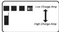
Battery Charger Switch Position
Low Charge Amps Up (factory setting)
High Charge Amps Down
CAUTION: When switching to the High Charge Amp setting, the user must ensure that the amp-hour capacity of their battery system exceeds the amperage of the High Charge Amp setting or the batteries may be damaged or degraded.
Connect Remote Control—OPTIONAL
All models feature an 8-conductor telephone style receptacle on the front panel for use with an optional remote control module (Tripp Lite model APSRM, sold separately). The remote module allows the Inverter/Charger to be mounted in a compartment or cabinet out of sight, while operated conveniently from the remote control module. See instructions packed with the remote control module.
Battery Selection
Select Auxiliary Battery Type (if any)
Select “Deep Cycle” batteries to receive optimum performance from your Inverter/Charger. Do not use ordinary car or starting batteries or batteries rated in Cold Cranking Amps (CCA). If the batteries you connect to the Inverter/Charger are not true Deep Cycle batteries, their operational lifetimes may be significantly shortened. If you are using the same battery bank to power the Inverter/Charger as well as DC loads, your battery bank will need to be appropriately sized (larger loads will require a battery bank with a larger amp-hour capacity) or the operational lifetimes of the batteries may be significantly shortened.
Batteries of either Wet-Cell (vented) or Gel-Cell /Absorbed Glass Mat (sealed) construction are ideal. 6-volt "golf cart", Marine Deep-Cycle or 8D Deep-Cycle batteries are also acceptable. You must set the Inverter/Charger's Battery Type DIP Switch (see Configuration section for more information) to match the type of batteries you connect or your batteries may be degraded or damaged over an extended period of time. In many cases, the vehicle battery may be the only one installed. Auxiliary batteries must be identical to the vehicle batteries if they are connected to each other.
Match Battery Amp-Hour Capacity to Your Application
Select a battery or system of batteries that will provide your Inverter/Charger with proper DC voltage and an adequate amp-hour capacity to power your application. Even though Tripp Lite Inverter/Chargers are highly-efficient at DC-to-AC inversion, their rated output capacities are limited by the total amp-hour capacity of connected batteries and the support of your vehicle's alternator if the engine is kept running.
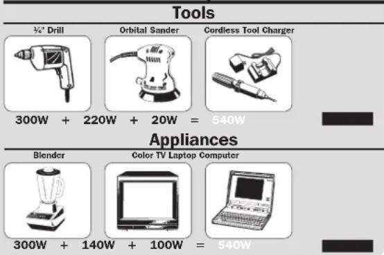
- STEP 1: Determine Total Wattage Required
Add the wattage ratings of all equipment you will connect to your Inverter/Charger. Wattage ratings are usually listed in equipment manuals or on nameplates. If your equipment is rated in amps, multiply that number times AC utility voltage to determine watts. (Example: a 14 in. drill requires 212 amps. 212 amps × 120 volts = 300 watts.)
Note: Your Inverter/Charger will operate at higher efficiencies at about 75% - 80% of nameplate rating.
Example
text_image
Tools 300W + 220W + 20W = 540W Appliances Blender Color TV Laptop Computer 300W + 140W + 100W = 540W- STEP 2: Determine DC Battery Amps Required
Divide the total wattage required (from step 1, above) by the battery voltage (12) to determine the DC amps required.
$$ 5 4 0 \text { watts } \div 1 2 \mathrm{V} = 4 5 \text { DC Amps } $$
• STEP 3: Estimate Battery Amp-Hours Required
(for operation unsupported by the alternator)
Multiply the DC amps required (from step 2, above) by the number of hours you estimate you will operate your equipment exclusively from battery power before you have to recharge your batteries with utility- or generator-supplied AC power. Compensate for inefficiency by multiplying this number by 1.2. This will give you a rough estimate of how many amp-hours of battery power (from one or several batteries) you should connect to your Inverter/Charger.
45 DC Amps × 5 Hrs. Runtime
× 1.2 Inefficiency Rating = 270 Amp-Hours
NOTE! Battery amp-hour ratings are usually given for a 20-hour discharge rate. Actual amp-hour capacities are less when batteries are discharged at faster rates. For example, batteries discharged in 55 minutes provide only 50% of their listed amp-hour ratings, while batteries discharged in 9 minutes provide as little as 30% of their amp-hour ratings.
- STEP 4: Estimate Battery Recharge Required, Given Your Application
You must allow your batteries to recharge long enough to replace the charge lost during inverter operation or else you will eventually run down your batteries. To estimate the minimum amount of time you need to recharge your batteries given your application, divide your required battery amp-hours (from step 3, above) by your Inverter/Charger's rated charging amps.
270 Amp-Hours ÷ 55 Amps
Inverter/Charger Rating = 5 Hours Recharge
NOTE! For Tripp Lite Inverter/Chargers providing 1250 watts or less of continuous AC power, a full-size battery will normally allow sufficient power for many applications before recharging is necessary. For mobile applications, if a single battery is continuously fed by an alternator at high idle or faster, then recharging from utility or generator power may not be necessary. For Tripp Lite Inverter/Chargers over 1250 watts used in mobile applications, Tripp Lite recommends you use at least two batteries, if possible fed by a heavy-duty alternator anytime the vehicle is running. Tripp Lite Inverter/Chargers will provide adequate power for ordinary usage within limited times without the assistance of utility or generator power. However, when operating extremely heavy electrical loads at their peak in the absence of utility power, you may wish to “assist your batteries” by running an auxiliary generator or vehicle engine, and doing so at faster than normal idling.
Mounting

WARNING!
Mount your Inverter/Charger BEFORE DC battery and AC power connection. Failure to follow these instructions may lead to personal injury and/or damage to the Inverter/Charger and connected systems.
Tripp Lite manufactures a variety of different Inverter/Chargers with a variety of different mounting options for use in vehicular or non-vehicular applications. Tripp Lite recommends permanent mounting of your Inverter/Charger in any of the configurations illustrated below. User must supply mounting hardware and is responsible for determining if the hardware and mounting surface are suitable to support the weight of the Inverter/Charger. Contact Tripp Lite if you require further assistance in mounting your Inverter/Charger.
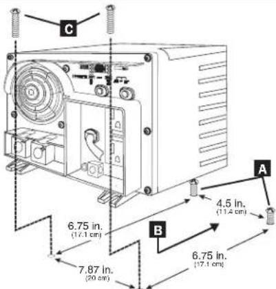
Horizontal Mount
A Using the measurements from the diagram, install two user-supplied 14 " (6 mm) fasteners into a rigid horizontal surface, leaving the heads slightly raised. B Slide the Inverter/Charger back over the fasteners to engage the mounting slots molded on the bottom of the Inverter/Charger cabinet. C Install and tighten two user-supplied 14 " (6 mm) fasteners into the mounting feet molded on the front of the Inverter/Charger cabinet.
text_image
C 6.75 in. (17.1 cm) 7.87 in. (20 cm) B 4.5 in. (17.4 cm) 6.75 in. (17.1 cm)The polycarbonate cabinet and mounting feet of your Inverter/Charger are durable enough to allow for wall mounting as well (if your vehicle compartment requires this configuration). For wall mounting, the control panel of the Inverter/Charger must face to the side and not up or down. Allow 2" (50 mm) minimum front and rear clearance for adequate ventilation.
Battery Connection
Connect your Inverter/Charger to your batteries using the following procedures:
- Connect DC Wiring: Though your Inverter/Charger is a high-efficiency converter of electricity, its rated output capacity is limited by the length and gauge of the cabling running from the battery to the unit. Use the shortest length and largest diameter cabling (maximum 2/0 gauge) to fit your Inverter/Charger's DC Input terminals. Shorter and heavier gauge cabling reduces DC voltage drop and allows for maximum transfer of current. Your Inverter/Charger is capable of delivering peak wattage at up to 200% of its rated continuous wattage output for brief periods of time. Heavier gauge cabling should be used when
continuously operating heavy draw equipment under these conditions. Tighten your Inverter/Charger and battery terminals to approximately 3.5 Newton-meters of torque to create an efficient connection and to prevent excessive heating at this connection. Insufficient tightening of the terminals could void your warranty.
- Connect Ground: Using a 8 AWG (3.15 mm) wire or larger directly connect the Main Ground Lug to the vehicle's chassis or earth ground. See the Feature Identification section to locate the Main Ground Lug on your specific Inverter/Charger model. All installations must comply with national and local codes and ordinances.
- Connect Fuse: NEC (National Electrical Code) article 551 requires that you connect your Inverter/Charger's positive DC Terminal directly to a UL-listed fuse(s) and fuse block(s) within 18 inches (450 mm) of the battery. The fuse's rating must equal or exceed the Minimum DC Fuse Rating listed in your Inverter/Charger's nameplate. See diagrams below.

WARNING!
- Failure to properly ground your Inverter/Charger to a vehicle's chassis or earth ground may result in a lethal electrical shock hazard.
- Never attempt to operate your Inverter/Charger by connecting it directly to output from an alternator rather than a battery or battery bank.
- Observe proper polarity with all DC connections.
Your Inverter/Charger's Nominal DC Input Voltage must match the voltage of your battery or batteries.
In vehicular applications, it is possible to connect your Inverter/Charger to the main battery within your vehicle's electrical system. In most vehicles, the Inverter/Charger will be connected to one or more dedicated auxiliary (house) batteries which are isolated from the drive system to prevent possible draining of the main battery.

text_image
12 Volts Main Battery Connection Optional connection for Vehicular applications only. 12 Volts 12 Volts TRIPP-LITE 12 Volt Inverter/Charge 7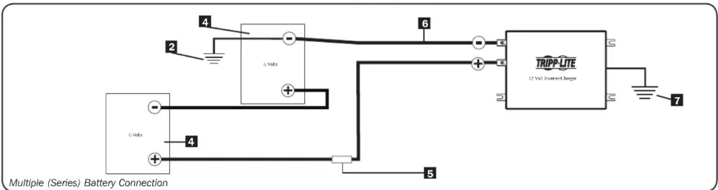
text_image
Multiple (Series) Battery Connection 6 Volts TRIPP-LITE 12 Volts Inverter/Charger 4 2 6 Volts 5 71 12 Volt Alternator (for Vehicular applications) 2 Vehicle or Earth Battery Ground 3 12 Volt Main Battery
4 6 Volt Series Batteries 5 UL-Listed Fuse & Fuse Block (mounted within 18 inches or 450 mm of the battery)
6 Large Diameter Cabling, Maximum 2/0 Gauge (9.3 mm) to Fit Terminals 7 Minimum 8 AWG (3.15 mm) Ground Wire
AC Input/Output Connection
To avoid overloading your Inverter/Charger, match the power requirements of the equipment you plan to run at any one time (add their total watts) with the output wattage capacity of your Inverter/Charger model (see Specifications). Do not confuse “continuous” wattage with “peak” wattage ratings. Most electric motors require extra power at start-up (“peak wattage”) than required to run continuously after start-up, sometimes over 100% more. Some motors, such as in refrigerators and pumps, start and stop intermittently according to demand, requiring “peak wattage” at multiple, unpredictable times during operation. Compact Fluorescent Lamps (CFLs) have high startup power requirements—typically 500% of their nameplate power rating. Larger CFL loads may be powered if they are started one bulb at a time. DoubleBoost™ Feature: Tripp Lite Inverter/Chargers deliver up to twice their nameplate rated wattage for up to 10 seconds,* providing the extra power needed to cold start heavy-duty tools and equipment. OverPower™ Feature: Tripp Lite Inverter/Chargers deliver up to 150% of their name-plate rated wattage for up to 1 hour,* providing plenty of reserve power to reliably support tools and equipment longer.
* Actual duration depends on model, battery age, battery charge level and ambient temperature.
AC Input Connection
Plug the Inverter/Charger's AC input cord into an outlet providing AC voltage that matches the voltage rating of your unit (see nameplate). Make sure that the circuit you connect your Inverter/Charger to has adequate overload protection, such as a circuit breaker or a fuse. Plug your equipment into the Inverter/Charger's AC output receptacles. Any equipment you connect to it will benefit from your Inverter/Charger's built-in ISOBAR® surge protection!
Service/Maintenance
Service
Before returning your Inverter/Charger for service, follow these steps:
- Review the installation and operation instructions to ensure that the service problem does not originate from a misreading of the instructions. Also, check that the circuit breaker(s) are not tripped.*
- If the problem continues, do not contact or return the Inverter/Charger to the dealer. Instead, call Tripp Lite at (773) 869-1234. A service technician will ask for the Inverter/Charger's model number, serial number and purchase date and will attempt to correct the problem over the phone.
- If the problem requires service, the technician will issue you a Returned Material Authorization (RMA) number, which is required for service. Securely pack the Inverter/Charger to avoid damage during shipping. Do not use Styrofoam beads for packaging.** Any damages (direct, indirect, special, incidental or consequential) to the Inverter/Charger incurred during shipment to Tripp Lite or an authorized Tripp Lite service center is not covered under warranty. Inverter/Chargers shipped to Tripp Lite or an authorized Tripp Lite service center must have transportation charges prepaid. Mark the RMA number on the outside of the package. If the Inverter/Charger is within the warranty period, enclose a copy of your sales receipt. Return the Inverter/Charger for service using an insured carrier to the address given to you by the Tripp Lite service technician.
* This is a common cause of service inquiries which can be easily remedied by following the resetting instructions in this manual. ** If you require packaging, the technician can arrange to send you proper packaging.
Maintenance
Your Inverter/Charger requires no maintenance and contains no user-serviceable or replaceable parts, but should be kept dry at all times. Periodically check, clean and tighten all cable connections, as necessary, both at the unit and at the battery.
Troubleshooting
Try these remedies for common Inverter/Charger problems before calling for assistance. Call Tripp Lite Customer Service at (773) 869-1234 before returning your unit for service.
SYMPTOM PROBLEMS CORRECTIONS
| No AC Output(All Indicator Lights are OFF) | Unit is not properly connected to utility power Connect unit to utility power. | |
| Operating Mode Switch is set to "DC OFF" and AC input is present. | Set Operating Mode Switch to "AUTO/REMOTE" or "CHARGE ONLY" | |
| This is normal when the Operating Mode Switch is set to "CHARGE ONLY" and AC input is absent. | No correction is required. AC output will return when AC input returns. Set Operating Mode Switch to "AUTO/REMOTE" if you require AC output. | |
| Output circuit breaker is tripped. Reset circuit breaker. | ||
| Unit has shut down due to battery overcharge (preventing battery damage). The problem may be with connected auxiliary chargers, if any, or with the unit's charger. | Disconnect any auxiliary chargers. Reset by moving Operating Mode Switch to "DC OFF". Wait 1 minute and switch to "AUTO/REMOTE" or "CHARGE ONLY." If unit remains in shutdown mode after several attempts to reset, contact Tripp Lite Customer Service for assistance. | |
| Unit has shut down due to excessive battery discharge. | Use an auxiliary charger* to raise battery voltage. Check external battery connections and fuse. Unit automatically resets when condition is cleared. | |
| Connected batteries are dead. Check and replace old batteries. | ||
| Unit has shut down due to overload. Reduce load. Reset by moving Operating Mode Switch to "DC OFF". Wait 1 minute. Switch to "AUTO/REMOTE" or "CHARGE ONLY". | ||
| Battery Not Recharging(AC Input Present) | Connected batteries are dead. Check and replace old batteries. | |
| Battery fuse* is blown. Check and replace fuse.* | ||
| Battery cabling* is loose. Check and tighten or replace cabling.* | ||
| Unit has shut down due to battery overcharge (preventing battery damage). The problem may be with connected auxiliary chargers, if any, or with the unit's charger. | Disconnect any auxiliary chargers. Reset by moving Operating Mode Switch to "DC OFF". Wait 1 minute and switch to "AUTO/REMOTE" or "CHARGE ONLY." If unit remains in shutdown mode after several attempts to reset, contact Tripp Lite Customer Service for assistance. | |
| Charger Enable/Inhibit Switch inadvertently set to "INHIBIT". | Set Charger Enable/Inhibit Switch to "ENABLE". | |
| Charger circuit breaker is tripped. Reset circuit breaker. | ||
| All Three "BATT VOLT/CHRG CURR" LEDs are slowly flashing (1⁄2 second flashes) with Operating Mode Switch in the "AUTO/REMOTE" position. | Battery is excessively discharged. Unit will shut down to prevent battery damage. | Use an auxiliary charger* to raise battery voltage. Check external battery connections and fuse. Unit automatically resets when condition is cleared. |
| All Three "BATT VOLT/CHRG CURR" LEDs are rapidly flashing (1⁄4 second flashes) with Operating Mode Switch in the "AUTO/REMOTE" position. | Battery is overcharged. Unit will shut down to prevent battery damage. The problem may be with connected auxiliary chargers, if any, or with the unit's charger. | Disconnect any auxiliary chargers. Reset by moving Operating Mode Switch to "DC OFF". Wait 1 minute and switch to "AUTO/REMOTE." If unit remains in shutdown mode after several attempts to reset, contact Tripp Lite Customer Service for assistance. |
| Red "LOW" Battery Indicator Light is flashing with Operating Mode Switch in the "AUTO/REMOTE" position. | Battery voltage is low. Unit has shut down to protect battery from damage. | If AC power (utility- or generator-supplied) is present, the unit will automatically reset itself and start recharging connected batteries. However, if an external charger is used to recharge the batteries, you will need to manually reset the unit by moving the Operating Mode Switch to "DC OFF" for two seconds then returning it to "AUTO/REMOTE". |
| False reading due to undersized or insufficiently connected DC cabling | Use sufficient size DC cable sufficiently connected to Inverter/Charger. | |
| Red "LOAD" Operation Indicator Light flashing | Inverter is overloaded. Unit will automatically shut down after 5 seconds. | Reduce load. Reset by moving Operating Mode Switch to "DC OFF". Wait 1 minute. Switch to "AUTO/REMOTE" or "CHARGE ONLY". |
* User-supplied.
Limited Warranty
Tripp Lite warrants its Inverter/Chargers to be free from defects in materials and workmanship for a 24 month period from the date of retail purchase by end user. Tripp Lite's obligation under this warranty is limited to repairing or replacing (at its sole option) any such defective products. To obtain service under this warranty you must obtain a Returned Material Authorization (RMA) number from Tripp Lite or an authorized Tripp Lite service center. Products must be returned to Tripp Lite or an authorized Tripp Lite service center with transportation charges prepaid and must be accompanied by a brief description of the problem encountered and proof of date and place of purchase. This warranty does not apply to equipment which has been damaged by accident, negligence or misapplication or has been altered or modified in any way, including opening of the unit's casing for any reason. This warranty applies only to the original purchaser who must have properly registered the product within 10 days of retail purchase.
EXCEPT AS PROVIDED HEREIN, TRIPP LITE MAKES NO WARRANTIES, EXPRESS OR IMPLIED, INCLUDING WARRANTIES OF MERCHANTABILITY AND FITNESS FOR A PARTICULAR PURPOSE. Some states do not permit limitation or exclusion of implied warranties; therefore, the aforesaid limitation(s) or exclusion(s) may not apply to the purchaser.
EXCEPT AS PROVIDED ABOVE, IN NO EVENT WILL TRIPP LITE BE LIABLE FOR DIRECT, INDIRECT, SPECIAL, INCIDENTAL OR CONSEQUENTIAL DAMAGES ARISING OUT OF THE USE OF THIS PRODUCT, EVEN IF ADVISED OF THE POSSIBILITY OF SUCH DAMAGE. Specifically, Tripp Lite is not liable for any costs, such as lost profits or revenue, loss of equipment, loss of use of equipment, loss of software, loss of data, costs of substitutes, claims by third parties, or otherwise.
WARRANTY REGISTRATION
Visit www.triplite.com/warranty today to register the warranty for your new Tripp Lite product. You'll be automatically entered into a drawing for a chance to win a FREE Tripp Lite product!*
* No purchase necessary. Void where prohibited. Some restrictions apply. See website for details.
Regulatory Compliance Identification Numbers: For the purpose of regulatory compliance certifications and identification, your Tripp Lite product has been assigned a unique series number. The series number can be found on the product nameplate label, along with all required approval makings and information. When requesting compliance for this product, always refer to the series number. The series number should not be confused with the makings name or model number of the product.
Tripp Lite follows a policy of continuous improvement. Product specifications are subject to change without notice.
Made in China.

text_image
TRIPP·LITE
1111 W. 35th Street, Chicago, IL 60609 USA • www.tripplite.com/support
1111 W. 35th Street, Chicago, IL 60609 USA • www.tripplite.com/support
Copyright © 2019 Tripp Lite. All rights reserved. PowerVerter® es una marca comercial de Tripp Lite
text_image
B4 B2E Group B Dip Switches A4 A2A GROUP A Dip Switches BATT VOLT CRR INPUT C/B 10Atext_image
A1 Level A A1 Level B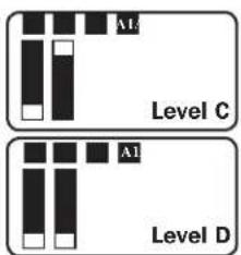
text_image
A1 Level C A1 Level Dtext_image
C 6.75 in. (17.1 cm) 7.87 in. (20 cm) B 4.5 in. (11.4 cm) 6.75 in. (17.1 cm)natural_image
Pure mechanical diagram showing a gear and shaft assembly without any text, numbers, or symbolsDC Connectors
1111 W. 35th Street, Chicago, IL 60609 USA • www.tripplite.com/support
Support technique/Maintenance 34
Dépannage 35
Garantie 36
English 1
Español 13
Русский 37

text_image
TRIPP·LITE
D'excellence Industrielle.
1111 W. 35th Street, Chicago, IL 60609 USA • www.tripplite.com/support
text_image
B41 B2B Group B Dip Switches A41 A2A CONTROL SWITCHES BATT ... THING VOLT CUB AIR METER INPUT C/B 10k Group A Dip Switchestext_image
C 6.75 in. (17.1 cm) 7.87 in. (20 cm) B 4.5 in. (11.4 cm) 6.75 in. (17.1 cm)natural_image
Pure mechanical diagram showing a lever and shaft assembly without any text, numbers, or symbolsConnecteurs CC
1111 W. 35th Street, Chicago, IL 60609 USA • www.tripplite.com/support
1111 W. 35th Street, Chicago, IL 60609 USA • www.tripplite.com/support
natural_image
Pure mechanical diagram showing a tool interacting with a component (no text or symbols)
1111 W. 35th Street, Chicago, IL 60609 USA • www.tripplite.com/support