
FSCC30PWB - Smart Home Furrion - Free user manual and instructions
Find the device manual for free FSCC30PWB Furrion in PDF.
| Product Type | MPPT Solar Charge Controller |
| Brand | Furrion |
| Model | FSCC30PWB-BL |
| Battery System Voltage | 12 V / 24 V |
| Max PV Power | 300 W |
| Max Charging Current | 25 A |
| Dimensions (L x H x D) | 225 x 220.6 x 68 mm |
| Net Weight | 1.85 kg |
| MPPT Tracking Efficiency | ≥ 99 % |
| Compatible Battery Types | Sealed Lead-Acid, AGM, LiFePO₄ |
| Charging Stages | Bulk, Absorption, Float |
| Reverse Polarity Protection | Yes (PV and battery) |
| Overheating Protection | Yes (automatic shutdown) |
| Battery Overcharge Protection | Yes |
| ECO Mode | Yes, standby current < 1 mA |
| Temperature Compensation | Yes (with optional sensor) |
| Communication Port | 4-pin RV-C port |
| LED Indicator | Yes (green/red, battery type) |
| Operating Temperature | -20°C to 40°C |
| Certifications | CSA, UL1741, FCC Class B |
| Box Contents | Controller, manual, warranty card, mounting bracket, screws |
Frequently Asked Questions - FSCC30PWB Furrion
User questions about FSCC30PWB Furrion
0 question about this device. Answer the ones you know or ask your own.
Ask a new question about this device
Download the instructions for your Smart Home in PDF format for free! Find your manual FSCC30PWB - Furrion and take your electronic device back in hand. On this page are published all the documents necessary for the use of your device. FSCC30PWB by Furrion.
USER MANUAL FSCC30PWB Furrion
FSCC30PW-BL, FSCC60PW-BL
FSCC30PWB-BL = FSCC30PW-BL ^+ FSCC60PWM-BL
FSCC60PWB-BL = FSCC60PW-BL ^+ FSCC60PWM-BL
Welcome
Thank you and congratulations for purchasing the Furrion® MPPT solar charge controller.
Before operating your new product, please read these instructions carefully. This instruction manual contains information for safe use, installation and maintenance of the product.
Please keep this instruction manual in a safe place for future reference. This will ensure safe use and reduce the risk of injury. Be sure to pass on this manual to new owners of this product.
The manufacturer does not accept responsibility for any damages due to not observing these instructions.
If you have any further questions regarding our products, please contact us at
support@furrion.com
Supplier's Declaration of Conformity
47 CFR § 2.1077 Compliance Information
Unique Identifier
Trade Name: Furrion
Model No.: FSCC30PW-BL, FSCC60PW-BL
Responsible Party - U.S. Contact Information
Furrion Innovation Center & Institute of Technology
52567 Independence Ct., Elkhart, IN 46514, USA
Toll free:1-888-354-5792; Email: support@furrion.com
FCC Compliance Statement
This device complies with Part 15 of the FCC Rules. Operation is subject to the following two conditions: (1) This device may not cause harmful interference, and (2) this device must accept any interference received, including interference that may cause undesired operation.
Contents
Welcome 1
Contents 2
Important Safety Instructions 3
General Safety Precautions 3
Charge Controller Safety 3
Battery Safety 3
About your Product 4
General Information 4
Key Features 4
Product Overview 5
Components 5
Charging Stages. 6
Installation 7
What's in the Box 7
Solar Charge Controller Mounting Bracket Installation (if included) 7
MPPT Solar Charge Controller Installation 7
PV Array Requirements 11
Wire and Cable Size 11
Operation 12
Protection 13
Care and Maintenance 14
Specifications 15
Troubleshooting 17
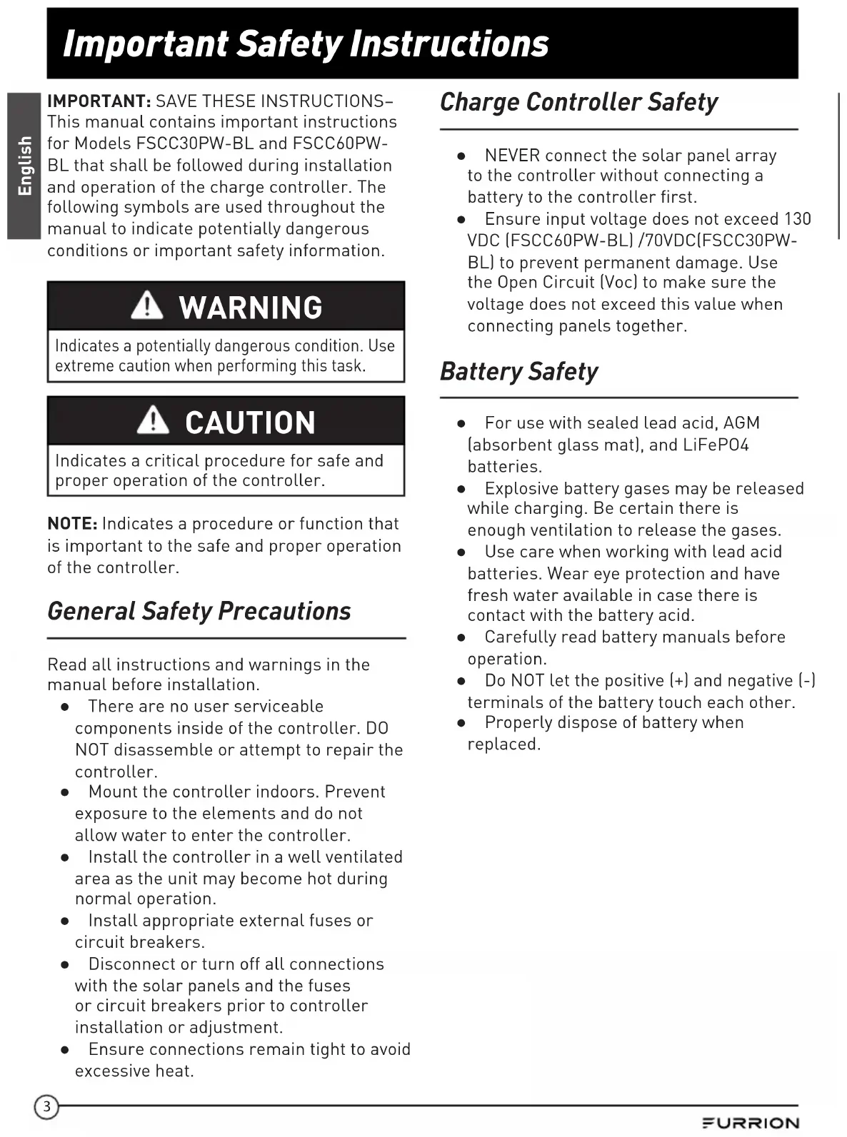
Important Safety Instructions
IMPORTANT: SAVE THESE INSTRUCTIONS- This manual contains important instructions for Models FSCC30PW-BL and FSCC60PWBL that shall be followed during installation and operation of the charge controller. The following symbols are used throughout the manual to indicate potentially dangerous conditions or important safety information.

WARNING
Indicates a potentially dangerous condition. Use extreme caution when performing this task.

CAUTION
Indicates a critical procedure for safe and proper operation of the controller.
NOTE: Indicates a procedure or function that is important to the safe and proper operation of the controller.
General Safety Precautions
Read all instructions and warnings in the manual before installation.
- There are no user serviceable components inside of the controller. DO NOT disassemble or attempt to repair the controller.
- Mount the controller indoors. Prevent exposure to the elements and do not allow water to enter the controller.
- Install the controller in a well ventilated area as the unit may become hot during normal operation.
- Install appropriate external fuses or circuit breakers.
- Disconnect or turn off all connections with the solar panels and the fuses or circuit breakers prior to controller installation or adjustment.
- Ensure connections remain tight to avoid excessive heat.
Charge Controller Safety
- NEVER connect the solar panel array to the controller without connecting a battery to the controller first.
- Ensure input voltage does not exceed 130 VDC (FSCC60PW-BL) /70VDC(FSCC30PW-BL) to prevent permanent damage. Use the Open Circuit (Voc) to make sure the voltage does not exceed this value when connecting panels together.
Battery Safety
- For use with sealed lead acid, AGM (absorbent glass mat), and LiFeP04 batteries.
- Explosive battery gases may be released while charging. Be certain there is enough ventilation to release the gases.
- Use care when working with lead acid batteries. Wear eye protection and have fresh water available in case there is contact with the battery acid.
- Carefully read battery manuals before operation.
- Do NOT let the positive (+) and negative (-) terminals of the battery touch each other.
- Properly dispose of battery when replaced.
About your Product
General Information
The Furrion Maximum Power Point Tracker (MPPT) series controllers can increase charge current by up to 30% compared to conventional Pulse Width Modulation (PWM) controllers. Furrion's sophisticated three stage charge control system can be configured to optimize charge parameters to precise battery requirements. The unit is fully protected against voltage spikes, over temperature, reverse battery and reverse PV connections. Automatic battery temperature sensors are also available to further protect and improve battery performance. The sensor element is environmentally sealed and encapsulated into a connection lug which directly connects to the battery terminals. Furrion MPPT charge controller includes RV-C communication bus interface in accordance with RV-C bus communication protocol.
Key Features
- Compatible with 12V or 24V battery system.
- Advanced maximum power point tracking technology to optimize the battery performance. High tracking efficiency of 99% .
- High open circuit voltage of PV input.
- Battery is active in low voltage state.
- Sealed, AGM and LiFePO4 Lithium battery option.
Economy (ECO) mode, automatic recognition of day and night. - Temperature compensation and corrective charging.
RV-C bus communication protocol. - Reverse protection: Polarity reverse for PV input and battery.
- Electronic protection: overcharging, over temperature, over PV input power.
- Easy to assemble: simply slide the controller into the Furrion Solar Charge Controller Mounting Bracket (model FSCC60PWM not included).
Product Overview
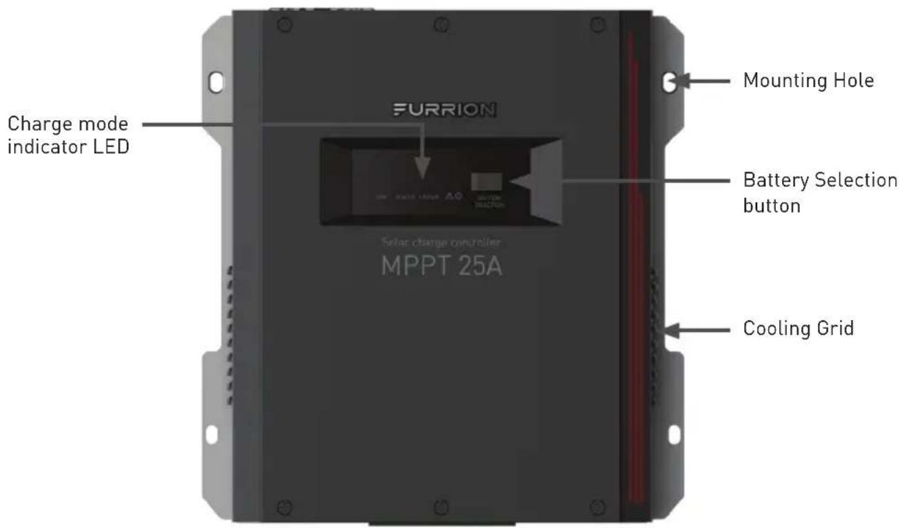
Components
The FSCC30PWB-BL and FSCC60PWB-BL are shipped with mounting bracket FSCC60PWM-BL. The FSCC30PW-BL and FSCC60PW-BL are shipped, without any additional components.
Components that require a separate purchase: Temperature sensor 5m (C-FSCC60PW-A01) or 10m (C-FSCC60PW-A02), the Solar Charge Controller Wall Mount Bracket (FSCC60PWM-BL).
| Furrion P/N Description | Accessory Type | |
| C-FSCC60PW-A01 5 meters | temperature sensor Optional accessory | |
| C-FSCC60PW-A02 10 meters | temperature sensor Optional accessory | |
| FSCC60PWM-BL | Solar charge controller wall mount bracket | Required component |
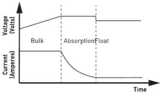
Charging Stages
Bulk stage
During this stage the MPPT controller delivers the maximum current to rapidly recharge the batteries. When the battery voltage reaches the absorption voltage, the MPPT controller activates the next stage (absorption).
Absorption stage
During this stage, the MPPT controller switches to the constant voltage mode, where the absorption voltage is applied to the battery. When the charge current decreases to the float current setting, the battery is fully charged and the MPPT controller switches to the float stage. The default time for the absorption stage is 120 minutes.
Float stage
During this stage, the float voltage is applied to the battery to maintain it in a fully charged state. When battery voltage drops below the recharge setting voltage a new bulk cycle will be triggered.
Installation
What's in the Box
Locate all of the following items that are included with the MPPT Charge Controller. If any item is damaged or missing, contact your dealer.
- MPPT Solar charge controller x 1
-Instruction Manual x 1
Warranty Card x 1
Solar Charge Controller Mounting Bracket x 1* -
Flat head screw (ST4.2*19mm) x 4 *
-
FSCC30PW-BL: 25A solar charge controller without mounting bracket
FSCC60PW-BL: 50A solar charge controller without mounting bracket
FSCC30PWB-BL: 25A solar charge controller with mounting bracket
FSCC60PWB-BL: 50A solar charge controller with mounting bracket
FSCC60PWM-BL: solar charge controller mounting bracket.

CAUTION
The controller requires at least 6" of clearance above and below for proper air flow. Ventilation is highly recommended if mounted in an enclosure.

WARNING:
Risk of explosion!
Do not install in a confined area where battery gas can accumulate.

WARNING:
Risk of electric shock! Exercise caution when handling solar wiring. The solar PV array may produce open-circuit voltages in excess of 100V when in sunlight. Make sure that all the power is turned off before installation and operation.
Solar Charge Controller Mounting Bracket Installation (if included)
Refer to separate Solar Charge Controller Mounting Bracket installation manual included in the packaging to install it.
MPPT Solar Charge Controller Installation
- Insert the MPPT controller into the Solar Charge Controller Mounting Bracket (FSCC60PWM-BL). (Figure 1)
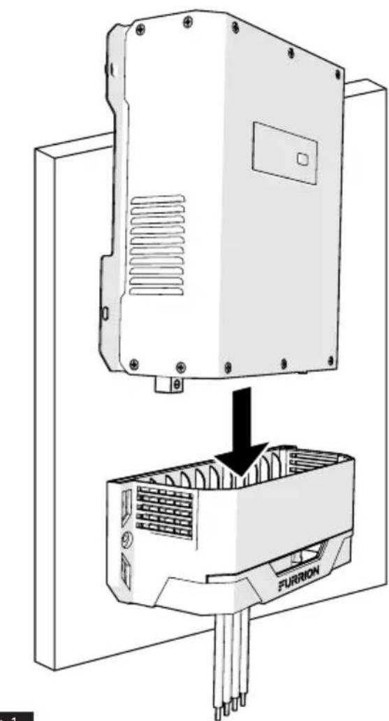
Fig.1
Installation
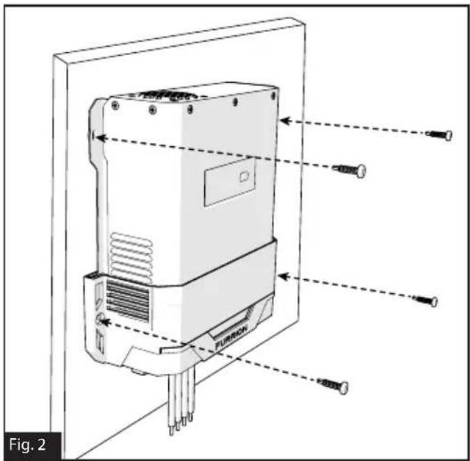
- Affix MPPT controller to the wall with 4 mounting screws (can be the standard RV screw) (not included). (Figure 2)
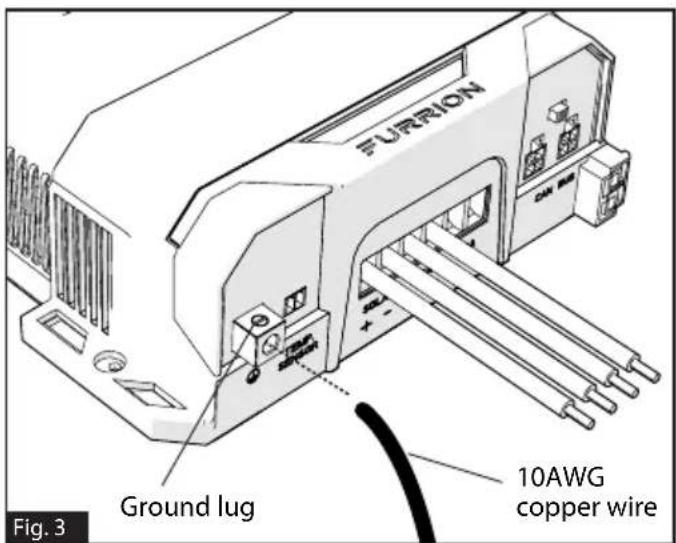
- Loosen the ground lug screw located on the left side of the mounting bracket. Insert a 10AWG copper wire from this lug to chassis ground. Tighten the ground lug screw securely. The suggested torque force should be 25lbs-inch. (Figure 3)
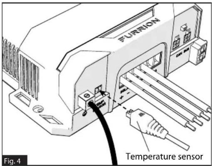
- Plug the temperature sensor connector (P/N: C-FSCC60PW-A01, C-FSCC60PW-A02) to the temperature sensor port (if applicable). (Figure 4)
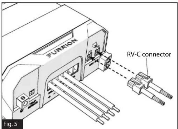
- Plug the RV-C connector to the MPPT controller (if applicable). (Figure 5)
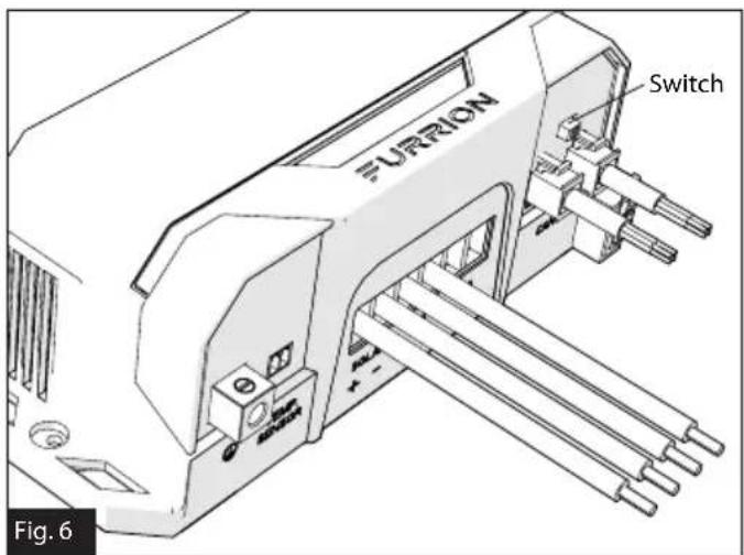
- Turn on the terminal resistance switch if the MPPT is the last device on the RV-C bus, otherwise leave it in the off position. (Figure 6)
Installation
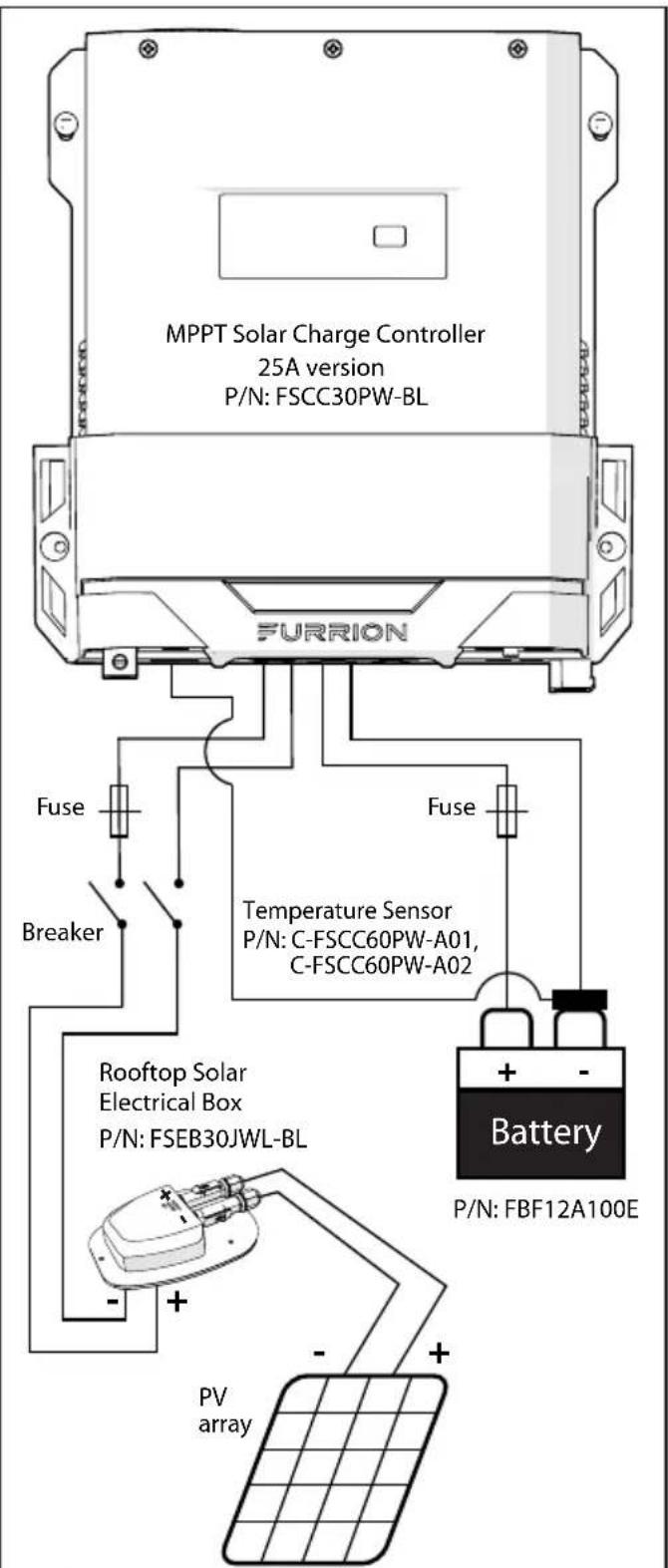
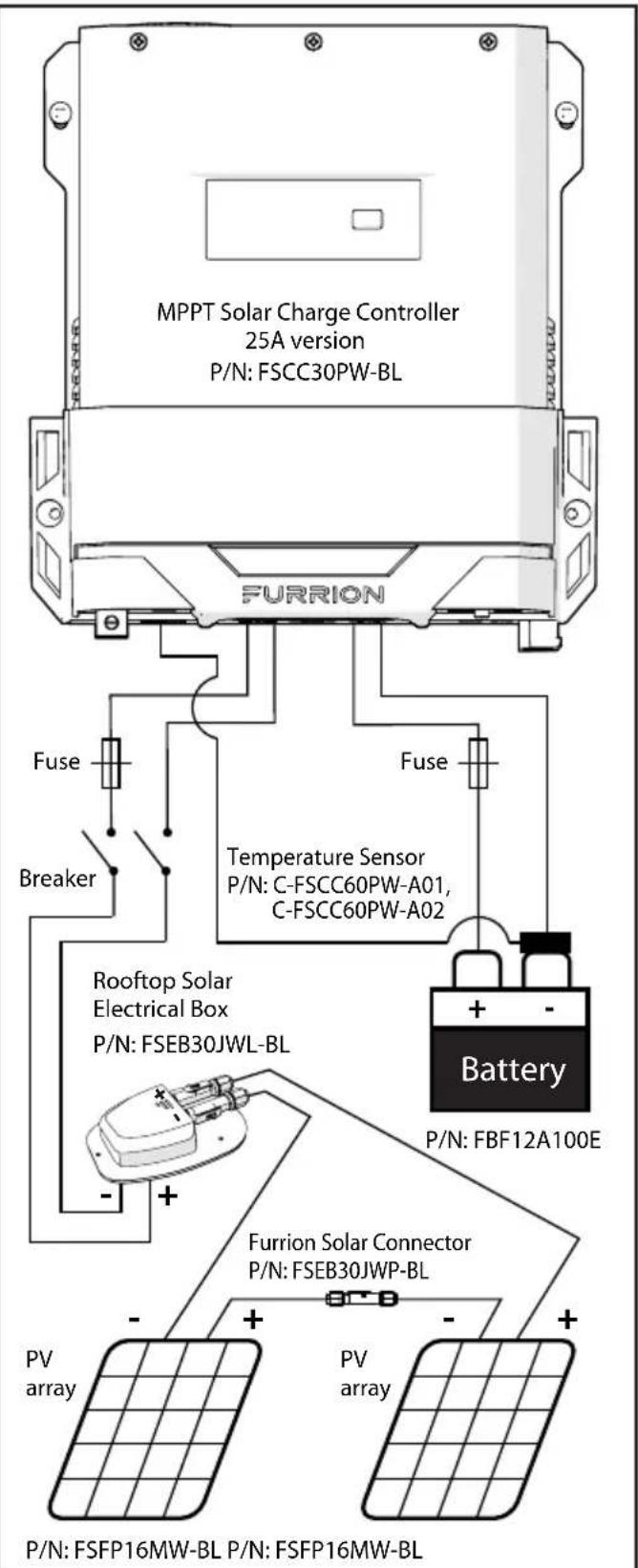
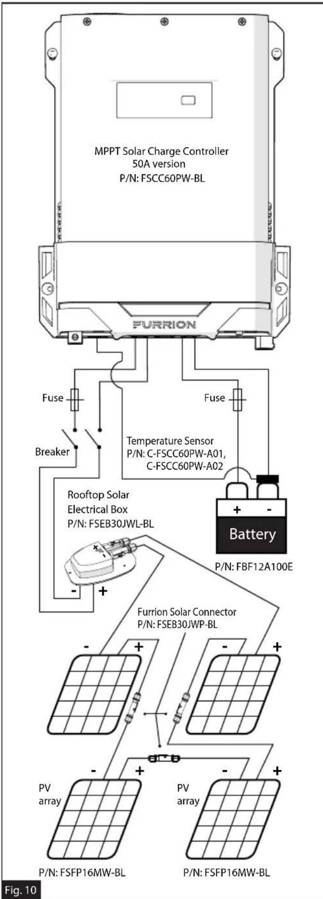
- Turn on the disconnect breaker for PV array (if applicable). (Figure 7/8/9/10)
P/N: FSFP16MW-BL
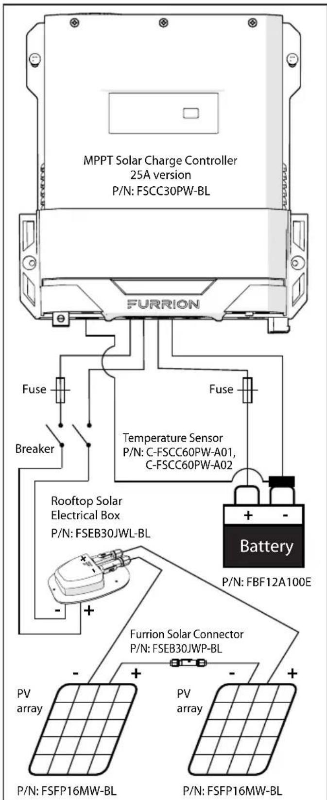
Fig.8
Fig. 7
Installation
Fig. 9
NOTE: If the battery cable is connected to the 50A port by RV manufacturer, a 25A MPPT controller will work without moving the wiring to the 25A port.
Installation
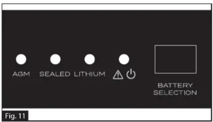
- Press the BATTERY SELECTION button to select the correct battery type. (Figure 11)
- Verify that system is operational, e.g. the charge LED is blinking or sold green light. (Figure 11)
PV Array Requirements
The acceptable PV array size as below:
| Model FSCC30 | PW-BL FSCC60P | W-BL |
| Maximum PV Power | 300W 600W | |
| Maximum PV open circuit voltage (Voc) | 70V 135V |
Wire and Cable Size
The wiring and installation methods must conform to all national and local electrical code requirements, and need to follow RVIA regulations.
PV Wire Size
Since the PV outputs can vary due to the array connection method, the minimum wire size must be in accordance with the maximum array short-circuit current. The PV array is suggested to be connected in series. Please use PV Photovoltaic wire, the reference size as below:
| PV short circuit current | Wire Gauge | Maximum Wire Length |
| 10A 12AWG 30FT |
NOTE: The PV wire size listed is only for reference. If there is a long distance between the PV array and the controller, larger wires can be used to reduce the voltage drop and improve performance.
Battery Cable Size
The battery cable size must conform to the rated current, the reference size as below:
| Model FSCC30 | PW-BL FSCC60P | W-BL |
| Maximum charge current | 25A 50A | |
| Cable Gauge 1 | DAWG 6AWG | |
| Maximum Cable Length | 15FT 15FT |
NOTE: The battery cable size is only for reference. If there is a long distance between the controller and the battery, larger cables can be used to reduce the voltage drop and improve performance.
Operation
| Operation | |
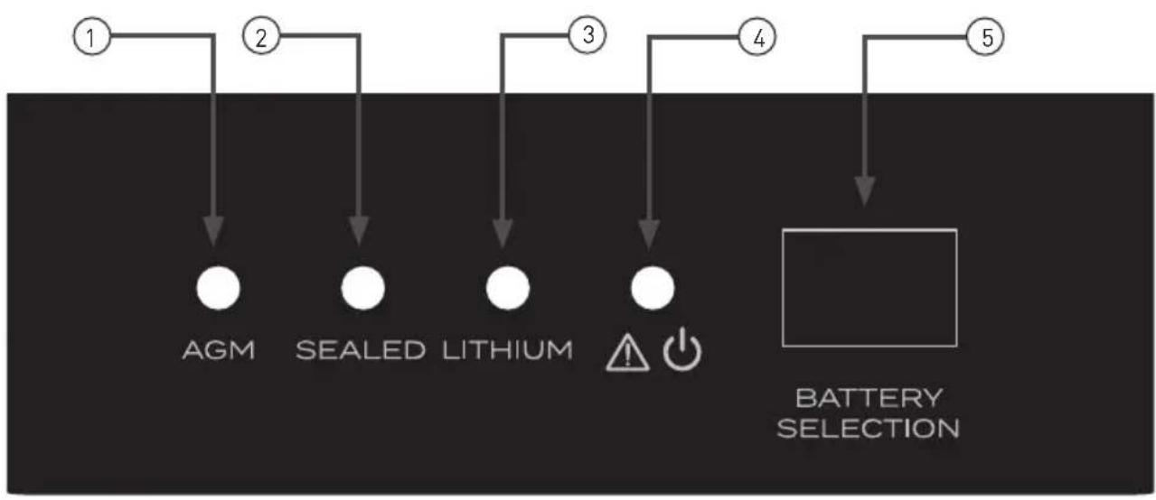
| ① | AGM battery mode indicator, this is a yellow LED, the LED will light when the MPPT solar controller is in AGM battery charge mode. |
| ② | SEALED battery mode indicator, this is a yellow LED, the LED will light when the MPPT solar controller is in sealed lead acid battery charge mode. |
| ③ | LITHIUM battery mode indicator, this is a green LED, the LED will light when the MPPT solar controller is in LiFePO4 lithium battery charge mode. |
| ④ | Charge and fault indicator, this is a bicolor LED, the LED will be red if there is a fault or if no battery is connected; the LED will be flashing green when the MPPT solar charge controller is charging the battery, the LED will be solid green when the battery is fully charged or in float charge stage. |
| ⑤ | Battery Selection button: press button once to activate ECO saving mode, press and hold button for 2 seconds to select different battery types. Factory default: press and hold button for 5 seconds. |
Protection
PV Over Current
The Solar Charge Controller will limit input power to 300W or 600W depending on model. A PV array with higher maximum power than the MPPT's rated power will be limited to the rated power of the device.
PV Short Circuit
When PV short circuit occurs, the controller will stop charging.
PV Reverse Polarity
The MPPT is protected against connecting PV leads in the reverse order.
Battery Reverse Polarity
The MPPT is protected against connecting battery leads in the reverse order.
Battery Over voltage
When battery voltage reaches the voltage set point of over charging voltage, the controller will stop charging the battery to protect the battery.
Controller Overheating
The MPPT controller will cut off its output when the internal temperature reaches a high level. The controller will resume operation when the internal temperature has decreased to an appropriate level.
Care and Maintenance
The following inspections and maintenance tasks are recommended at least twice per year for best performance:
- Make sure controller is firmly installed in a clean and dry location.
Make sure there is open air-flow around the controller. - Clean any dirt or dust that has accumulated on the cooling grid and fan grid.
- Check all exposed wires to make sure insulation has not been damage. Repair or replace wires if necessary.
- Tighten all terminal connections to suggested torque. Inspect for loose, broken, or burnt wire connections.
- Make sure that all ground connections are tight and secure.
- Confirm that all terminals are free of corrosion and damage to insulation.
- Confirm that lightning arrester is in good condition. Replace if necessary.

WARNING
Risk of electric shock!
Make sure that all the power is turned off before above inspection and maintenance tasks, and then follow the corresponding inspections and operations.
Specifications
English
| Specifications | ||
| MODEL NUMBER ITEM | FSCC30PW-BL FSCC60PW-BL | |
| Battery system voltage 12V/24V 12V | /24V | |
| Maximum PV power (Pmax) 300W 600W | ||
| Maximum solar panels in series | 150W*2 150W*4 | |
| MPPT tracking efficiency ≥99% ≥99% | ||
| ECO mode draw current <1mA <1mA | ||
| Minimum battery voltage for charging | 3V 3V | |
| Maximum MPPT charging current 25A 50A | ||
| Charging modes | Bulk voltage charging, Absorption charging, Float charging | Bulk voltage charging, Absorption charging, Float charging |
| Battery mode options | AGM, LiFePO4, Sealed lead acid | AGM, LiFePO4, Sealed lead acid |
| Bulk voltage | Sealed lead acid:14.4V/28.8V AGM:14.6V/29.2V Lithium:14.6V/29.2V | Sealed lead acid:14.4V/28.8V AGM:14.6V/29.2V Lithium:14.6V/29.2V |
| Float voltage | Sealed lead acid:13.2V/26.4V AGM:13.4V/26.8V Lithium:13.6V/27.2V | Sealed lead acid:13.2V/26.4V AGM:13.4V/26.8V Lithium:13.6V/27.2V |
| LED indicator YES YES | ||
| Automatic detection for 12V/24V battery | YES YES | |
| Automatic temperature compensation | YES YES | |
| Battery over charging protection YES | YES | |
| PV reverse protection | YES YES | |
| Battery reverse protection | YES YES | |
| Over temperature protection | YES YES | |
| Grounding | Common Negative | Common Negative |
| Communication port | 4Pin RV-C Socket | 4Pin RV-C Socket |
Specifications
| Specifications | ||
| MODEL NUMBER ITEM | FSCC30PW-BL FSCC60PW-BL | |
| Certificate | Listed to CSA, Compliance to UL1741 and CSA C22.2 No.107.1-16 | Listed to CSA, Compliance to UL1741 and CSA C22.2 No.107.1-16 |
| EMC | Meet FCC Part 15 Class B and CAN ICES-3(B)/NMB-3(B) | Meet FCC Part 15 Class B and CAN ICES-3(B)/NMB-3(B) |
| Operating Temperature Range -4°F~104°F / -20°C~40°C -4°F~104°F / -20°C~40°C | ||
| Storage Temperature Range | -22°F~+158°F / -30°C~+70°C, 10~95% RH | -22°F~+158°F / -30°C~+70°C, 10~95% RH |
| Dimensions | 225*220.6*68mm [87/8"*811/16"*211/16"] | 275*220.6*68mm [107/8"*811/16"*211/16"] |
| Net weight 1.85kg (2.2 lbs) 2.3kg (5.07 lbs) | ||
Note: When a battery temperature sensor is installed, the controller will increase or decrease battery charging voltage depending on the temperature of the battery, optimizing the charge to the battery and maintaining optimal battery performance.
Troubleshooting
| FAULT POSSIBLE | REASONS TROUBLESHOOTING | |
| No output voltage | No solar input or solar input voltage too low | Check if the switch for the solar input was turned on and that solar PV system is properly connected. |
| Fault LED be red | Battery polarity reverse | Check the connection of the battery, correct the connection if necessary. |
| PV reverse | Check the connection of the PV input, correct the connection if necessary. | |
| Battery over charge | Check if the battery is good, replace the battery if necessary. | |
| Battery disconnected | Check if the connection between battery to charger is loose, reconnect the battery if necessary. | |
| Battery not fully charged | Too much load connects to the battery | Remove the loads. |
| Battery temperature too low Use the battery temperature sensor. | ||
| Wrong battery type setting | Choose the correct battery type by pressing the Battery Selection button. | |
| Battery cable too small | Use larger gauge battery cable to reduce the voltage drops. | |
| Too little sun to power solar array | Reposition vehicle, if applicable. | |
| Battery not charged | Too much load connects to the battery | Remove the loads. |
| Battery damaged | Check the battery, replace the battery if necessary. | |
Bienvenue
Furrion Innovation Center & Institute of Technology
Furrion Innovation Center & Institute of Technology 52567
Independence Ct., Elkhart, IN 46514, USA
Linea gratuita:1-888-354-5792; Correo electrónico: support@furrion.com
Furrion Innovation Center & Institute of Technology
52567 Independence Ct., Elkhart, IN 46514, USA Toll free: 1-800-789-3341
Email: support@furrion.com
©2007-2020 Furrion Ltd. Furrion® and the Furrion logo are trademarks licensed for use by Furrion Ltd. and registered in the U.S. and other countries.
ZL201830164318.2 and other patents pending (FSCC30PW-BL, FSCC60PW-BL)
Patents pending (FSCC30PWB-BL, FSCC60PWB-BL, FSCC60PWM-BL)
- Welcome
- Supplier's Declaration of Conformity
- Contents
- Important Safety Instructions
- WARNING
- CAUTION
- General Safety Precautions
- Charge Controller Safety
- Battery Safety
- About your Product
- General Information
- Key Features
- Product Overview
- Components
- Charging Stages
- Bulk stage
- Absorption stage
- Float stage
- Installation
- What's in the Box
- WARNING:
- Solar Charge Controller Mounting Bracket Installation (if included)
- MPPT Solar Charge Controller Installation
- PV Array Requirements
- Wire and Cable Size
- PV Wire Size
- Battery Cable Size
- Operation
- Protection
- PV Over Current
- PV Short Circuit
- PV Reverse Polarity
- Battery Reverse Polarity
- Battery Over voltage
- Controller Overheating
- Care and Maintenance
- Specifications
- Troubleshooting
- Bienvenue
- Furrion Innovation Center & Institute of Technology
Brand : Furrion
Model : FSCC30PWB
Category : Smart Home