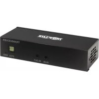
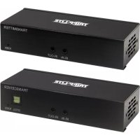
B160202HDSI - HDMI Extender Tripp Lite - Free user manual and instructions
Find the device manual for free B160202HDSI Tripp Lite in PDF.

| Product Type | HDMI over IP Extender Kit (transmitter + receiver) |
| Brand | Tripp Lite |
| Model | B160202HDSI |
| Category | HDMI Extender |
| Maximum Resolution | 1920 x 1080 (1080p) |
| Maximum Point-to-Point Distance | 100 m (328 ft) via Cat5e/6 cable |
| Maximum Distance via Network Switch | 200 m (656 ft): 100 m transmitter – switch + 100 m switch – receiver |
| Video Compression | H.264 |
| HDCP Compatible | Yes |
| 3D Compatible | Yes |
| IR Control Frequency | 20 to 60 kHz |
| RS-232 Serial Baud Rate | Up to 57,600 baud |
| Number of Channels | 64 (0-63) |
| Power Supply | External power adapter (included) |
| Approximate Dimensions (per unit) | 10 x 7 x 2 cm |
| Approximate Weight (per unit) | 0.3 kg |
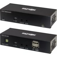
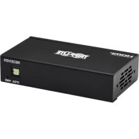
| Package Contents | Transmitter, receiver, power adapters (2), IR cables (2), serial adapters, mounting hardware, manual |
| Mounting | Wall, 19" rack, or pole (hardware included) |
| Maintenance and Cleaning | Disconnect before cleaning; use a dry, soft cloth; do not use liquid or abrasive products |
| Safety | Respect specified voltages; do not expose to moisture; use only the provided power supply |
| Spare Parts and Repairability | No user-serviceable parts; contact Tripp Lite for warranty service |
| Warranty | 1 year |
| General Information | Extension of HDMI, RS-232, and IR signals over IP network; requires Cat5e/6 cable; compatible with IGMP managed switches |
Frequently Asked Questions - B160202HDSI Tripp Lite
User questions about B160202HDSI Tripp Lite
0 question about this device. Answer the ones you know or ask your own.
Ask a new question about this device
Download the instructions for your HDMI Extender in PDF format for free! Find your manual B160202HDSI - Tripp Lite and take your electronic device back in hand. On this page are published all the documents necessary for the use of your device. B160202HDSI by Tripp Lite.
USER MANUAL B160202HDSI Tripp Lite
Audio/Video with RS-232 and IR Control over IP Extenders
Extender Kit Models:
B160-101-DPSI
B160-101-DPHDSI
B160-101-HDSI
B160-103-HDSI
B160-201-HSI
B160-202-HDSI
B160-301-HDSI
Transmitter Models:
B160-001-CSI
B160-001-DPSI
B160-001-HDSI
B160-001-VSI
Receiver Models:
B160-100-CSI
B160-100-DPSI
B160-100-HDSI
B160-100-VSI
B160-200-HSI
Español 25 • Français 50 • Русский 75
WARRANTY REGISTRATION
Register your product today and be automatically entered to win an ISOBAR surge protector in our monthly drawing!
www.tripplite.com/warranty


Manufacturing Excellence.
1111 W. 35th Street, Chicago, IL 60609 USA • www.tripplite.com/support
Copyright © 2019 Tripp Lite. All trademarks are the sole property of their respective owners.
Package Contents
| B160-001-CSI | B160-001-DPSI | B160-001-HDSI | B160-001-VSI | B160-100-CSI | B160-100-DPSI | B160-100-HDSI | B160-100-VSI | B160-200-HSI | B160-101-DPSI | B160-101-DPHDSI | B160-101-HDSI | B160-103-HDSI | B160-201-HSI | B160-202-HDSI | B160-301-HDSI | |
| Transmitter (T), Receiver (R), Kit (K) | TT | TT | RR | RR | RR | KK | KK | KK | K | |||||||
| External Power Supply 1 | 11 | 11 | 11 | 11 | 12 | 22 | 42 | 44 | ||||||||
| IR-In Cable 0 0 0 0 1 1 | 11 | 11 | 11 | 11 | 23 | |||||||||||
| IR-Out Cable 1 1 1 1 0 0 | 00 | 00 | 11 | 13 | 12 | 1 | ||||||||||
| 3.5 mm to DB9 M/F Adapter Cable | 110 | 10 | 00 | 00 | 11 | 030 | 21 | |||||||||
| 3.5 mm to DB9 M/M Adapter Cable | 000 | 01 | 10 | 11 | 11 | 011 | 23 | |||||||||
| HDMI to DVI Adapter Cable | 001 | 00 | 01 | 00 | 012 | 40 | 44 | |||||||||
| Mounting Hardware Y Y Y | Y Y Y Y | Y Y Y Y | Y Y Y Y | Y Y Y Y | Y Y Y | |||||||||||
| Owner's Manual Y Y Y Y | Y Y Y Y Y | Y Y Y Y Y | Y Y Y Y Y | Y Y Y Y |
Optional Accessories
- A008-006 Component Video Gold Cable – 6 ft.
• N202-Series Cat6, 24 AWG, Solid-Wire Patch Cables
• NSS-G16D2 16-Port Gigabit L2 Managed Switch with 8-Outlet PDU
• NSS-G24D2 24-Port Gigabit L2 Managed Switch with 12-Outlet PDU
• P502-Series VGA Cables with RGB Coax - P520-006 RS-232 Serial Extension Cable – 6 ft.
• P561-Series DVI-D Single-Link Cables
• P566-Series HDMI to DVI Adapter Cables
• P568-Series High-Speed HDMI Cables - P569-XXX-LOCK* High-Speed HDMI Cables with Ethernet and Locking Connectors
• P580-Series DisplayPort™ Cables
• P583-Series Mini DisplayPort to DisplayPort Cables
*XXX refers to the length, with cables available in 6 ft. (006), 10 ft. (010) and 15 ft. (015) lengths.
Product Features
- Extends and distributes audio/video, serial and IR control signals over Cat5/Cat6 cabling.
- Models available with Component Video + Stereo Audio, DisplayPort, HDMI**, and VGA + Stereo Audio.
- Converts source video to an IP-based signal that can be transmitted to and distributed through a network switch.
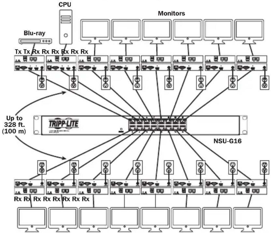
- Transmitters can be located up to 328 ft. (100 m) from the switch, with an additional 328 ft. (100 m) between the switch and the receiver, for a total distance of 656 ft. (200 m).
- Can also be used in a point-to-point installation where the transmitter directly connects to a receiver up to 328 ft. (100 m) away.
- Designed for managed network switches with IGMP, which allow login and remote management via the switch interface.
- Video source can be sent to any analog or digital display (e.g. Component Video to HDMI, VGA to HDMI, HDMI to DisplayPort, HDMI to HDMI).
- Display a single source on a single monitor or distribute a single signal to multiple monitors.
- B160-200-HSI and B160-201-HSI receiver units include two HDMI output ports for connection of two monitors.
- Connect up to 64 transmitters and 255 receivers in a single managed switch installation.
• Utilizes H.264 video compression standard. - Extends IR control signals that control a source (such as a Blu-ray™ player) from a remote display.
• Uses a 20 kHz to 60 kHz IR frequency.
• Supports RS-232 Serial baud rates up to 57600 bps. - VGA video models support video resolutions up to 1920 x 1440, including 1080p.
- DisplayPort and HDMI models support video resolutions up to 1920 x 1080 (1080p).
Product Features
- Component video models support video resolutions up to 1080i.
- Each transmitter features an HDMI output port for connecting a local monitor.
• HDCP and 3D compatible. - Includes mounting hardware for wall-mount, rack mount or pole mount installations.
- Plug and play; no software or drivers required.
**Connect a DVI source and/or monitor using an HDMI to DVI adapter (select models include an HDMI to DVI adapter). HDMI to DVI adapter cables (Tripp Lite P566-Series) are available, sold separately.
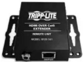
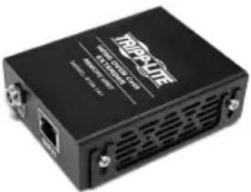
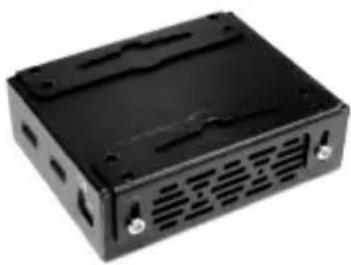
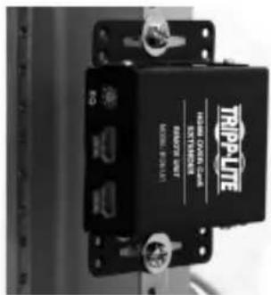
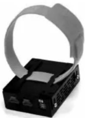
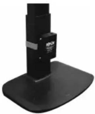
Mounting Instructions
Audio/Video over IP extenders include mounting hardware that allows for a variety of mounting options. The following images demonstrate these mounting methods.
Note: Model B126-1A1 is shown for illustrative purposes; installation for Audio/Video over IP extender units is the same.
Wall-mount
natural_image
Black rectangular electronic device casing with ventilation slots and mounting holes (no visible text or symbols)19" Rack-mount
Pole-mount
natural_image
Close-up of a black electronic device with a gray ribbon-like strap attached to its side (no visible text or symbols)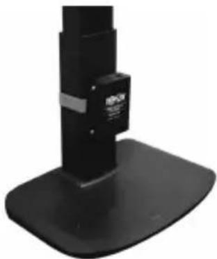
natural_image
Close-up of a black mechanical device with a base and top, no visible text or symbols.Point-to-Point Installation
Notes:
- Test to ensure the entire installation works properly before pulling cables through ceilings/walls.
- To achieve maximum distance and performance, use 24 AWG solid wire Cat5e/6 cable. Using stranded wire cable or cable with a gauge (AWG) size higher than recommended will result in a shorter extension distance. Higher gauge cabling (such as 26 AWG) has a limited transmission capability compared to lower-gauge cabling. All Tripp Lite N202-Series Cat6 cables use 24 AWG solid wire cabling. Extended lengths of 23 AWG solid wire Cat6a cable are available from Tripp Lite as a custom order.
-
Transmitter and receiver kits are available in DisplayPort, HDMI and VGA, but separate transmitters and receivers can be purchased in any combination (e.g. Component Video to HDMI, VGA to HDMI, HDMI to VGA, HDMI to DisplayPort).
-
Ensure all equipment to be connected is powered off.
- Connect the audio/video source to the transmitter unit's input port (see Optional Accessories for available Tripp Lite audio/video cables).
- (Optional) Connect the computer's DB9 port to the transmitter unit's serial port. Depending on the model, the serial port will be either DB9 or 3.5 mm. Models with 3.5 mm jacks include a 3.5 mm to DB9 adapter. Models with DB9 ports require standard RS-232 DB9 cable (sold separately) for connecting to a computer.
- (Optional) Connect the included IR-OUT cable to the transmitter unit's IR-OUT port. Place the sensor on the IR-OUT cable in an unobstructed area within clear view of the device being controlled.
Note: The IR-OUT cable receives the signal from the remote control and sends it to the device being controlled (e.g. Blu-ray player, etc.). - (Optional) Using an HDMI cable, connect a local monitor to the transmitter unit's HDMI output port (see Optional Accessories for available Tripp Lite HDMI cables).
- Connect the external power supply to the local transmitter unit and plug it into a Tripp Lite Surge Protector, Uninterruptible Power Supply (UPS) or Power Distribution Unit (PDU).
Point-to-Point Installation
- Press the Up / Down buttons to set the Channel Number (0-63) on the front of the transmitter unit to a number that will also be used on the receiver unit.
Note: A locking mechanism prevents the Channel Number from being unintentionally changed. When the Channel Number is locked, hold down the Up and Down buttons until the Channel Number starts blinking. Then navigate to the desired Channel using the Up / Down buttons. Once the desired Channel Number has been selected, lock the Channel Number by holding down the Up and Down buttons until the Channel Number stops blinking.
- Using Cat5e/6 cable, connect the transmitter unit's RJ45 Output port to the receiver unit's RJ45 Input port.
Note: The maximum allowable cable length from transmitter to receiver is 328 ft. (100 m).
-
Connect a monitor to the receiver unit's audio/video Output port (See Optional Accessories for available Tripp Lite audio/video cables).
-
(Optional) Connect the serial device's DB9 port to the receiver unit's serial port. Depending on the model, the serial port will be either DB9 or 3.5 mm. Models with 3.5 mm jacks include a 3.5 mm to DB9 adapter. Models with DB9 ports require standard RS-232 DB9 cable (sold separately) for connecting a device.
-
(Optional) Connect the included IR-IN cable to the receiver unit's IR-IN port. Place the sensor on the IR-IN cable in an unobstructed area within clear view of the device being controlled.
Note: The IR-IN cable accepts a signal from a remote control and sends it to a device being controlled on the other end of the installation.
- Connect the external power supply to the receiver unit and plug it into a Tripp Lite Surge Protector, Uninterruptible Power Supply (UPS) or Power Distribution Unit (PDU).
Point-to-Point Installation
- Press the Up / Down buttons to set the Channel Number (0-63) on the front of the receiver unit to a number also used on the transmitter unit.
Note: A locking mechanism prevents the Channel Number from being unintentionally changed. When the Channel Number is locked, hold down the Up and Down buttons until the Channel Number starts blinking. Then navigate to the desired Channel using the Up / Down buttons. Once the desired Channel Number has been selected, lock the Channel Number by holding down the Up and Down buttons until the Channel Number stops blinking.
- Power on all connected devices.
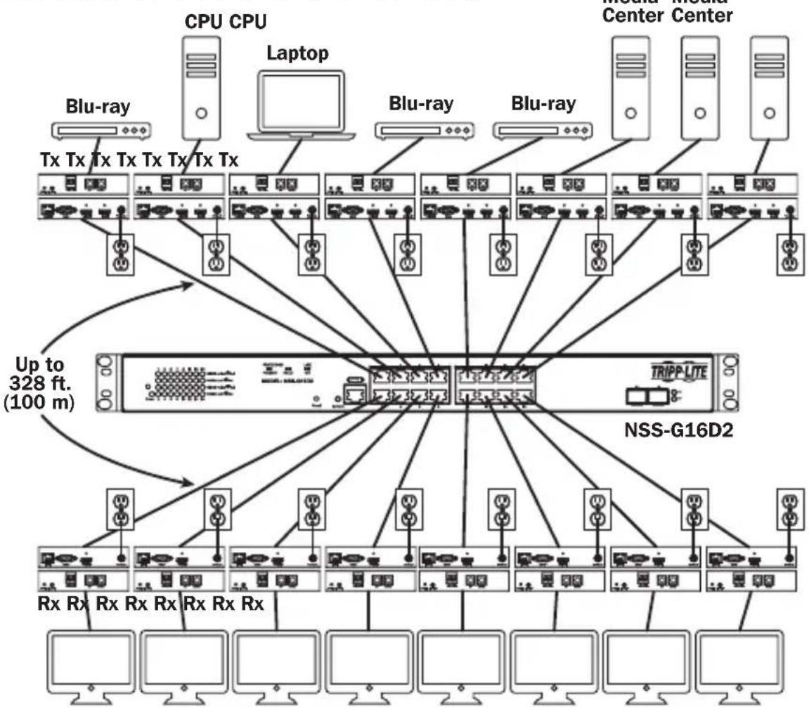
Point-to-Multipoint Installation – Managed Switch with IGMP
Notes:
- Test to ensure the entire installation works properly before pulling cables through ceilings/walls.
- To achieve maximum distance and performance, use 24 AWG solid wire Cat5e/6 cable. Using stranded wire cable or cable with a gauge (AWG) size higher than recommended will result in a shorter extension distance. Higher gauge cabling (such as 26 AWG) has a limited transmission capability compared to lower-gauge cabling. All Tripp Lite N202-Series Cat6 cables use 24 AWG solid wire cabling. Extended lengths of 23 AWG solid wire Cat6a cable are available from Tripp Lite as a custom order.
- B160-Series Audio/Video over IP Extenders are designed for use with a dedicated network switch. Connecting IP Extenders to a switch used with other networking equipment will result in degraded or non-functional product performance.
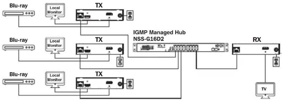
- The installation diagram on the next page shows HDMI transmitters and receivers only, though any combination of transmitters and receivers (e.g. Component Video, DisplayPort, HDMI, VGA) may be used. Up to 64 transmitters and 255 receivers can be connected in a single managed switch installation (the diagram shown stops at a single 16-port network switch).
- The installation diagram on the next page shows only required connections. Optional connections (such as the IR-IN and IR-OUT Cables) are not shown.
Point-to-Multipoint Installation – Managed Switch with IGMP
Installation Overview (All Models)
flowchart
graph TD
    subgraph Central Center
        A["CPU CPU"] --> B["Laptop"]
        C["Blu-ray"] --> D["Tx Tx Tx Tx Tx Tx Tx Tx"]
        E["Center Center"] --> F["BLu-ray"]
        G["Blu-ray"] --> H["Tx Tx Tx Tx Tx Tx Tx"]
        I["Center Center"] --> J["BLu-ray"]
        K["Blu-ray"] --> L["Tx Tx Tx Tx Tx Tx Tx"]
        M["Center Center"] --> N["BLu-ray"]
    end

    subgraph RSSGNDs
        O["TRIPP-LITE"] --> P["NSS-G16D2"]
    end

    A --> Q["Up to 328 ft. (100 m)"]
    C --> Q
    E --> Q
    G --> Q
    I --> Q
    M --> Q
    N --> Q
    O --> Q
    P --> Q
    R["Rx Rx Rx Rx Rx Rx Rx Rx Rx Rx Rx Rx Rx Rx Rx Rx Rx Rx Rx Rx Rx Rx Rx Rx Rx Rx Rx Rx Rx Rx Rx Rx Rx Rx Rx Rx Rx Rx Rx Rx Rx Rx Rx Rx Rx Rx Rx Rx Rx Rx Rx Rx Rx Rx Rx Rx Rx Rx Rx Rx Rx Rx Rx Rx Rx Rx Rx Rx Rx Rx Rx Rx Rx Rx Rx Rx Rx Rx Rx Rx Rx Rx Rx Rx Rx Rx Rx Rx Rx Rx Rx Rx Rx Rx Rx Rx Rx Rx Rx Rx Rx Dx"]
    style Central Center fill:#f9f,stroke:#333
    style RSSGNDs fill:#ccf,stroke:#333
Point-to-Multipoint Installation – Managed Switch with IGMP
B160-103-HDSI Kit
flowchart
graph TD
    A["Blu-ray"] --> B["Local Monitor"]
    B --> C["TX"]
    C --> D["TV"]
    E["Blu-ray"] --> F["Local Monitor"]
    F --> G["TX"]
    G --> H["IGMP Managed Hub NSS-G16D2"]
    H --> I["RX"]
    J["Blu-ray"] --> K["Local Monitor"]
    K --> L["TX"]
    L --> M["TV"]
    N["Local Monitor"] --> O["TX"]
    O --> P["TV"]
    Q["Local Monitor"] --> R["TX"]
    R --> S["TV"]
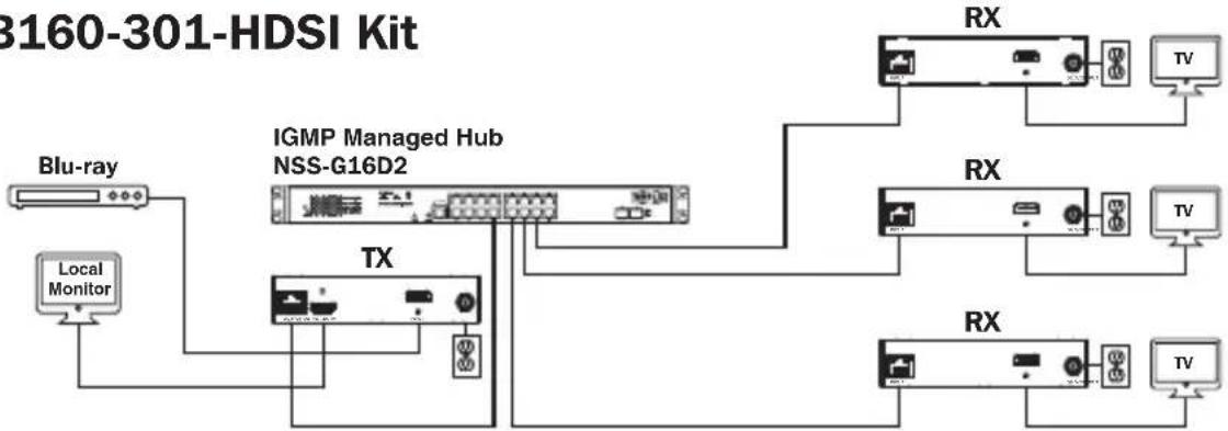
flowchart
graph TD
    A["Blu-ray"] --> B["Local Monitor"]
    B --> C["IGMP Managed Hub NSS-G16D2"]
    C --> D["TX"]
    D --> E["RX"]
    E --> F["TV"]
    C --> G["RX"]
    G --> H["TV"]
    C --> I["RX"]
    I --> J["TV"]
B160-202-HDSI Kit
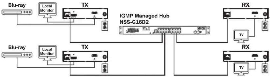
flowchart
graph TD
    A["Blu-ray"] --> B["Local Monitor"]
    C["Blu-ray"] --> D["Local Monitor"]
    E["TX"] --> F["IGMP Managed Hub NSS-G16D2"]
    G["TX"] --> F
    H["RX"] --> I["TV"]
    J["RX"] --> K["TV"]
    F --> L["Local Monitor"]
    F --> M["Local Monitor"]
    F --> N["Local Monitor"]
    F --> O["Local Monitor"]
    F --> P["Local Monitor"]
    F --> Q["Local Monitor"]
    F --> R["Local Monitor"]
    F --> S["Local Monitor"]
    F --> T["Local Monitor"]
    style F fill:#f9f,stroke:#333,stroke-width:2px
    style G fill:#ccf,stroke:#333,stroke-width:2px
    style J fill:#ccf,stroke:#333,stroke-width:2px
    style L fill:#dfd,stroke:#333,stroke-width:2px
    style M fill:#dfd,stroke:#333,stroke-width:2px
    style N fill:#dfd,stroke:#333,stroke-width:2px
    style O fill:#dfd,stroke:#333,stroke-width:2px
    style P fill:#dfd,stroke:#333,stroke-width:2px
    style Q fill:#dfd,stroke:#333,stroke-width:2px
    style R fill:#dfd,stroke:#333,stroke-width:2px
Point-to-Multipoint Installation – Managed Switch with IGMP
- Ensure all equipment to be connected is powered off.
- Connect the audio/video source to the transmitter unit's input port (see Optional Accessories for available Tripp Lite audio/video cables).
- (Optional) Connect the computer's DB9 port to the transmitter unit's serial port. Depending on the model, the serial port will be either DB9 or 3.5 mm. Models with 3.5 mm jacks include a 3.5 mm to DB9 adapter. Models with DB9 ports require standard RS-232 DB9 cable (sold separately) for connecting to a computer.
- (Optional) Connect the included IR-OUT cable to the transmitter unit's IR-OUT port. Place the sensor and cable in an unobstructed area within clear view of the device being controlled.
Note: The IR-OUT cable receives the signal from the remote control and sends it to the device being controlled (e.g. Blu-ray player, etc.).
-
(Optional) Using an HDMI cable, connect a local monitor to the transmitter unit's HDMI output port (see Optional Accessories for available Tripp Lite HDMI cables).
-
Set the Channel Number (0 to 63 are available) on the front of the transmitter to a desired number by pressing the Up / Down buttons. This number MUST be the same on all transmitter and receiver units in the installation. If you are using transmitter and receiver units that are all brand new, they will default to Channel Number 0 and you can leave the channel unchanged upon installation.
Note: A locking mechanism prevents the Channel Number from being unintentionally changed. When the Channel Number is locked, hold down the Up and Down buttons until the Channel Number starts blinking. Then navigate to the desired Channel using the Up / Down buttons. Once the desired Channel Number has been selected, lock the Channel Number by holding down the Up and Down buttons until the Channel Number stops blinking.
- Connect the RJ45 Output port on the transmitter unit to an RJ45 port on the network switch using Cat5e/6 cable.
Note: The maximum allowable cable length from transmitter to switch is 328 ft. (100 m).
Point-to-Multipoint Installation – Managed Switch with IGMP

Do not connect the external power supply to the transmitter at this time. The transmitter should not be powered on until all audio/video equipment is connected and powered on.
- To connect additional transmitter(s), repeat steps 2 through 7.
- Connect a monitor to the receiver unit's audio/video Output port (See Optional Accessories for available Tripp Lite audio/video cables).
- (Optional) Connect the serial device's DB9 port to the receiver unit's serial port. Depending on the model, the serial port will be either DB9 or 3.5 mm. Models with 3.5 mm jacks include a 3.5 mm to DB9 adapter. Models with DB9 ports require standard RS-232 DB9 cable (sold separately) for connecting a device.
- (Optional) Connect the included IR-IN cable to the receiver unit's IR-IN port. Place the sensor on the IR-IN cable in an unobstructed area within clear view of the remote control.
Note: The IR-IN cable accepts a signal from a remote control and sends it to a device being controlled on the other end of the installation.
- Set the Channel Number (0 to 63 are available) on the front of the receiver to a desired number by pressing the Up / Down buttons. This number MUST be the same on all transmitter and receiver units in the installation. If you are using transmitter and receiver units that are all brand new, they will default to channel number 0, and you can leave the channel unchanged upon installation.
Note: A locking mechanism prevents the Channel Number from being unintentionally changed. When the Channel Number is locked, hold down the Up and Down buttons until the Channel Number starts blinking. Then navigate to the desired Channel using the Up / Down buttons. Once the desired Channel Number has been selected, lock the Channel Number by holding down the Up and Down buttons until the Channel Number stops blinking.
- Connect the RJ45 Input port on the receiver unit to an RJ45 port on the network switch using Cat5e/6 cable.
Note: The maximum allowable cable length from receiver to switch is 328 ft. (100 m).
Point-to-Multipoint Installation – Managed Switch with IGMP

Do not connect the external power supply to the receiver at this time. The receiver should not be powered on until all audio/video equipment is connected and powered on.
- To connect additional receivers, repeat steps 9 through 13.
- Power on all connected devices.
- Connect the external power supplies to all transmitter and receiver units in the installation, then plug the external power supplies into Tripp Lite Surge Protectors, Uninterruptible Power Supplies (UPS) or Power Distribution Units (PDU).
Operation of Point-to-Multipoint Installation – Managed Switch with IGMP
Notes:
- B160-Series Audio/Video over IP Extenders are designed for use with a dedicated network switch. Connecting IP Extenders to a switch used with other networking equipment will result in degraded or non-functional product performance.
-
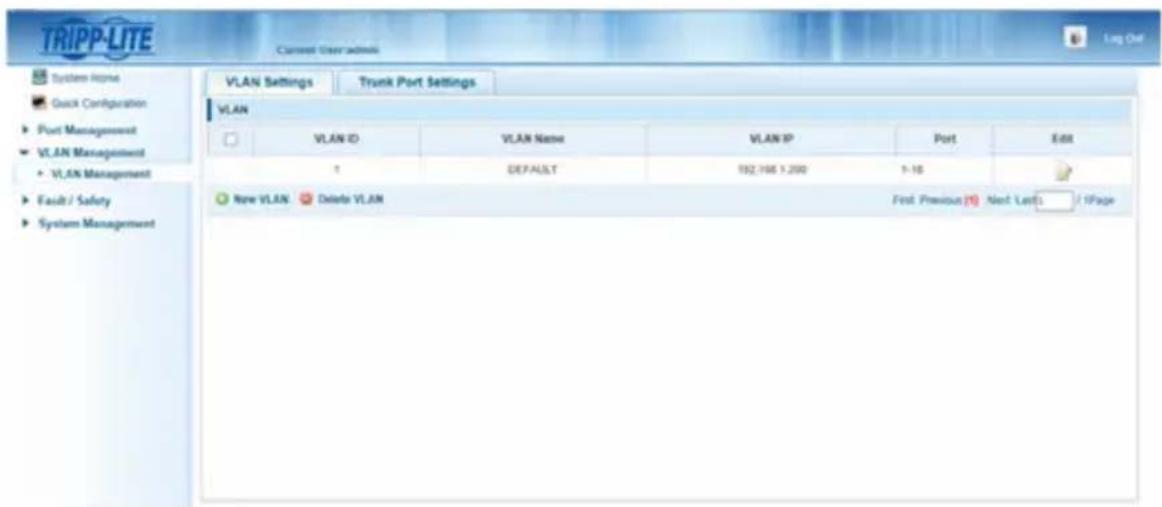
The model screenshots shown in the steps below are a Tripp Lite NSS-G16D2 Network Switch. Operation of different switches will vary by model.
-
Log into the network switch user interface.
- Navigate to the VLAN Management section.
Operation of Point-to-Multipoint Installation – Managed Switch with IGMP
- In the VLAN Management section, create a new VLAN for each transmitter in the installation. The transmitter port number should always be the first number in the VLAN, followed by the port numbers (separated by commas) of all receiver units that will be transmitting audio/video to and from the selected transmitter. The screenshot below shows VLAN's for four transmitters (VLAN0002 through VLAN0005). VLAN0002 represents the transmitter connected to port 1, the audio/video of which is transmitted to the receivers connected to ports 7 and 8. Similarly, VLAN0003 represents the transmitter connected to port 2, whose audio/video is transmitted to receivers connected to ports 9 and 10.
| VLAN ID | VLAN Name | VLAN IP | Port | Edit | |
| 1 | DEFAULT | 192 168.1.200 | 5-6.15-18 | ||
| 2 | VLAN0002 | 1,7-8 | |||
| 3 | VLAN0003 | 2,9-10 | |||
| 4 | VLAN0004 | 3,11-12 | |||
| 5 | VLAN0005 | 4,13-14 |
-
To switch the source of the audio/video on a receiver, go to and edit the VLAN of the associated transmitters to add/remove the desired ports.
-
As more transmitters and receivers get added to the installation, simply add additional VLANs for the new transmitters and add the new receivers to the VLANs of the desired transmitters.
Point-to-Multipoint Installation – Unmanaged Switch
Notes:
- Unmanaged switch installations are limited to two transmitter units. The number of receiver units is limited to the number of ports remaining on the unmanaged switch.
- Test to ensure the entire installation works properly before pulling cables through ceilings/walls.
- To achieve maximum distance and performance, use 24 AWG solid-wire Cat5e/6 cable. Using stranded-wire cable or cable with a gauge (AWG) size higher than recommended will result in a shorter extension distance. Higher-gauge cabling (such as 26 AWG) has a limited transmission capability compared to lower-gauge cabling. All Tripp Lite N202-Series Cat6 cables use 24 AWG solid-wire cabling. Extended lengths of 23 AWG solid-wire Cat6a cable are available from Tripp Lite as a custom order.
- B160-Series Audio/Video over IP Extenders are designed for use with a dedicated network switch. Connecting IP Extenders to a switch used with other networking equipment will result in degraded or non-functional product performance.
- The installation diagram on the next page shows HDMI transmitters and receivers only, though any combination of transmitters and receivers (e.g. Component Video, DisplayPort, HDMI, VGA) may be used.
- The installation diagram on the next page shows only required connections. Optional connections (such as the IR-IN and IR-OUT Cables) are not shown.
Point-to-Multipoint Installation – Unmanaged Switch
Installation Overview (All Models)
flowchart
graph TD
    CPU["CPU"] --> Tx["Tx Rx Rx Rx Rx Rx Rx"]
    CPU --> TxRx["Tx Rx Rx Rx Rx Rx Rx"]
    CPU --> TxRxRx["Tx Rx Rx Rx Rx Rx Rx"]
    CPU --> TxRxTx["Tx Rx Rx Rx Rx Rx Rx"]
    CPU --> TxRxTxTx["Tx Rx Rx Rx Rx Rx Rx"]
    CPU --> TxRxTxTx["Tx Rx Rx Rx Rx Rx Rx"]
    CPU --> TxRxTxTx["Tx Rx Rx Rx Rx Rx Rx"]
    CPU --> TxRxTxTx["Tx Rx Rx Rx Rx Rx Rx Rx"]
    CPU --> TxRxTxTx["Tx Rx Rx Rx Rx Rx Rx Rx"]
    CPU --> TxRxTxTx["Tx Rx Rx Rx Rx Rx Rx Rx"]
    CPU --> TxRxTxTx["Tx Rx Rx Rx Rx Rx Rx Rx"]
    CPU --> TxRxTxTx["Tx Rx Rx Rx Rx Rx Rx Rx"]
    CPU --> TxRxTxTx["Tx Rx Rx Rx Rx Rx Rx Rx"]
    CPU --> TxRxTxTxTx["Tx Rx Rx Rx Rx Rx Rx Rx"]
    CPU --> TxRxTxTxTx["Tx Rx Rx Rx Rx Rx Rx Rx"]
    CPU --> TxRxTxTxTx["Tx Rx Rx Rx Rx Rx Rx Rx"]
    CPU --> TxRxTxTxTx["Tx Rx Rx Rx Rx Rx Rx Rx"]
    CPU --> TxRxTxTxTx["Tx Rx Rx Rx Rx Rx Rx Rx"]
    CPU --> TxRxTxTxTx["Tx Rx Rx Rx Rx Rx RX"]
    CPU --> TxRxTxTxTx["Tx Rx Rx Rx Rx RX RX"]
    CPU --> TxRxTxTxTx["Tx Rx Rx Rx RX RX RX RX"]
    CPU --> TxRxTxTxTx["Tx Rx Rx RX RX RX RX RX"]
    CPU --> TxRxTxTxTx["Tx Rx RX RX RX RX RX RX"]
    CPU --> TxRxTxTxTx["Tx Rx RX RX RX RX RX RX"]
    CPU --> TxRxTxTxTx["Tx Rx RX RX RX RX RX RX"]
    CPU --> TxRxTxTxTx["Tx RuRXRxRxRxRxRxRxRxRxRxRxRxRxRxRxRxRxRxRxRxRxRxRxRxRxRxRxRxRxRxRxRxRxRxRxRxRxRxRxRxRxRxRxRxRxRxRxRxRxRxRxRxRxRxRxRxRxRxRxRxRxRxRxRxRxRxRxRxRxRxRxRxRxRxRxRxRxRxRxRxRxRxRxRxRxRxRxRxRxRxRxRxRxRxRxRxRxRxRxRxRxCx<br>    subgraph Transmitter<br>        TrIPP_LITE[TRIPP-LITE"]
        TrIPP_LITE --> TrIPP_LITE
        TrIPP_LITE --> TrIPP_LITE
        TrIPP_LITE --> TrIPP_LITE
        TrIPP_LITE --> TrIPP_LITE
        TrIPP_LITE --> TrIPP_LITE
        TrIPP_LITE --> TrIPP_LITE
        TrIPP_LITE --> TrIPP_LITE
        TrIPP_LITE --> TrIPP_LITE
        TrIPP_LITE --> TrIPP_LITE
        TrIPP_LITE --> TrIPP_LITE
    end
    TrIPP_LITE --> TrIPP_LITE
    TrIPP_LITE --> TrIPP_LITE
    TrIPP_LITE --> TrIPP_LITE
    TrIPP_LITE --> TrIPP_LITE
    TrIPP_LITE --> TrIPP_LITE
    TrIPP_LITE --> TrIPP_LITE
    TrIPP_LITE --> TrIPP_LITE
    TrIPP_LITE --> TrIPP_LITE
    TrIPP_LITE --> TrIPP_LITE
    TrIPP_LITE --> TrIPP_LITE
- Ensure all equipment to be connected is powered off.
-
Connect the audio/video source to the transmitter unit's input port (see Optional Accessories for available Tripp Lite audio/video cables).
-
(Optional) Connect the computer's DB9 port to the transmitter unit's serial port. Depending on the model, the serial port will be either DB9 or 3.5 mm. Models with 3.5 mm jacks include a 3.5 mm to DB9 adapter. Models with DB9 ports require standard RS-232 DB9 cable (sold separately) for connecting to a computer.
Point-to-Multipoint Installation – Unmanaged Switch
- (Optional) Connect the included IR-OUT cable to the transmitter unit's IR-OUT port. Place the sensor on the IR-OUT cable in an unobstructed area within clear view of the device being controlled.
Note: The IR-OUT cable receives the signal from the remote control and sends it to the device being controlled (e.g. Blu-ray player, etc.).
- (Optional) Using an HDMI cable, connect a local monitor to the transmitter unit's HDMI output port (see Optional Accessories for available Tripp Lite HDMI cables).
- Set the Channel Number (0 to 63 are available) on the front of the transmitter to a desired number by pressing the Up / Down buttons. The channel number of all transmitters in the installation MUST be different.
Note: A locking mechanism prevents the Channel Number from being unintentionally changed. When the Channel Number is locked, hold down the Up and Down buttons until the Channel Number starts blinking. Then navigate to the desired Channel using the Up / Down buttons. Once the desired Channel Number has been selected, lock the Channel Number by holding down the Up and Down buttons until the Channel Number stops blinking.
- Connect the RJ45 Output port on the transmitter unit to an RJ45 port on the network switch using Cat5e/6 cable.
Note: The maximum allowable cable length from receiver to switch is 328 ft. (100 m).

Do not connect the external power supply to the transmitter at this time. The transmitter should not be powered on until all audio/video equipment is connected and powered on.
- To connect an additional transmitter, repeat steps 2 through 7.
- Connect a monitor to the receiver unit's audio/video Output port (See Optional Accessories for available Tripp Lite audio/video cables).
- (Optional) Connect the serial device's DB9 port to the receiver unit's serial port. Depending on the model, the serial port will be either DB9 or 3.5 mm. Models with 3.5 mm jacks include a 3.5 mm to DB9 adapter. Models with DB9 ports require standard RS-232 DB9 cable (sold separately) for connecting a device.
Point-to-Multipoint Installation – Unmanaged Switch
- (Optional) Connect the included IR-IN cable to the receiver unit's IR-IN port. Place the sensor on the IR-IN cable in an unobstructed area within clear view of the remote control.
Note: The IR-IN cable accepts a signal from a remote control and sends it to a device being controlled on the other end of the installation.
- Set the Channel Number (0 to 63 are available) on the front of the receiver to match the channel number of the transmitter whose audio/video you want to receive by pressing the Up / Down buttons.
Note: A locking mechanism prevents the Channel Number from being unintentionally changed. When the Channel Number is locked, hold down the Up and Down buttons until the Channel Number starts blinking. Then navigate to the desired Channel using the Up / Down buttons. Once the desired Channel Number has been selected, lock the Channel Number by holding down the Up and Down buttons until the Channel Number stops blinking.
- Connect the RJ45 Input port on the receiver unit to an RJ45 port on the network switch using Cat5e/6 cable.
Note: The maximum allowable cable length from receiver to switch is 328 ft. (100 m).

Do not connect the external power supply to the receiver at this time. The receiver should not be powered on until all audio/video equipment is connected and powered on.
-
To connect additional receivers, repeat steps 9 through 13.
-
Power on all connected devices.
-
Connect the external power supplies to all transmitter and receiver units in the installation, then plug the external power supplies into Tripp Lite Surge Protectors, Uninterruptible Power Supplies (UPS) or Power Distribution Units (PDU).
-
Once in operation, change the monitor source signal by simply changing the channel of the corresponding receiver to match that of the transmitter with the desired source signal.
Troubleshooting
If unable to receive an acceptable image after following the installation instructions, try the following troubleshooting tips:
- Are the included external power supplies connected and plugged into a working power source? For the product to function properly, it must be connected to and receiving power from the external power supply.
- Was the power to the connected devices turned off prior to installation? If not, restart all connected devices.
- Were the connected audio/video devices powered on before the transmitter and receiver units? If not, disconnect power from all transmitter and receiver units, then power them back on.
- What resolution are you trying to obtain? Make sure the installation is within the maximum distance and resolution specs supported by the model as referenced in the Product Features section of this manual. If unable to obtain an acceptable image, try lowering the computer's video resolution or adjusting the refresh rate.
- What type of cabling is used in the installation? Inferior cabling can result in poor performance. It is important to use cables that support the desired video resolution. To achieve maximum distance and resolution, 24 AWG solid-wire Cat5e/6 cable or 23 AWG solid-wire Cat6a cable must be used. Tripp Lite's N202-Series Cat6 cables use 24 AWG solid wire, as do the N022-01K-GY (Cat5) and N222-01K-GY bulk cables. The audio/video cables used must also support the desired video resolution. Inexpensive, low quality cables may not support the maximum resolution. It is recommended that you use the Tripp Lite cables listed in the Optional Accessories section of this manual.
- Test the cables to ensure they are working properly. For example, connect the audio/video cable between a source and functioning monitor to ensure the cable is not defective. For Cat5e/6 cable, connect it between a computer and a network to verify it establishes a network connection.
Troubleshooting
- Check cabling for any damages that may have occurred during installation. If a cable connector is loosened from pulling through ceilings/wall or the cable jacket is damaged with the wiring exposed, maximum performance will not be achieved.
- Are the transmitter(s) and/or receiver(s) located in an area with exposure to higher temperatures? If the product is overheated, it will not function properly.
- Do not set identical channel numbers for transmitters in an Unmanaged Switch installation. Doing so will result in no signal being displayed on monitors connected to receivers assigned to the same channel number. If this happens, change the transmitters' channel numbers to unique numbers and assign the desired channel number to the affected receivers. If audio/video does not reappear after doing this, disconnect power from the affected transmitter and receiver units, wait 10 seconds, and reconnect the power.
- Do not connect more than two transmitters in an unmanaged switch installation. Unmanaged switch installations are limited to two transmitters, with the number of receivers being limited to the number of ports remaining on the unmanaged switch.
- Do not connect other networking equipment to the network switch. The B160-Series Audio/Video over IP Extenders are designed for use with a dedicated network switch. Connecting them to a switch used with other networking equipment will result in degraded or non-functional product performance.
Warranty and Product Registration
1-Year Warranty
Tripp Lite warrants its products to be free from defects in materials and workmanship for a period of one (1) year from the date of initial purchase. Tripp Lite's obligation under this warranty is limited to repairing or replacing (at its sole option) any such defective products. To obtain service under this warranty, you must obtain a Returned Material Authorization (RMA) number from Tripp Lite or an authorized Tripp Lite service center. Products must be returned to Tripp Lite or an authorized Tripp Lite service center with transportation charges prepaid and must be accompanied by a brief description of the problem encountered and proof of date and place of purchase. This warranty does not apply to equipment, which has been damaged by accident, negligence or misapplication or has been altered or modified in any way.
EXCEPT AS PROVIDED HEREIN, Tripp Lite MAKES NO WARRANTIES, EXPRESS OR IMPLIED, INCLUDING WARRANTIES OF MERCHANTABILITY AND FITNESS FOR A PARTICULAR PURPOSE. Some states do not permit limitation or exclusion of implied warranties; therefore, the aforesaid limitation(s) or exclusion(s) may not apply to the purchaser.
EXCEPT AS PROVIDED ABOVE, IN NO EVENT WILL Tripp Lite BE LIABLE FOR DIRECT, INDIRECT, SPECIAL, INCIDENTAL OR CONSEQUENTIAL DAMAGES ARISING OUT OF THE USE OF THIS PRODUCT, EVEN IF ADVISED OF THE POSSIBILITY OF SUCH DAMAGE. Specifically, Tripp Lite is not liable for any costs, such as lost profits or revenue, loss of equipment, loss of use of equipment, loss of software, loss of data, costs of substitutes, claims by third parties, or otherwise.
PRODUCT REGISTRATION
Visit www.triplite.com/warranty today to register your new Tripp Lite product. You'll be automatically entered into a drawing for a chance to win a FREE Tripp Lite product!*
* No purchase necessary. Void where prohibited. Some restrictions apply. See website for details.
FCC Notice, Class B
This device complies with part 15 of the FCC Rules. Operation is subject to the following two conditions: (1) This device may not cause harmful interference, and (2) this device must accept any interference received, including interference that may cause undesired operation.
Note: This equipment has been tested and found to comply with the limits for a Class B digital device, pursuant to part 15 of the FCC Rules. These limits are designed to provide reasonable protection against harmful interference in a residential installation. This equipment generates, uses and can radiate radio frequency energy and, if not installed and used in accordance with the instructions, may cause harmful interference to radio communications. However, there is no guarantee that interference will not occur in a particular installation. If this equipment does cause harmful interference to radio or television reception, which can be determined by turning the equipment off and on, the user is encouraged to try to correct the interference by one or more of the following measures:
- Reorient or relocate the receiving antenna.
- Increase the separation between the equipment and receiver.
- Connect the equipment into an outlet on a circuit different from that to which the receiver is connected.
- Consult the dealer or an experienced radio/TV technician for help.
Any changes or modifications to this equipment not expressly approved by Tripp Lite could void the user's authority to operate this equipment.
Tripp Lite has a policy of continuous improvement. Specifications are subject to change without notice. Photos and illustrations may differ slightly from actual products.


Manufacturing Excellence,
1111 W. 35th Street, Chicago, IL 60609 USA • www.tripplite.com/support
Copyright © 2019 Tripp Lite.
natural_image
Three black TRIPP-LITE wireless devices with visible ports and ventilation slots, no text or symbols on the devices themselves.natural_image
Three black electronic devices: a triplite sensor module, a cable strap device, and a mounted DC motor stand (no visible text or symbols)1111 W. 35th Street, Chicago, IL 60609 USA • www.tripplite.com/support
natural_image
Black rectangular electronic device casing with ventilation slots and mounting holes (no visible text or symbols)natural_image
Close-up of a black electronic device with a gray plastic strap and control panel (no visible text or symbols)Montage sur poteau
natural_image
Close-up of a black mechanical device with a base, no visible text or symbols1111 W. 35th Street, Chicago, IL 60609 USA • www.tripplite.com/support
1111 W. 35th Street, Chicago, IL 60609 USA • www.tripplite.com/support
natural_image
Black plastic electronic device casing with ventilation slots and mounting holes (no visible text or symbols)natural_image
Close-up of a black electronic device with a gray plastic strap and control panel (no visible text or symbols)
natural_image
Close-up of a black mechanical device with a base, no visible text or symbols1111 W. 35th Street, Chicago, IL 60609 USA • www.tripplite.com/support