AutoLink AL301 - Car diagnostic tool Autel - Free user manual and instructions
Find the device manual for free AutoLink AL301 Autel in PDF.

User questions about AutoLink AL301 Autel
0 question about this device. Answer the ones you know or ask your own.
Ask a new question about this device
Download the instructions for your Car diagnostic tool in PDF format for free! Find your manual AutoLink AL301 - Autel and take your electronic device back in hand. On this page are published all the documents necessary for the use of your device. AutoLink AL301 by Autel.
USER MANUAL AutoLink AL301 Autel
- SAFETY PRECAUTIONS AND WARNINGS.... 1
- GENERAL INFORMATION...... 2
2.1 ON-BOARD DIAGNOSTICS (OBD) II 2
2.2 DIAGNOSTIC TROUBLE CODES (DTCs) 2
2.3 LOCATION OF THE DATA LINK CONNECTOR (DLC) 3
2.4 OBD II READINESS MONITORS 4
2.5 OBD II MONITOR READINESS STATUS.... 5
2.6 OBD II DEFINITIONS 6
- USING THE SCAN TOOL......8
3.1 TOOL DESCRIPTION 8
3.2 SPECIFICATIONS....8
3.3 PRODUCT FEATURES....9
3.4 VEHICLE COVERAGE 9
- OPERATING INSTRUCTIONS....11
4.1 READING CODES ...... 11
4.2 ERASING CODES....13
4.3 RETRIEVING I/M READINESS STATUS.... 15
4.4 VIEWING VIN NUMBER 17
4.5 RESCANNING DATA 17
- WARRANTY AND SERVICE....19
5.1. LIMITED ONE YEAR WARRANTY 19
5.2. SERVICE PROCEDURES.... 19
- DIAGNOSTIC TROUBLE CODE (DTC) DEFINITIONS .... 20
1. Safety Precautions and Warnings
To prevent personal injury or damage to vehicles and/or the scan tool, read this instruction manual first and observe the following safety precautions at a minimum whenever working on a vehicle:
● Always perform automotive testing in a safe environment.
- Wear safety eye protection that meets ANSI standards.
- Keep clothing, hair, hands, tools, test equipment, etc. away from all moving or hot engine parts.
- Operate the vehicle in a well ventilated work area: Exhaust gases are poisonous.
- Put blocks in front of the drive wheels and never leave the vehicle unattended while running tests.
- Use extreme caution when working around the ignition coil, distributor cap, ignition wires and spark plugs. These components create hazardous voltages when the engine is running.
- Put the transmission in PARK (for automatic transmission) or NEUTRAL (for manual transmission) and make sure the parking brake is engaged.
- Keep a fire extinguisher suitable for gasoline/chemical/electrical fires nearby.
- Don’t connect or disconnect any test equipment while the ignition is on or the engine is running.
- Keep the scan tool dry, clean, free from oil/water or grease. Use a mild detergent on a clean cloth to clean the outside of the scan tool, when necessary.
2. General Information
2.1 On-Board Diagnostics (OBD) II
The first generation of On-Board Diagnostics (called OBD I) was developed by the California Air Resources Board (ARB) and implemented in 1988 to monitor some of the emission control components on vehicles. As technology evolved and the desire to improve the On-Board Diagnostic system increased, a new generation of On-Board Diagnostic system was developed. This second generation of On-Board Diagnostic regulations is called "OBD II".
The OBD II system is designed to monitor emission control systems and key engine components by performing either continuous or periodic tests of specific components and vehicle conditions. When a problem is detected, the OBD II system turns on a warning lamp (MIL) on the vehicle instrument panel to alert the driver typically by the phrase of “Check Engine” or “Service Engine Soon”. The system will also store important information about the detected malfunction so that a technician can accurately find and fix the problem. Here below follow three pieces of such valuable information:
1) Whether the Malfunction Indicator Light (MIL) is commanded 'on' or 'off';
2) Which, if any, Diagnostic Trouble Codes (DTCs) are stored;
3) Readiness Monitor status.
2.2 Diagnostic Trouble Codes (DTCs)
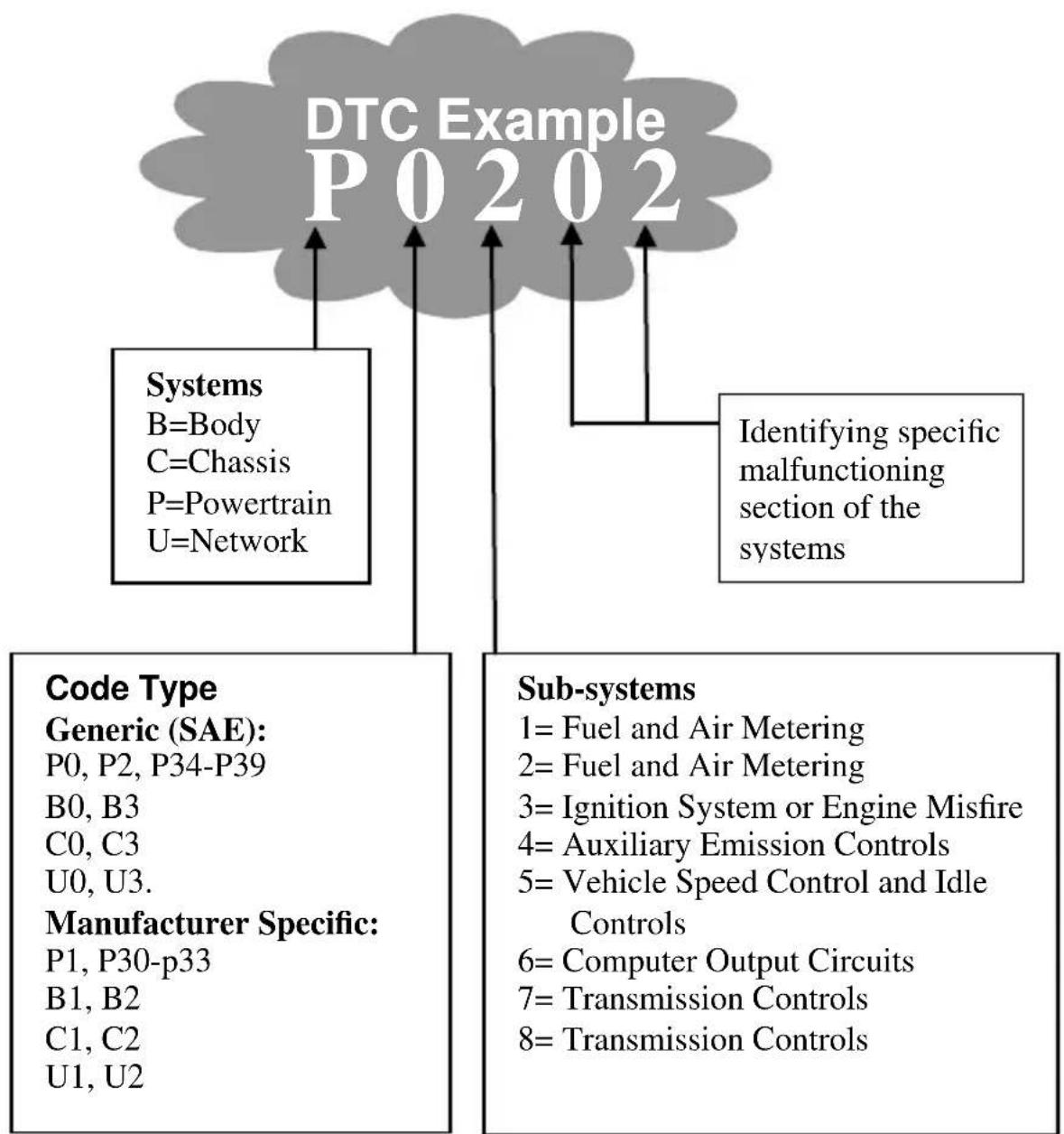
OBD II Diagnostic Trouble Codes are codes that are stored by the on-board computer diagnostic system in response to a problem found in the vehicle. These codes identify a particular problem area and are intended to provide you with a guide as to where a fault might be occurring within a vehicle. OBD II Diagnostic Trouble Codes consists of a five-digit alphanumeric code. The first character, a letter, identifies which control system sets the code. The other four characters, all numbers, provide additional information on where the DTC originated and the operating conditions that caused it to set. Here below is an example to illustrate the structure of the digits:
flowchart
graph TD
    A["DTC Example P0202"] --> B["Systems"]
    A --> C["Identifying specific malfunctioning section of the systems"]
    B --> D["Code Type Generic (SAE): P0, P2, P34-P39"]
    B --> E["Sub-systems"]
    D --> F["B0, B3"]
    D --> G["C0, C3"]
    D --> H["U0, U3."]
    D --> I["P1, P30-p33"]
    D --> J["B1, B2"]
    D --> K["C1, C2"]
    D --> L["U1, U2"]
    C --> M["Manufacturer Specific: 1= Fuel and Air Metering"]
    C --> N["Manufacturer Specific: 2= Fuel and Air Metering"]
    C --> O["Manufacturer Specific: 3= Ignition System or Engine Misfire"]
    C --> P["Manufacturer Specific: 4= Auxiliary Emission Controls"]
    C --> Q["Manufacturer Specific: 5= Vehicle Speed Control and Idle Controls"]
    C --> R["Manufacturer Specific: 6= Computer Output Circuits"]
    C --> S["Manufacturer Specific: 7= Transmission Controls"]
    C --> T["Manufacturer Specific: 8= Transmission Controls"]
2.3 Location of the Data Link Connector (DLC)
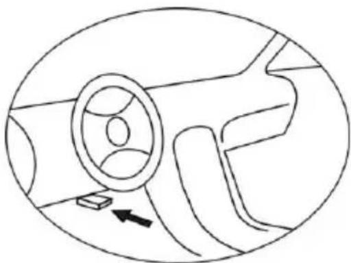
The DLC (Data Link Connector or Diagnostic Link Connector) is the standardized 16-cavity connector where diagnostic scan tools interface with the vehicle's on-board computer. The DLC is usually located 12 inches from the center of the instrument panel (dash), under or around the driver's side for most vehicles. If Data Link Connector is not located under dashboard, a label should be there telling location. For some Asian and European vehicles, the DLC is located behind the ashtray and the ashtray must be removed to access the connector. If the DLC cannot be found, refer to the vehicle's service manual for the location.
natural_image
Line drawing of a car interior showing steering wheel and dashboard (no text or symbols)2.4 OBD II Readiness Monitors
An important part of a vehicle's OBD II system is the Readiness Monitors, which are indicators used to find out if all of the emissions components have been evaluated by the OBD II system. They are running periodic tests on specific systems and components to ensure that they are performing within allowable limits.
Currently, there are eleven OBD II Readiness Monitors (or I/M Monitors) defined by the U.S. Environmental Protection Agency (EPA). Not all monitors are supported by all vehicles and the exact number of monitors in any vehicle depends on the motor vehicle manufacturer's emissions control strategy.
Continuous Monitors -- Some of the vehicle components or systems are continuously tested by the vehicle's OBD II system, while others are tested only under specific vehicle operating conditions. The continuously monitored components listed below are always ready:
1) Misfire
2) Fuel System
3) Comprehensive Components (CCM)
Once the vehicle is running, the OBD II system is continuously checking the above components, monitoring key engine sensors, watching for engine misfire, and monitoring fuel demands.
Non-Continuous Monitors -- Unlike the continuous monitors, many emissions and engine system components require the vehicle to be operated under specific conditions before the monitor is ready. These monitors are termed non-continuous monitors and are listed below:
1) EGR System
2) O2 Sensors
3) Catalyst
4) Evaporative System
5) O2 Sensor Heater
6) Secondary air
7) Heated Catalyst
8) A/C system
2.5 OBD II Monitor Readiness Status
OBD II systems must indicate whether or not the vehicle's PCM's monitor system has completed testing on each component.
Components that have been tested will be reported as “Ready”, or “Complete”, meaning they have been tested by the OBD II system.
The purpose of recording readiness status is to allow inspectors to determine if the vehicle's OBD II system has tested all the components and/or systems.
The power-train control module (PCM) sets a monitor to “Ready” or “Complete” after an appropriate drive cycle has been performed. The drive cycle that enables a monitor and sets readiness codes to “Ready” varies for each individual monitor. Once a monitor is set as “Ready” or “Complete”, it will remain in this state. A number of factors, including erasing of diagnostic trouble codes (DTCs) with a scan tool or a disconnected battery, can result in Readiness Monitors being set to “Not Ready”. Since the three continuous monitors are constantly evaluating, they will be reported as “Ready” all of the time. If testing of a particular supported non-continuous monitor has not been completed, the monitor status will be reported as “Not Complete” or “Not Ready.”
In order for the OBD monitor system to become ready, the vehicle should be driven under a variety of normal operating conditions. These operating conditions may include a mix of highway driving and stop and go, city type driving, and at least one overnight-off period.
For specific information on getting your vehicle's OBD monitor system ready, please consult your vehicle owner's manual.
2.6 OBD II Definitions
Power-train Control Module (PCM) -- OBD II terminology for the on-board computer that controls engine and drive train.
Malfunction Indicator Light (MIL) -- Malfunction Indicator Light (Service Engine Soon, Check Engine) is a term used for the light on the instrument panel. It is to alert the driver and/or the repair technician that there is a problem with one or more of vehicle's systems and may cause emissions to exceed federal standards. If the MIL illuminates with a steady light, it indicates that a problem has been detected and the vehicle should be serviced as soon as possible. Under certain conditions, the dashboard light will blink or flash. This indicates a severe problem and flashing is intended to discourage vehicle operation. The vehicle onboard diagnostic system can not turn the MIL off until necessary repairs are completed or the condition no longer exists.
DTC -- Diagnostic Trouble Codes (DTC) that identify which section of the emission control system has malfunctioned.
Enabling Criteria -- Also termed Enabling Conditions. They are the vehicle-specific events or conditions that must occur within the engine before the various monitors will set, or run. Some monitors require the vehicle to follow a prescribed “drive cycle” routine as part of the enabling criteria. Drive cycles vary among vehicles and for each monitor in any particular vehicle.
OBD II Drive Cycle -- A specific mode of vehicle operation that provides conditions required to set all the readiness monitors applicable to the vehicle to the “ready” condition. The purpose of completing an OBD II drive cycle is to force the vehicle to run its onboard diagnostics. Some form of a drive cycle needs to be performed after DTCs have been erased from the PCM’s memory or after the battery has been disconnected. Running through a vehicle’s complete drive cycle will “set” the readiness monitors so that future faults can be detected. Drive cycles vary depending on the vehicle and
the monitor that needs to be reset. For vehicle specific drive cycle, consult the vehicle's Owner's Manual.
Freeze Frame Data -- When an emissions related fault occurs, the OBD II system not only sets a code but also records a snapshot of the vehicle operating parameters to help in identifying the problem. This set of values is referred to as Freeze Frame Data and may include important engine parameters such as engine RPM, vehicle speed, air flow, engine load, fuel pressure, fuel trim value, engine coolant temperature, ignition timing advance, or closed loop status.
3. Using the Scan Tool
3.1 Tool Description
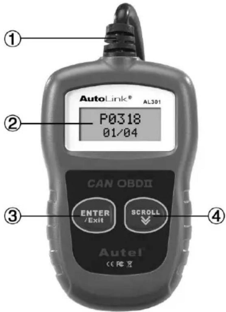
① OBD II CONNECTOR -- Connects the scan tool to the vehicle's Data Link Connector (DLC).
② LCD DISPLAY -- Indicates test results. Backlit, 128 x 64 pixel display.
③ ENTER/Exit BUTTON -- Confirms a selection (or action) from a menu. Or returns to previous menu.
④ SCROLL BUTTON –Scrolls through menu items or cancel an operation.
3.2 Specifications
1) Display: Backlit LCD, 2 lines, 8 characters each line.
2) Operating Temperature: 0 to 50°C (32 to 122 F°)
3) Storage Temperature: -20 to 70°C (-4 to 158 F°)
4) External Power: DC12V provided via the vehicle's battery
5) Dimensions:
Length
110 mm (4.33")
3.3 Product Features
1) Works with all 1996 and newer cars & light trucks that are OBDII compliant (including the CAN, VPW, PWM, ISO and KWP2000 protocols).
2) Reads and clears generic and manufacturer specific Diagnostic Trouble Codes (DTCs) and turns off check engine light.
3) Supports multiple trouble code requests: generic codes, pending codes and manufacturer's specific codes.
4) Reviews the emission readiness status of OBD monitors.
5) Retrieves VIN (Vehicle Identification No.) on 2002 and newer vehicles that support Mode 9.
6) Determines the malfunction indicator lamp (MIL) status.
7) Easy to use with one plug-in; Highly reliable and accurate.
8) Easy-to-read crystal-clear backlit 2-line LCD display.
9) Stand-alone unit with no need for an additional laptop computer to operate.
10) Small in size and conveniently fits in your palm.
11) Safely communicates with the on-board computer.
12) No batteries needed--powered via detachable OBD II cable.
3.4 Vehicle Coverage
The Autolink AL301 OBDII Scanner is specially designed to work with all OBD II compliant vehicles, including those equipped with next-generation protocol -- Control Area Network (CAN). It is required by EPA that all 1996 and newer vehicles (cars and light trucks) sold in the United States must be OBD II compliant and this includes all Domestic, Asian and European vehicles.
A small number of 1994 and 1995 model year gasoline vehicles are OBD II compliant. To verify if a 1994 or 1995 vehicle is OBD II compliant, check the Vehicle Emissions Control Information (VECI) Label which is located under the hood or by the radiator of most vehicles. If the vehicle is OBD II compliant, the label will designate “OBD II Certified”. Additionally, Government regulations mandate that all OBD II compliant vehicles must have a “common” sixteen-pin Data Link Connector (DLC).
For your vehicle to be OBD II compliant it must have a 16-pin DLC (Data Link Connector) under the dash and the Vehicle Emission Control Information Label must state that the vehicle is OBD II compliant.
4. Operating Instructions
4.1 Reading Codes
CAUTION: Don't connect or disconnect any test equipment with ignition on or engine running.
- Turn the ignition off.
- Locate the 16-pin Data Link Connector (DLC) and plug into the Scan Tool cable connector to the DLC.
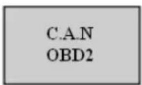
- Wait for the LCD display to read "C.A.N.OBD2".
-
Turn the ignition on. But do not start the engine.
-
Press the ENTER button. A sequence of messages showing the OBD2 protocols will be observed on the display until the vehicle protocol is detected.
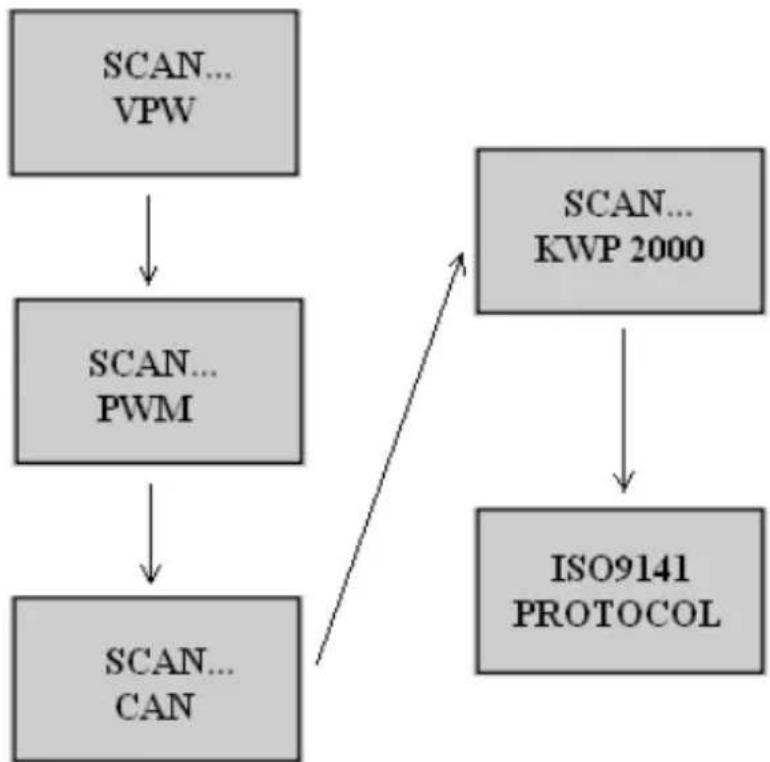
flowchart
graph TD
    A["SCAN... VPW"] --> B["SCAN... PWM"]
    B --> C["SCAN... CAN"]
    D["SCAN... KWP 2000"] --> E["ISO9141 PROTOCOL"]
    C --> E
- Not all the above messages will be displayed unless protocol of the vehicle being tested is the last one—the ISO9141 protocol. They will stop appearing after the vehicle protocol is detected and a confirmation message of “XXX Protocol” is displayed.
- If a “LINK ERROR!” message shows up, turn the ignition off for about 10 seconds, check if the Scan Tool’s OBDII connector is securely connected to the vehicle’s DLC, and then turn the ignition back to on. Repeat the procedure from step 5. If the “LINK ERROR” message does not go away, then there may be problems for the Scan Tool to communicate with the vehicle.
- Wait for the main menu to come up after a brief overview displaying the scanning results with the total number of DTCs and the overall I/M Monitor Status.
DTC: 02
IM: YES
- Select "DTC" from the main menu by pressing the ENTER button.
MENU:
- DTC
- If there are no Diagnostic Trouble Codes retrieved, the display will indicate “NO CODES”.
NO CODES
- If there are any Diagnostic Trouble Codes, then the total number of the Fault Codes followed by that of the Pending Codes will be reported on the display.
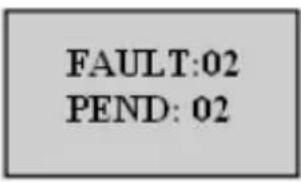
- Read the Diagnostic Trouble Codes by pressing the SCROLL button.
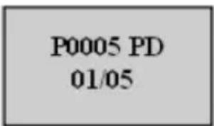
- The first code number will appear on the first line of the LCD display, the numerical sequence of the code and the total number of the codes stored will appear on the second line. To view additional codes, press the SCROLL button to scroll, as necessary, until all the codes have been shown up.

- If the code retrieved is a pending code, a “PD” will show on the LCD display in the end.
- To view previous codes, press the SCROLL button to scroll through to the end, and then start from the first of the list.
- Look up part 5 for Diagnostic Trouble Code Definitions. Match the retrieved DTC(S) with those listed and read the definitions.
4.2 Erasing Codes
CAUTION: Erasing the Diagnostic Trouble Codes allows the Scan Tool to delete not only the codes from the vehicle's on-board computer, but also “Freeze Frame” data and manufacturer specific enhanced data. Further, the I/M Readiness Monitor Status for all vehicle Monitors is reset to Not Ready or Not Complete status. Do not erase the codes before the system has been checked completely by a technician.
- If you decide to erase the DTCs, Select “2. ERASE” from the main menu by pressing the ENTER button.
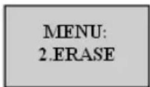
- If the Scan Tool is not connected or no communication is established with the vehicle yet, then refer to “Reading Codes” from 1 to 6 at Paragraph 4.1.
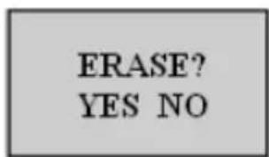
- A message of “ERASE? YES NO” comes up asking for your confirmation.
-
If you do not want to proceed with erasing the codes, SCROLL button to exit.
-
If you do wish to proceed to erase the codes, then press the ENTER button.
-
If the codes are cleared successfully, an “ERASE DONE!” message will show on the display. Press the ENTER button to return to the main Menu list.

- If the codes are not cleared, then an “ERASE FAIL!” message will appear. Press the ENTER button to return to the main Menu list.
ERASE FAIL!
HOT KEY: Pressing and Holding the SCROLL button for about 3 seconds will allow you to erase the DTCs more quickly than through the main menu.
IMPORTANT: I/M Readiness function is used to check the operations of the Emission System on OBD2 compliant vehicles. It is an excellent function to use prior to having a vehicle inspected for compliance to a state emissions program.
An I/M Readiness Status result of “NO” does not necessarily indicate that the vehicle being tested will fail the state I/M inspection. For some states, one or more such monitors may be allowed to be “Not Ready” to pass the emissions inspection.
“YES”--All monitors supported on the vehicle have completed their diagnostic testing and the MIL light is not on.\
“NO”--At least one monitor supported on the vehicle has not completed its diagnostic testing, and (or) the “Check Engine”(MIL) light is on.
“READY”—Indicates that a particular monitor being checked has completed its diagnostic testing.
"Not RDY(NOT READY)"—Indicates that a particular monitor being checked has not completed its diagnostic testing.
“N/A”—The monitor is not supported on that vehicle.
“→”-- A flashing Right Arrow indicates additional information is available on the next screen.
“←”-- A flashing Left Arrow indicates additional information is available on the previous screen.
- Select “3. I/M” from the main menu by pressing the ENTER button.
MENU:
- I/M
- If the Scan Tool is not connected yet, then refer to “Reading Codes” from 1 to 6 at Section 4.1.
- Use the SCROLL button to view the status of the MIL light (“ON” or “OFF) and the following monitors:
MISFIRE--Misfire monitor
FUEL--Fuel System Monitor
CCM--Comprehensive Components Monitor
CAT-- Catalyst Monitor
HCM--Heated Catalyst Monitor
EVAP-- Evaporative System Monitor
2AIR-- Secondary Air Monitor
A/C--A/C system Monitor
O2S-- O2 Sensors Monitor
HO2S--O2 Sensor Heater Monitor
EGR-- EGR System Monitor
- Press the ENTER button to return to the main Menu.
4.4 Viewing VIN Number
The View VIN function allows you to retrieve the Vehicle Identification No. on 2002 and newer vehicles that support Mode 9.
- Select "4. VIN" from the main menu by pressing the ENTER Button.
MENU:
- VIN
- If the Scan Tool is not connected yet, then refer to “Reading Codes” from step 1 to 6 at Section 4.1.
- Use the SCROLL button to view additional digits of the 17-digit string.
“→” -- A flashing Right Arrow indicates additional digits of VIN string are available on the next screen.
“←”-- A flashing Left Arrow indicates additional digits of VIN string are available on the previous screen.
- Press the ENTER button to return to the main Menu.
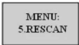
4.5 Rescanning Data
The RESCAN function allows you to retrieve the most current data stored in the ECM or to re-link to the vehicle if communication is disconnected.
- Select “5. RESCAN” from the main menu by pressing the ENTER button.
- If the Scan Tool is not connected yet, then refer to “Reading Codes” from 1 to 6 at Section 4.1.
- Use either the SCROLL or ENTER button to return to the main menu.
5. Warranty and Service
5.1. Limited One Year Warranty
Autel warrants to its customers that this product will be free from all defects in materials and workmanship for a period of one (1) year from the date of the original purchase, subject to the following terms and conditions:
1) The sole responsibility of Autel under the Warranty is limited to either the repair or, at the option of Autel, replacement of the Scan Tool at no charge with Proof of Purchase. The sales receipt may be used for this purpose.
2) This warranty does not apply to damages caused by improper use, accident, flood, lightning, or if the product was altered or repaired by anyone other than the Manufacturer's Service Center.
3) Autel shall not be liable for any incidental or consequential damages arising from the use, misuse, or mounting of the Scan Tool. Some states do not allow limitations on how long an implied warranty lasts, so the above limitations may not apply to you.
5.2. Service Procedures
If you have any questions, please contact your local store, distributor or visit our website at www.auteltech.com.
If it becomes necessary to return the Scan Tool for repair, contact your local distributor for more information.
6. Diagnostic Trouble Code (DTC) Definitions
The following Diagnostic Trouble Code Definitions lists provide only Generic Diagnostic Trouble Codes. For Manufacturer Specific Diagnostic Trouble Code Definitions, consult the vehicle's service manual or the enclosed CD software.
CAUTION: Parts or components should not be replaced based on only a DTC without first consulting the vehicle service manual for more information on possible causes of the fault as well as required testing procedures.
OBDII Generic DTC Definitions
| DTC | Definition |
| P0001 | Fuel Volume Regulator Control Circuit/Open |
| P0002 | Fuel Volume Regulator Control Circuit Range/Performance |
| P0003 | Fuel Volume Regulator Control Circuit Low |
| P0004 | Fuel Volume Regulator Control Circuit High |
| P0005 | Fuel Shutoff Valve "A" Control Circuit/Open |
| P0006 | Fuel Shutoff Valve "A" Control Circuit Low |
| P0007 | Fuel Shutoff Valve "A" Control Circuit High |
| P0008 | Engine Position System Performance Bank 1 |
| P0009 | Engine Position System Performance Bank 2 |
| P000A | "A" Camshaft Position Slow Response Bank 1 |
| P000B | "B" Camshaft Position Slow Response Bank 1 |
| P000C | "A" Camshaft Position Slow Response Bank 2 |
| P000D | "B" Camshaft Position Slow Response Bank 2 |
| P000E | Fuel Volume Regulator Control Exceeded Learning Limit |
| P000F | Fuel System Over Pressure Relief Valve Activated |
| P0010 | "A" Camshaft Position Actuator Circuit/Open Bank 1 |
| P0011 | "A" Camshaft Position - Timing Over-Advanced or System Performance Bank 1 |
| P0012 | "A" Camshaft Position - Timing Over-Retarded Bank 1 |
| P0013 | "B" Camshaft Position - Actuator Circuit/Open Bank 1 |
| P0014 | "B" Camshaft Position - Timing Over-Advanced or System Performance Bank 1 |
| P0015 | "B" Camshaft Position - Timing Over-Retarded Bank 1 |
| P0016 | Crankshaft Position - Camshaft Position Correlation Bank 1 Sensor A |
| P0017 | Crankshaft Position - Camshaft Position Correlation Bank 1 Sensor B |
| P0018 | Crankshaft Position - Camshaft Position Correlation Bank 2 Sensor A |
| P0019 | Crankshaft Position - Camshaft Position Correlation Bank 2 Sensor B |
| P001A | "A" Camshaft Profile Control Circuit/Open Bank 1 |
| P001B | "A" Camshaft Profile Control Circuit Low Bank 1 |
| P001C | "A" Camshaft Profile Control Circuit High Bank 1 |
| P001D | "A" Camshaft Profile Control Circuit/Open Bank 2 |
| P001E | "A" Camshaft Profile Control Circuit Low Bank 2 |
| P001F | "A" Camshaft Profile Control Circuit High Bank 2 |
| P0020 | "A" Camshaft Position Actuator Circuit/Open Bank 2 |
| P0021 | "A" Camshaft Position - Timing Over-Advanced or System Performance Bank 2 |
| P0022 | "A" Camshaft Position - Timing Over-Retarded Bank 2 |
| P0023 | "B" Camshaft Position - Actuator Circuit/Open Bank 2 |
| P0024 | "B" Camshaft Position - Timing Over-Advanced or System Performance Bank 2 |
| P0025 | "B" Camshaft Position - Timing Over-Retarded Bank 2 |
| P0026 | Intake Valve Control Solenoid Circuit Range/Performance Bank 1 |
| P0027 | Exhaust Valve Control Solenoid Circuit Range/Performance Bank 1 |
| P0028 | Intake Valve Control Solenoid Circuit Range/Performance Bank 2 |
| P0029 | Exhaust Valve Control Solenoid Circuit Range/Performance Bank 2 |
| P002A | "B" Camshaft Profile Control Circuit/Open Bank 1 |
| P002B | "B" Camshaft Profile Control Circuit Low Bank 1 |
| P002C | "B" Camshaft Profile Control Circuit High Bank 1 |
| P002D | "B" Camshaft Profile Control Circuit/Open Bank 2 |
| P002E | "B" Camshaft Profile Control Circuit Low Bank 2 |
| P002F | "B" Camshaft Profile Control Circuit High Bank 2 |
| P0030 | HO2S Heater Control Circuit Bank 1 Sensor 1 |
| P0031 | HO2S Heater Control Circuit Low Bank 1 Sensor 1 |
| P0032 | HO2S Heater Control Circuit High Bank 1 Sensor 1 |
| P0033 | Turbocharger/Supercharger Bypass Valve Control Circuit |
| P0034 | Turbocharger/Supercharger Bypass Valve Control Circuit Low |
| P0035 | Turbocharger/Supercharger Bypass Valve Control Circuit High |
| P0036 | HO2S Heater Control Circuit Bank 1 Sensor 2 |
| P0037 | HO2S Heater Control Circuit Low Bank 1 Sensor 2 |
| P0038 | HO2S Heater Control Circuit High Bank 1 Sensor 2 |
| P0039 | Turbocharger/Supercharger Bypass Valve Control Circuit Range/Performance |
| P003A | Turbocharger/Supercharger Boost Control "A" Position Exceeded Learning Limit |
| P003B | Turbocharger/Supercharger Boost Control "B" Position Exceeded Learning Limit |
| P003C | "A" Camshaft Profile Control Performance/Stuck Off Bank 1 |
| P003D | "A" Camshaft Profile Control Stuck On Bank 1 |
| P003E | "A" Camshaft Profile Control Performance/Stuck Off Bank 2 |
| P003F | "A" Camshaft Profile Control Stuck On Bank 2 |
| P0040 | O2 Sensor Signals Swapped Bank 1 Sensor 1/Bank 2 Sensor 1 |
| P0041 | O2 Sensor Signals Swapped Bank 1 Sensor 2/Bank 2 Sensor 2 |
| P0042 | HO2S Heater Control Circuit Bank 1 Sensor 3 |
| P0043 | HO2S Heater Control Circuit Low Bank 1 Sensor 3 |
| P0044 | HO2S Heater Control Circuit High Bank 1 Sensor 3 |
| P0045 | Turbocharger/Supercharger Boost Control "A" Circuit/Open |
| P0046 | Turbocharger/Supercharger Boost Control "A" Circuit Range/Performance |
| P0047 | Turbocharger/Supercharger Boost Control "A" Circuit Low |
| P0048 | Turbocharger/Supercharger Boost Control "A" Circuit High |
| P0049 | Turbocharger/Supercharger Turbine Overspeed |
| P004A | Turbocharger/Supercharger Boost Control "B" Circuit/Open |
| P004B | Turbocharger/Supercharger Boost Control "B" Circuit Range/Performance |
| P004C | Turbocharger/Supercharger Boost Control "B" Circuit Low |
| P004D | Turbocharger/Supercharger Boost Control "B" Circuit High |
| P004E | Turbocharger/Supercharger Boost Control "A" Circuit Intermittent/Erratic |
| P004F | Turbocharger/Supercharger Boost Control "B" Circuit Intermittent/Erratic |
| P0050 | HO2S Heater Control Circuit Bank 2 Sensor 1 |
| P0051 | HO2S Heater Control Circuit Low Bank 2 Sensor 1 |
| P0052 | HO2S Heater Control Circuit High Bank 2 Sensor 1 |
| P0053 | HO2S Heater Resistance Bank 1 Sensor 1 |
| P0054 | HO2S Heater Resistance Bank 1 Sensor 2 |
| P0055 | HO2S Heater Resistance Bank 1 Sensor 3 |
| P0056 | HO2S Heater Control Circuit Bank 2 Sensor 2 |
| P0057 | HO2S Heater Control Circuit Low Bank 2 Sensor 2 |
| P0058 | HO2S Heater Control Circuit High Bank 2 Sensor 2 |
| P0059 | HO2S Heater Resistance Bank 2 Sensor 1 |
| P005A | "B" Camshaft Profile Control Performance/Stuck Off Bank 1 |
| P005B | "B" Camshaft Profile Control Stuck On Bank 1 |
| P005C | "B" Camshaft Profile Control Performance/Stuck Off Bank 2 |
| P005D | "B" Camshaft Profile Control Stuck On Bank 2 |
| P005E | Turbocharger/Supercharger Boost Control "B" Supply Voltage Circuit Low |
| P005F | Turbocharger/Supercharger Boost Control "B" Supply Voltage Circuit High |
| P0060 | HO2S Heater Resistance Bank 2 Sensor 2 |
| P0061 | HO2S Heater Resistance Bank 2 Sensor 3 |
| P0062 | HO2S Heater Control Circuit Bank 2 Sensor 3 |
| P0063 | HO2S Heater Control Circuit Low Bank 2 Sensor 3 |
| P0064 | HO2S Heater Control Circuit High Bank 2 Sensor 3 |
| P0065 | Air Assisted Injector Control Range/Performance |
| P0066 | Air Assisted Injector Control Circuit or Circuit Low |
| P0067 | Air Assisted Injector Control Circuit High |
| P0068 | MAP/MAF - Throttle Position Correlation |
| P0069 | Manifold Absolute Pressure - Barometric Pressure Correlation |
| P006A | MAP - Mass or Volume Air Flow Correlation Bank 1 |
| P006B | MAP - Exhaust Pressure Correlation |
| P006C | MAP - Turbocharger/Supercharger Inlet Pressure Correlation |
| P006D | Barometric Pressure - Turbocharger/Supercharger Inlet Pressure Correlation |
| P006E | Turbocharger/Supercharger Boost Control "A" Supply Voltage Circuit Low |
| P006F | Turbocharger/Supercharger Boost Control "A" Supply Voltage Circuit High |
| P0070 | Ambient Air Temperature Sensor Circuit |
| P0071 | Ambient Air Temperature Sensor Range/Performance |
| P0072 | Ambient Air Temperature Sensor Circuit Low |
| P0073 | Ambient Air Temperature Sensor Circuit High |
| P0074 | Ambient Air Temperature Sensor Circuit Intermittent |
| P0075 | Intake Valve Control Solenoid Circuit Bank 1 |
| P0076 | Intake Valve Control Solenoid Circuit Low Bank 1 |
| P0077 | Intake Valve Control Solenoid Circuit High Bank 1 |
| P0078 | Exhaust Valve Control Solenoid Circuit Bank 1 |
| P0079 | Exhaust Valve Control Solenoid Circuit Low Bank 1 |
| P007A | Charge Air Cooler Temperature Sensor Circuit Bank 1 |
| P007B | Charge Air Cooler Temperature Sensor Circuit Range/Performance Bank 1 |
| P007C | Charge Air Cooler Temperature Sensor Circuit Low Bank 1 |
| P007D | Charge Air Cooler Temperature Sensor Circuit High Bank 1 |
| P007E | Charge Air Cooler Temperature Sensor Circuit Intermittent/Erratic Bank 1 |
| P007F | Charge Air Cooler Temperature Sensor Bank1/Bank2 Correlation |
| P0080 | Exhaust Valve Control Solenoid Circuit High Bank 1 |
| P0081 | Intake Valve Control Solenoid Circuit Bank 2 |
| P0082 | Intake Valve Control Solenoid Circuit Low Bank 2 |
| P0083 | Intake Valve Control Solenoid Circuit High Bank 2 |
| P0084 | Exhaust Valve Control Solenoid Circuit Bank 2 |
| P0085 | Exhaust Valve Control Solenoid Circuit Low Bank 2 |
| P0086 | Exhaust Valve Control Solenoid Circuit High Bank 2 |
| P0087 | Fuel Rail/System Pressure - Too Low |
| P0088 | Fuel Rail/System Pressure - Too High |
| P0089 | Fuel Pressure Regulator 1 Performance |
| P008A | Low Pressure Fuel System Pressure - Too Low |
| P008B | Low Pressure Fuel System Pressure - Too High |
| P008C | Fuel Cooler Pump Control Circuit/Open |
| P008D | Fuel Cooler Pump Control Circuit Low |
| P008E | Fuel Cooler Pump Control Circuit High |
| P008F | Engine Coolant Temperature/Fuel Temperature Correlation |
| P0090 | Fuel Pressure Regulator 1 Control Circuit/Open |
| P0091 | Fuel Pressure Regulator 1 Control Circuit Low |
| P0092 | Fuel Pressure Regulator 1 Control Circuit High |
| P0093 | Fuel System Leak Detected - Large Leak |
| P0094 | Fuel System Leak Detected - Small Leak |
| P0095 | Intake Air Temperature Sensor 2 Circuit Bank 1 |
| P0096 | Intake Air Temperature Sensor 2 Circuit Range/Performance Bank 1 |
| P0097 | Intake Air Temperature Sensor 2 Circuit Low Bank 1 |
| P0098 | Intake Air Temperature Sensor 2 Circuit High Bank 1 |
| P0099 | Intake Air Temperature Sensor 2 Circuit Intermittent/Erratic Bank 1 |
| P009A | Intake Air Temperature/Ambient Air Temperature Correlation |
| P009B | Fuel Pressure Relief Control Circuit/Open |
| P009C | Fuel Pressure Relief Control Circuit Low |
| P009D | Fuel Pressure Relief Control Circuit High |
| P009E | Fuel Pressure Relief Control Performance/Stuck Off |
| P009F | Fuel Pressure Relief Control Stuck On |
| P00A0 | Charge Air Cooler Temperature Sensor Circuit Bank 2 |
| P00A1 | Charge Air Cooler Temperature Sensor Circuit Range/Performance Bank 2 |
| P00A2 | Charge Air Cooler Temperature Sensor Circuit Low Bank 2 |
| P00A3 | Charge Air Cooler Temperature Sensor Circuit High Bank 2 |
| P00A4 | Charge Air Cooler Temperature Sensor Circuit Intermittent/Erratic Bank 2 |
| P00A5 | Intake Air Temperature Sensor 2 Circuit Bank 2 |
| P00A6 | Intake Air Temperature Sensor 2 Circuit Range/Performance Bank 2 |
| P00A7 | Intake Air Temperature Sensor 2 Circuit Low Bank 2 |
| P00A8 | Intake Air Temperature Sensor 2 Circuit High Bank 2 |
| P00A9 | Intake Air Temperature Sensor 2 Circuit Intermittent/Erratic Bank 2 |
| P00AA | Intake Air Temperature Sensor 1 Circuit Bank 2 |
| P00AB | Intake Air Temperature Sensor 1 Circuit Range/Performance Bank 2 |
| P00AC | Intake Air Temperature Sensor 1 Circuit Low Bank 2 |
| P00AD | Intake Air Temperature Sensor 1 Circuit High Bank 2 |
| P00AE | Intake Air Temperature Sensor 1 Circuit Intermittent Bank 2 |
| P00AF | Turbocharger/Supercharger Boost Control "A" Module Performance |
| P00B0 | Turbocharger/Supercharger Boost Control "B" Module Performance |
| P00B1 | Radiator Coolant Temperature Sensor Circuit |
| P00B2 | Radiator Coolant Temperature Sensor Circuit Range/Performance |
| P00B3 | Radiator Coolant Temperature Sensor Circuit Low |
| P00B4 | Radiator Coolant Temperature Sensor Circuit High |
| P00B5 | Radiator Coolant Temperature Sensor Circuit Intermittent/Erratic |
| P00B6 | Radiator Coolant Temperature/Engine Coolant Temperature Correlation |
| P00B7 | Engine Coolant Flow Low/Performance |
| P00B8 | MAP - Mass or Volume Air Flow Correlation Bank 2 |
| P00B9 | Low Pressure Fuel System Pressure - Too Low, Low Ambient Temperature |
| P00BA | Low Fuel Pressure - Forced Limited Power |
| P00BB | Fuel Injector Insufficient Flow - Forced Limited Power |
| P00BC | Mass or Volume Air Flow "A" Circuit Range/Performance - Air Flow Too Low |
| P00BD | Mass or Volume Air Flow "A" Circuit Range/Performance - Air Flow Too High |
| P00BE | Mass or Volume Air Flow "B" Circuit Range/Performance - Air Flow Too Low |
| P00BF | Mass or Volume Air Flow "B" Circuit Range/Performance - Air Flow Too High |
| P0100 | Mass or Volume Air Flow "A" Circuit |
| P0101 | Mass or Volume Air Flow "A" Circuit Range/Performance |
| P0102 | Mass or Volume Air Flow "A" Circuit Low |
| P0103 | Mass or Volume Air Flow "A" Circuit High |
| P0104 | Mass or Volume Air Flow "A" Circuit Intermittent |
| P0105 | Manifold Absolute Pressure/Barometric Pressure Circuit |
| P0106 | Manifold Absolute Pressure/Barometric Pressure Circuit Range/Performance |
| P0107 | Manifold Absolute Pressure/Barometric Pressure Circuit Low |
| P0108 | Manifold Absolute Pressure/Barometric Pressure Circuit High |
| P0109 | Manifold Absolute Pressure/Barometric Pressure Circuit Intermittent |
| P010A | Mass or Volume Air Flow "B" Circuit |
| P010B | Mass or Volume Air Flow "B" Circuit Range/Performance |
| P010C | Mass or Volume Air Flow "B" Circuit Low |
| P010D | Mass or Volume Air Flow "B" Circuit High |
| P010E | Mass or Volume Air Flow "B" Circuit Intermittent/Erratic |
| P010F | Mass or Volume Air Flow Sensor A/B Correlation |
| P0110 | Intake Air Temperature Sensor 1 Circuit Bank 1 |
| P0111 | Intake Air Temperature Sensor 1 Circuit Range/Performance Bank 1 |
| P0112 | Intake Air Temperature Sensor 1 Circuit Low Bank 1 |
| P0113 | Intake Air Temperature Sensor 1 Circuit High Bank 1 |
| P0114 | Intake Air Temperature Sensor 1 Circuit Intermittent Bank 1 |
| P0115 | Engine Coolant Temperature Sensor 1 Circuit |
| P0116 | Engine Coolant Temperature Sensor 1 Circuit Range/Performance |
| P0117 | Engine Coolant Temperature Sensor 1 Circuit Low |
| P0118 | Engine Coolant Temperature Sensor 1 Circuit High |
| P0119 | Engine Coolant Temperature Sensor 1 Circuit Intermittent |
| P011A | Engine Coolant Temperature Sensor 1/2 Correlation |
| P011B | Engine Coolant Temperature/Intake Air Temperature Correlation |
| P011C | Charge Air Temperature/Intake Air Temperature Correlation Bank 1 |
| P011D | Charge Air Temperature/Intake Air Temperature Correlation Bank 2 |
| P0120 | Throttle/Pedal Position Sensor/Switch "A" Circuit |
| P0121 | Throttle/Pedal Position Sensor/Switch "A" Circuit Range/Performance |
| P0122 | Throttle/Pedal Position Sensor/Switch "A" Circuit Low |
| P0123 | Throttle/Pedal Position Sensor/Switch "A" Circuit High |
| P0124 | Throttle/Pedal Position Sensor/Switch "A" Circuit Intermittent |
| P0125 | Insufficient Coolant Temperature for Closed Loop Fuel Control |
| P0126 | Insufficient Coolant Temperature for Stable Operation |
| P0127 | Intake Air Temperature Too High |
| P0128 | Coolant Thermostat (Coolant Temperature Below Thermostat Regulating Temperature) |
| P0129 | Barometric Pressure Too Low |
| P012A | Turbocharger/Supercharger Inlet Pressure Sensor Circuit Downstream of throttle valve |
| P012B | Turbocharger/Supercharger Inlet Pressure Sensor Circuit Range/Performance Downstream of throttle valve |
| P012C | Turbocharger/Supercharger Inlet Pressure Sensor Circuit Low Downstream of throttle valve |
| P012D | Turbocharger/Supercharger Inlet Pressure Sensor Circuit High Downstream of throttle valve |
| P012E | Turbocharger/Supercharger Inlet Pressure Sensor Circuit Intermittent/Erratic Downstream of throttle valve |
| P0130 | O2 Sensor Circuit Bank 1 Sensor 1 |
| P0131 | O2 Sensor Circuit Low Voltage Bank 1 Sensor 1 |
| P0132 | O2 Sensor Circuit High Voltage Bank 1 Sensor 1 |
| P0133 | O2 Sensor Circuit Slow Response Bank 1 Sensor 1 |
| P0134 | O2 Sensor Circuit No Activity Detected Bank 1 Sensor 1 |
| P0135 | O2 Sensor Heater Circuit Bank 1 Sensor 1 |
| P0136 | O2 Sensor Circuit Bank 1 Sensor 2 |
| P0137 | O2 Sensor Circuit Low Voltage Bank 1 Sensor 2 |
| P0138 | O2 Sensor Circuit High Voltage Bank 1 Sensor 2 |
| P0139 | O2 Sensor Circuit Slow Response Bank 1 Sensor 2 |
| P013A | O2 Sensor Slow Response - Rich to Lean Bank 1 Sensor 2 |
| P013B | O2 Sensor Slow Response - Lean to Rich Bank 1 Sensor 2 |
| P013C | O2 Sensor Slow Response - Rich to Lean Bank 2 Sensor 2 |
| P013D | O2 Sensor Slow Response - Lean to Rich Bank 2 Sensor 2 |
| P013E | O2 Sensor Delayed Response - Rich to Lean Bank 1 Sensor 2 |
| P013F | O2 Sensor Delayed Response - Lean to Rich Bank 1 Sensor 2 |
| P0140 | O2 Sensor Circuit No Activity Detected Bank 1 Sensor 2 |
| P0141 | O2 Sensor Heater Circuit Bank 1 Sensor 2 |
| P0142 | O2 Sensor Circuit Bank 1 Sensor 3 |
| P0143 | O2 Sensor Circuit Low Voltage Bank 1 Sensor 3 |
| P0144 | O2 Sensor Circuit High Voltage Bank 1 Sensor 3 |
| P0145 | O2 Sensor Circuit Slow Response Bank 1 Sensor 3 |
| P0146 | O2 Sensor Circuit No Activity Detected Bank 1 Sensor 3 |
| P0147 | O2 Sensor Heater Circuit Bank 1 Sensor 3 |
| P0148 | Fuel Delivery Error |
| P0149 | Fuel Timing Error |
| P014A | O2 Sensor Delayed Response - Rich to Lean Bank 2 Sensor 2 |
| P014B | O2 Sensor Delayed Response - Lean to Rich Bank 2 Sensor 2 |
| P014C | O2 Sensor Slow Response - Rich to Lean Bank 1 Sensor 1 |
| P014D | O2 Sensor Slow Response - Lean to Rich Bank 1 Sensor 1 |
| P014E | O2 Sensor Slow Response - Rich to Lean Bank 2 Sensor 1 |
| P014F | O2 Sensor Slow Response - Lean to Rich Bank 2 Sensor 1 |
| P0150 | O2 Sensor Circuit Bank 2 Sensor 1 |
| P0151 | O2 Sensor Circuit Low Voltage Bank 2 Sensor 1 |
| P0152 | O2 Sensor Circuit High Voltage Bank 2 Sensor 1 |
| P0153 | O2 Sensor Circuit Slow Response Bank 2 Sensor 1 |
| P0154 | O2 Sensor Circuit No Activity Detected Bank 2 Sensor 1 |
| P0155 | O2 Sensor Heater Circuit Bank 2 Sensor 1 |
| P0156 | O2 Sensor Circuit Bank 2 Sensor 2 |
| P0157 | O2 Sensor Circuit Low Voltage Bank 2 Sensor 2 |
| P0158 | O2 Sensor Circuit High Voltage Bank 2 Sensor 2 |
| P0159 | O2 Sensor Circuit Slow Response Bank 2 Sensor 2 |
| P015A | O2 Sensor Delayed Response - Rich to Lean Bank 1 Sensor 1 |
| P015B | O2 Sensor Delayed Response - Lean to Rich Bank 1 Sensor 1 |
| P015C | O2 Sensor Delayed Response - Rich to Lean Bank 2 Sensor 1 |
| P015D | O2 Sensor Delayed Response - Lean to Rich Bank 2 Sensor 1 |
| P0160 | O2 Sensor Circuit No Activity Detected Bank 2 Sensor 2 |
| P0161 | O2 Sensor Heater Circuit Bank 2 Sensor 2 |
| P0162 | O2 Sensor Circuit Bank 2 Sensor 3 |
| P0163 | O2 Sensor Circuit Low Voltage Bank 2 Sensor 3 |
| P0164 | O2 Sensor Circuit High Voltage Bank 2 Sensor 3 |
| P0165 | O2 Sensor Circuit Slow Response Bank 2 Sensor 3 |
| P0166 | O2 Sensor Circuit No Activity Detected Bank 2 Sensor 3 |
| P0167 | O2 Sensor Heater Circuit Bank 2 Sensor 3 |
| P0168 | Fuel Temperature Too High |
| P0169 | Incorrect Fuel Composition |
| P0170 | Fuel Trim Bank 1 |
| P0171 | System Too Lean Bank 1 |
| P0172 | System Too Rich Bank 1 |
| P0173 | Fuel Trim Bank 2 |
| P0174 | System Too Lean Bank 2 |
| P0175 | System Too Rich Bank 2 |
| P0176 | Fuel Composition Sensor Circuit |
| P0177 | Fuel Composition Sensor Circuit Range/Performance |
| P0178 | Fuel Composition Sensor Circuit Low |
| P0179 | Fuel Composition Sensor Circuit High |
| P0180 | Fuel Temperature Sensor "A" Circuit |
| P0181 | Fuel Temperature Sensor "A" Circuit Range/Performance |
| P0182 | Fuel Temperature Sensor "A" Circuit Low |
| P0183 | Fuel Temperature Sensor "A" Circuit High |
| P0184 | Fuel Temperature Sensor "A" Circuit Intermittent |
| P0185 | Fuel Temperature Sensor "B" Circuit |
| P0186 | Fuel Temperature Sensor "B" Circuit Range/Performance |
| P0187 | Fuel Temperature Sensor "B" Circuit Low |
| P0188 | Fuel Temperature Sensor "B" Circuit High |
| P0189 | Fuel Temperature Sensor "B" Circuit Intermittent |
| P018A | Fuel Pressure Sensor "B" Circuit |
| P018B | Fuel Pressure Sensor "B" Circuit Range/Performance |
| P018C | Fuel Pressure Sensor "B" Circuit Low |
| P018D | Fuel Pressure Sensor "B" Circuit High |
| P018E | Fuel Pressure Sensor "B" Circuit Intermittent/Erratic |
| P018F | Fuel System Over Pressure Relief Valve Frequent Activation |
| P0190 | Fuel Rail Pressure Sensor "A" Circuit |
| P0191 | Fuel Rail Pressure Sensor "A" Circuit Range/Performance |
| P0192 | Fuel Rail Pressure Sensor "A" Circuit Low |
| P0193 | Fuel Rail Pressure Sensor "A" Circuit High |
| P0194 | Fuel Rail Pressure Sensor "A" Circuit Intermittent/Erratic |
| P0195 | Engine Oil Temperature Sensor Circuit |
| P0196 | Engine Oil Temperature Sensor Range/Performance |
| P0197 | Engine Oil Temperature Sensor Circuit Low |
| P0198 | Engine Oil Temperature Sensor Circuit High |
| P0199 | Engine Oil Temperature Sensor Circuit Intermittent/Erratic |
| P0200 | Injector Circuit/Open |
| P0201 | Injector Circuit/Open - Cylinder 1 |
| P0202 | Injector Circuit/Open - Cylinder 2 |
| P0203 | Injector Circuit/Open - Cylinder 3 |
| P0204 | Injector Circuit/Open - Cylinder 4 |
| P0205 | Injector Circuit/Open - Cylinder 5 |
| P0206 | Injector Circuit/Open - Cylinder 6 |
| P0207 | Injector Circuit/Open - Cylinder 7 |
| P0208 | Injector Circuit/Open - Cylinder 8 |
| P0209 | Injector Circuit/Open - Cylinder 9 |
| P020A | Cylinder 1 Injection Timing |
| P020B | Cylinder 2 Injection Timing |
| P020C | Cylinder 3 Injection Timing |
| P020D | Cylinder 4 Injection Timing |
| P020E | Cylinder 5 Injection Timing |
| P020F | Cylinder 6 Injection Timing |
| P0210 | Injector Circuit/Open - Cylinder 10 |
| P0211 | Injector Circuit/Open - Cylinder 11 |
| P0212 | Injector Circuit/Open - Cylinder 12 |
| P0213 | Cold Start Injector 1 |
| P0214 | Cold Start Injector 2 |
| P0215 | Engine Shutoff Solenoid |
| P0216 | Injector/Injection Timing Control Circuit |
| P0217 | Engine Coolant Over Temperature Condition |
| P0218 | Transmission Fluid Over Temperature Condition |
| P0219 | Engine Overspeed Condition |
| P021A | Cylinder 7 Injection Timing |
| P021B | Cylinder 8 Injection Timing |
| P021C | Cylinder 9 Injection Timing |
| P021D | Cylinder 10 Injection Timing |
| P021E | Cylinder 11 Injection Timing |
| P021F | Cylinder 12 Injection Timing |
| P0220 | Throttle/Pedal Position Sensor/Switch "B" Circuit |
| P0221 | Throttle/Pedal Position Sensor/Switch "B" CircuitRange/Performance |
| P0222 | Throttle/Pedal Position Sensor/Switch "B" Circuit Low |
| P0223 | Throttle/Pedal Position Sensor/Switch "B" Circuit High |
| P0224 | Throttle/Pedal Position Sensor/Switch "B" Circuit Intermittent |
| P0225 | Throttle/Pedal Position Sensor/Switch "C" Circuit |
| P0226 | Throttle/Pedal Position Sensor/Switch "C" Circuit Range/Performance |
| P0227 | Throttle/Pedal Position Sensor/Switch "C" Circuit Low |
| P0228 | Throttle/Pedal Position Sensor/Switch "C" Circuit High |
| P0229 | Throttle/Pedal Position Sensor/Switch "C" Circuit Intermittent |
| P022A | Charge Air Cooler Bypass Control "A" Circuit /Open |
| P022B | Charge Air Cooler Bypass Control "A" Circuit Low |
| P022C | Charge Air Cooler Bypass Control "A" Circuit High |
| P022D | Charge Air Cooler Bypass Control "B" Circuit /Open |
| P022E | Charge Air Cooler Bypass Control "B" Circuit Low |
| P022F | Charge Air Cooler Bypass Control "B" Circuit High |
| P0230 | Fuel Pump Primary Circuit |
| P0231 | Fuel Pump Secondary Circuit Low |
| P0232 | Fuel Pump Secondary Circuit High |
| P0233 | Fuel Pump Secondary Circuit Intermittent |
| P0234 | Turbocharger/Supercharger "A" Overboost Condition |
| P0235 | Turbocharger/Supercharger Boost Sensor "A" Circuit |
| P0236 | Turbocharger/Supercharger Boost Sensor "A" Circuit Range/Performance |
| P0237 | Turbocharger/Supercharger Boost Sensor "A" Circuit Low |
| P0238 | Turbocharger/Supercharger Boost Sensor "A" Circuit High |
| P0239 | Turbocharger/Supercharger Boost Sensor "B" Circuit |
| P023A | Charge Air Cooler Coolant Pump Control Circuit/Open |
| P023B | Charge Air Cooler Coolant Pump Control Circuit Low |
| P023C | Charge Air Cooler Coolant Pump Control Circuit High |
| P023D | Manifold Absolute Pressure - Turbocharger/Supercharger Boost Sensor "A" Correlation |
| P023E | Manifold Absolute Pressure - Turbocharger/Supercharger Boost Sensor "B" Correlation |
| P023F | Fuel Pump Secondary Circuit/Open |
| P0240 | Turbocharger/Supercharger Boost Sensor "B" Circuit Range/Performance |
| P0241 | Turbocharger/Supercharger Boost Sensor "B" Circuit Low |
| P0242 | Turbocharger/Supercharger Boost Sensor "B" Circuit High |
| P0243 | Turbocharger/Supercharger Wastegate Solenoid "A" |
| P0244 | Turbocharger/Supercharger Wastegate Solenoid "A" Range/Performance |
| P0245 | Turbocharger/Supercharger Wastegate Solenoid "A" Low |
| P0246 | Turbocharger/Supercharger Wastegate Solenoid "A" High |
| P0247 | Turbocharger/Supercharger Wastegate Solenoid "B" |
| P0248 | Turbocharger/Supercharger Wastegate Solenoid "B" Range/Performance |
| P0249 | Turbocharger/Supercharger Wastegate Solenoid "B" Low |
| P024A | Charge Air Cooler Bypass Control "A" Range/Performance |
| P024B | Charge Air Cooler Bypass Control "A" Stuck |
| P024C | Charge Air Cooler Bypass Position Sensor "A" Circuit |
| P024D | Charge Air Cooler Bypass Position Sensor "A" Circuit Range/Performance |
| P024E | Charge Air Cooler Bypass Position Sensor "A" Circuit Low |
| P024F | Charge Air Cooler Bypass Position Sensor "A" Circuit High |
| P0250 | Turbocharger/Supercharger Wastegate Solenoid "B" High |
| P0251 | Injection Pump Fuel Metering Control "A" (Cam/Rotor/Injector) |
| P0252 | Injection Pump Fuel Metering Control "A" Range/Performance (Cam/Rotor/Injector) |
| P0253 | Injection Pump Fuel Metering Control "A" Low (Cam/Rotor/Injector) |
| P0254 | Injection Pump Fuel Metering Control "A" High (Cam/Rotor/Injector) |
| P0255 | Injection Pump Fuel Metering Control "A" Intermittent (Cam/Rotor/Injector) |
| P0256 | Injection Pump Fuel Metering Control "B" (Cam/Rotor/Injector) |
| P0257 | Injection Pump Fuel Metering Control "B" Range/Performance (Cam/Rotor/Injector) |
| P0258 | Injection Pump Fuel Metering Control "B" Low (Cam/Rotor/Injector) |
| P0259 | Injection Pump Fuel Metering Control "B" High (Cam/Rotor/Injector) |
| P025A | Fuel Pump Module Control Circuit/Open |
| P025B | Fuel Pump Module Control Circuit Range/Performance |
| P025C | Fuel Pump Module Control Circuit Low |
| P025D | Fuel Pump Module Control Circuit High |
| P0260 | Injection Pump Fuel Metering Control "B" Intermittent (Cam/Rotor/Injector) |
| P0261 | Cylinder 1 Injector Circuit Low |
| P0262 | Cylinder 1 Injector Circuit High |
| P0263 | Cylinder 1 Contribution/Balance |
| P0264 | Cylinder 2 Injector Circuit Low |
| P0265 | Cylinder 2 Injector Circuit High |
| P0266 | Cylinder 2 Contribution/Balance |
| P0267 | Cylinder 3 Injector Circuit Low |
| P0268 | Cylinder 3 Injector Circuit High |
| P0269 | Cylinder 3 Contribution/Balance |
| P0270 | Cylinder 4 Injector Circuit Low |
| P0271 | Cylinder 4 Injector Circuit High |
| P0272 | Cylinder 4 Contribution/Balance |
| P0273 | Cylinder 5 Injector Circuit Low |
| P0274 | Cylinder 5 Injector Circuit High |
| P0275 | Cylinder 5 Contribution/Balance |
| P0276 | Cylinder 6 Injector Circuit Low |
| P0277 | Cylinder 6 Injector Circuit High |
| P0278 | Cylinder 6 Contribution/Balance |
| P0279 | Cylinder 7 Injector Circuit Low |
| P0280 | Cylinder 7 Injector Circuit High |
| P0281 | Cylinder 7 Contribution/Balance |
| P0282 | Cylinder 8 Injector Circuit Low |
| P0283 | Cylinder 8 Injector Circuit High |
| P0284 | Cylinder 8 Contribution/Balance |
| P0285 | Cylinder 9 Injector Circuit Low |
| P0286 | Cylinder 9 Injector Circuit High |
| P0287 | Cylinder 9 Contribution/Balance |
| P0288 | Cylinder 10 Injector Circuit Low |
| P0289 | Cylinder 10 Injector Circuit High |
| P0290 | Cylinder 10 Contribution/Balance |
| P0291 | Cylinder 11 Injector Circuit Low |
| P0292 | Cylinder 11 Injector Circuit High |
| P0293 | Cylinder 11 Contribution/Balance |
| P0294 | Cylinder 12 Injector Circuit Low |
| P0295 | Cylinder 12 Injector Circuit High |
| P0296 | Cylinder 12 Contribution/Balance |
| P0297 | Vehicle Overspeed Condition |
| P0298 | Engine Oil Over Temperature |
| P0299 | Turbocharger/Supercharger "A" Underboost Condition |
| P029A | Cylinder 1 - Fuel Trim at Max Limit |
| P029B | Cylinder 1 - Fuel Trim at Min Limit |
| P029C | Cylinder 1 - Injector Restricted |
| P029D | Cylinder 1 - Injector Leaking |
| P029E | Cylinder 2 - Fuel Trim at Max Limit |
| P029F | Cylinder 2 - Fuel Trim at Min Limit |
| P02A0 | Cylinder 2 - Injector Restricted |
| P02A1 | Cylinder 2 - Injector Leaking |
| P02A2 | Cylinder 3 - Fuel Trim at Max Limit |
| P02A3 | Cylinder 3 - Fuel Trim at Min Limit |
| P02A4 | Cylinder 3 - Injector Restricted |
| P02A5 | Cylinder 3 - Injector Leaking |
| P02A6 | Cylinder 4 - Fuel Trim at Max Limit |
| P02A7 | Cylinder 4 - Fuel Trim at Min Limit |
| P02A8 | Cylinder 4 - Injector Restricted |
| P02A9 | Cylinder 4 - Injector Leaking |
| P02AA | Cylinder 5 - Fuel Trim at Max Limit |
| P02AB | Cylinder 5 - Fuel Trim at Min Limit |
| P02AC | Cylinder 5 - Injector Restricted |
| P02AD | Cylinder 5 - Injector Leaking |
| P02AE | Cylinder 6 - Fuel Trim at Max Limit |
| P02AF | Cylinder 6 - Fuel Trim at Min Limit |
| P02B0 | Cylinder 6 - Injector Restricted |
| P02B1 | Cylinder 6 - Injector Leaking |
| P02B2 | Cylinder 7 - Fuel Trim at Max Limit |
| P02B3 | Cylinder 7 - Fuel Trim at Min Limit |
| P02B4 | Cylinder 7 - Injector Restricted |
| P02B5 | Cylinder 7 - Injector Leaking |
| P02B6 | Cylinder 8 - Fuel Trim at Max Limit |
| P02B7 | Cylinder 8 - Fuel Trim at Min Limit |
| P02B8 | Cylinder 8 - Injector Restricted |
| P02B9 | Cylinder 8 - Injector Leaking |
| P02BA | Cylinder 9 - Fuel Trim at Max Limit |
| P02BB | Cylinder 9 - Fuel Trim at Min Limit |
| P02BC | Cylinder 9 - Injector Restricted |
| P02BD | Cylinder 9 - Injector Leaking |
| P02BE | Cylinder 10 - Fuel Trim at Max Limit |
| P02BF | Cylinder 10 - Fuel Trim at Min Limit |
| P02C0 | Cylinder 10 - Injector Restricted |
| P02C1 | Cylinder 10 - Injector Leaking |
| P02C2 | Cylinder 11 - Fuel Trim at Max Limit |
| P02C3 | Cylinder 11 - Fuel Trim at Min Limit |
| P02C4 | Cylinder 11 - Injector Restricted |
| P02C5 | Cylinder 11 - Injector Leaking |
| P02C6 | Cylinder 12 - Fuel Trim at Max Limit |
| P02C7 | Cylinder 12 - Fuel Trim at Min Limit |
| P02C8 | Cylinder 12 - Injector Restricted |
| P02C9 | Cylinder 12 - Injector Leaking |
| P02CA | Turbocharger/Supercharger "B" Overboost Condition |
| P02CB | Turbocharger/Supercharger "B" Underboost Condition |
| P02CC | Cylinder 1 Fuel Injector Offset Learning At Min Limit |
| P02CD | Cylinder 1 Fuel Injector Offset Learning At Max Limit |
| P02CE | Cylinder 2 Fuel Injector Offset Learning At Min Limit |
| P02CF | Cylinder 2 Fuel Injector Offset Learning At Max Limit |
| P02D0 | Cylinder 3 Fuel Injector Offset Learning At Min Limit |
| P02D1 | Cylinder 3 Fuel Injector Offset Learning At Max Limit |
| P02D2 | Cylinder 4 Fuel Injector Offset Learning At Min Limit |
| P02D3 | Cylinder 4 Fuel Injector Offset Learning At Max Limit |
| P02D4 | Cylinder 5 Fuel Injector Offset Learning At Min Limit |
| P02D5 | Cylinder 5 Fuel Injector Offset Learning At Max Limit |
| P02D6 | Cylinder 6 Fuel Injector Offset Learning At Min Limit |
| P02D7 | Cylinder 6 Fuel Injector Offset Learning At Max Limit |
| P02D8 | Cylinder 7 Fuel Injector Offset Learning At Min Limit |
| P02D9 | Cylinder 7 Fuel Injector Offset Learning At Max Limit |
| P02DA | Cylinder 8 Fuel Injector Offset Learning At Min Limit |
| P02DB | Cylinder 8 Fuel Injector Offset Learning At Max Limit |
| P02DC | Cylinder 9 Fuel Injector Offset Learning At Min Limit |
| P02DD | Cylinder 9 Fuel Injector Offset Learning At Max Limit |
| P02DE | Cylinder 10 Fuel Injector Offset Learning At Min Limit |
| P02DF | Cylinder 10 Fuel Injector Offset Learning At Max Limit |
| P02E0 | Diesel Intake Air Flow Control Circuit/Open |
| P02E1 | Diesel Intake Air Flow Control Performance |
| P02E2 | Diesel Intake Air Flow Control Circuit Low |
| P02E3 | Diesel Intake Air Flow Control Circuit High |
| P02E4 | Diesel Intake Air Flow Control Stuck Open |
| P02E5 | Diesel Intake Air Flow Control Stuck Closed |
| P02E6 | Diesel Intake Air Flow Position Sensor Circuit |
| P02E7 | Diesel Intake Air Flow Position Sensor Circuit Range/Performance |
| P02E8 | Diesel Intake Air Flow Position Sensor Circuit Low |
| P02E9 | Diesel Intake Air Flow Position Sensor Circuit High |
| P02EA | Diesel Intake Air Flow Position Sensor Circuit Intermittent/Erratic |
| P02EB | Diesel Intake Air Flow Control Motor Current Range/Performance |
| P02EC | Diesel Intake Air Flow Control System - High Air Flow Detected |
| P02ED | Diesel Intake Air Flow Control System - Low Air Flow Detected |
| P02EE | Cylinder 1 Injector Circuit Range/Performance |
| P02EF | Cylinder 2 Injector Circuit Range/Performance |
| P02F0 | Cylinder 3 Injector Circuit Range/Performance |
| P02F1 | Cylinder 4 Injector Circuit Range/Performance |
| P02F2 | Cylinder 5 Injector Circuit Range/Performance |
| P02F3 | Cylinder 6 Injector Circuit Range/Performance |
| P02F4 | Cylinder 7 Injector Circuit Range/Performance |
| P02F5 | Cylinder 8 Injector Circuit Range/Performance |
| P02F6 | Cylinder 9 Injector Circuit Range/Performance |
| P02F7 | Cylinder 10 Injector Circuit Range/Performance |
| P02F8 | Cylinder 11 Injector Circuit Range/Performance |
| P02F9 | Cylinder 12 Injector Circuit Range/Performance |
| P02FA | Diesel Intake Air Flow Position Sensor Minimum/Maximum Stop Performance |
| P0300 | Random/Multiple Cylinder Misfire Detected |
| P0301 | Cylinder 1 Misfire Detected |
| P0302 | Cylinder 2 Misfire Detected |
| P0303 | Cylinder 3 Misfire Detected |
| P0304 | Cylinder 4 Misfire Detected |
| P0305 | Cylinder 5 Misfire Detected |
| P0306 | Cylinder 6 Misfire Detected |
| P0307 | Cylinder 7 Misfire Detected |
| P0308 | Cylinder 8 Misfire Detected |
| P0309 | Cylinder 9 Misfire Detected |
| P0310 | Cylinder 10 Misfire Detected |
| P0311 | Cylinder 11 Misfire Detected |
| P0312 | Cylinder 12 Misfire Detected |
| P0313 | Misfire Detected With Low Fuel |
| P0314 | Single Cylinder Misfire (Cylinder not Specified) |
| P0315 | Crankshaft Position System Variation Not Learned |
| P0316 | Engine Misfire Detected on Startup (First 1000 Revolutions) |
| P0317 | Rough Road Hardware Not Present |
| P0318 | Rough Road Sensor "A" Signal Circuit |
| P0319 | Rough Road Sensor "B" Signal Circuit |
| P0320 | Ignition/Distributor Engine Speed Input Circuit |
| P0321 | Ignition/Distributor Engine Speed Input Circuit Range/Performance |
| P0322 | Ignition/Distributor Engine Speed Input Circuit No Signal |
| P0323 | Ignition/Distributor Engine Speed Input Circuit Intermittent |
| P0324 | Knock Control System Error |
| P0325 | Knock Sensor 1 Circuit Bank 1 or Single Sensor |
| P0326 | Knock Sensor 1 Circuit Range/Performance Bank 1 or Single Sensor |
| P0327 | Knock Sensor 1 Circuit Low Bank 1 or Single Sensor Single Sensor |
| P0310 | Cylinder 10 Misfire Detected |
| P0311 | Cylinder 11 Misfire Detected |
| P0312 | Cylinder 12 Misfire Detected |
| P0313 | Misfire Detected With Low Fuel |
| P0314 | Single Cylinder Misfire (Cylinder not Specified) |
| P0315 | Crankshaft Position System Variation Not Learned |
| P0316 | Engine Misfire Detected on Startup (First 1000 Revolutions) |
| P0317 | Rough Road Hardware Not Present |
| P0318 | Rough Road Sensor "A" Signal Circuit |
| P0320 | Ignition/Distributor Engine Speed Input Circuit |
| P0321 | Ignition/Distributor Engine Speed Input Circuit Range/Performance |
| P0322 | Ignition/Distributor Engine Speed Input Circuit No Signal |
| P0323 | Ignition/Distributor Engine Speed Input Circuit Intermittent |
| P0324 | Knock Control System Error |
| P025 | Knock Sensor 1 Circuit Bank 1 or Single Sensor |
| P0326 | Knock Sensor 1 Circuit Range/Performance Bank 1 or Single Sensor |
| P0327 | Knock Sensor 1 Circuit Low Bank 1 or Single Sensor Single Sensor |
| P0328 | Knock Sensor 1 Circuit High Bank 1 or Single Sensor |
| P0329 | Knock Sensor 1 Circuit Intermittent Bank 1 or Single Sensor |
| P032A | Knock Sensor 3 Circuit Bank 1 |
| P032B | Knock Sensor 3 Circuit Range/Performance Bank 1 |
| P032C | Knock Sensor 3 Circuit Low Bank 1 |
| P032D | Knock Sensor 3 Circuit High Bank 1 |
| P032E | Knock Sensor 3 Circuit Intermittent Bank 1 |
| P0330 | Knock Sensor 2 Circuit Bank 2 |
| P0331 | Knock Sensor 2 Circuit Range/Performance Bank 2 |
| P0332 | Knock Sensor 2 Circuit Low Bank 2 |
| P0333 | Knock Sensor 2 Circuit High Bank 2 |
| P0334 | Knock Sensor 2 Circuit Intermittent Bank 2 |
| P0335 | Crankshaft Position Sensor "A" Circuit |
| P0336 | Crankshaft Position Sensor "A" Circuit Range/Performance |
| P0337 | Crankshaft Position Sensor "A" Circuit Low |
| P0338 | Crankshaft Position Sensor "A" Circuit High |
| P0339 | Crankshaft Position Sensor "A" Circuit Intermittent |
| P033A | Knock Sensor 4 Circuit Bank 2 |
| P033B | Knock Sensor 4 Circuit Range/Performance Bank 2 |
| P033C | Knock Sensor 4 Circuit Low Bank 2 |
| P033D | Knock Sensor 4 Circuit High Bank 2 |
| P033E | Knock Sensor 4 Circuit Intermittent Bank 2 |
| P0340 | Camshaft Position Sensor "A" Circuit Bank 1 or Single Sensor |
| P0341 | Camshaft Position Sensor "A" Circuit Range/Performance Bank1 or Single Sensor |
| P0342 | Camshaft Position Sensor "A" Circuit Low Bank 1 or Single Sensor |
| P0343 | Camshaft Position Sensor "A" Circuit High Bank 1 or Single Sensor |
| P0344 | Camshaft Position Sensor "A" Circuit Intermittent Bank 1 or Single Sensor |
| P0345 | Camshaft Position Sensor "A" Circuit Bank 2 |
| P0346 | Camshaft Position Sensor "A" Circuit Range/Performance Bank 2 |
| P0347 | Camshaft Position Sensor "A" Circuit Low Bank 2 |
| P0348 | Camshaft Position Sensor "A" Circuit High Bank 2 |
| P0349 | Camshaft Position Sensor "A" Circuit Intermittent Bank 2 |
| P0350 | Ignition Coil Primary/Secondary Circuit |
| P0351 | Ignition Coil "A" Primary/Secondary Circuit |
| P0352 | Ignition Coil "B" Primary/Secondary Circuit |
| P0353 | Ignition Coil "C" Primary/Secondary Circuit |
| P0354 | Ignition Coil "D" Primary/Secondary Circuit |
| P0355 | Ignition Coil "E" Primary/Secondary Circuit |
| P0356 | Ignition Coil "F" Primary/Secondary Circuit |
| P0357 | Ignition Coil "G" Primary/Secondary Circuit |
| P0358 | Ignition Coil "H" Primary/Secondary Circuit |
| P0359 | Ignition Coil "I" Primary/Secondary Circuit |
| P0360 | Ignition Coil "J" Primary/Secondary Circuit |
| P0361 | Ignition Coil "K" Primary/Secondary Circuit |
| P0362 | Ignition Coil "L" Primary/Secondary Circuit |
| P0363 | Misfire Detected - Fueling Disabled |
| P0365 | Camshaft Position Sensor "B" Circuit Bank 1 |
| P0366 | Camshaft Position Sensor "B" Circuit Range/Performance Bank 1 |
| P0367 | Camshaft Position Sensor "B" Circuit Low Bank 1 |
| P0368 | Camshaft Position Sensor "B" Circuit High Bank 1 |
| P0369 | Camshaft Position Sensor "B" Circuit Intermittent Bank 1 |
| P0370 | Timing Reference High Resolution Signal "A" |
| P0371 | Timing Reference High Resolution Signal "A" Too Many Pulses |
| P0372 | Timing Reference High Resolution Signal "A" Too Few Pulses |
| P0373 | Timing Reference High Resolution Signal "A" Intermittent/Erratic Pulses |
| P0374 | Timing Reference High Resolution Signal "A" No Pulses |
| P0375 | Timing Reference High Resolution Signal "B" |
| P0376 | Timing Reference High Resolution Signal "B" Too Many Pulses |
| P0377 | Timing Reference High Resolution Signal "B" Too Few Pulses |
| P0378 | Timing Reference High Resolution Signal "B" Intermittent/Erratic Pulses |
| P0379 | Timing Reference High Resolution Signal "B" No Pulses |
| P037D | Glow Plug Sense Circuit |
| P037E | Glow Plug Sense Circuit Low |
| P037F | Glow Plug Sense Circuit High |
| P0380 | Glow Plug/Heater Circuit "A" |
| P0381 | Glow Plug/Heater Indicator Circuit |
| P0382 | Glow Plug/Heater Circuit "B" |
| P0383 | Glow Plug Control Module Control Circuit Low |
| P0384 | Glow Plug Control Module Control Circuit High |
| P0385 | Crankshaft Position Sensor "B" Circuit |
| P0386 | Crankshaft Position Sensor "B" Circuit Range/Performance |
| P0387 | Crankshaft Position Sensor "B" Circuit Low |
| P0388 | Crankshaft Position Sensor "B" Circuit High |
| P0389 | Crankshaft Position Sensor "B" Circuit Intermittent |
| P0390 | Camshaft Position Sensor "B" Circuit Bank 2 |
| P0391 | Camshaft Position Sensor "B" Circuit Range/Performance Bank 2 |
| P0392 | Camshaft Position Sensor "B" Circuit Low Bank 2 |
| P0393 | Camshaft Position Sensor "B" Circuit High Bank 2 |
| P0394 | Camshaft Position Sensor "B" Circuit Intermittent Bank 2 |
| P0400 | Exhaust Gas Recirculation "A" Flow |
| P0401 | Exhaust Gas Recirculation "A" Flow Insufficient Detected |
| P0402 | Exhaust Gas Recirculation "A" Flow Excessive Detected |
| P0403 | Exhaust Gas Recirculation "A" Control Circuit |
| P0404 | Exhaust Gas Recirculation "A" Control Circuit Range/Performance |
| P0405 | Exhaust Gas Recirculation Sensor "A" Circuit Low |
| P0406 | Exhaust Gas Recirculation Sensor "A" Circuit High |
| P0407 | Exhaust Gas Recirculation Sensor "B" Circuit Low |
| P0408 | Exhaust Gas Recirculation Sensor "B" Circuit High |
| P0409 | Exhaust Gas Recirculation Sensor "A" Circuit |
| P040A | Exhaust Gas Recirculation Temperature Sensor "A" Circuit |
| P040B | Exhaust Gas Recirculation Temperature Sensor "A" Circuit Range/Performance |
| P040C | Exhaust Gas Recirculation Temperature Sensor "A" Circuit Low |
| P040D | Exhaust Gas Recirculation Temperature Sensor "A" Circuit High |
| P040E | Exhaust Gas Recirculation Temperature Sensor "A" Circuit Intermittent/Erratic |
| P040F | Exhaust Gas Recirculation Temperature Sensor "A"/"B" Correlation |
| P0410 | Secondary Air Injection System |
| P0411 | Secondary Air Injection System Incorrect Flow Detected |
| P0412 | Secondary Air Injection System Switching Valve "A" Circuit |
| P0413 | Secondary Air Injection System Switching Valve "A" Circuit Open |
| P0414 | Secondary Air Injection System Switching Valve "A" Circuit Shorted |
| P0415 | Secondary Air Injection System Switching Valve "B" Circuit |
| P0416 | Secondary Air Injection System Switching Valve "B" Circuit Open |
| P0417 | Secondary Air Injection System Switching Valve "B" Circuit Shorted |
| P0418 | Secondary Air Injection System Control "A" Circuit |
| P0419 | Secondary Air Injection System Control "B" Circuit |
| P041A | Exhaust Gas Recirculation Temperature Sensor "B" Circuit |
| P041B | Exhaust Gas Recirculation Temperature Sensor "B" Circuit Range/Performance |
| P041C | Exhaust Gas Recirculation Temperature Sensor "B" Circuit Low |
| P041D | Exhaust Gas Recirculation Temperature Sensor "B" Circuit High |
| P041E | Exhaust Gas Recirculation Temperature Sensor "B" Circuit Intermittent/Erratic |
| P041F | Secondary Air Injection System Switching Valve "A" Circuit Low |
| P0420 | Catalyst System Efficiency Below Threshold Bank 1 |
| P0421 | Warm Up Catalyst Efficiency Below Threshold Bank 1 |
| P0422 | Main Catalyst Efficiency Below Threshold Bank 1 |
| P0423 | Heated Catalyst Efficiency Below Threshold Bank 1 |
| P0424 | Heated Catalyst Temperature Below Threshold Bank 1 |
| P0425 | Catalyst Temperature Sensor Circuit Bank 1 Sensor 1 |
| P0426 | Catalyst Temperature Sensor Circuit Range/Performance Bank 1 Sensor 1 |
| P0427 | Catalyst Temperature Sensor Circuit Low Bank 1 Sensor 1 |
| P0428 | Catalyst Temperature Sensor Circuit High Bank 1 Sensor 1 |
| P0429 | Catalyst Heater Control Circuit Bank 1 |
| P042A | Catalyst Temperature Sensor Circuit Bank 1 Sensor 2 |
| P042B | Catalyst Temperature Sensor Circuit Range/Performance Bank 1 Sensor 2 |
| P042C | Catalyst Temperature Sensor Circuit Low Bank 1 Sensor 2 |
| P042D | Catalyst Temperature Sensor Circuit High Bank 1 Sensor 2 |
| P042E | Exhaust Gas Recirculation "A" Control Stuck Open |
| P042F | Exhaust Gas Recirculation "A" Control Stuck Closed |
| P0430 | Catalyst System Efficiency Below Threshold Bank 2 |
| P0431 | Warm Up Catalyst Efficiency Below Threshold Bank 2 |
| P0432 | Main Catalyst Efficiency Below Threshold Bank 2 |
| P0433 | Heated Catalyst Efficiency Below Threshold Bank 2 |
| P0434 | Heated Catalyst Temperature Below Threshold Bank 2 |
| P0435 | Catalyst Temperature Sensor Circuit Bank 2 Sensor 1 |
| P0436 | Catalyst Temperature Sensor Circuit Range/Performance Bank 2 Sensor 1 |
| P0437 | Catalyst Temperature Sensor Circuit Low Bank 2 Sensor 1 |
| P0438 | Catalyst Temperature Sensor Circuit High Bank 2 Sensor 1 |
| P0439 | Catalyst Heater Control Circuit Bank 2 |
| P043A | Catalyst Temperature Sensor Circuit Bank 2 Sensor 2 |
| P043B | Catalyst Temperature Sensor Circuit Range/Performance Bank 2 Sensor 2 |
| P043C | Catalyst Temperature Sensor Circuit Low Bank 2 Sensor 2 |
| P043D | Catalyst Temperature Sensor Circuit High Bank 2 Sensor 2 |
| P043E | Evaporative Emission System Leak Detection Reference Orifice Low Flow |
| P043F | Evaporative Emission System Leak Detection Reference Orifice High Flow |
| P0440 | Evaporative Emission System |
| P0441 | Evaporative Emission System Incorrect Purge Flow |
| P0442 | Evaporative Emission System Leak Detected (small leak) |
| P0443 | Evaporative Emission System Purge Control Valve Circuit |
| P0444 | Evaporative Emission System Purge Control Valve Circuit Open |
| P0445 | Evaporative Emission System Purge Control Valve Circuit Shorted |
| P0446 | Evaporative Emission System Vent Control Circuit |
| P0447 | Evaporative Emission System Vent Control Circuit Open |
| P0448 | Evaporative Emission System Vent Control Circuit Shorted |
| P0449 | Evaporative Emission System Vent Valve/Solenoid Circuit |
| P044A | Exhaust Gas Recirculation Sensor "C" Circuit |
| P044B | Exhaust Gas Recirculation Sensor "C" Circuit Range/Performance |
| P044C | Exhaust Gas Recirculation Sensor "C" Circuit Low |
| P044D | Exhaust Gas Recirculation Sensor "C" Circuit High |
| P044E | Exhaust Gas Recirculation Sensor "C" Circuit Intermittent/Erratic |
| P044F | Secondary Air Injection System Switching Valve "A" Circuit High |
| P0450 | Evaporative Emission System Pressure Sensor/Switch |
| P0451 | Evaporative Emission System Pressure Sensor/Switch Range/Performance |
| P0452 | Evaporative Emission System Pressure Sensor/Switch Low |
| P0453 | Evaporative Emission System Pressure Sensor/Switch High |
| P0454 | Evaporative Emission System Pressure Sensor/Switch Intermittent |
| P0455 | Evaporative Emission System Leak Detected (large leak) |
| P0456 | Evaporative Emission System Leak Detected (very small leak) |
| P0457 | Evaporative Emission System Leak Detected (fuel cap loose/off) |
| P0458 | Evaporative Emission System Purge Control Valve Circuit Low |
| P0459 | Evaporative Emission System Purge Control Valve Circuit High |
| P045A | Exhaust Gas Recirculation "B" Control Circuit |
| P045B | Exhaust Gas Recirculation "B" Control Circuit Range/Performance |
| P045C | Exhaust Gas Recirculation "B" Control Circuit Low |
| P045D | Exhaust Gas Recirculation "B" Control Circuit High |
| P045E | Exhaust Gas Recirculation "B" Control Stuck Open |
| P045F | Exhaust Gas Recirculation "B" Control Stuck Closed |
| P0460 | Fuel Level Sensor "A" Circuit |
| P0461 | Fuel Level Sensor "A" Circuit Range/Performance |
| P0462 | Fuel Level Sensor "A" Circuit Low |
| P0463 | Fuel Level Sensor "A" Circuit High |
| P0464 | Fuel Level Sensor "A" Circuit Intermittent |
| P0465 | EVAP Purge Flow Sensor Circuit |
| P0466 | EVAP Purge Flow Sensor Circuit Range/Performance |
| P0467 | EVAP Purge Flow Sensor Circuit Low |
| P0468 | EVAP Purge Flow Sensor Circuit High |
| P0469 | EVAP Purge Flow Sensor Circuit Intermittent |
| P046A | Catalyst Temperature Sensor 1/2 Correlation Bank 1 |
| P046B | Catalyst Temperature Sensor 1/2 Correlation Bank 2 |
| P046C | Exhaust Gas Recirculation Sensor "A" Circuit Range/Performance |
| P046D | Exhaust Gas Recirculation Sensor "A" Circuit Intermittent/Erratic |
| P046E | Exhaust Gas Recirculation Sensor "B" Circuit Range/Performance |
| P046F | Exhaust Gas Recirculation Sensor "B" Circuit Intermittent/Erratic |
| P0470 | Exhaust Pressure Sensor "A" Circuit |
| P0471 | Exhaust Pressure Sensor "A" Circuit Range/Performance |
| P0472 | Exhaust Pressure Sensor "A" Circuit Low |
| P0473 | Exhaust Pressure Sensor "A" Circuit High |
| P0474 | Exhaust Pressure Sensor "A" Circuit Intermittent/Erratic |
| P0475 | Exhaust Pressure Control Valve "A" |
| P0476 | Exhaust Pressure Control Valve "A" Range/Performance |
| P0477 | Exhaust Pressure Control Valve "A" Low |
| P0478 | Exhaust Pressure Control Valve "A" High |
| P0479 | Exhaust Pressure Control Valve "A" Intermittent |
| P047A | Exhaust Pressure Sensor "B" Circuit |
| P047B | Exhaust Pressure Sensor "B" Circuit Range/Performance |
| P047C | Exhaust Pressure Sensor "B" Circuit Low |
| P047D | Exhaust Pressure Sensor "B" Circuit High |
| P047E | Exhaust Pressure Sensor "B" Circuit Intermittent/Erratic |
| P047F | Exhaust Pressure Control Valve "A" Stuck Open |
| P0480 | Fan 1 Control Circuit |
| P0481 | Fan 2 Control Circuit |
| P0482 | Fan 3 Control Circuit |
| P0483 | Fan Rationality Check |
| P0484 | Fan Circuit Over Current |
| P0485 | Fan Power/Ground Circuit |
| P0486 | Exhaust Gas Recirculation Sensor "B" Circuit |
| P0487 | Exhaust Gas Recirculation Throttle Control Circuit "A" /Open |
| P0488 | Exhaust Gas Recirculation Throttle Control Circuit "A" Range/Performance |
| P0489 | Exhaust Gas Recirculation "A" Control Circuit Low |
| P048A | Exhaust Pressure Control Valve "A" Stuck Closed |
| P048B | Exhaust Pressure Control Valve Position Sensor/Switch Circuit |
| P048C | Exhaust Pressure Control Valve Position Sensor/Switch Circuit Range/Performance |
| P048D | Exhaust Pressure Control Valve Position Sensor/Switch Circuit Low |
| P048E | Exhaust Pressure Control Valve Position Sensor/Switch Circuit High |
| P048F | Exhaust Pressure Control Valve Position Sensor/Switch Circuit Intermittent/Erratic |
| P0490 | Exhaust Gas Recirculation "A" Control Circuit High |
| P0491 | Secondary Air Injection System Insufficient Flow Bank 1 |
| P0492 | Secondary Air Injection System Insufficient Flow Bank 2 |
| P0493 | Fan Overspeed |
| P0494 | Fan Speed Low |
| P0495 | Fan Speed High |
| P0496 | Evaporative Emission System High Purge Flow |
| P0497 | Evaporative Emission System Low Purge Flow |
| P0498 | Evaporative Emission System Vent Valve Control Circuit Low |
| P0499 | Evaporative Emission System Vent Valve Control Circuit High |
| P049A | Exhaust Gas Recirculation "B" Flow |
| P049B | Exhaust Gas Recirculation "B" Flow Insufficient Detected |
| P049C | Exhaust Gas Recirculation "B" Flow Excessive Detected |
| P049D | Exhaust Gas Recirculation "A" Control Position Exceeded Learning Limit |
| P049E | Exhaust Gas Recirculation "B" Control Position Exceeded Learning Limit |
| P049F | Exhaust Pressure Control Valve "B" |
| P04A0 | Exhaust Pressure Control Valve "B" Range/Performance |
| P04A1 | Exhaust Pressure Control Valve "B" Low |
| P04A2 | Exhaust Pressure Control Valve "B" High |
| P04A3 | Exhaust Pressure Control Valve "B" Intermittent |
| P04A4 | Exhaust Pressure Control Valve "B" Stuck Open |
| P04A5 | Exhaust Pressure Control Valve "B" Stuck Closed |
| P04A6 | Exhaust Pressure Control Valve "B" Position Sensor/Switch Circuit |
| P04A7 | Exhaust Pressure Control Valve "B" Position Sensor/Switch Circuit |
| Range/Performance | |
| P04A8 | Exhaust Pressure Control Valve "B" Position Sensor/Switch Circuit Low |
| P04A9 | Exhaust Pressure Control Valve "B" Position Sensor/Switch Circuit High |
| P04AA | Exhaust Pressure Control Valve "B" Position Sensor/Switch Circuit Intermittent/Erratic |
| P0500 | Vehicle Speed Sensor "A" |
| P0501 | Vehicle Speed Sensor "A" Range/Performance |
| P0502 | Vehicle Speed Sensor "A" Circuit Low |
| P0503 | Vehicle Speed Sensor "A" Intermittent/Erratic/High |
| P0504 | Brake Switch "A"/"B" Correlation |
| P0505 | Idle Air Control System |
| P0506 | Idle Air Control System RPM Lower Than Expected |
| P0507 | Idle Air Control System RPM Higher Than Expected |
| P0508 | Idle Air Control System Circuit Low |
| P0509 | Idle Air Control System Circuit High |
| P050A | Cold Start Idle Air Control System Performance |
| P050B | Cold Start Ignition Timing Performance |
| P050C | Cold Start Engine Coolant Temperature Performance |
| P050D | Cold Start Rough Idle |
| P050E | Cold Start Engine Exhaust Temperature Too Low |
| P050F | Brake Assist Vacuum Too Low |
| P0510 | Closed Throttle Position Switch |
| P0511 | Idle Air Control Circuit |
| P0512 | Starter Request Circuit |
| P0513 | Incorrect Immobilizer Key |
| P0514 | Battery Temperature Sensor Circuit Range/Performance |
| P0515 | Battery Temperature Sensor Circuit |
| P0516 | Battery Temperature Sensor Circuit Low |
| P0517 | Battery Temperature Sensor Circuit High |
| P0518 | Idle Air Control Circuit Intermittent |
| P0519 | Idle Air Control System Performance |
| P051A | Crankcase Pressure Sensor Circuit |
| P051B | Crankcase Pressure Sensor Circuit Range/Performance |
| P051C | Crankcase Pressure Sensor Circuit Low |
| P051D | Crankcase Pressure Sensor Circuit High |
| P051E | Crankcase Pressure Sensor Circuit Intermittent/Erratic |
| P051F | Positive Crankcase Ventilation Filter Restriction |
| P0520 | Engine Oil Pressure Sensor/Switch Circuit |
| P0521 | Engine Oil Pressure Sensor/Switch Range/Performance |
| P0522 | Engine Oil Pressure Sensor/Switch Low |
| P0523 | Engine Oil Pressure Sensor/Switch High |
| P0524 | Engine Oil Pressure Too Low |
| P0525 | Cruise Control Servo Control Circuit Range/Performance |
| P0526 | Fan Speed Sensor Circuit |
| P0527 | Fan Speed Sensor Circuit Range/Performance |
| P0528 | Fan Speed Sensor Circuit No Signal |
| P0529 | Fan Speed Sensor Circuit Intermittent |
| P052A | Cold Start "A" Camshaft Position Timing Over-Advanced Bank 1 |
| P052B | Cold Start "A" Camshaft Position Timing Over-Retarded Bank 1 |
| P052C | Cold Start "A" Camshaft Position Timing Over-Advanced Bank 2 |
| P052D | Cold Start "A" Camshaft Position Timing Over-Retarded Bank 2 |
| P052E | Positive Crankcase Ventilation Regulator Valve Performance |
| P0530 | A/C Refrigerant Pressure Sensor "A" Circuit |
| P0531 | A/C Refrigerant Pressure Sensor "A" Circuit Range/Performance |
| P0532 | A/C Refrigerant Pressure Sensor "A" Circuit Low |
| P0533 | A/C Refrigerant Pressure Sensor "A" Circuit High |
| P0534 | A/C Refrigerant Charge Loss |
| P0535 | A/C Evaporator Temperature Sensor Circuit |
| P0536 | A/C Evaporator Temperature Sensor Circuit Range/Performance |
| P0537 | A/C Evaporator Temperature Sensor Circuit Low |
| P0538 | A/C Evaporator Temperature Sensor Circuit High |
| P0539 | A/C Evaporator Temperature Sensor Circuit Intermittent |
| P053A | Positive Crankcase Ventilation Heater Control Circuit /Open |
| P053B | Positive Crankcase Ventilation Heater Control Circuit Low |
| P053C | Positive Crankcase Ventilation Heater Control Circuit High |
| P0540 | Intake Air Heater "A" Circuit |
| P0541 | Intake Air Heater "A" Circuit Low |
| P0542 | Intake Air Heater "A" Circuit High |
| P0543 | Intake Air Heater "A" Circuit Open |
| P0544 | Exhaust Gas Temperature Sensor Circuit Bank 1 Sensor 1 |
| P0545 | Exhaust Gas Temperature Sensor Circuit Low Bank 1 Sensor 1 |
| P0546 | Exhaust Gas Temperature Sensor Circuit High Bank 1 Sensor 1 |
| P0547 | Exhaust Gas Temperature Sensor Circuit Bank 2 Sensor 1 |
| P0548 | Exhaust Gas Temperature Sensor Circuit Low Bank 2 Sensor 1 |
| P0549 | Exhaust Gas Temperature Sensor Circuit High Bank 2 Sensor 1 |
| P054A | Cold Start "B" Camshaft Position Timing Over-Advanced Bank 1 |
| P054B | Cold Start "B" Camshaft Position Timing Over-Retarded Bank 1 |
| P054C | Cold Start "B" Camshaft Position Timing Over-Advanced Bank 2 |
| P054D | Cold Start "B" Camshaft Position Timing Over-Retarded Bank 2 |
| P0550 | Power Steering Pressure Sensor/Switch Circuit |
| P0551 | Power Steering Pressure Sensor/Switch Circuit Range/Performance |
| P0552 | Power Steering Pressure Sensor/Switch Circuit Low |
| P0553 | Power Steering Pressure Sensor/Switch Circuit High |
| P0554 | Power Steering Pressure Sensor/Switch Circuit Intermittent |
| P0555 | Brake Booster Pressure Sensor Circuit |
| P0556 | Brake Booster Pressure Sensor Circuit Range/Performance |
| P0557 | Brake Booster Pressure Sensor Circuit Low |
| P0558 | Brake Booster Pressure Sensor Circuit High |
| P0559 | Brake Booster Pressure Sensor Circuit Intermittent |
| P0560 | System Voltage |
| P0561 | System Voltage Unstable |
| P0562 | System Voltage Low |
| P0563 | System Voltage High |
| P0564 | Cruise Control Multi-Function Input "A" Circuit |
| P0565 | Cruise Control "On" Signal |
| P0566 | Cruise Control "Off" Signal |
| P0567 | Cruise Control "Resume" Signal |
| P0568 | Cruise Control "Set" Signal |
| P0569 | Cruise Control "Coast" Signal |
| P056A | Cruise Control "Increase Distance" Signal |
| P056B | Cruise Control "Decrease Distance" Signal |
| P0570 | Cruise Control "Accelerate" Signal |
| P0571 | Brake Switch "A" Circuit |
| P0572 | Brake Switch "A" Circuit Low |
| P0573 | Brake Switch "A" Circuit High |
| P0574 | Cruise Control System - Vehicle Speed Too High |
| P0575 | Cruise Control Input Circuit |
| P0576 | Cruise Control Input Circuit Low |
| P0577 | Cruise Control Input Circuit High |
| P0578 | Cruise Control Multi-Function Input "A" Circuit Stuck |
| P0579 | Cruise Control Multi-Function Input "A" Circuit Range/Performance |
| P0580 | Cruise Control Multi-Function Input "A" Circuit Low |
| P0581 | Cruise Control Multi-Function Input "A" Circuit High |
| P0582 | Cruise Control Vacuum Control Circuit/Open |
| P0583 | Cruise Control Vacuum Control Circuit Low |
| P0584 | Cruise Control Vacuum Control Circuit High |
| P0585 | Cruise Control Multi-Function Input "A"/"B" Correlation |
| P0586 | Cruise Control Vent Control Circuit/Open |
| P0587 | Cruise Control Vent Control Circuit Low |
| P0588 | Cruise Control Vent Control Circuit High |
| P0589 | Cruise Control Multi-Function Input "B" Circuit |
| P0590 | Cruise Control Multi-Function Input "B" Circuit Stuck |
| P0591 | Cruise Control Multi-Function Input "B" Circuit Range/Performance |
| P0592 | Cruise Control Multi-Function Input "B" Circuit Low |
| P0593 | Cruise Control Multi-Function Input "B" Circuit High |
| P0594 | Cruise Control Servo Control Circuit/Open |
| P0595 | Cruise Control Servo Control Circuit Low |
| P0596 | Cruise Control Servo Control Circuit High |
| P0597 | Thermostat Heater Control Circuit/Open |
| P0598 | Thermostat Heater Control Circuit Low |
| P0599 | Thermostat Heater Control Circuit High |
| P0600 | Serial Communication Link |
| P0601 | Internal Control Module Memory Check Sum Error |
| P0602 | Control Module Programming Error |
| P0603 | Internal Control Module Keep Alive Memory (KAM) Error |
| P0604 | Internal Control Module Random Access Memory (RAM) Error |
| P0605 | Internal Control Module Read Only Memory (ROM) Error |
| P0606 | Control Module Processor |
| P0607 | Control Module Performance |
| P0608 | Control Module VSS Output "A" |
| P0609 | Control Module VSS Output "B" |
| P060A | Internal Control Module Monitoring Processor Performance |
| P060B | Internal Control Module A/D Processing Performance |
| P060C | Internal Control Module Main Processor Performance |
| P060D | Internal Control Module Accelerator Pedal Position Performance |
| P060E | Internal Control Module Throttle Position Performance |
| P060F | Internal Control Module Coolant Temperature Performance |
| P0610 | Control Module Vehicle Options Error |
| P0611 | Fuel Injector Control Module Performance |
| P0612 | Fuel Injector Control Module Relay Control |
| P0613 | TCM Processor |
| P0614 | ECM/TCM Incompatible |
| P0615 | Starter Relay Circuit |
| P0616 | Starter Relay Circuit Low |
| P0617 | Starter Relay Circuit High |
| P0618 | Alternative Fuel Control Module KAM Error |
| P0619 | Alternative Fuel Control Module RAM/ROM Error |
| P061A | Internal Control Module Torque Performance |
| P061B | Internal Control Module Torque Calculation Performance |
| P061C | Internal Control Module Engine RPM Performance |
| P061D | Internal Control Module Engine Air Mass Performance |
| P061E | Internal Control Module Brake Signal Performance |
| P061F | Internal Control Module Throttle Actuator Controller Performance |
| P0620 | Generator Control Circuit |
| P0621 | Generator Lamp/L Terminal Circuit |
| P0622 | Generator Field/F Terminal Circuit |
| P0623 | Generator Lamp Control Circuit |
| P0624 | Fuel Cap Lamp Control Circuit |
| P0625 | Generator Field/F Terminal Circuit Low |
| P0626 | Generator Field/F Terminal Circuit High |
| P0627 | Fuel Pump "A" Control Circuit/Open |
| P0628 | Fuel Pump "A" Control Circuit Low |
| P0629 | Fuel Pump "A" Control Circuit High |
| P062A | Fuel Pump "A" Control Circuit Range/Performance |
| P062B | Internal Control Module Fuel Injector Control Performance |
| P062C | Internal Control Module Vehicle Speed Performance |
| P062D | Fuel Injector Driver Circuit Performance Bank 1 |
| P062E | Fuel Injector Driver Circuit Performance Bank 2 |
| P062F | Internal Control Module EEPROM Error |
| P0630 | VIN Not Programmed or Incompatible - ECM/PCM |
| P0631 | VIN Not Programmed or Incompatible - TCM |
| P0632 | Odometer Not Programmed - ECM/PCM |
| P0633 | Immobilizer Key Not Programmed - ECM/PCM |
| P0634 | PCM/ECM/TCM Internal Temperature "A" Too High |
| P0635 | Power Steering Control Circuit |
| P0636 | Power Steering Control Circuit Low |
| P0637 | Power Steering Control Circuit High |
| P0638 | Throttle Actuator Control Range/Performance Bank 1 |
| P0639 | Throttle Actuator Control Range/Performance Bank 2 |
| P063A | Generator Voltage Sense Circuit |
| P063B | Generator Voltage Sense Circuit Range/Performance |
| P063C | Generator Voltage Sense Circuit Low |
| P063D | Generator Voltage Sense Circuit High |
| P063E | Auto Configuration Throttle Input Not Present |
| P063F | Auto Configuration Engine Coolant Temperature Input Not Present |
| P0640 | Intake Air Heater Control Circuit |
| P0641 | Sensor Reference Voltage "A" Circuit/Open |
| P0642 | Sensor Reference Voltage "A" Circuit Low |
| P0643 | Sensor Reference Voltage "A" Circuit High |
| P0644 | Driver Display Serial Communication Circuit |
| P0645 | A/C Clutch Relay Control Circuit |
| P0646 | A/C Clutch Relay Control Circuit Low |
| P0647 | A/C Clutch Relay Control Circuit High |
| P0648 | Immobilizer Lamp Control Circuit |
| P0649 | Speed Control Lamp Control Circuit |
| P064A | Fuel Pump Control Module |
| P064B | PTO Control Module |
| P064C | Glow Plug Control Module |
| P064D | Internal Control Module O2 Sensor Processor Performance Bank 1 |
| P064E | Internal Control Module O2 Sensor Processor Performance Bank 2 |
| P064F | Unauthorized Software/Calibration Detected |
| P0650 | Malfunction Indicator Lamp (MIL) Control Circuit |
| P0651 | Sensor Reference Voltage "B" Circuit/Open |
| P0652 | Sensor Reference Voltage "B" Circuit Low |
| P0653 | Sensor Reference Voltage "B" Circuit High |
| P0654 | Engine RPM Output Circuit |
| P0655 | Engine Hot Lamp Output Control Circuit |
| P0656 | Fuel Level Output Circuit |
| P0657 | Actuator Supply Voltage "A" Circuit/Open |
| P0658 | Actuator Supply Voltage "A" Circuit Low |
| P0659 | Actuator Supply Voltage "A" Circuit High |
| P065A | Generator System Performance |
| P065B | Generator Control Circuit Range/Performance |
| P065C | Generator Mechanical Performance |
| P065D | Reductant System Malfunction Lamp Control Circuit |
| P065E | Intake Manifold Tuning Valve Performance Bank 1 |
| P065F | Intake Manifold Tuning Valve Performance Bank 2 |
| P0660 | Intake Manifold Tuning Valve Control Circuit/Open Bank 1 |
| P0661 | Intake Manifold Tuning Valve Control Circuit Low Bank 1 |
| P0662 | Intake Manifold Tuning Valve Control Circuit High Bank 1 |
| P0663 | Intake Manifold Tuning Valve Control Circuit/Open Bank 2 |
| P0664 | Intake Manifold Tuning Valve Control Circuit Low Bank 2 |
| P0665 | Intake Manifold Tuning Valve Control Circuit High Bank 2 |
| P0666 | PCM/ECM/TCM Internal Temperature Sensor "A" Circuit |
| P0667 | PCM/ECM/TCM Internal Temperature Sensor "A" Range/Performance |
| P0668 | PCM/ECM/TCM Internal Temperature Sensor "A" Circuit Low |
| P0669 | PCM/ECM/TCM Internal Temperature Sensor "A" Circuit High |
| P066A | Cylinder 1 Glow Plug Control Circuit Low |
| P066B | Cylinder 1 Glow Plug Control Circuit High |
| P066C | Cylinder 2 Glow Plug Control Circuit Low |
| P066D | Cylinder 2 Glow Plug Control Circuit High |
| P066E | Cylinder 3 Glow Plug Control Circuit Low |
| P066F | Cylinder 3 Glow Plug Control Circuit High |
| P0670 | Glow Plug Control Module Control Circuit/Open |
| P0671 | Cylinder 1 Glow Plug Circuit/Open |
| P0672 | Cylinder 2 Glow Plug Circuit/Open |
| P0673 | Cylinder 3 Glow Plug Circuit/Open |
| P0674 | Cylinder 4 Glow Plug Circuit/Open |
| P0675 | Cylinder 5 Glow Plug Circuit/Open |
| P0676 | Cylinder 6 Glow Plug Circuit/Open |
| P0677 | Cylinder 7 Glow Plug Circuit/Open |
| P0678 | Cylinder 8 Glow Plug Circuit/Open |
| P0679 | Cylinder 9 Glow Plug Circuit/Open |
| P067A | Cylinder 4 Glow Plug Control Circuit Low |
| P067B | Cylinder 4 Glow Plug Control Circuit High |
| P067C | Cylinder 5 Glow Plug Control Circuit Low |
| P067D | Cylinder 5 Glow Plug Control Circuit High |
| P067E | Cylinder 6 Glow Plug Control Circuit Low |
| P067F | Cylinder 6 Glow Plug Control Circuit High |
| P0680 | Cylinder 10 Glow Plug Circuit/Open |
| P0681 | Cylinder 11 Glow Plug Circuit/Open |
| P0682 | Cylinder 12 Glow Plug Circuit/Open |
| P0683 | Glow Plug Control Module to PCM Communication Circuit |
| P0684 | Glow Plug Control Module to PCM Communication Circuit Range/Performance |
| P0685 | ECM/PCM Power Relay Control Circuit/Open |
| P0686 | ECM/PCM Power Relay Control Circuit Low |
| P0687 | ECM/PCM Power Relay Control Circuit High |
| P0688 | ECM/PCM Power Relay Sense Circuit/Open |
| P0689 | ECM/PCM Power Relay Sense Circuit Low |
| P068A | ECM/PCM Power Relay De-Energized Performance - Too Early |
| P068B | ECM/PCM Power Relay De-Energized Performance - Too Late |
| P068C | Cylinder 7 Glow Plug Control Circuit Low |
| P068D | Cylinder 7 Glow Plug Control Circuit High |
| P068E | Cylinder 8 Glow Plug Control Circuit Low |
| P068F | Cylinder 8 Glow Plug Control Circuit High |
| P0690 | ECM/PCM Power Relay Sense Circuit High |
| P0691 | Fan 1 Control Circuit Low |
| P0692 | Fan 1 Control Circuit High |
| P0693 | Fan 2 Control Circuit Low |
| P0694 | Fan 2 Control Circuit High |
| P0695 | Fan 3 Control Circuit Low |
| P0696 | Fan 3 Control Circuit High |
| P0697 | Sensor Reference Voltage "C" Circuit/Open |
| P0698 | Sensor Reference Voltage "C" Circuit Low |
| P0699 | Sensor Reference Voltage "C" Circuit High |
| P069A | Cylinder 9 Glow Plug Control Circuit Low |
| P069B | Cylinder 9 Glow Plug Control Circuit High |
| P069C | Cylinder 10 Glow Plug Control Circuit Low |
| P069D | Cylinder 10 Glow Plug Control Circuit High |
| P069E | Fuel Pump Control Module Requested MIL Illumination |
| P069F | Throttle Actuator Control Lamp Control Circuit |
| P06A0 | Variable A/C Compressor Control Circuit |
| P06A1 | Variable A/C Compressor Control Circuit Low |
| P06A2 | Variable A/C Compressor Control Circuit High |
| P06A3 | Sensor Reference Voltage "D" Circuit/Open |
| P06A4 | Sensor Reference Voltage "D" Circuit Low |
| P06A5 | Sensor Reference Voltage "D" Circuit High |
| P06A6 | Sensor Reference Voltage "A" Circuit Range/Performance |
| P06A7 | Sensor Reference Voltage "B" Circuit Range/Performance |
| P06A8 | Sensor Reference Voltage "C" Circuit Range/Performance |
| P06A9 | Sensor Reference Voltage "D" Circuit Range/Performance |
| P06AA | PCM/ECM/TCM Internal Temperature "B" Too High |
| P06AB | PCM/ECM/TCM Internal Temperature Sensor "B" Circuit |
| P06AC | PCM/ECM/TCM Internal Temperature Sensor "B" Range/Performance |
| P06AD | PCM/ECM/TCM Internal Temperature Sensor "B" Circuit Low |
| P06AE | PCM/ECM/TCM Internal Temperature Sensor "B" Circuit High |
| P06AF | Torque Management System - Forced Engine Shutdown |
| P06B0 | Sensor Power Supply "A" Circuit/Open |
| P06B1 | Sensor Power Supply "A" Circuit Low |
| P06B2 | Sensor Power Supply "A" Circuit High |
| P06B3 | Sensor Power Supply "B" Circuit/Open |
| P06B4 | Sensor Power Supply "B" Circuit Low |
| P06B5 | Sensor Power Supply "B" Circuit High |
| P06B6 | Internal Control Module Knock Sensor Processor 1 Performance |
| P06B7 | Internal Control Module Knock Sensor Processor 2 Performance |
| P06B8 | Internal Control Module Non-Volatile Random Access Memory (NVRAM) Error |
| P06B9 | Cylinder 1 Glow Plug Circuit Range/Performance |
| P06BA | Cylinder 2 Glow Plug Circuit Range/Performance |
| P06BB | Cylinder 3 Glow Plug Circuit Range/Performance |
| P06BC | Cylinder 4 Glow Plug Circuit Range/Performance |
| P06BD | Cylinder 5 Glow Plug Circuit Range/Performance |
| P06BE | Cylinder 6 Glow Plug Circuit Range/Performance |
| P06BF | Cylinder 7 Glow Plug Circuit Range/Performance |
| P06C0 | Cylinder 8 Glow Plug Circuit Range/Performance |
| P06C1 | Cylinder 9 Glow Plug Circuit Range/Performance |
| P06C2 | Cylinder 10 Glow Plug Circuit Range/Performance |
| P06C3 | Cylinder 11 Glow Plug Circuit Range/Performance |
| P06C4 | Cylinder 12 Glow Plug Circuit Range/Performance |
| P06C5 | Cylinder 1 Glow Plug Incorrect |
| P06C6 | Cylinder 2 Glow Plug Incorrect |
| P06C7 | Cylinder 3 Glow Plug Incorrect |
| P06C8 | Cylinder 4 Glow Plug Incorrect |
| P06C9 | Cylinder 5 Glow Plug Incorrect |
| P06CA | Cylinder 6 Glow Plug Incorrect |
| P06CB | Cylinder 7 Glow Plug Incorrect |
| P06CC | Cylinder 8 Glow Plug Incorrect |
| P06CD | Cylinder 9 Glow Plug Incorrect |
| P06CE | Cylinder 10 Glow Plug Incorrect |
| P06CF | Cylinder 11 Glow Plug Incorrect |
| P06D0 | Cylinder 12 Glow Plug Incorrect |
| P06D1 | Internal Control Module Ignition Coil Control Performance |
| P0700 | Transmission Control System (MIL Request) |
| P0701 | Transmission Control System Range/Performance |
| P0702 | Transmission Control System Electrical |
| P0703 | Brake Switch "B" Circuit |
| P0704 | Clutch Switch Input Circuit |
| P0705 | Transmission Range Sensor "A" Circuit (PRNDL Input) |
| P0706 | Transmission Range Sensor "A" Circuit Range/Performance |
| P0707 | Transmission Range Sensor "A" Circuit Low |
| P0708 | Transmission Range Sensor "A" Circuit High |
| P0709 | Transmission Range Sensor "A" Circuit Intermittent |
| P070A | Transmission Fluid Level Sensor Circuit |
| P070B | Transmission Fluid Level Sensor Circuit Range/Performance |
| P070C | Transmission Fluid Level Sensor Circuit Low |
| P070D | Transmission Fluid Level Sensor Circuit High |
| P070E | Transmission Fluid Level Sensor Circuit intermittent/Erratic |
| P070F | Transmission Fluid Level Too Low |
| P0710 | Transmission Fluid Temperature Sensor "A" Circuit |
| P0711 | Transmission Fluid Temperature Sensor "A" Circuit Range/Performance |
| P0712 | Transmission Fluid Temperature Sensor "A" Circuit Low |
| P0713 | Transmission Fluid Temperature Sensor "A" Circuit High |
| P0714 | Transmission Fluid Temperature Sensor "A" Circuit Intermittent |
| P0715 | Input/Turbine Speed Sensor "A" Circuit |
| P0716 | Input/Turbine Speed Sensor "A" Circuit Range/Performance |
| P0717 | Input/Turbine Speed Sensor "A" Circuit No Signal |
| P0718 | Input/Turbine Speed Sensor "A" Circuit Intermittent |
| P0719 | Brake Switch "B" Circuit Low |
| P071A | Transmission Mode Switch "A" Circuit |
| P071B | Transmission Mode Switch "A" Circuit Low |
| P071C | Transmission Mode Switch "A" Circuit High |
| P071D | Transmission Mode Switch "B" Circuit |
| P071E | Transmission Mode Switch "B" Circuit Low |
| P071F | Transmission Mode Switch "B" Circuit High |
| P0720 | Output Speed Sensor Circuit |
| P0721 | Output Speed Sensor Circuit Range/Performance |
| P0722 | Output Speed Sensor Circuit No Signal |
| P0723 | Output Speed Sensor Circuit Intermittent |
| P0724 | Brake Switch "B" Circuit High |
| P0725 | Engine Speed Input Circuit |
| P0726 | Engine Speed Input Circuit Range/Performance |
| P0727 | Engine Speed Input Circuit No Signal |
| P0728 | Engine Speed Input Circuit Intermittent |
| P0729 | Gear 6 Incorrect Ratio |
| P072A | Stuck in Neutral |
| P072B | Stuck In Reverse |
| P072C | Stuck in Gear 1 |
| P072D | Stuck in Gear 2 |
| P072E | Stuck in Gear 3 |
| P072F | Stuck in Gear 4 |
| P0730 | Incorrect Gear Ratio |
| P0731 | Gear 1 Incorrect Ratio |
| P0732 | Gear 2 Incorrect Ratio |
| P0733 | Gear 3 Incorrect Ratio |
| P0734 | Gear 4 Incorrect Ratio |
| P0735 | Gear 5 Incorrect Ratio |
| P0736 | Reverse Incorrect Ratio |
| P0737 | TCM Engine Speed Output Circuit |
| P0738 | TCM Engine Speed Output Circuit Low |
| P0739 | TCM Engine Speed Output Circuit High |
| P073A | Stuck in Gear 5 |
| P073B | Stuck in Gear 6 |
| P073C | Stuck in Gear 7 |
| P073D | Unable to Engage Neutral |
| P073E | Unable to Engage Reverse |
| P073F | Unable to Engage Gear 1 |
| P0740 | Torque Converter Clutch Circuit/Open |
| P0741 | Torque Converter Clutch Circuit Performance/Stuck Off |
| P0742 | Torque Converter Clutch Circuit Stuck On |
| P0743 | Torque Converter Clutch Circuit Electrical |
| P0744 | Torque Converter Clutch Circuit Intermittent |
| P0745 | Pressure Control Solenoid "A" |
| P0746 | Pressure Control Solenoid "A" Performance/Stuck Off |
| P0747 | Pressure Control Solenoid "A" Stuck On |
| P0748 | Pressure Control Solenoid "A" Electrical |
| P0749 | Pressure Control Solenoid "A" Intermittent |
| P074A | Unable To Engage Gear 2 |
| P074B | Unable To Engage Gear 3 |
| P074C | Unable To Engage Gear 4 |
| P074D | Unable To Engage Gear 5 |
| P074E | Unable To Engage Gear 6 |
| P074F | Unable To Engage Gear 7 |
| P0750 | Shift Solenoid "A" |
| P0751 | Shift Solenoid "A" Performance/Stuck Off |
| P0752 | Shift Solenoid "A" Stuck On |
| P0753 | Shift Solenoid "A" Electrical |
| P0754 | Shift Solenoid "A" Intermittent |
| P0755 | Shift Solenoid "B" |
| P0756 | Shift Solenoid "B" Performance/Stuck Off |
| P0757 | Shift Solenoid "B" Stuck On |
| P0758 | Shift Solenoid "B" Electrical |
| P0759 | Shift Solenoid "B" Intermittent |
| P075A | Shift Solenoid "G" |
| P075B | Shift Solenoid "G" Performance/Stuck Off |
| P075C | Shift Solenoid "G" Stuck On |
| P075D | Shift Solenoid "G" Electrical |
| P075E | Shift Solenoid "G" Intermittent |
| P075F | Transmission Fluid Level Too High |
| P0760 | Shift Solenoid "C" |
| P0761 | Shift Solenoid "C" Performance/Stuck Off |
| P0762 | Shift Solenoid "C" Stuck On |
| P0763 | Shift Solenoid "C" Electrical |
| P0764 | Shift Solenoid "C" Intermittent |
| P0765 | Shift Solenoid "D" |
| P0766 | Shift Solenoid "D" Performance/Stuck Off |
| P0767 | Shift Solenoid "D" Stuck On |
| P0768 | Shift Solenoid "D" Electrical |
| P0769 | Shift Solenoid "D" Intermittent |
| P076A | Shift Solenoid "H" |
| P076B | Shift Solenoid "H" Performance/Stuck Off |
| P076C | Shift Solenoid "H" Stuck On |
| P076D | Shift Solenoid "H" Electrical |
| P076E | Shift Solenoid "H" Intermittent |
| P076F | Gear 7 Incorrect Ratio |
| P0770 | Shift Solenoid "E" |
| P0771 | Shift Solenoid "E" Performance/Stuck Off |
| P0772 | Shift Solenoid "E" Stuck On |
| P0773 | Shift Solenoid "E" Electrical |
| P0774 | Shift Solenoid "E" Intermittent |
| P0775 | Pressure Control Solenoid "B" |
| P0776 | Pressure Control Solenoid "B" Performance/Stuck Off |
| P0777 | Pressure Control Solenoid "B" Stuck On |
| P0778 | Pressure Control Solenoid "B" Electrical |
| P0779 | Pressure Control Solenoid "B" Intermittent |
| P077A | Output Speed Sensor Circuit - Loss of Direction Signal |
| P077B | Output Speed Sensor Circuit - Direction Error |
| P0780 | Shift Error |
| P0781 | 1-2 Shift |
| P0782 | 2-3 Shift |
| P0783 | 3-4 Shift |
| P0784 | 4-5 Shift |
| P0785 | Shift Timing Solenoid "A" |
| P0786 | Shift Timing Solenoid "A" Range/Performance |
| P0787 | Shift Timing Solenoid "A" Low |
| P0788 | Shift Timing Solenoid "A" High |
| P0789 | Shift Timing Solenoid "A" Intermittent |
| P078A | Shift Timing Solenoid "B" |
| P078B | Shift Timing Solenoid "B" Range/Performance |
| P078C | Shift Timing Solenoid "B" Low |
| P078D | Shift Timing Solenoid "B" High |
| P078E | Shift Timing Solenoid "B" Intermittent |
| P0790 | Normal/Performance Switch Circuit |
| P0791 | Intermediate Shaft Speed Sensor "A" Circuit |
| P0792 | Intermediate Shaft Speed Sensor "A" Circuit Range/Performance |
| P0793 | Intermediate Shaft Speed Sensor "A" Circuit No Signal |
| P0794 | Intermediate Shaft Speed Sensor "A" Circuit Intermittent |
| P0795 | Pressure Control Solenoid "C" |
| P0796 | Pressure Control Solenoid "C" Performance/Stuck Off |
| P0797 | Pressure Control Solenoid "C" Stuck On |
| P0798 | Pressure Control Solenoid "C" Electrical |
| P0799 | Pressure Control Solenoid "C" Intermittent |
| P079A | Transmission Friction Element "A" Slip Detected |
| P079B | Transmission Friction Element "B" Slip Detected |
| P079C | Transmission Friction Element "C" Slip Detected |
| P079D | Transmission Friction Element "D" Slip Detected |
| P079E | Transmission Friction Element "E" Slip Detected |
| P079F | Transmission Friction Element "F" Slip Detected |
| P07A0 | Transmission Friction Element "G" Slip Detected |
| P07A1 | Transmission Friction Element "H" Slip Detected |
| P07A2 | Transmission Friction Element "A" Performance/Stuck Off |
| P07A3 | Transmission Friction Element "A" Stuck On |
| P07A4 | Transmission Friction Element "B" Performance/Stuck Off |
| P07A5 | Transmission Friction Element "B" Stuck On |
| P07A6 | Transmission Friction Element "C" Performance/Stuck Off |
| P07A7 | Transmission Friction Element "C" Stuck On |
| P07A8 | Transmission Friction Element "D" Performance/Stuck Off |
| P07A9 | Transmission Friction Element "D" Stuck On |
| P07AA | Transmission Friction Element "E" Performance/Stuck Off |
| P07AB | Transmission Friction Element "E" Stuck On |
| P07AC | Transmission Friction Element "F" Performance/Stuck Off |
| P07AD | Transmission Friction Element "F" Stuck On |
| P07AE | Transmission Friction Element "G" Performance/Stuck Off |
| P07AF | Transmission Friction Element "G" Stuck On |
| P07B0 | Transmission Friction Element "H" Performance/Stuck Off |
| P07B1 | Transmission Friction Element "H" Stuck On |
| P07B2 | Transmission Park Position Sensor/Switch "A" Circuit/Open |
| P07B3 | Transmission Park Position Sensor/Switch "A" Circuit Low |
| P07B4 | Transmission Park Position Sensor/Switch "A" Circuit High |
| P07B5 | Transmission Park Position Sensor/Switch "A" Circuit Performance/Low |
| P07B6 | Transmission Park Position Sensor/Switch "A" Circuit Performance High |
| P07B7 | Transmission Park Position Sensor/Switch "A" Circuit Intermittent/Erratic |
| P07B8 | Transmission Park Position Sensor/Switch "B" Circuit/Open |
| P07B9 | Transmission Park Position Sensor/Switch "B" Circuit Low |
| P07BA | Transmission Park Position Sensor/Switch "B" Circuit High |
| P07BB | Transmission Park Position Sensor/Switch "B" Circuit Performance/Low |
| P07BC | Transmission Park Position Sensor/Switch "B" Circuit Performance High |
| P07BD | Transmission Park Position Sensor/Switch "B" Circuit Intermittent/Erratic |
| P07BE | Transmission Park Position Sensor/Switch "A"/"B" Correlation |
| P0800 | Transfer Case Control System (MIL Request) |
| P0801 | Reverse Inhibit Control Circuit |
| P0802 | Transmission Control System MIL Request Circuit/Open |
| P0803 | Upshift/Skip Shift Solenoid Control Circuit |
| P0804 | Upshift/Skip Shift Lamp Control Circuit |
| P0805 | Clutch Position Sensor Circuit |
| P0806 | Clutch Position Sensor Circuit Range/Performance |
| P0807 | Clutch Position Sensor Circuit Low |
| P0808 | Clutch Position Sensor Circuit High |
| P0809 | Clutch Position Sensor Circuit Intermittent |
| P080A | Clutch Position Not Learned |
| P080B | Upshift/Skip Shift Solenoid Control Circuit Range/Performance |
| P080C | Upshift/Skip Shift Solenoid Control Circuit Low |
| P080D | Upshift/Skip Shift Solenoid Control Circuit High |
| P0810 | Clutch Position Control Error |
| P0811 | Excessive Clutch "A" Slippage |
| P0812 | Reverse Input Circuit |
| P0813 | Reverse Output Circuit |
| P0814 | Transmission Range Display Circuit |
| P0815 | Upshift Switch Circuit |
| P0816 | Downshift Switch Circuit |
| P0817 | Starter Disable Circuit/Open |
| P0818 | Driveline Disconnect Switch Input Circuit |
| P0819 | Up and Down Shift Switch to Transmission Range Correlation |
| P081A | Starter Disable Circuit Low |
| P081B | Starter Disable Circuit High |
| P081C | Park Input Circuit |
| P081D | Neutral Input Circuit |
| P081E | Excessive Clutch "B" Slippage |
| P0820 | Gear Lever X-Y Position Sensor Circuit |
| P0821 | Gear Lever X Position Circuit |
| P0822 | Gear Lever Y Position Circuit |
| P0823 | Gear Lever X Position Circuit Intermittent |
| P0824 | Gear Lever Y Position Circuit Intermittent |
| P0825 | Gear Lever Push-Pull Switch (Shift Anticipate) |
| P0826 | Up and Down Shift Switch Circuit |
| P0827 | Up and Down Shift Switch Circuit Low |
| P0828 | Up and Down Shift Switch Circuit High |
| P0829 | 5-6 Shift |
| P082A | Gear Lever X Position Circuit Range/Performance |
| P082B | Gear Lever X Position Circuit Low |
| P082C | Gear Lever X Position Circuit High |
| P082D | Gear Lever Y Position Circuit Range/Performance |
| P082E | Gear Lever Y Position Circuit Low |
| P082F | Gear Lever Y Position Circuit High |
| P0830 | Clutch Pedal Switch "A" Circuit |
| P0831 | Clutch Pedal Switch "A" Circuit Low |
| P0832 | Clutch Pedal Switch "A" Circuit High |
| P0833 | Clutch Pedal Switch "B" Circuit |
| P0834 | Clutch Pedal Switch "B" Circuit Low |
| P0835 | Clutch Pedal Switch "B" Circuit High |
| P0836 | Four Wheel Drive (4WD) Switch Circuit |
| P0837 | Four Wheel Drive (4WD) Switch Circuit Range/Performance |
| P0838 | Four Wheel Drive (4WD) Switch Circuit Low |
| P0839 | Four Wheel Drive (4WD) Switch Circuit High |
| P083A | Transmission Fluid Pressure Sensor/Switch "G" Circuit |
| P083B | Transmission Fluid Pressure Sensor/Switch "G" Circuit Range/Performance |
| P083C | Transmission Fluid Pressure Sensor/Switch "G" Circuit Low |
| P083D | Transmission Fluid Pressure Sensor/Switch "G" Circuit High |
| P083E | Transmission Fluid Pressure Sensor/Switch "G" Circuit Intermittent |
| P083F | Clutch Pedal Switch "A"/"B" Correlation |
| P0840 | Transmission Fluid Pressure Sensor/Switch "A" Circuit |
| P0841 | Transmission Fluid Pressure Sensor/Switch "A" Circuit Range/Performance |
| P0842 | Transmission Fluid Pressure Sensor/Switch "A" Circuit Low |
| P0843 | Transmission Fluid Pressure Sensor/Switch "A" Circuit High |
| P0844 | Transmission Fluid Pressure Sensor/Switch "A" Circuit Intermittent |
| P0845 | Transmission Fluid Pressure Sensor/Switch "B" Circuit |
| P0846 | Transmission Fluid Pressure Sensor/Switch "B" Circuit Range/Performance |
| P0847 | Transmission Fluid Pressure Sensor/Switch "B" Circuit Low |
| P0848 | Transmission Fluid Pressure Sensor/Switch "B" Circuit High |
| P0849 | Transmission Fluid Pressure Sensor/Switch "B" Circuit Intermittent |
| P084A | Transmission Fluid Pressure Sensor/Switch "H" Circuit |
| P084B | Transmission Fluid Pressure Sensor/Switch "H" Circuit Range/Performance |
| P084C | Transmission Fluid Pressure Sensor/Switch "H" Circuit Low |
| P084D | Transmission Fluid Pressure Sensor/Switch "H" Circuit High |
| P084E | Transmission Fluid Pressure Sensor/Switch "H" Circuit Intermittent |
| P084F | Park/Neutral Switch Output Circuit |
| P0850 | Park/Neutral Switch Input Circuit |
| P0851 | Park/Neutral Switch Input Circuit Low |
| P0852 | Park/Neutral Switch Input Circuit High |
| P0853 | Drive Switch Input Circuit |
| P0854 | Drive Switch Input Circuit Low |
| P0855 | Drive Switch Input Circuit High |
| P0856 | Traction Control Input Signal |
| P0857 | Traction Control Input Signal Range/Performance |
| P0858 | Traction Control Input Signal Low |
| P0859 | Traction Control Input Signal High |
| P085A | Gear Shift Control Module "B" Communication Circuit |
| P085B | Gear Shift Control Module "B" Communication Circuit Low |
| P085C | Gear Shift Control Module "B" Communication Circuit High |
| P085D | Gear Shift Control Module "A" Performance |
| P085E | Gear Shift Control Module "B" Performance |
| P0860 | Gear Shift Control Module "A" Communication Circuit |
| P0861 | Gear Shift Control Module "A" Communication Circuit Low |
| P0862 | Gear Shift Control Module "A" Communication Circuit High |
| P0863 | TCM Communication Circuit |
| P0864 | TCM Communication Circuit Range/Performance |
| P0865 | TCM Communication Circuit Low |
| P0866 | TCM Communication Circuit High |
| P0867 | Transmission Fluid Pressure |
| P0868 | Transmission Fluid Pressure Low |
| P0869 | Transmission Fluid Pressure High |
| P0870 | Transmission Fluid Pressure Sensor/Switch "C" Circuit |
| P0871 | Transmission Fluid Pressure Sensor/Switch "C" Circuit Range/Performance |
| P0872 | Transmission Fluid Pressure Sensor/Switch "C" Circuit Low |
| P0873 | Transmission Fluid Pressure Sensor/Switch "C" Circuit High |
| P0874 | Transmission Fluid Pressure Sensor/Switch "C" Circuit Intermittent |
| P0875 | Transmission Fluid Pressure Sensor/Switch "D" Circuit |
| P0876 | Transmission Fluid Pressure Sensor/Switch "D" Circuit Range/Performance |
| P0877 | Transmission Fluid Pressure Sensor/Switch "D" Circuit Low |
| P0878 | Transmission Fluid Pressure Sensor/Switch "D" Circuit High |
| P0879 | Transmission Fluid Pressure Sensor/Switch "D" Circuit Intermittent |
| P0880 | TCM Power Input Signal |
| P0881 | TCM Power Input Signal Range/Performance |
| P0882 | TCM Power Input Signal Low |
| P0883 | TCM Power Input Signal High |
| P0884 | TCM Power Input Signal Intermittent |
| P0885 | TCM Power Relay Control Circuit/Open |
| P0886 | TCM Power Relay Control Circuit Low |
| P0887 | TCM Power Relay Control Circuit High |
| P0888 | TCM Power Relay Sense Circuit |
| P0889 | TCM Power Relay Sense Circuit Range/Performance |
| P088A | Transmission Fluid Filter Deteriorated |
| P088B | Transmission Fluid Filter Very Deteriorated |
| P0890 | TCM Power Relay Sense Circuit Low |
| P0891 | TCM Power Relay Sense Circuit High |
| P0892 | TCM Power Relay Sense Circuit Intermittent |
| P0893 | Multiple Gears Engaged |
| P0894 | Transmission Component Slipping |
| P0895 | Shift Time Too Short |
| P0896 | Shift Time Too Long |
| P0897 | Transmission Fluid Deteriorated |
| P0898 | Transmission Control System MIL Request Circuit Low |
| P0899 | Transmission Control System MIL Request Circuit High |
| P0900 | Clutch Actuator Circuit/Open |
| P0901 | Clutch Actuator Circuit Range/Performance |
| P0902 | Clutch Actuator Circuit Low |
| P0903 | Clutch Actuator Circuit High |
| P0904 | Gate Select Position Circuit |
| P0905 | Gate Select Position Circuit Range/Performance |
| P0906 | Gate Select Position Circuit Low |
| P0907 | Gate Select Position Circuit High |
| P0908 | Gate Select Position Circuit Intermittent |
| P0909 | Gate Select Control Error |
| P0910 | Gate Select Actuator Circuit/Open |
| P0911 | Gate Select Actuator Circuit Range/Performance |
| P0912 | Gate Select Actuator Circuit Low |
| P0913 | Gate Select Actuator Circuit High |
| P0914 | Gear Shift Position Circuit |
| P0915 | Gear Shift Position Circuit Range/Performance |
| P0916 | Gear Shift Position Circuit Low |
| P0917 | Gear Shift Position Circuit High |
| P0918 | Gear Shift Position Circuit Intermittent |
| P0919 | Gear Shift Position Control Error |
| P0920 | Gear Shift Forward Actuator Circuit/Open |
| P0921 | Gear Shift Forward Actuator Circuit Range/Performance |
| P0922 | Gear Shift Forward Actuator Circuit Low |
| P0923 | Gear Shift Forward Actuator Circuit High |
| P0924 | Gear Shift Reverse Actuator Circuit/Open |
| P0925 | Gear Shift Reverse Actuator Circuit Range/Performance |
| P0926 | Gear Shift Reverse Actuator Circuit Low |
| P0927 | Gear Shift Reverse Actuator Circuit High |
| P0928 | Gear Shift Lock Solenoid/Actuator Control Circuit "A"/Open |
| P0929 | Gear Shift Lock Solenoid/Actuator Control Circuit "A" Range/Performance |
| P092A | Gear Shift Lock Solenoid/Actuator Control Circuit "B"/Open |
| P092B | Gear Shift Lock Solenoid/Actuator Control Circuit "B"Range/Performance |
| P092C | Gear Shift Lock Solenoid/Actuator Control Circuit "B" Low |
| P092D | Gear Shift Lock Solenoid/Actuator Control Circuit "B" High |
| P0930 | Gear Shift Lock Solenoid/Actuator Control Circuit "A" Low |
| P0931 | Gear Shift Lock Solenoid/Actuator Control Circuit "A" High |
| P0932 | Hydraulic Pressure Sensor Circuit |
| P0933 | Hydraulic Pressure Sensor Range/Performance |
| P0934 | Hydraulic Pressure Sensor Circuit Low |
| P0935 | Hydraulic Pressure Sensor Circuit High |
| P0936 | Hydraulic Pressure Sensor Circuit Intermittent |
| P0937 | Hydraulic Oil Temperature Sensor Circuit |
| P0938 | Hydraulic Oil Temperature Sensor Range/Performance |
| P0939 | Hydraulic Oil Temperature Sensor Circuit Low |
| P0940 | Hydraulic Oil Temperature Sensor Circuit High |
| P0941 | Hydraulic Oil Temperature Sensor Circuit Intermittent |
| P0942 | Hydraulic Pressure Unit |
| P0943 | Hydraulic Pressure Unit Cycling Period Too Short |
| P0944 | Hydraulic Pressure Unit Loss of Pressure |
| P0945 | Hydraulic Pump Relay Circuit/Open |
| P0946 | Hydraulic Pump Relay Circuit Range/Performance |
| P0947 | Hydraulic Pump Relay Circuit Low |
| P0948 | Hydraulic Pump Relay Circuit High |
| P0949 | Auto Shift Manual Adaptive Learning Not Complete |
| P0950 | Auto Shift Manual Control Circuit |
| P0951 | Auto Shift Manual Control Circuit Range/Performance |
| P0952 | Auto Shift Manual Control Circuit Low |
| P0953 | Auto Shift Manual Control Circuit High |
| P0954 | Auto Shift Manual Control Circuit Intermittent |
| P0955 | Auto Shift Manual Mode Circuit |
| P0956 | Auto Shift Manual Mode Circuit Range/Performance |
| P0957 | Auto Shift Manual Mode Circuit Low |
| P0958 | Auto Shift Manual Mode Circuit High |
| P0959 | Auto Shift Manual Mode Circuit Intermittent |
| P0960 | Pressure Control Solenoid "A" Control Circuit/Open |
| P0961 | Pressure Control Solenoid "A" Control Circuit Range/Performance |
| P0962 | Pressure Control Solenoid "A" Control Circuit Low |
| P0963 | Pressure Control Solenoid "A" Control Circuit High |
| P0964 | Pressure Control Solenoid "B" Control Circuit/Open |
| P0965 | Pressure Control Solenoid "B" Control Circuit Range/Performance |
| P0966 | Pressure Control Solenoid "B" Control Circuit Low |
| P0967 | Pressure Control Solenoid "B" Control Circuit High |
| P0968 | Pressure Control Solenoid "C" Control Circuit/Open |
| P0969 | Pressure Control Solenoid "C" Control Circuit Range/Performance |
| P0970 | Pressure Control Solenoid "C" Control Circuit Low |
| P0971 | Pressure Control Solenoid "C" Control Circuit High |
| P0972 | Shift Solenoid "A" Control Circuit Range/Performance |
| P0973 | Shift Solenoid "A" Control Circuit Low |
| P0974 | Shift Solenoid "A" Control Circuit High |
| P0975 | Shift Solenoid "B" Control Circuit Range/Performance |
| P0976 | Shift Solenoid "B" Control Circuit Low |
| P0977 | Shift Solenoid "B" Control Circuit High |
| P0978 | Shift Solenoid "C" Control Circuit Range/Performance |
| P0979 | Shift Solenoid "C" Control Circuit Low |
| P0980 | Shift Solenoid "C" Control Circuit High |
| P0981 | Shift Solenoid "D" Control Circuit Range/Performance |
| P0982 | Shift Solenoid "D" Control Circuit Low |
| P0983 | Shift Solenoid "D" Control Circuit High |
| P0984 | Shift Solenoid "E" Control Circuit Range/Performance |
| P0985 | Shift Solenoid "E" Control Circuit Low |
| P0986 | Shift Solenoid "E" Control Circuit High |
| P0987 | Transmission Fluid Pressure Sensor/Switch "E" Circuit |
| P0988 | Transmission Fluid Pressure Sensor/Switch "E" Circuit Range/Performance |
| P0989 | Transmission Fluid Pressure Sensor/Switch "E" Circuit Low |
| P0990 | Transmission Fluid Pressure Sensor/Switch "E" Circuit High |
| P0991 | Transmission Fluid Pressure Sensor/Switch "E" Circuit Intermittent |
| P0992 | Transmission Fluid Pressure Sensor/Switch "F" Circuit |
| P0993 | Transmission Fluid Pressure Sensor/Switch "F" Circuit Range/Performance |
| P0994 | Transmission Fluid Pressure Sensor/Switch "F" Circuit Low |
| P0995 | Transmission Fluid Pressure Sensor/Switch "F" Circuit High |
| P0996 | Transmission Fluid Pressure Sensor/Switch "F" Circuit Intermittent |
| P0997 | Shift Solenoid "F" Control Circuit Range/Performance |
| P0998 | Shift Solenoid "F" Control Circuit Low |
| P0999 | Shift Solenoid "F" Control Circuit High |
| P099A | Shift Solenoid "G" Control Circuit Range/Performance |
| P099B | Shift Solenoid "G" Control Circuit Low |
| P099C | Shift Solenoid "G" Control Circuit High |
| P099D | Shift Solenoid "H" Control Circuit Range/Performance |
| P099E | Shift Solenoid "H" Control Circuit Low |
| P099F | Shift Solenoid "H" Control Circuit High |
| P0A00 | Motor Electronics Coolant Temperature Sensor Circuit |
| P0A01 | Motor Electronics Coolant Temperature Sensor Circuit Range/Performance |
| P0A02 | Motor Electronics Coolant Temperature Sensor Circuit Low |
| P0A03 | Motor Electronics Coolant Temperature Sensor Circuit High |
| P0A04 | Motor Electronics Coolant Temperature Sensor Circuit Intermittent |
| P0A05 | Motor Electronics Coolant Pump "A" Control Circuit/Open |
| P0A06 | Motor Electronics Coolant Pump "A" Control Circuit Low |
| P0A07 | Motor Electronics Coolant Pump "A" Control Circuit High |
| P0A08 | DC/DC Converter Status Circuit |
| P0A09 | DC/DC Converter Status Circuit Low |
| P0A0A | High Voltage System Interlock Circuit |
| P0A0B | High Voltage System Interlock Circuit Performance |
| P0A0C | High Voltage System Interlock Circuit Low |
| P0A0D | High Voltage System Interlock Circuit High |
| P0A0E | High Voltage System Interlock Circuit Intermittent |
| P0A0F | Engine Failed to Start |
| P0A10 | DC/DC Converter Status Circuit High |
| P0A11 | DC/DC Converter Enable Circuit/Open |
| P0A12 | DC/DC Converter Enable Circuit Low |
| P0A13 | DC/DC Converter Enable Circuit High |
| P0A14 | Engine Mount "A" Control Circuit/Open |
| P0A15 | Engine Mount "A" Control Circuit Low |
| P0A16 | Engine Mount "A" Control Circuit High |
| P0A17 | Motor Torque Sensor Circuit |
| P0A18 | Motor Torque Sensor Circuit Range/Performance |
| P0A19 | Motor Torque Sensor Circuit Low |
| P0A1A | Generator Control Module |
| P0A1B | Drive Motor "A" Control Module |
| P0A1C | Drive Motor "B" Control Module |
| P0A1D | Hybrid Powertrain Control Module |
| P0A1E | Starter/Generator Control Module |
| P0A1F | Battery Energy Control Module |
| P0A20 | Motor Torque Sensor Circuit High |
| P0A21 | Motor Torque Sensor Circuit Intermittent |
| P0A22 | Generator Torque Sensor Circuit |
| P0A23 | Generator Torque Sensor Circuit Range/Performance |
| P0A24 | Generator Torque Sensor Circuit Low |
| P0A25 | Generator Torque Sensor Circuit High |
| P0A26 | Generator Torque Sensor Circuit Intermittent |
| P0A27 | Hybrid Battery Power Off Circuit |
| P0A28 | Hybrid Battery Power Off Circuit Low |
| P0A29 | Hybrid Battery Power Off Circuit High |
| P0A2A | Drive Motor "A" Temperature Sensor Circuit |
| P0A2B | Drive Motor "A" Temperature Sensor Circuit Range/Performance |
| P0A2C | Drive Motor "A" Temperature Sensor Circuit Low |
| P0A2D | Drive Motor "A" Temperature Sensor Circuit High |
| P0A2E | Drive Motor "A" Temperature Sensor Circuit Intermittent |
| P0A2F | Drive Motor "A" Over Temperature |
| P0A30 | Drive Motor "B" Temperature Sensor Circuit |
| P0A31 | Drive Motor "B" Temperature Sensor Circuit Range/Performance |
| P0A32 | Drive Motor "B" Temperature Sensor Circuit Low |
| P0A33 | Drive Motor "B" Temperature Sensor Circuit High |
| P0A34 | Drive Motor "B" Temperature Sensor Circuit Intermittent |
| P0A35 | Drive Motor "B" Over Temperature |
| P0A36 | Generator Temperature Sensor Circuit |
| P0A37 | Generator Temperature Sensor Circuit Range/Performance |
| P0A38 | Generator Temperature Sensor Circuit Low |
| P0A39 | Generator Temperature Sensor Circuit High |
| P0A3A | Generator Temperature Sensor Circuit Intermittent |
| P0A3B | Generator Over Temperature |
| P0A3C | Drive Motor "A" Inverter Over Temperature |
| P0A3D | Drive Motor "B" Inverter Over Temperature |
| P0A3E | Generator Inverter Over Temperature |
| P0A3F | Drive Motor "A" Position Sensor Circuit |
| P0A40 | Drive Motor "A" Position Sensor Circuit Range/Performance |
| P0A41 | Drive Motor "A" Position Sensor Circuit Low |
| P0A42 | Drive Motor "A" Position Sensor Circuit High |
| P0A43 | Drive Motor "A" Position Sensor Circuit Intermittent |
| P0A44 | Drive Motor "A" Position Sensor Circuit Overspeed |
| P0A45 | Drive Motor "B" Position Sensor Circuit |
| P0A46 | Drive Motor "B" Position Sensor Circuit Range/Performance |
| P0A47 | Drive Motor "B" Position Sensor Circuit Low |
| P0A48 | Drive Motor "B" Position Sensor Circuit High |
| P0A49 | Drive Motor "B" Position Sensor Circuit Intermittent |
| P0A4A | Drive Motor "B" Position Sensor Circuit Overspeed |
| P0A4B | Generator Position Sensor Circuit |
| P0A4C | Generator Position Sensor Circuit Range/Performance |
| P0A4D | Generator Position Sensor Circuit Low |
| P0A4E | Generator Position Sensor Circuit High |
| P0A4F | Generator Position Sensor Circuit Intermittent |
| P0A50 | Generator Position Sensor Circuit Overspeed |
| P0A51 | Drive Motor "A" Current Sensor Circuit |
| P0A52 | Drive Motor "A" Current Sensor Circuit Range/Performance |
| P0A53 | Drive Motor "A" Current Sensor Circuit Low |
| P0A54 | Drive Motor "A" Current Sensor Circuit High |
| P0A55 | Drive Motor "B" Current Sensor Circuit |
| P0A56 | Drive Motor "B" Current Sensor Circuit Range/Performance |
| P0A57 | Drive Motor "B" Current Sensor Circuit Low |
| P0A58 | Drive Motor "B" Current Sensor Circuit High |
| P0A59 | Generator Current Sensor Circuit |
| P0A5A | Generator Current Sensor Circuit Range/Performance |
| P0A5B | Generator Current Sensor Circuit Low |
| P0A5C | Generator Current Sensor Circuit High |
| P0A5D | Drive Motor "A" Phase U Current |
| P0A5E | Drive Motor "A" Phase U Current Low |
| P0A5F | Drive Motor "A" Phase U Current High |
| P0A60 | Drive Motor "A" Phase V Current |
| P0A61 | Drive Motor "A" Phase V Current Low |
| P0A62 | Drive Motor "A" Phase V Current High |
| P0A63 | Drive Motor "A" Phase W Current |
| P0A64 | Drive Motor "A" Phase W Current Low |
| P0A65 | Drive Motor "A" Phase W Current High |
| P0A66 | Drive Motor "B" Phase U Current |
| P0A67 | Drive Motor "B" Phase U Current Low |
| P0A68 | Drive Motor "B" Phase U Current High |
| P0A69 | Drive Motor "B" Phase V Current |
| P0A6A | Drive Motor "B" Phase V Current Low |
| P0A6B | Drive Motor "B" Phase V Current High |
| P0A6C | Drive Motor "B" Phase W Current |
| P0A6D | Drive Motor "B" Phase W Current Low |
| P0A6E | Drive Motor "B" Phase W Current High |
| P0A6F | Generator Phase U Current |
| P0A70 | Generator Phase U Current Low |
| P0A71 | Generator Phase U Current High |
| P0A72 | Generator Phase V Current |
| P0A73 | Generator Phase V Current Low |
| P0A74 | Generator Phase V Current High |
| P0A75 | Generator Phase W Current |
| P0A76 | Generator Phase W Current Low |
| P0A77 | Generator Phase W Current High |
| P0A78 | Drive Motor "A" Inverter Performance |
| P0A79 | Drive Motor "B" Inverter Performance |
| P0A7A | Generator Inverter Performance |
| P0A7B | Battery Energy Control Module Requested MIL Illumination |
| P0A7C | Motor Electronics Over Temperature |
| P0A7D | Hybrid Battery Pack State of Charge Low |
| P0A7E | Hybrid -Battery Pack Over Temperature |
| P0A7F | Hybrid Battery Pack Deterioration |
| P0A80 | Replace Hybrid Battery Pack |
| P0A81 | Hybrid Battery Pack Cooling Fan 1 Control Circuit/Open |
| P0A82 | Hybrid Battery Pack Cooling Fan 1 Performance/Stuck Off |
| P0A83 | Hybrid Battery Pack Cooling Fan 1 Stuck On |
| P0A84 | Hybrid Battery Pack Cooling Fan 1 Control Circuit Low |
| P0A85 | Hybrid Battery Pack Cooling Fan 1 Control Circuit High |
| P0A86 | 14 Volt Power Module Current Sensor Circuit |
| P0A87 | 14 Volt Power Module Current Sensor Circuit Range/Performance |
| P0A88 | 14 Volt Power Module Current Sensor Circuit Low |
| P0A89 | 14 Volt Power Module Current Sensor Circuit High |
| P0A8A | 14 Volt Power Module Current Sensor Circuit Intermittent |
| P0A8B | 14 Volt Power Module System Voltage |
| P0A8C | 14 Volt Power Module System Voltage Unstable |
| P0A8D | 14 Volt Power Module System Voltage Low |
| P0A8E | 14 Volt Power Module System Voltage High |
| P0A8F | 14 Volt Power Module System Performance |
| P0A90 | Drive Motor "A" Performance |
| P0A91 | Drive Motor "B" Performance |
| P0A92 | Hybrid Generator Performance |
| P0A93 | Inverter "A" Cooling System Performance |
| P0A94 | DC/DC Converter Performance |
| P0A95 | High Voltage Fuse |
| P0A96 | Hybrid Battery Pack Cooling Fan 2 Control Circuit/Open |
| P0A97 | Hybrid Battery Pack Cooling Fan 2 Performance/Stuck Off |
| P0A98 | Hybrid Battery Pack Cooling Fan 2 Stuck On |
| P0A99 | Hybrid Battery Pack Cooling Fan 2 Control Circuit Low |
| P0A9A | Hybrid Battery Pack Cooling Fan 2 Control Circuit High |
| P0A9B | Hybrid Battery Temperature Sensor "A" Circuit |
| P0A9C | Hybrid Battery Temperature Sensor "A" Range/Performance |
| P0A9D | Hybrid Battery Temperature Sensor "A" Circuit Low |
| P0A9E | Hybrid Battery Temperature Sensor "A" Circuit High |
| P0A9F | Hybrid Battery Temperature Sensor "A" Circuit Intermittent/Erratic |
| P0AA0 | Hybrid Battery Positive Contactor Circuit |
| P0AA1 | Hybrid Battery Positive Contactor Circuit Stuck Closed |
| P0AA2 | Hybrid Battery Positive Contactor Circuit Stuck Open |
| P0AA3 | Hybrid Battery Negative Contactor Circuit |
| P0AA4 | Hybrid Battery Negative Contactor Circuit Stuck Closed |
| P0AA5 | Hybrid Battery Negative Contactor Circuit Stuck Open |
| P0AA6 | Hybrid Battery Voltage System Isolation Fault |
| P0AA7 | Hybrid Battery Voltage Isolation Sensor Circuit |
| P0AA8 | Hybrid Battery Voltage Isolation Sensor Circuit Range/Performance |
| P0AA9 | Hybrid Battery Voltage Isolation Sensor Circuit Low |
| P0AAA | Hybrid Battery Voltage Isolation Sensor Circuit High |
| P0AAB | Hybrid Battery Voltage Isolation Sensor Circuit Intermittent/Erratic |
| P0AAC | Hybrid Battery Pack Air Temperature Sensor "A" Circuit |
| P0AAD | Hybrid Battery Pack Air Temperature Sensor "A" Circuit Range/Performance |
| P0AAE | Hybrid Battery Pack Air Temperature Sensor "A" Circuit Low |
| P0AAF | Hybrid Battery Pack Air Temperature Sensor "A" Circuit High |
| P0AB0 | Hybrid Battery Pack Air Temperature Sensor "A" Circuit Intermittent/Erratic |
| P0AB1 | Hybrid Battery Pack Air Temperature Sensor "B" Circuit |
| P0AB2 | Hybrid Battery Pack Air Temperature Sensor "B" Circuit Range/Performance |
| P0AB3 | Hybrid Battery Pack Air Temperature Sensor "B" Circuit Low |
| P0AB4 | Hybrid Battery Pack Air Temperature Sensor "B" Circuit High |
| P0AB5 | Hybrid Battery Pack Air Temperature Sensor "B" Circuit Intermittent/Erratic |
| P0AB6 | Engine Mount "B" Control Circuit/Open |
| P0AB7 | Engine Mount "B" Control Circuit Low |
| P0AB8 | Engine Mount "B" Control Circuit High |
| P0AB9 | Hybrid System Performance |
| P0ABA | Hybrid Battery Pack Voltage Sense "A" Circuit |
| P0ABB | Hybrid Battery Pack Voltage Sense "A" Circuit Range/Performance |
| P0ABC | Hybrid Battery Pack Voltage Sense "A" Circuit Low |
| P0ABD | Hybrid Battery Pack Voltage Sense "A" Circuit High |
| P0ABE | Hybrid Battery Pack Voltage Sense "A" Circuit Intermittent/Erratic |
| P0ABF | Hybrid Battery Pack Current Sensor "A" Circuit |
| P0AC0 | Hybrid Battery Pack Current Sensor "A" Circuit Range/Performance |
| P0AC1 | Hybrid Battery Pack Current Sensor "A" Circuit Low |
| P0AC2 | Hybrid Battery Pack Current Sensor "A" Circuit High |
| P0AC3 | Hybrid Battery Pack Current Sensor "A" Circuit Intermittent/Erratic |
| P0AC4 | Hybrid Powertrain Control Module Requested MIL Illumination |
| P0AC5 | Hybrid Battery Temperature Sensor "B" Circuit |
| P0AC6 | Hybrid Battery Temperature Sensor "B" Range/Performance |
| P0AC7 | Hybrid Battery Temperature Sensor "B" Circuit Low |
| P0AC8 | Hybrid Battery Temperature Sensor "B" Circuit High |
| P0AC9 | Hybrid Battery Temperature Sensor "B" Circuit Intermittent/Erratic |
| P0ACA | Hybrid Battery Temperature Sensor "C" Circuit |
| P0ACB | Hybrid Battery Temperature Sensor "C" Range/Performance |
| P0ACC | Hybrid Battery Temperature Sensor "C" Circuit Low |
| P0ACD | Hybrid Battery Temperature Sensor "C" Circuit High |
| P0ACE | Hybrid Battery Temperature Sensor "C" Circuit Intermittent/Erratic |
| P0ACF | Hybrid Battery Pack Cooling Fan 3 Control Circuit/Open |
| P0AD0 | Hybrid Battery Pack Cooling Fan 3 Performance/Stuck Off |
| P0AD1 | Hybrid Battery Pack Cooling Fan 3 Stuck On |
| P0AD2 | Hybrid Battery Pack Cooling Fan 3 Control Circuit Low |
| P0AD3 | Hybrid Battery Pack Cooling Fan 3 Control Circuit High |
| P0AD4 | Hybrid Battery Pack Air Flow System Insufficient Air Flow |
| P0AD5 | Hybrid Battery Pack Air Flow Valve "A" Control Circuit/Open |
| P0AD6 | Hybrid Battery Pack Air Flow Valve "A" Control Circuit Range/Performance |
| P0AD7 | Hybrid Battery Pack Air Flow Valve "A" Control Circuit Low |
| P0AD8 | Hybrid Battery Pack Air Flow Valve "A" Control Circuit High |
| P0AD9 | Hybrid Battery Positive Contactor Control Circuit/Open |
| P0ADA | Hybrid Battery Positive Contactor Control Circuit Range/Performance |
| P0ADB | Hybrid Battery Positive Contactor Control Circuit Low |
| P0ADC | Hybrid Battery Positive Contactor Control Circuit High |
| P0ADD | Hybrid Battery Negative Contactor Control Circuit/Open |
| P0ADE | Hybrid Battery Negative Contactor Control Circuit Range/Performance |
| P0ADF | Hybrid Battery Negative Contactor Control Circuit Low |
| P0AE0 | Hybrid Battery Negative Contactor Control Circuit High |
| P0AE1 | Hybrid Battery Precharge Contactor Circuit |
| P0AE2 | Hybrid Battery Precharge Contactor Circuit Stuck Closed |
| P0AE3 | Hybrid Battery Precharge- Contactor Circuit Stuck Open |
| P0AE4 | Hybrid Battery Precharge Contactor Control Circuit |
| P0AE5 | Hybrid Battery Precharge Contactor Control Circuit Range/Performance |
| P0AE6 | Hybrid Battery Precharge Contactor Control Circuit Low |
| P0AE7 | Hybrid Battery Precharge Contactor Control Circuit High |
| P0AE8 | Hybrid Battery Temperature Sensor "D" Circuit |
| P0AE9 | Hybrid Battery Temperature Sensor "D" Range/Performance |
| P0AEA | Hybrid Battery Temperature Sensor "D" Circuit Low |
| P0AEB | Hybrid Battery Temperature Sensor "D" Circuit High |
| P0AEC | Hybrid Battery Temperature Sensor "D" Circuit Intermittent/Erratic |
| P0AED | Drive Motor Inverter Temperature Sensor "A" Circuit |
| P0AEE | Drive Motor Inverter Temperature Sensor "A" Circuit Range/Performance |
| P0AEF | Drive Motor Inverter Temperature Sensor "A" Circuit Low |
| P0AF0 | Drive Motor Inverter Temperature Sensor "A" Circuit High |
| P0AF1 | Drive Motor Inverter Temperature Sensor "A" Circuit Intermittent/Erratic |
| P0AF2 | Drive Motor Inverter Temperature Sensor "B" Circuit |
| P0AF3 | Drive Motor Inverter Temperature Sensor "B" Circuit Range/Performance |
| P0AF4 | Drive Motor Inverter Temperature Sensor "B" Circuit Low |
| P0AF5 | Drive Motor Inverter Temperature Sensor "B" Circuit High |
| P0AF6 | Drive Motor Inverter Temperature Sensor "B" Circuit Intermittent/Erratic |
| P0AF7 | 14 Volt Power Module Internal Temperature Too High |
| P0AF8 | Hybrid Battery System Voltage |
| P0AF9 | Hybrid Battery System Voltage Unstable |
| P0AFA | Hybrid Battery System Voltage Low |
| P0AFB | Hybrid Battery System Voltage High |
| P0AFC | Hybrid Battery Pack Sensor Module |
| P0AFD | Hybrid Battery Pack Temperature Too Low |
| P0AFE | Hybrid Battery System Voltage Too Low for Voltage Step Up Conversion |
| P0AFF | System Voltage Too Low for Voltage Step Down Conversion |
| P0B00 | Auxiliary Transmission Fluid Pump Motor Phase U Current |
| P0B01 | Auxiliary Transmission Fluid Pump Motor Phase U Current Low |
| P0B02 | Auxiliary Transmission Fluid Pump Motor Phase U Current High |
| P0B03 | Auxiliary Transmission Fluid Pump Motor Phase V Current |
| P0B04 | Auxiliary Transmission Fluid Pump Motor Phase V Current Low |
| P0B05 | Auxiliary Transmission Fluid Pump Motor Phase V Current High |
| P0B06 | Auxiliary Transmission Fluid Pump Motor Phase W Current |
| P0B07 | Auxiliary Transmission Fluid Pump Motor Phase W Current Low |
| P0B08 | Auxiliary Transmission Fluid Pump Motor Phase W Current High |
| P0B09 | Auxiliary Transmission Fluid Pump Motor Supply Voltage Circuit/Open |
| P0B0A | Auxiliary Transmission Fluid Pump Motor Supply Voltage Circuit Low |
| P0B0B | Auxiliary Transmission Fluid Pump Motor Supply Voltage Circuit High |
| P0B0C | Auxiliary Transmission Fluid Pump Hydraulic Leakage |
| P0B0D | Auxiliary Transmission Fluid Pump Motor Control Module |
| P0B0E | Hybrid Battery Pack Current Sensor "B" Circuit |
| P0B0F | Hybrid Battery Pack Current Sensor "B" Circuit Range/Performance |
| P0B10 | Hybrid Battery Pack Current Sensor "B" Circuit Low |
| P0B11 | Hybrid Battery Pack Current Sensor "B" Circuit High |
| P0B12 | Hybrid Battery Pack Current Sensor "B" Circuit Intermittent/Erratic |
| P0B13 | Hybrid Battery Pack Current Sensor "A"/"B" Correlation |
| P0B14 | Hybrid Battery Pack Voltage Sense "B" Circuit |
| P0B15 | Hybrid Battery Pack Voltage Sense "B" Circuit Range/Performance |
| P0B16 | Hybrid Battery Pack Voltage Sense "B" Circuit Low |
| P0B17 | Hybrid Battery Pack Voltage Sense "B" Circuit High |
| P0B18 | Hybrid Battery Pack Voltage Sense "B" Circuit Intermittent/Erratic |
| P0B19 | Hybrid Battery Pack Voltage Sense "C" Circuit |
| P0B1A | Hybrid Battery Pack Voltage Sense "C" Circuit Range/Performance |
| P0B1B | Hybrid Battery Pack Voltage Sense "C" Circuit Low |
| P0B1C | Hybrid Battery Pack Voltage Sense "C" Circuit High |
| P0B1D | Hybrid Battery Pack Voltage Sense "C" Circuit Intermittent/Erratic |
| P0B1E | Hybrid Battery Pack Voltage Sense "D" Circuit |
| P0B1F | Hybrid Battery Pack Voltage Sense "D" Circuit Range/Performance |
| P0B20 | Hybrid Battery Pack Voltage Sense "D" Circuit Low |
| P0B21 | Hybrid Battery Pack Voltage Sense "D" Circuit High |
| P0B22 | Hybrid Battery Pack Voltage Sense "D" Circuit Intermittent/Erratic |
| P0B23 | Hybrid Battery "A" Voltage |
| P0B24 | Hybrid Battery "A" Voltage Unstable |
| P0B25 | Hybrid Battery "A" Voltage Low |
| P0B26 | Hybrid Battery "A" Voltage High |
| P0B27 | Hybrid Battery "B" Voltage |
| P0B28 | Hybrid Battery "B" Voltage Unstable |
| P0B29 | Hybrid Battery "B" Voltage Low |
| P0B2A | Hybrid Battery "B" Voltage High |
| P0B2B | Hybrid Battery "C" Voltage |
| P0B2C | Hybrid Battery "C" Voltage Unstable |
| P0B2D | Hybrid Battery "C" Voltage Low |
| P0B2E | Hybrid Battery "C" Voltage High |
| P0B2F | Hybrid Battery "D" Voltage |
| P0B30 | Hybrid Battery "D" Voltage Unstable |
| P0B31 | Hybrid Battery "D" Voltage Low |
| P0B32 | Hybrid Battery "D" Voltage High |
| P0B33 | High Voltage Service Disconnect Circuit |
| P0B34 | High Voltage Service Disconnect Circuit Performance |
| P0B35 | High Voltage Service Disconnect Circuit Low |
| P0B36 | High Voltage Service Disconnect Circuit High |
| P0B37 | High Voltage Service Disconnect Open |
| P0B38 | Motor Electronics Coolant Pump "B" Control Circuit/Open |
| P0B39 | Motor Electronics Coolant Pump "B" Control Circuit Low |
| P0B3A | Motor Electronics Coolant Pump "B" Control Circuit High |
| P0B3B | Hybrid Battery Voltage Sense "A" Circuit |
| P0B3C | Hybrid Battery Voltage Sense "A" Circuit Range/Performance |
| P0B3D | Hybrid Battery Voltage Sense "A" Circuit Low |
| P0B3E | Hybrid Battery Voltage Sense "A" Circuit High |
| P0B3F | Hybrid Battery Voltage Sense "A" Circuit Intermittent/Erratic |
| P0B40 | Hybrid Battery Voltage Sense "B" Circuit |
| P0B41 | Hybrid Battery Voltage Sense "B" Circuit Range/Performance |
| P0B42 | Hybrid Battery Voltage Sense "B" Circuit Low |
| P0B43 | Hybrid Battery Voltage Sense "B" Circuit High |
| P0B44 | Hybrid Battery Voltage Sense "B" Circuit Intermittent/Erratic |
| P0B45 | Hybrid Battery Voltage Sense "C" Circuit |
| P0B46 | Hybrid Battery Voltage Sense "C" Circuit Range/Performance |
| P0B47 | Hybrid Battery Voltage Sense "C" Circuit Low |
| P0B48 | Hybrid Battery Voltage Sense "C" Circuit High |
| P0B49 | Hybrid Battery Voltage Sense "C" Circuit Intermittent/Erratic |
| P0B4A | Hybrid Battery Voltage Sense "D" Circuit |
| P0B4B | Hybrid Battery Voltage Sense "D" Circuit Range/Performance |
| P0B4C | Hybrid Battery Voltage Sense "D" Circuit Low |
| P0B4D | Hybrid Battery Voltage Sense "D" Circuit High |
| P0B4E | Hybrid Battery Voltage Sense "D" Circuit Intermittent/Erratic |
| P0B4F | Hybrid Battery Voltage Sense "E" Circuit |
| P0B50 | Hybrid Battery Voltage Sense "E" Circuit Range/Performance |
| P0B51 | Hybrid Battery Voltage Sense "E" Circuit Low |
| P0B52 | Hybrid Battery Voltage Sense "E" Circuit High |
| P0B53 | Hybrid Battery Voltage Sense "E" Circuit Intermittent/Erratic |
| P0B54 | Hybrid Battery Voltage Sense "F" Circuit |
| P0B55 | Hybrid Battery Voltage Sense "F" Circuit Range/Performance |
| P0B56 | Hybrid Battery Voltage Sense "F" Circuit Low |
| P0B57 | Hybrid Battery Voltage Sense "F" Circuit High |
| P0B58 | Hybrid Battery Voltage Sense "F" Circuit Intermittent/Erratic |
| P0B59 | Hybrid Battery Voltage Sense "G" Circuit |
| P0B5A | Hybrid Battery Voltage Sense "G" Circuit Range/Performance |
| P0B5B | Hybrid Battery Voltage Sense "G" Circuit Low |
| P0B5C | Hybrid Battery Voltage Sense "G" Circuit High |
| P0B5D | Hybrid Battery Voltage Sense "G" Circuit Intermittent/Erratic |
| P0B5E | Hybrid Battery Voltage Sense "H" Circuit |
| P0B5F | Hybrid Battery Voltage Sense "H" Circuit Range/Performance |
| P0B60 | Hybrid Battery Voltage Sense "H" Circuit Low |
| P0B61 | Hybrid Battery Voltage Sense "H" Circuit High |
| P0B62 | Hybrid Battery Voltage Sense "H" Circuit Intermittent/Erratic |
| P0B63 | Hybrid Battery Voltage Sense "I" Circuit |
| P0B64 | Hybrid Battery Voltage Sense "I" Circuit Range/Performance |
| P0B65 | Hybrid Battery Voltage Sense "I" Circuit Low |
| P0B66 | Hybrid Battery Voltage Sense "I" Circuit High |
| P0B67 | Hybrid Battery Voltage Sense "I" Circuit Intermittent/Erratic |
| P0B68 | Hybrid Battery Voltage Sense "J" Circuit |
| P0B69 | Hybrid Battery Voltage Sense "J" Circuit Range/Performance |
| P0B6A | Hybrid Battery Voltage Sense "J" Circuit Low |
| P0B6B | Hybrid Battery Voltage Sense "J" Circuit High |
| P0B6C | Hybrid Battery Voltage Sense "J" Circuit Intermittent/Erratic |
| P0B6D | Hybrid Battery Voltage Sense "K" Circuit |
| P0B6E | Hybrid Battery Voltage Sense "K" Circuit Range/Performance |
| P0B6F | Hybrid Battery Voltage Sense "K" Circuit Low |
| P0B70 | Hybrid Battery Voltage Sense "K" Circuit High |
| P0B71 | Hybrid Battery Voltage Sense "K" Circuit Intermittent/Erratic |
| P0B72 | Hybrid Battery Voltage Sense "L" Circuit |
| P0B73 | Hybrid Battery Voltage Sense "L" Circuit Range/Performance |
| P0B74 | Hybrid Battery Voltage Sense "L" Circuit Low |
| P0B75 | Hybrid Battery Voltage Sense "L" Circuit High |
| P0B76 | Hybrid Battery Voltage Sense "L" Circuit Intermittent/Erratic |
| P0B77 | Hybrid Battery Voltage Sense "M" Circuit |
| P0B78 | Hybrid Battery Voltage Sense "M" Circuit Range/Performance |
| P0B79 | Hybrid Battery Voltage Sense "M" Circuit Low |
| P0B7A | Hybrid Battery Voltage Sense "M" Circuit High |
| P0B7B | Hybrid Battery Voltage Sense "M" Circuit Intermittent/Erratic |
| P0B7C | Hybrid Battery Voltage Sense "N" Circuit |
| P0B7D | Hybrid Battery Voltage Sense "N" Circuit Range/Performance |
| P0B7E | Hybrid Battery Voltage Sense "N" Circuit Low |
| P0B7F | Hybrid Battery Voltage Sense "N" Circuit High |
| P0B80 | Hybrid Battery Voltage Sense "N" Circuit Intermittent/Erratic |
| P0B81 | Hybrid Battery Voltage Sense "O" Circuit |
| P0B82 | Hybrid Battery Voltage Sense "O" Circuit Range/Performance |
| P0B83 | Hybrid Battery Voltage Sense "O" Circuit Low |
| P0B84 | Hybrid Battery Voltage Sense "O" Circuit High |
| P0B85 | Hybrid Battery Voltage Sense "O" Circuit Intermittent/Erratic |
| P0B86 | Hybrid Battery Voltage Sense "P" Circuit |
| P0B87 | Hybrid Battery Voltage Sense "P" Circuit Range/Performance |
| P0B88 | Hybrid Battery Voltage Sense "P" Circuit Low |
| P0B89 | Hybrid Battery Voltage Sense "P" Circuit High |
| P0B8A | Hybrid Battery Voltage Sense "P" Circuit Intermittent/Erratic |
| P0B8B | Hybrid Battery Voltage Sense "Q" Circuit |
| P0B8C | Hybrid Battery Voltage Sense "Q" Circuit Range/Performance |
| P0B8D | Hybrid Battery Voltage Sense "Q" Circuit Low |
| P0B8E | Hybrid Battery Voltage Sense "Q" Circuit High |
| P0B8F | Hybrid Battery Voltage Sense "Q" Circuit Intermittent/Erratic |
| P0B90 | Hybrid Battery Voltage Sense "R" Circuit |
| P0B91 | Hybrid Battery Voltage Sense "R" Circuit Range/Performance |
| P0B92 | Hybrid Battery Voltage Sense "R" Circuit Low |
| P0B93 | Hybrid Battery Voltage Sense "R" Circuit High |
| P0B94 | Hybrid Battery Voltage Sense "R" Circuit Intermittent/Erratic |
| P0B95 | Hybrid Battery Voltage Sense "S" Circuit |
| P0B96 | Hybrid Battery Voltage Sense "S" Circuit Range/Performance |
| P0B97 | Hybrid Battery Voltage Sense "S" Circuit Low |
| P0B98 | Hybrid Battery Voltage Sense "S" Circuit High |
| P0B99 | Hybrid Battery Voltage Sense "S" Circuit Intermittent/Erratic |
| P0B9A | Hybrid Battery Voltage Sense "T" Circuit |
| P0B9B | Hybrid Battery Voltage Sense "T" Circuit Range/Performance |
| P0B9C | Hybrid Battery Voltage Sense "T" Circuit Low |
| P0B9D | Hybrid Battery Voltage Sense "T" Circuit High |
| P0B9E | Hybrid Battery Voltage Sense "T" Circuit Intermittent/Erratic |
| P0B9F | Hybrid Battery Voltage Sense "U" Circuit |
| P0BA0 | Hybrid Battery Voltage Sense "U" Circuit Range/Performance |
| P0BA1 | Hybrid Battery Voltage Sense "U" Circuit Low |
| P0BA2 | Hybrid Battery Voltage Sense "U" Circuit High |
| P0BA3 | Hybrid Battery Voltage Sense "U" Circuit Intermittent/Erratic |
| P0BA4 | Hybrid Battery Voltage Sense "V" Circuit |
| P0BA5 | Hybrid Battery Voltage Sense "V" Circuit Range/Performance |
| P0BA6 | Hybrid Battery Voltage Sense "V" Circuit Low |
| P0BA7 | Hybrid Battery Voltage Sense "V" Circuit High |
| P0BA8 | Hybrid Battery Voltage Sense "V" Circuit Intermittent/Erratic |
| P0BA9 | Hybrid Battery Voltage Sense "W" Circuit |
| P0BAA | Hybrid Battery Voltage Sense "W" Circuit Range/Performance |
| P0BAB | Hybrid Battery Voltage Sense "W" Circuit Low |
| P0BAC | Hybrid Battery Voltage Sense "W" Circuit High |
| P0BAD | Hybrid Battery Voltage Sense "W" Circuit Intermittent/Erratic |
| P0BAE | Hybrid Battery Voltage Sense "X" Circuit |
| P0BAF | Hybrid Battery Voltage Sense "X" Circuit Range/Performance |
| P0BB0 | Hybrid Battery Voltage Sense "X" Circuit Low |
| P0BB1 | Hybrid Battery Voltage Sense "X" Circuit High |
| P0BB2 | Hybrid Battery Voltage Sense "X" Circuit Intermittent/Erratic |
| P0BB3 | Hybrid Battery Voltage Sense "Y" Circuit |
| P0BB4 | Hybrid Battery Voltage Sense "Y" Circuit Range/Performance |
| P0BB5 | Hybrid Battery Voltage Sense "Y" Circuit Low |
| P0BB6 | Hybrid Battery Voltage Sense "Y" Circuit High |
| P0BB7 | Hybrid Battery Voltage Sense "Y" Circuit Intermittent/Erratic |
| P0BB8 | Hybrid Battery Voltage Sense "Z" Circuit |
| P0BB9 | Hybrid Battery Voltage Sense "Z" Circuit Range/Performance |
| P0BBA | Hybrid Battery Voltage Sense "Z" Circuit Low |
| P0BBB | Hybrid Battery Voltage Sense "Z" Circuit High |
| P0BBC | Hybrid Battery Voltage Sense "Z" Circuit Intermittent/Erratic |
| P0BBD | Hybrid Battery Pack Voltage Variation Exceeded Limit |
| P0BBE | Hybrid Battery Pack Voltage Variation |
| P0BBF | Hybrid Battery Pack Cooling Fan Supply Voltage Circuit/Open |
| P0BC0 | Hybrid Battery Pack Cooling Fan Supply Voltage Circuit Low |
| P0BC1 | Hybrid Battery Pack Cooling Fan Supply Voltage Circuit High |
| P0BC2 | Hybrid Battery Temperature Sensor "E" Circuit |
| P0BC3 | Hybrid Battery Temperature Sensor "E" Range/Performance |
| P0BC4 | Hybrid Battery Temperature Sensor "E" Circuit Low |
| P0BC5 | Hybrid Battery Temperature Sensor "E" Circuit High |
| P0BC6 | Hybrid Battery Temperature Sensor "E" Circuit Intermittent/Erratic |
| P0BC7 | Hybrid Battery Pack Cooling Fan Sense Circuit/Open |
| P0BC8 | Hybrid Battery Pack Cooling Fan Sense Range/Performance |
| P0BC9 | Hybrid Battery Pack Cooling Fan Sense Circuit Low |
| P0BCA | Hybrid Battery Pack Cooling Fan Sense Circuit High |
| P0BCB | Hybrid Battery Pack Cooling Fan Sense Circuit Intermittent/Erratic |
| P0BCC | Generator Inverter Temperature Sensor Circuit |
| P0BCD | Generator Inverter Temperature Sensor Circuit Range/Performance |
| P0BCE | Generator Inverter Temperature Sensor Circuit Low |
| P0BCF | Generator Inverter Temperature Sensor Circuit High |
| P0BD0 | Generator Inverter Temperature Sensor Circuit Intermittent/Erratic |
| P0BD1 | Drive Motor Inverter Temperature Sensor "C" Circuit |
| P0BD2 | Drive Motor Inverter Temperature Sensor "C" Circuit Range/Performance |
| P0BD3 | Drive Motor Inverter Temperature Sensor "C" Circuit Low |
| P0BD4 | Drive Motor Inverter Temperature Sensor "C" Circuit High |
| P0BD5 | Drive Motor Inverter Temperature Sensor "C" Circuit Intermittent/Erratic |
| P0BD6 | Drive Motor Inverter Temperature Sensor "D" Circuit |
| P0BD7 | Drive Motor Inverter Temperature Sensor "D" Circuit Range/Performance |
| P0BD8 | Drive Motor Inverter Temperature Sensor "D" Circuit Low |
| P0BD9 | Drive Motor Inverter Temperature Sensor "D" Circuit High |
| P0BDA | Drive Motor Inverter Temperature Sensor "D" Circuit Intermittent/Erratic |
| P0BDB | Drive Motor Inverter Temperature Sensor "E" Circuit |
| P0BDC | Drive Motor Inverter Temperature Sensor "E" Circuit Range/Performance |
| P0BDD | Drive Motor Inverter Temperature Sensor "E" Circuit Low |
| P0BDE | Drive Motor Inverter Temperature Sensor "E" Circuit High |
| P0BDF | Drive Motor Inverter Temperature Sensor "E" Circuit Intermittent/Erratic |
| P0BE0 | Drive Motor Inverter Temperature Sensor "F" Circuit |
| P0BE1 | Drive Motor Inverter Temperature Sensor "F" Circuit Range/Performance |
| P0BE2 | Drive Motor Inverter Temperature Sensor "F" Circuit Low |
| P0BE3 | Drive Motor Inverter Temperature Sensor "F" Circuit High |
| P0BE4 | Drive Motor Inverter Temperature Sensor "F" Circuit Intermittent/Erratic |
| P0BE5 | Drive Motor "A" Phase U Current Sensor Circuit |
| P0BE6 | Drive Motor "A" Phase U Current Sensor Circuit Range/Performance |
| P0BE7 | Drive Motor "A" Phase U Current Sensor Circuit Low |
| P0BE8 | Drive Motor "A" Phase U Current Sensor Circuit High |
| P0BE9 | Drive Motor "A" Phase V Current Sensor Circuit |
| P0BEA | Drive Motor "A" Phase V Current Sensor Circuit Range/Performance |
| P0BEB | Drive Motor "A" Phase V Current Sensor Circuit Low |
| P0BEC | Drive Motor "A" Phase V Current Sensor Circuit High |
| P0BED | Drive Motor "A" Phase W Current Sensor Circuit |
| P0BEE | Drive Motor "A" Phase W Current Sensor Circuit Range/Performance |
| P0BEF | Drive Motor "A" Phase W Current Sensor Circuit Low |
| P0BF0 | Drive Motor "A" Phase W Current Sensor Circuit High |
| P0BF1 | Drive Motor "B" Phase U Current Sensor Circuit |
| P0BF2 | Drive Motor "B" Phase U Current Sensor Circuit Range/Performance |
| P0BF3 | Drive Motor "B" Phase U Current Sensor Circuit Low |
| P0BF4 | Drive Motor "B" Phase U Current Sensor Circuit High |
| P0BF5 | Drive Motor "B" Phase V Current Sensor Circuit |
| P0BF6 | Drive Motor "B" Phase V Current Sensor Circuit Range/Performance |
| P0BF7 | Drive Motor "B" Phase V Current Sensor Circuit Low |
| P0BF8 | Drive Motor "B" Phase V Current Sensor Circuit High |
| P0BF9 | Drive Motor "B" Phase W Current Sensor Circuit |
| P0BFA | Drive Motor "B" Phase W Current Sensor Circuit Range/Performance |
| P0BFB | Drive Motor "B" Phase W Current Sensor Circuit Low |
| P0BFC | Drive Motor "B" Phase W Current Sensor Circuit High |
| P0BFD | Drive Motor "A" Phase U-V-W Current Sensor Correlation |
| P0BFE | Drive Motor "B" Phase U-V-W Current Sensor Correlation |
| P0BFF | Drive Motor "A" Current |
| P0C00 | Drive Motor "A" Current Low |
| P0C01 | Drive Motor "A" Current High |
| P0C02 | Drive Motor "B" Current |
| P0C03 | Drive Motor "B" Current Low |
| P0C04 | Drive Motor "B" Current High |
| P0C05 | Drive Motor "A" Phase U-V-W Circuit/Open |
| P0C06 | Drive Motor "A" Phase U-V-W Circuit Low |
| P0C07 | Drive Motor "A" Phase U-V-W Circuit High |
| P0C08 | Drive Motor "B" Phase U-V-W Circuit/Open |
| P0C09 | Drive Motor "B" Phase U-V-W Circuit Low |
| P0C0A | Drive Motor "B" Phase U-V-W Circuit High |
| P0C0B | Drive Motor "A" Inverter Power Supply Circuit/Open |
| P0C0C | Drive Motor "A" Inverter Power Supply Circuit Low |
| P0C0D | Drive Motor "A" Inverter Power Supply Circuit High |
| P0C0E | Drive Motor "B" Inverter Power Supply Circuit/Open |
| P0C0F | Drive Motor "B" Inverter Power Supply Circuit Low |
| P0C10 | Drive Motor "B" Inverter Power Supply Circuit High |
| P0C11 | Drive Motor "A" Inverter Phase U Over Temperature |
| P0C12 | Drive Motor "A" Inverter Phase V Over Temperature |
| P0C13 | Drive Motor "A" Inverter Phase W Over Temperature |
| P0C14 | Drive Motor "B" Inverter Phase U Over Temperature |
| P0C15 | Drive Motor "B" Inverter Phase V Over Temperature |
| P0C16 | Drive Motor "B" Inverter Phase W Over Temperature |
| P0C17 | Drive Motor "A" Position Sensor Not Learned |
| P0C18 | Drive Motor "B" Position Sensor Not Learned |
| P0C19 | Drive Motor "A" Torque Delivered Performance |
| P0C1A | Drive Motor "B" Torque Delivered Performance |
| P0C1B | Auxiliary Transmission Fluid Pump Control Module Internal Temperature Too High |
| P0C1C | Auxiliary Transmission Fluid Pump Control Module Internal Temperature Sensor Circuit |
| P0C1D | Auxiliary Transmission Fluid Pump Control Module Internal Temperature Sensor Circuit Range/Performance |
| P0C1E | Auxiliary Transmission Fluid Pump Control Module Internal Temperature Sensor Circuit Low |
| P0C1F | Auxiliary Transmission Fluid Pump Control Module Internal Temperature Sensor Circuit High |
| P0C20 | Auxiliary Transmission Fluid Pump Phase U-V-W Circuit/Open |
| P0C21 | Auxiliary Transmission Fluid Pump Phase U-V-W Circuit Low |
| P0C22 | Auxiliary Transmission Fluid Pump Phase U-V-W Circuit High |
| P0C23 | Auxiliary Transmission Fluid Pump Control Module Circuit/Open |
| P0C24 | Auxiliary Transmission Fluid Pump Control Module Circuit Low |
| P0C25 | Auxiliary Transmission Fluid Pump Control Module Circuit High |
| P0C26 | Auxiliary Transmission Fluid Pump Motor Current |
| P0C27 | Auxiliary Transmission Fluid Pump Motor Current Low |
| P0C28 | Auxiliary Transmission Fluid Pump Motor Current High |
| P0C29 | Auxiliary Transmission Fluid Pump Driver Circuit Performance |
| P0C2A | Auxiliary Transmission Fluid Pump Motor Stalled |
| P0C2B | Auxiliary Transmission Fluid Pump Control Module Feedback Signal |
| P0C2C | Auxiliary Transmission Fluid Pump Control Module Feedback Signal Range/Performance |
| P0C2D | Auxiliary Transmission Fluid Pump Control Module Feedback Signal Low |
| P0C2E | Auxiliary Transmission Fluid Pump Control Module Feedback Signal High |
| P0C2F | Internal Control Module Drive Motor/Generator - Engine Speed Sensor Performance |
| P0C30 | Hybrid Battery Pack State of Charge High |
| P0C31 | Inverter "B" Cooling System Performance |
| P0C32 | Hybrid Battery Cooling System Performance |
| P0C33 | Hybrid Battery Temperature Sensor "F" Circuit |
| P0C34 | Hybrid Battery Temperature Sensor "F" Circuit Range/Performance |
| P0C35 | Hybrid Battery Temperature Sensor "F" Circuit Low |
| P0C36 | Hybrid Battery Temperature Sensor "F" Circuit High |
| P0C37 | Hybrid Battery Temperature Sensor "F" Circuit Intermittent/Erratic |
| P0C38 | DC/DC Converter Temperature Sensor "A" Circuit |
| P0C39 | DC/DC Converter Temperature Sensor "A" Range/Performance |
| P0C3A | DC/DC Converter Temperature Sensor "A" Low |
| P0C3B | DC/DC Converter Temperature Sensor "A" High |
| P0C3C | DC/DC Converter Temperature Sensor "A" Intermittent/Erratic |
| P0C3D | DC/DC Converter Temperature Sensor "B" Circuit |
| P0C3E | DC/DC Converter Temperature Sensor "B" Range/Performance |
| P0C3F | DC/DC Converter Temperature Sensor "B" Low |
| P0C40 | DC/DC Converter Temperature Sensor "B" High |
| P0C41 | DC/DC Converter Temperature Sensor "B" Intermittent/Erratic |
| P0C42 | Hybrid Battery Pack Coolant Temperature Sensor Circuit |
| P0C43 | Hybrid Battery Pack Coolant Temperature Sensor Circuit Range/Performance |
| P0C44 | Hybrid Battery Pack Coolant Temperature Sensor Circuit Low |
| P0C45 | Hybrid Battery Pack Coolant Temperature Sensor Circuit High |
| P0C46 | Hybrid Battery Pack Coolant Temperature Sensor Circuit Intermittent/Erratic |
| P0C47 | Hybrid Battery Pack Coolant Pump Control Circuit/Open |
| P0C48 | Hybrid Battery Pack Coolant Pump Control Circuit Low |
| P0C49 | Hybrid Battery Pack Coolant Pump Control Circuit High |
| P0C4A | Hybrid Battery Pack Coolant Pump Control Performance |
| P0C4B | Hybrid Battery Pack Coolant Pump Supply Voltage Circuit/Open |
| P0C4C | Hybrid Battery Pack Coolant Pump Supply Voltage Circuit Low |
| P0C4D | Hybrid Battery Pack Coolant Pump Supply Voltage Circuit High |
| P0C4E | Drive Motor "A" Position Exceeded Learning Limit |
| P0C4F | Drive Motor "B" Position Exceeded Learning Limit |
| P0C50 | Drive Motor "A" Position Sensor Circuit "A" |
| P0C51 | Drive Motor "A" Position Sensor Circuit "A" Range/Performance |
| P0C52 | Drive Motor "A" Position Sensor Circuit "A" Low |
| P0C53 | Drive Motor "A" Position Sensor Circuit "A" High |
| P0C54 | Drive Motor "A" Position Sensor Circuit "A" Intermittent/Erratic |
| P0C55 | Drive Motor "B" Position Sensor Circuit "A" |
| P0C56 | Drive Motor "B" Position Sensor Circuit "A" Range/Performance |
| P0C57 | Drive Motor "B" Position Sensor Circuit "A" Low |
| P0C58 | Drive Motor "B" Position Sensor Circuit "A" High |
| P0C59 | Drive Motor "B" Position Sensor Circuit "A" Intermittent/Erratic |
| P0C5A | Drive Motor "A" Position Sensor Circuit "B" |
| P0C5B | Drive Motor "A" Position Sensor Circuit "B" Range/Performance |
| P0C5C | Drive Motor "A" Position Sensor Circuit "B" Low |
| P0C5D | Drive Motor "A" Position Sensor Circuit "B" High |
| P0C5E | Drive Motor "A" Position Sensor Circuit "B" Intermittent/Erratic |
| P0C5F | Drive Motor "B" Position Sensor Circuit "B" |
| P0C60 | Drive Motor "B" Position Sensor Circuit "B" Range/Performance |
| P0C61 | Drive Motor "B" Position Sensor Circuit "B" Low |
| P0C62 | Drive Motor "B" Position Sensor Circuit "B" High |
| P0C63 | Drive Motor "B" Position Sensor Circuit "B" Intermittent/Erratic |
| P0C64 | Generator Position Sensor Circuit "A" |
| P0C65 | Generator Position Sensor Circuit "A" Range/Performance |
| P0C66 | Generator Position Sensor Circuit "A" Low |
| P0C67 | Generator Position Sensor Circuit "A" High |
| P0C68 | Generator Position Sensor Circuit "A" Intermittent/Erratic |
| P0C69 | Generator Position Sensor Circuit "B" |
| P0C6A | Generator Position Sensor Circuit "B" Range/Performance |
| P0C6B | Generator Position Sensor Circuit "B" Low |
| P0C6C | Generator Position Sensor Circuit "B" High |
| P0C6D | Generator Position Sensor Circuit "B" Intermittent/Erratic |
| P0C6E | Hybrid Battery Temperature Sensor "A"/"B" Correlation |
| P0C6F | Hybrid Battery Temperature Sensor "B"/"C" Correlation |
| P0C70 | Hybrid Battery Temperature Sensor "C"/"D" Correlation |
| P0C71 | Hybrid Battery Temperature Sensor "D"/"E" Correlation |
| P0C72 | Hybrid Battery Temperature Sensor "E"/"F" Correlation |
| P0C73 | Motor Electronics Coolant Pump "A" Control Performance |
| P0C74 | Motor Electronics Coolant Pump "B" Control Performance |
| P0C75 | Hybrid Battery System Discharge Time Too Short |
| P0C76 | Hybrid Battery System Discharge Time Too Long |
| P0C77 | Hybrid Battery System Precharge Time Too Short |
| P0C78 | Hybrid Battery System Precharge Time Too Long |
| P0C79 | Drive Motor "A" Inverter Voltage Too High |
| P0C7A | Drive Motor "B" Inverter Voltage Too High |
| P0C7B | Generator Inverter Voltage Too High |
| P0C7C | Hybrid Battery Temperature Sensor "G" Circuit |
| P0C7D | Hybrid Battery Temperature Sensor "G" Range/Performance |
| P0C7E | Hybrid Battery Temperature Sensor "G" Circuit Low |
| P0C7F | Hybrid Battery Temperature Sensor "G" Circuit High |
| P0C80 | Hybrid Battery Temperature Sensor "G" Circuit Intermittent/Erratic |
| P0C81 | Hybrid Battery Temperature Sensor "H" Circuit |
| P0C82 | Hybrid Battery Temperature Sensor "H" Range/Performance |
| P0C83 | Hybrid Battery Temperature Sensor "H" Circuit Low |
| P0C84 | Hybrid Battery Temperature Sensor "H" Circuit High |
| P0C85 | Hybrid Battery Temperature Sensor "H" Circuit Intermittent/Erratic |
| P0C86 | Hybrid Battery Temperature Sensor "F"/"G" Correlation |
| P0C87 | Hybrid Battery Temperature Sensor "G"/"H" Correlation |
| P1000 | Manufacturer Controlled DTC |
| P2000 | NOx Adsorber Efficiency Below Threshold Bank 1 |
| P2001 | NOx Adsorber Efficiency Below Threshold Bank 2 |
| P2002 | Diesel Particulate Filter Efficiency Below Threshold Bank 1 |
| P2003 | Diesel Particulate Filter Efficiency Below Threshold Bank 2 |
| P2004 | Intake Manifold Runner Control Stuck Open Bank 1 |
| P2005 | Intake Manifold Runner Control Stuck Open Bank 2 |
| P2006 | Intake Manifold Runner Control Stuck Closed Bank 1 |
| P2007 | Intake Manifold Runner Control Stuck Closed Bank 2 |
| P2008 | Intake Manifold Runner Control Circuit/Open Bank 1 |
| P2009 | Intake Manifold Runner Control Circuit Low Bank 1 |
| P200A | Intake Manifold Runner Performance Bank 1 |
| P200B | Intake Manifold Runner Performance Bank 2 |
| P200C | Diesel Particulate Filter Over Temperature Bank 1 |
| P200D | Diesel Particulate Filter Over Temperature Bank 2 |
| P200E | Catalyst System Over Temperature Bank 1 |
| P200F | Catalyst System Over Temperature Bank 2 |
| P2010 | Intake Manifold Runner Control Circuit High Bank 1 |
| P2011 | Intake Manifold Runner Control Circuit/Open Bank 2 |
| P2012 | Intake Manifold Runner Control Circuit Low Bank 2 |
| P2013 | Intake Manifold Runner Control Circuit High Bank 2 |
| P2014 | Intake Manifold Runner Position Sensor/Switch Circuit Bank 1 |
| P2015 | Intake Manifold Runner Position Sensor/Switch Circuit Range/Performance Bank 1 |
| P2016 | Intake Manifold Runner Position Sensor/Switch Circuit Low Bank 1 |
| P2017 | Intake Manifold Runner Position Sensor/Switch Circuit High Bank 1 |
| P2018 | Intake Manifold Runner Position Sensor/Switch Circuit Intermittent Bank 1 |
| P2019 | Intake Manifold Runner Position Sensor/Switch Circuit Bank 2 |
| P201A | Reductant Injection Valve Circuit Range/Performance Bank 2 Unit 1 |
| P2020 | Intake Manifold Runner Position Sensor/Switch Circuit Range/Performance Bank 2 |
| P2021 | Intake Manifold Runner Position Sensor/Switch Circuit Low Bank 2 |
| P2022 | Intake Manifold Runner Position Sensor/Switch Circuit High Bank 2 |
| P2023 | Intake Manifold Runner Position Sensor/Switch Circuit Intermittent Bank 2 |
| P2024 | Evaporative Emissions (EVAP) Fuel Vapor Temperature Sensor Circuit |
| P2025 | Evaporative Emissions (EVAP) Fuel Vapor Temperature Sensor Performance |
| P2026 | Evaporative Emissions (EVAP) Fuel Vapor Temperature Sensor Circuit Low Voltage |
| P2027 | Evaporative Emissions (EVAP) Fuel Vapor Temperature Sensor Circuit High Voltage |
| P2028 | Evaporative Emissions (EVAP) Fuel Vapor Temperature Sensor Circuit Intermittent |
| P2029 | Fuel Fired Heater Disabled |
| P202A | Reductant Tank Heater Control Circuit/Open |
| P202B | Reductant Tank Heater Control Circuit Low |
| P202C | Reductant Tank Heater Control Circuit High |
| P202D | Reductant Leakage |
| P202E | Reductant Injection Valve Circuit Range/Performance Bank 1 Unit 1 |
| P202F | Reductant/Regeneration Supply Control Circuit Range/Performance |
| P2030 | Fuel Fired Heater Performance |
| P2031 | Exhaust Gas Temperature Sensor Circuit Bank 1 Sensor 2 |
| P2032 | Exhaust Gas Temperature Sensor Circuit Low Bank 1 Sensor 2 |
| P2033 | Exhaust Gas Temperature Sensor Circuit High Bank 1 Sensor 2 |
| P2034 | Exhaust Gas Temperature Sensor Circuit Bank 2 Sensor 2 |
| P2035 | Exhaust Gas Temperature Sensor Circuit Low Bank 2 Sensor 2 |
| P2036 | Exhaust Gas Temperature Sensor Circuit High Bank 2 Sensor 2 |
| P2037 | Reductant Injection Air Pressure Sensor "A" Circuit |
| P2038 | Reductant Injection Air Pressure Sensor "A" Circuit Range/Performance |
| P2039 | Reductant Injection Air Pressure Sensor "A" Circuit Low |
| P203A | Reductant Level Sensor Circuit |
| P203B | Reductant Level Sensor Circuit Range/Performance |
| P203C | Reductant Level Sensor Circuit Low |
| P203D | Reductant Level Sensor Circuit High |
| P203E | Reductant Level Sensor Circuit Intermittent/Erratic |
| P203F | Reductant Level Too Low |
| P2040 | Reductant Injection Air Pressure Sensor "A" Circuit High |
| P2041 | Reductant Injection Air Pressure Sensor "A" Circuit Intermittent |
| P2042 | Reductant Temperature Sensor Circuit |
| P2043 | Reductant Temperature Sensor Circuit Range/Performance |
| P2044 | Reductant Temperature Sensor Circuit Low |
| P2045 | Reductant Temperature Sensor Circuit High |
| P2046 | Reductant Temperature Sensor Circuit Intermittent |
| P2047 | Reductant Injection Valve Circuit/Open Bank 1 Unit 1 |
| P2048 | Reductant Injection Valve Circuit Low Bank 1 Unit 1 |
| P2049 | Reductant Injection Valve Circuit High Bank 1 Unit 1 |
| P204A | Reductant Pressure Sensor Circuit |
| P204B | Reductant Pressure Sensor Circuit Range/Performance |
| P204C | Reductant Pressure Sensor Circuit Low |
| P204D | Reductant Pressure Sensor Circuit High |
| P204E | Reductant Pressure Sensor Circuit Intermittent/Erratic |
| P204F | Reductant System Performance Bank 1 |
| P2050 | Reductant Injection Valve Circuit/Open Bank 2 Unit 1 |
| P2051 | Reductant Injection Valve Circuit Low Bank 2 Unit 1 |
| P2052 | Reductant Injection Valve Circuit High Bank 2 Unit 1 |
| P2053 | Reductant Injection Valve Circuit/Open Bank 1 Unit 2 |
| P2054 | Reductant Injection Valve Circuit Low Bank 1 Unit 2 |
| P2055 | Reductant Injection Valve Circuit High Bank 1 Unit 2 |
| P2056 | Reductant Injection Valve Circuit/Open Bank 2 Unit 2 |
| P2057 | Reductant Injection Valve Circuit Low Bank 2 Unit 2 |
| P2058 | Reductant Injection Valve Circuit High Bank 2 Unit 2 |
| P2059 | Reductant Injection Air Pump Control Circuit/Open |
| P205A | Reductant Tank Temperature Sensor Circuit |
| P205B | Reductant Tank Temperature Sensor Circuit Range/Performance |
| P205C | Reductant Tank Temperature Sensor Circuit Low |
| P205D | Reductant Tank Temperature Sensor Circuit High |
| P205E | Reductant Tank Temperature Sensor Circuit Intermittent/Erratic |
| P205F | Reductant System Performance Bank 2 |
| P2060 | Reductant Injection Air Pump Control Circuit Low |
| P2061 | Reductant Injection Air Pump Control Circuit High |
| P2062 | Reductant/Regeneration Supply Control Circuit/Open |
| P2063 | Reductant/Regeneration Supply Control Circuit Low |
| P2064 | Reductant/Regeneration Supply Control Circuit High |
| P2065 | Fuel Level Sensor "B" Circuit |
| P2066 | Fuel Level Sensor "B" Performance |
| P2067 | Fuel Level Sensor "B" Circuit Low |
| P2068 | Fuel Level Sensor "B" Circuit High |
| P2069 | Fuel Level Sensor "B" Circuit Intermittent |
| P206A | Reductant Quality Sensor Circuit |
| P206B | Reductant Quality Sensor Circuit Range/Performance |
| P206C | Reductant Quality Sensor Circuit Low |
| P206D | Reductant Quality Sensor Circuit High |
| P206E | Intake Manifold Tuning (IMT) Valve Stuck Open Bank 2 |
| P206F | Intake Manifold Tuning (IMT) Valve Stuck Closed Bank 2 |
| P2070 | Intake Manifold Tuning (IMT) Valve Stuck Open Bank 1 |
| P2071 | Intake Manifold Tuning (IMT) Valve Stuck Closed Bank 1 |
| P2072 | Throttle Actuator Control System - Ice Blockage |
| P2073 | Manifold Absolute Pressure/Mass Air Flow - Throttle Position Correlation at Idle |
| P2074 | Manifold Absolute Pressure/Mass Air Flow - Throttle Position Correlation at Higher Load |
| P2075 | Intake Manifold Tuning (IMT) Valve Position Sensor/Switch Circuit Bank 1 |
| P2076 | Intake Manifold Tuning (IMT) Valve Position Sensor/Switch Circuit Range/Performance Bank 1 |
| P2077 | Intake Manifold Tuning (IMT) Valve Position Sensor/Switch Circuit Low Bank 1 |
| P2078 | Intake Manifold Tuning (IMT) Valve Position Sensor/Switch Circuit High Bank 1 |
| P2079 | Intake Manifold Tuning (IMT) Valve Position Sensor/Switch Circuit Intermittent Bank 1 |
| P207A | Intake Manifold Tuning (IMT) Valve Position Sensor/Switch Circuit Bank 2 |
| P207B | Intake Manifold Tuning (IMT) Valve Position Sensor/Switch Circuit Range/Performance Bank 2 |
| P207C | Intake Manifold Tuning (IMT) Valve Position Sensor/Switch Circuit Low Bank 2 |
| P207D | Intake Manifold Tuning (IMT) Valve Position Sensor/Switch Circuit High Bank 2 |
| P207E | Intake Manifold Tuning (IMT) Valve Position Sensor/Switch Circuit Intermittent Bank 2 |
| P207F | Reductant Quality Performance |
| P2080 | Exhaust Gas Temperature Sensor Circuit Range/Performance Bank 1 Sensor 1 |
| P2081 | Exhaust Gas Temperature Sensor Circuit Intermittent Bank 1 Sensor 1 |
| P2082 | Exhaust Gas Temperature Sensor Circuit Range/Performance Bank 2 Sensor 1 |
| P2083 | Exhaust Gas Temperature Sensor Circuit Intermittent Bank 2 Sensor 1 |
| P2084 | Exhaust Gas Temperature Sensor Circuit Range/Performance Bank 1 Sensor 2 |
| P2085 | Exhaust Gas Temperature Sensor Circuit Intermittent Bank 1 Sensor 2 |
| P2086 | Exhaust Gas Temperature Sensor Circuit Range/Performance Bank 2 Sensor 2 |
| P2087 | Exhaust Gas Temperature Sensor Circuit Intermittent Bank 2 Sensor 2 |
| P2088 | "A" Camshaft Position Actuator Control Circuit Low Bank 1 |
| P2089 | "A" Camshaft Position Actuator Control Circuit High Bank 1 |
| P208A | Reductant Pump Control Circuit/Open |
| P208B | Reductant Pump Control Range/Performance |
| P208C | Reductant Pump Control Circuit Low |
| P208D | Reductant Pump Control Circuit High |
| P208E | Reductant Injection Valve Stuck Closed Bank 1 Unit 1 |
| P208F | Reductant Injection Valve Stuck Closed Bank 2 Unit 1 |
| P2090 | "B" Camshaft Position Actuator Control Circuit Low Bank 1 |
| P2091 | "B" Camshaft Position Actuator Control Circuit High Bank 1 |
| P2092 | "A" Camshaft Position Actuator Control Circuit Low Bank 2 |
| P2093 | "A" Camshaft Position Actuator Control Circuit High Bank 2 |
| P2094 | "B" Camshaft Position Actuator Control Circuit Low Bank 2 |
| P2095 | "B" Camshaft Position Actuator Control Circuit High Bank 2 |
| P2096 | Post Catalyst Fuel Trim System Too Lean Bank 1 |
| P2097 | Post Catalyst Fuel Trim System Too Rich Bank 1 |
| P2098 | Post Catalyst Fuel Trim System Too Lean Bank 2 |
| P2099 | Post Catalyst Fuel Trim System Too Rich Bank 2 |
| P209A | Reductant Injection Air Pressure Sensor "B" Circuit |
| P209B | Reductant Injection Air Pressure Sensor "B" Circuit Range/Performance |
| P209C | Reductant Injection Air Pressure Sensor "B" Circuit Low |
| P209D | Reductant Injection Air Pressure Sensor "B" Circuit High |
| P209E | Reductant Injection Air Pressure Sensor "A"/"B" Correlation |
| P209F | Reductant Tank Heater Control Circuit Performance |
| P20A0 | Reductant Purge Control Valve Circuit /Open |
| P20A1 | Reductant Purge Control Valve Performance |
| P20A2 | Reductant Purge Control Valve Circuit Low |
| P20A3 | Reductant Purge Control Valve Circuit High |
| P20A4 | Reductant Purge Control Valve Stuck Open |
| P20A5 | Reductant Purge Control Valve Stuck Closed |
| P20A6 | Reductant Injection Air Pressure Control Valve Circuit/Open |
| P20A7 | Reductant Injection Air Pressure Control Valve Performance |
| P20A8 | Reductant Injection Air Pressure Control Valve Circuit Low |
| P20A9 | Reductant Injection Air Pressure Control Valve Circuit High |
| P20AA | Reductant Injection Air Pressure Control Valve Stuck Open |
| P20AB | Reductant Injection Air Pressure Control Valve Stuck Closed |
| P20AC | Reductant Metering Unit Temperature Sensor Circuit |
| P20AD | Reductant Metering Unit Temperature Sensor Circuit Range/Performance |
| P20AE | Reductant Metering Unit Temperature Sensor Circuit Low |
| P20AF | Reductant Metering Unit Temperature Sensor Circuit High |
| P20B0 | Reductant Metering Unit Temperature Sensor Circuit Intermittent/Erratic |
| P20B1 | Reductant Heater Coolant Control Valve Circuit/Open |
| P20B2 | Reductant Heater Coolant Control Valve Performance |
| P20B3 | Reductant Heater Coolant Control Valve Circuit Low |
| P20B4 | Reductant Heater Coolant Control Valve Circuit High |
| P20B5 | Reductant Metering Unit Heater Control Circuit/Open |
| P20B6 | Reductant Metering Unit Heater Control Circuit Performance |
| P20B7 | Reductant Metering Unit Heater Control Circuit Low |
| P20B8 | Reductant Metering Unit Heater Control Circuit High |
| P20B9 | Reductant Heater "A" Control Circuit/Open |
| P20BA | Reductant Heater "A" Control Circuit Performance |
| P20BB | Reductant Heater "A" Control Circuit Low |
| P20BC | Reductant Heater "A" Control Circuit High |
| P20BD | Reductant Heater "B" Control Circuit/Open |
| P20BE | Reductant Heater "B" Control Circuit Performance |
| P20BF | Reductant Heater "B" Control Circuit Low |
| P20C0 | Reductant Heater "B" Control Circuit High |
| P20C1 | Reductant Heater "C" Control Circuit/Open |
| P20C2 | Reductant Heater "C" Control Circuit Performance |
| P20C3 | Reductant Heater "C" Control Circuit Low |
| P20C4 | Reductant Heater "C" Control Circuit High |
| P20C5 | Reductant Heater "D" Control Circuit/Open |
| P20C6 | Reductant Heater "D" Control Circuit Performance |
| P20C7 | Reductant Heater "D" Control Circuit Low |
| P20C8 | Reductant Heater "D" Control Circuit High |
| P20C9 | Reductant Control Module Requested MIL Illumination |
| P20CA | Reductant Injection Air Pressure Leakage |
| P20CB | Exhaust Aftertreatment Fuel Injector "A" Control Circuit/Open |
| P20CC | Exhaust Aftertreatment Fuel Injector "A" Control Performance |
| P20CD | Exhaust Aftertreatment Fuel Injector "A" Control Circuit Low |
| P20CE | Exhaust Aftertreatment Fuel Injector "A" Control Circuit High |
| P20CF | Exhaust Aftertreatment Fuel Injector "A" Stuck Open |
| P20D0 | Exhaust Aftertreatment Fuel Injector "A" Stuck Closed |
| P20D1 | Exhaust Aftertreatment Fuel Injector "B" Control Circuit/Open |
| P20D2 | Exhaust Aftertreatment Fuel Injector "B" Control Performance |
| P20D3 | Exhaust Aftertreatment Fuel Injector "B" Control Circuit Low |
| P20D4 | Exhaust Aftertreatment Fuel Injector "B" Control Circuit High |
| P20D5 | Exhaust Aftertreatment Fuel Injector "B" Stuck Open |
| P20D6 | Exhaust Aftertreatment Fuel Injector "B" Stuck Closed |
| P20D7 | Exhaust Aftertreatment Fuel Supply Control Circuit/Open |
| P20D8 | Exhaust Aftertreatment Fuel Supply Control Performance |
| P20D9 | Exhaust Aftertreatment Fuel Supply Control Circuit Low |
| P20DA | Exhaust Aftertreatment Fuel Supply Control Circuit High |
| P20DB | Exhaust Aftertreatment Fuel Supply Control Stuck Open |
| P20DC | Exhaust Aftertreatment Fuel Supply Control Stuck Closed |
| P20DD | Exhaust Aftertreatment Fuel Pressure Sensor Circuit |
| P20DE | Exhaust Aftertreatment Fuel Pressure Sensor Circuit Range/Performance |
| P20DF | Exhaust Aftertreatment Fuel Pressure Sensor Circuit Low |
| P20E0 | Exhaust Aftertreatment Fuel Pressure Sensor Circuit High |
| P20E1 | Exhaust Aftertreatment Fuel Pressure Sensor Circuit Intermittent/Erratic |
| P20E2 | Exhaust Gas Temperature Sensor 1/2 Correlation Bank 1 |
| P20E3 | Exhaust Gas Temperature Sensor 1/3 Correlation Bank 1 |
| P20E4 | Exhaust Gas Temperature Sensor 2/3 Correlation Bank 1 |
| P20E5 | Exhaust Gas Temperature Sensor 1/2 Correlation Bank 2 |
| P20E6 | Reductant Injection Air Pressure Too Low |
| P20E7 | Reductant Injection Air Pressure Too High |
| P20E8 | Reductant Pressure Too Low |
| P20E9 | Reductant Pressure Too High |
| P20EA | Reductant Control Module Power Relay De-Energized Performance - Too Early |
| P20EB | Reductant Control Module Power Relay De-Energized Performance - Too Late |
| P20EC | SCR NOx Catalyst - Over Temperature Bank 1 |
| P20ED | SCR NOx Pre-Catalyst - Over Temperature Bank 1 |
| P20EE | SCR NOx Catalyst Efficiency Below Threshold Bank 1 |
| P20EF | SCR NOx Pre- Catalyst Efficiency Below Threshold Bank 1 |
| P20F0 | SCR NOx Catalyst - Over Temperature Bank 2 |
| P20F1 | SCR NOx Pre-Catalyst - Over Temperature Bank 2 |
| P20F2 | SCR NOx Catalyst Efficiency Below Threshold Bank 2 |
| P20F3 | SCR NOx Pre- Catalyst Efficiency Below Threshold Bank 2 |
| P20F4 | Reductant Consumption Too Low |
| P20F5 | Reductant Consumption Too High |
| P20F6 | Reductant Injection Valve Stuck Open Bank 1 Unit 1 |
| P20F7 | Reductant Injection Valve Stuck Open Bank 2 Unit 1 |
| P2100 | Throttle Actuator "A" Control Motor Circuit/Open |
| P2101 | Throttle Actuator "A" Control Motor Circuit Range/Performance |
| P2102 | Throttle Actuator "A" Control Motor Circuit Low |
| P2103 | Throttle Actuator "A" Control Motor Circuit High |
| P2104 | Throttle Actuator Control System - Forced Idle |
| P2105 | Throttle Actuator Control System - Forced Engine Shutdown |
| P2106 | Throttle Actuator Control System - Forced Limited Power |
| P2107 | Throttle Actuator Control Module Processor |
| P2108 | Throttle Actuator Control Module Performance |
| P2109 | Throttle/Pedal Position Sensor "A" Minimum Stop Performance |
| P210A | Throttle Actuator "B" Control Motor Circuit/Open |
| P210B | Throttle Actuator "B" Control Motor Circuit Range/Performance |
| P210C | Throttle Actuator "B" Control Motor Circuit Low |
| P210D | Throttle Actuator "B" Control Motor Circuit High |
| P210E | Throttle/Pedal Position Sensor/Switch "C"/"F" Voltage Correlation |
| P2110 | Throttle Actuator Control System - Forced Limited RPM |
| P2111 | Throttle Actuator Control System - Stuck Open |
| P2112 | Throttle Actuator Control System - Stuck Closed |
| P2113 | Throttle/Pedal Position Sensor "B" Minimum Stop Performance |
| P2114 | Throttle/Pedal Position Sensor "C" Minimum Stop Performance |
| P2115 | Throttle/Pedal Position Sensor "D" Minimum Stop Performance |
| P2116 | Throttle/Pedal Position Sensor "E" Minimum Stop Performance |
| P2117 | Throttle/Pedal Position Sensor "F" Minimum Stop Performance |
| P2118 | Throttle Actuator Control Motor Current Range/Performance |
| P2119 | Throttle Actuator Control Throttle Body Range/Performance |
| P2120 | Throttle/Pedal Position Sensor/Switch "D" Circuit |
| P2121 | Throttle/Pedal Position Sensor/Switch "D" Circuit Range/Performance |
| P2122 | Throttle/Pedal Position Sensor/Switch "D" Circuit Low |
| P2123 | Throttle/Pedal Position Sensor/Switch "D" Circuit High |
| P2124 | Throttle/Pedal Position Sensor/Switch "D" Circuit Intermittent |
| P2125 | Throttle/Pedal Position Sensor/Switch "E" Circuit |
| P2126 | Throttle/Pedal Position Sensor/Switch "E" Circuit Range/Performance |
| P2127 | Throttle/Pedal Position Sensor/Switch "E" Circuit Low |
| P2128 | Throttle/Pedal Position Sensor/Switch "E" Circuit High |
| P2129 | Throttle/Pedal Position Sensor/Switch "E" Circuit Intermittent |
| P212A | Throttle Position Sensor/Switch "G" Circuit |
| P212B | Throttle Position Sensor/Switch "G" Circuit Range/Performance |
| P212C | Throttle Position Sensor/Switch "G" Circuit Low |
| P212D | Throttle Position Sensor/Switch "G" Circuit High |
| P212E | Throttle Position Sensor/Switch "G" Circuit Intermittent |
| P2130 | Throttle/Pedal Position Sensor/Switch "F" Circuit |
| P2131 | Throttle/Pedal Position Sensor/Switch "F" Circuit Range/Performance |
| P2132 | Throttle/Pedal Position Sensor/Switch "F" Circuit Low |
| P2133 | Throttle/Pedal Position Sensor/Switch "F" Circuit High |
| P2134 | Throttle/Pedal Position Sensor/Switch "F" Circuit Intermittent |
| P2135 | Throttle/Pedal Position Sensor/Switch "A"/"B" Voltage Correlation |
| P2136 | Throttle/Pedal Position Sensor/Switch "A"/"C" Voltage Correlation |
| P2137 | Throttle/Pedal Position Sensor/Switch "B"/"C" Voltage Correlation |
| P2138 | Throttle/Pedal Position Sensor/Switch "D"/"E" Voltage Correlation |
| P2139 | Throttle/Pedal Position Sensor/Switch "D"/"F" Voltage Correlation |
| P213A | Exhaust Gas Recirculation Throttle Control Circuit "B" /Open |
| P213B | Exhaust Gas Recirculation Throttle Control Circuit "B" Range/Performance |
| P213C | Exhaust Gas Recirculation Throttle Control Circuit "B" Low |
| P213D | Exhaust Gas Recirculation Throttle Control Circuit "B" High |
| P213E | Fuel Injection System Fault - Forced Engine Shutdown |
| P213F | Fuel Pump System Fault - Forced Engine Shutdown |
| P2140 | Throttle/Pedal Position Sensor/Switch "E"/"F" Voltage Correlation |
| P2141 | Exhaust Gas Recirculation Throttle Control Circuit "A" Low |
| P2142 | Exhaust Gas Recirculation Throttle Control Circuit "A" High |
| P2143 | Exhaust Gas Recirculation Vent Control Circuit/Open |
| P2144 | Exhaust Gas Recirculation Vent Control Circuit Low |
| P2145 | Exhaust Gas Recirculation Vent Control Circuit High |
| P2146 | Fuel Injector Group "A" Supply Voltage Circuit/Open |
| P2147 | Fuel Injector Group "A" Supply Voltage Circuit Low |
| P2148 | Fuel Injector Group "A" Supply Voltage Circuit High |
| P2149 | Fuel Injector Group "B" Supply Voltage Circuit/Open |
| P2150 | Fuel Injector Group "B" Supply Voltage Circuit Low |
| P2151 | Fuel Injector Group "B" Supply Voltage Circuit High |
| P2152 | Fuel Injector Group "C" Supply Voltage Circuit/Open |
| P2153 | Fuel Injector Group "C" Supply Voltage Circuit Low |
| P2154 | Fuel Injector Group "C" Supply Voltage Circuit High |
| P2155 | Fuel Injector Group "D" Supply Voltage Circuit/Open |
| P2156 | Fuel Injector Group "D" Supply Voltage Circuit Low |
| P2157 | Fuel Injector Group "D" Supply Voltage Circuit High |
| P2158 | Vehicle Speed Sensor "B" |
| P2159 | Vehicle Speed Sensor "B" Range/Performance |
| P215A | Vehicle Speed - Wheel Speed Correlation |
| P215B | Vehicle Speed - Output Shaft Speed Correlation |
| P215C | Output Shaft Speed - Wheel Speed Correlation |
| P2160 | Vehicle Speed Sensor "B" Circuit Low |
| P2161 | Vehicle Speed Sensor "B" Intermittent/Erratic/High |
| P2162 | Vehicle Speed Sensor "A"/"B" Correlation |
| P2163 | Throttle/Pedal Position Sensor "A" Maximum Stop Performance |
| P2164 | Throttle/Pedal Position Sensor "B" Maximum Stop Performance |
| P2165 | Throttle/Pedal Position Sensor "C" Maximum Stop Performance |
| P2166 | Throttle/Pedal Position Sensor "D" Maximum Stop Performance |
| P2167 | Throttle/Pedal Position Sensor "E" Maximum Stop Performance |
| P2168 | Throttle/Pedal Position Sensor "F" Maximum Stop Performance |
| P2169 | Exhaust Pressure Regulator Vent Solenoid Control Circuit/Open |
| P216A | Fuel Injector Group "E" Supply Voltage Circuit/Open |
| P216B | Fuel Injector Group "E" Supply Voltage Circuit Low |
| P216C | Fuel Injector Group "E" Supply Voltage Circuit High |
| P216D | Fuel Injector Group "F" Supply Voltage Circuit/Open |
| P216E | Fuel Injector Group "F" Supply Voltage Circuit Low |
| P216F | Fuel Injector Group "F" Supply Voltage Circuit High |
| P2170 | Exhaust Pressure Regulator Vent Solenoid Control Circuit Low |
| P2171 | Exhaust Pressure Regulator Vent Solenoid Control Circuit High |
| P2172 | Throttle Actuator Control System - Sudden High Air Flow Detected |
| P2173 | Throttle Actuator Control System - High Air Flow Detected |
| P2174 | Throttle Actuator Control System - Sudden Low Air Flow Detected |
| P2175 | Throttle Actuator Control System - Low Air Flow Detected |
| P2176 | Throttle Actuator Control System - Idle Position Not Learned |
| P2177 | System Too Lean Off Idle Bank 1 |
| P2178 | System Too Rich Off Idle Bank 1 |
| P2179 | System Too Lean Off Idle Bank 2 |
| P217A | Fuel Injector Group "G" Supply Voltage Circuit/Open |
| P217B | Fuel Injector Group "G" Supply Voltage Circuit Low |
| P217C | Fuel Injector Group "G" Supply Voltage Circuit High |
| P217D | Fuel Injector Group "H" Supply Voltage Circuit/Open |
| P217E | Fuel Injector Group "H" Supply Voltage Circuit Low |
| P217F | Fuel Injector Group "H" Supply Voltage Circuit High |
| P2180 | System Too Rich Off Idle Bank 2 |
| P2181 | Cooling System Performance |
| P2182 | Engine Coolant Temperature Sensor 2 Circuit |
| P2183 | Engine Coolant Temperature Sensor 2 Circuit Range/Performance |
| P2184 | Engine Coolant Temperature Sensor 2 Circuit Low |
| P2185 | Engine Coolant Temperature Sensor 2 Circuit High |
| P2186 | Engine Coolant Temperature Sensor 2 Circuit Intermittent/Erratic |
| P2187 | System Too Lean at Idle Bank 1 |
| P2188 | System Too Rich at Idle Bank 1 |
| P2189 | System Too Lean at Idle Bank 2 |
| P2190 | System Too Rich at Idle Bank 2 |
| P2191 | System Too Lean at Higher Load Bank 1 |
| P2192 | System Too Rich at Higher Load Bank 1 |
| P2193 | System Too Lean at Higher Load Bank 2 |
| P2194 | System Too Rich at Higher Load Bank 2 |
| P2195 | O2 Sensor Signal Biased/Stuck Lean Bank 1 Sensor 1 |
| P2196 | O2 Sensor Signal Biased/Stuck Rich Bank 1 Sensor 1 |
| P2197 | O2 Sensor Signal Biased/Stuck Lean Bank 2 Sensor 1 |
| P2198 | O2 Sensor Signal Biased/Stuck Rich Bank 2 Sensor 1 |
| P2199 | Intake Air Temperature Sensor 1/2 Correlation |
| P2200 | NOx Sensor Circuit Bank 1 |
| P2201 | NOx Sensor Circuit Range/Performance Bank 1 |
| P2202 | NOx Sensor Circuit Low Bank 1 |
| P2203 | NOx Sensor Circuit High Bank 1 |
| P2204 | NOx Sensor Circuit Intermittent Bank 1 |
| P2205 | NOx Sensor Heater Control Circuit/Open Bank 1 |
| P2206 | NOx Sensor Heater Control Circuit Low Bank 1 |
| P2207 | NOx Sensor Heater Control Circuit High Bank 1 |
| P2208 | NOx Sensor Heater Sense Circuit Bank 1 |
| P2209 | NOx Sensor Heater Sense Circuit Range/Performance Bank 1 |
| P2210 | NOx Sensor Heater Sense Circuit Low Bank 1 |
| P2211 | NOx Sensor Heater Sense Circuit High Bank 1 |
| P2212 | NOx Sensor Heater Sense Circuit Intermittent Bank 1 |
| P2213 | NOx Sensor Circuit Bank 2 |
| P2214 | NOx Sensor Circuit Range/Performance Bank 2 |
| P2215 | NOx Sensor Circuit Low Bank 2 |
| P2216 | NOx Sensor Circuit High Bank 2 |
| P2217 | NOx Sensor Circuit Intermittent Bank 2 |
| P2218 | NOx Sensor Heater Control Circuit/Open Bank 2 |
| P2219 | NOx Sensor Heater Control Circuit Low Bank 2 |
| P2220 | NOx Sensor Heater Control Circuit High Bank 2 |
| P2221 | NOx Sensor Heater Sense Circuit Bank 2 |
| P2222 | NOx Sensor Heater Sense Circuit Range/Performance Bank 2 |
| P2223 | NOx Sensor Heater Sense Circuit Low Bank 2 |
| P2224 | NOx Sensor Heater Sense Circuit High Bank 2 |
| P2225 | NOx Sensor Heater Sense Circuit Intermittent Bank 2 |
| P2226 | Barometric Pressure Sensor "A" Circuit |
| P2227 | Barometric Pressure Sensor "A" Circuit Range/Performance |
| P2228 | Barometric Pressure Sensor "A" Circuit Low |
| P2229 | Barometric Pressure Sensor "A" Circuit High |
| P222A | Barometric Pressure Sensor "B" Circuit |
| P222B | Barometric Pressure Sensor "B" Circuit Range/Performance |
| P222C | Barometric Pressure Sensor "B" Circuit Low |
| P222D | Barometric Pressure Sensor "B" Circuit High |
| P222E | Barometric Pressure Sensor "B" Circuit Intermittent/Erratic |
| P222F | Barometric Pressure Sensor "A"/"B" Correlation |
| P2230 | Barometric Pressure Sensor "A" Circuit Intermittent/Erratic |
| P2231 | O2 Sensor Signal Circuit Shorted to Heater Circuit Bank 1 Sensor 1 |
| P2232 | O2 Sensor Signal Circuit Shorted to Heater Circuit Bank 1 Sensor 2 |
| P2233 | O2 Sensor Signal Circuit Shorted to Heater Circuit Bank 1 Sensor 3 |
| P2234 | O2 Sensor Signal Circuit Shorted to Heater Circuit Bank 2 Sensor 1 |
| P2235 | O2 Sensor Signal Circuit Shorted to Heater Circuit Bank 2 Sensor 2 |
| P2236 | O2 Sensor Signal Circuit Shorted to Heater Circuit Bank 2 Sensor 3 |
| P2237 | O2 Sensor Positive Current Control Circuit/Open Bank 1 Sensor 1 |
| P2238 | O2 Sensor Positive Current Control Circuit Low Bank 1 Sensor 1 |
| P2239 | O2 Sensor Positive Current Control Circuit High Bank 1 Sensor 1 |
| P2240 | O2 Sensor Positive Current Control Circuit/Open Bank 2 Sensor 1 |
| P2241 | O2 Sensor Positive Current Control Circuit Low Bank 2 Sensor 1 |
| P2242 | O2 Sensor Positive Current Control Circuit High Bank 2 Sensor 1 |
| P2243 | O2 Sensor Reference Voltage Circuit/Open Bank 1 Sensor 1 |
| P2244 | O2 Sensor Reference Voltage Performance Bank 1 Sensor 1 |
| P2245 | O2 Sensor Reference Voltage Circuit Low Bank 1 Sensor 1 |
| P2246 | O2 Sensor Reference Voltage Circuit High Bank 1 Sensor 1 |
| P2247 | O2 Sensor Reference Voltage Circuit/Open Bank 2 Sensor 1 |
| P2248 | O2 Sensor Reference Voltage Performance Bank 2 Sensor 1 |
| P2249 | O2 Sensor Reference Voltage Circuit Low Bank 2 Sensor 1 |
| P2250 | O2 Sensor Reference Voltage Circuit High Bank 2 Sensor 1 |
| P2251 | O2 Sensor Negative Current Control Circuit/Open Bank 1 Sensor 1 |
| P2252 | O2 Sensor Negative Current Control Circuit Low Bank 1 Sensor 1 |
| P2253 | O2 Sensor Negative Current Control Circuit High Bank 1 Sensor 1 |
| P2254 | O2 Sensor Negative Current Control Circuit/Open Bank 2 Sensor 1 |
| P2255 | O2 Sensor Negative Current Control Circuit Low Bank 2 Sensor 1 |
| P2256 | O2 Sensor Negative Current Control Circuit High Bank 2 Sensor 1 |
| P2257 | Secondary Air Injection System Control "A" Circuit Low |
| P2258 | Secondary Air Injection System Control "A" Circuit High |
| P2259 | Secondary Air Injection System Control "B" Circuit Low |
| P2260 | Secondary Air Injection System Control "B" Circuit High |
| P2261 | Turbocharger/Supercharger Bypass Valve - Mechanical |
| P2262 | Turbocharger/Supercharger Boost Pressure Not Detected -Mechanical |
| P2263 | Turbocharger/Supercharger Boost System Performance |
| P2264 | Water in Fuel Sensor Circuit |
| P2265 | Water in Fuel Sensor Circuit Range/Performance |
| P2266 | Water in Fuel Sensor Circuit Low |
| P2267 | Water in Fuel Sensor Circuit High |
| P2268 | Water in Fuel Sensor Circuit Intermittent |
| P2269 | Water in Fuel Condition |
| P226A | Water in Fuel Lamp Control Circuit |
| P226B | Turbocharger/Supercharger Boost Pressure Too High - Mechanical |
| P2270 | O2 Sensor Signal Biased/Stuck Lean Bank 1 Sensor 2 |
| P2271 | O2 Sensor Signal Biased/Stuck Rich Bank 1 Sensor 2 |
| P2272 | O2 Sensor Signal Biased/Stuck Lean Bank 2 Sensor 2 |
| P2273 | O2 Sensor Signal Biased/Stuck Rich Bank 2 Sensor 2 |
| P2274 | O2 Sensor Signal Biased/Stuck Lean Bank 1 Sensor 3 |
| P2275 | O2 Sensor Signal Biased/Stuck Rich Bank 1 Sensor 3 |
| P2276 | O2 Sensor Signal Biased/Stuck Lean Bank 2 Sensor 3 |
| P2277 | O2 Sensor Signal Biased/Stuck Rich Bank 2 Sensor 3 |
| P2278 | O2 Sensor Signals Swapped Bank 1 Sensor 3/Bank 2 Sensor 3 |
| P2279 | Intake Air System Leak |
| P2280 | Air Flow Restriction/Air Leak Between Air Filter and MAF |
| P2281 | Air Leak Between MAF and Throttle Body |
| P2282 | Air Leak Between Throttle Body and Intake Valves |
| P2283 | Injector Control Pressure Sensor Circuit |
| P2284 | Injector Control Pressure Sensor Circuit Range/Performance |
| P2285 | Injector Control Pressure Sensor Circuit Low |
| P2286 | Injector Control Pressure Sensor Circuit High |
| P2287 | Injector Control Pressure Sensor Circuit Intermittent |
| P2288 | Injector Control Pressure Too High |
| P2289 | Injector Control Pressure Too High - Engine Off |
| P228A | Fuel Pressure Regulator 1 - Forced Engine Shutdown |
| P228B | Fuel Pressure Regulator 2 - Forced Engine Shutdown |
| P228C | Fuel Pressure Regulator 1 Exceeded Control Limits - Pressure Too Low |
| P228D | Fuel Pressure Regulator 1 Exceeded Control Limits - Pressure Too High |
| P228E | Fuel Pressure Regulator 1 Exceeded Learning Limits - Too Low |
| P228F | Fuel Pressure Regulator 1 Exceeded Learning Limits - Too High |
| P2290 | Injector Control Pressure Too Low |
| P2291 | Injector Control Pressure Too Low - Engine Cranking |
| P2292 | Injector Control Pressure Erratic |
| P2293 | Fuel Pressure Regulator 2 Performance |
| P2294 | Fuel Pressure Regulator 2 Control Circuit/Open |
| P2295 | Fuel Pressure Regulator 2 Control Circuit Low |
| P2296 | Fuel Pressure Regulator 2 Control Circuit High |
| P2297 | O2 Sensor Out of Range During Deceleration Bank 1 Sensor 1 |
| P2298 | O2 Sensor Out of Range During Deceleration Bank 2 Sensor 1 |
| P2299 | Brake Pedal Position/Accelerator Pedal Position Incompatible |
| P229A | Fuel Pressure Regulator 2 Exceeded Control Limits - Pressure Too Low |
| P229B | Fuel Pressure Regulator 2 Exceeded Control Limits - Pressure Too High |
| P229C | Fuel Pressure Regulator 2 Exceeded Learning Limits - Too Low |
| P229D | Fuel Pressure Regulator 2 Exceeded Learning Limits - Too High |
| P2300 | Ignition Coil "A" Primary Control Circuit Low |
| P2301 | Ignition Coil "A" Primary Control Circuit High |
| P2302 | Ignition Coil "A" Secondary Circuit |
| P2303 | Ignition Coil "B" Primary Control Circuit Low |
| P2304 | Ignition Coil "B" Primary Control Circuit High |
| P2305 | Ignition Coil "B" Secondary Circuit |
| P2306 | Ignition Coil "C" Primary Control Circuit Low |
| P2307 | Ignition Coil "C" Primary Control Circuit High |
| P2308 | Ignition Coil "C" Secondary Circuit |
| P2309 | Ignition Coil "D" Primary Control Circuit Low |
| P2310 | Ignition Coil "D" Primary Control Circuit High |
| P2311 | Ignition Coil "D" Secondary Circuit |
| P2312 | Ignition Coil "E" Primary Control Circuit Low |
| P2313 | Ignition Coil "E" Primary Control Circuit High |
| P2314 | Ignition Coil "E" Secondary Circuit |
| P2315 | Ignition Coil "F" Primary Control Circuit Low |
| P2316 | Ignition Coil "F" Primary Control Circuit High |
| P2317 | Ignition Coil "F" Secondary Circuit |
| P2318 | Ignition Coil "G" Primary Control Circuit Low |
| P2319 | Ignition Coil "G" Primary Control Circuit High |
| P2320 | Ignition Coil "G" Secondary Circuit |
| P2321 | Ignition Coil "H" Primary Control Circuit Low |
| P2322 | Ignition Coil "H" Primary Control Circuit High |
| P2323 | Ignition Coil "H" Secondary Circuit |
| P2324 | Ignition Coil "I" Primary Control Circuit Low |
| P2325 | Ignition Coil "I" Primary Control Circuit High |
| P2326 | Ignition Coil "I" Secondary Circuit |
| P2327 | Ignition Coil "J" Primary Control Circuit Low |
| P2328 | Ignition Coil "J" Primary Control Circuit High |
| P2329 | Ignition Coil "J" Secondary Circuit |
| P2330 | Ignition Coil "K" Primary Control Circuit Low |
| P2331 | Ignition Coil "K" Primary Control Circuit High |
| P2332 | Ignition Coil "K" Secondary Circuit |
| P2333 | Ignition Coil "L" Primary Control Circuit Low |
| P2334 | Ignition Coil "L" Primary Control Circuit High |
| P2335 | Ignition Coil "L" Secondary Circuit |
| P2336 | Cylinder 1 Above Knock Threshold |
| P2337 | Cylinder 2 Above Knock Threshold |
| P2338 | Cylinder 3 Above Knock Threshold |
| P2339 | Cylinder 4 Above Knock Threshold |
| P2340 | Cylinder 5 Above Knock Threshold |
| P2341 | Cylinder 6 Above Knock Threshold |
| P2342 | Cylinder 7 Above Knock Threshold |
| P2343 | Cylinder 8 Above Knock Threshold |
| P2344 | Cylinder 9 Above Knock Threshold |
| P2345 | Cylinder 10 Above Knock Threshold |
| P2346 | Cylinder 11 Above Knock Threshold |
| P2347 | Cylinder 12 Above Knock Threshold |
| P2400 | Evaporative Emission System Leak Detection Pump Control Circuit/Open |
| P2401 | Evaporative Emission System Leak Detection Pump Control Circuit Low |
| P2402 | Evaporative Emission System Leak Detection Pump Control Circuit High |
| P2403 | Evaporative Emission System Leak Detection Pump Sense Circuit/Open |
| P2404 | Evaporative Emission System Leak Detection Pump Sense Circuit Range/Performance |
| P2405 | Evaporative Emission System Leak Detection Pump Sense Circuit Low |
| P2406 | Evaporative Emission System Leak Detection Pump Sense Circuit High |
| P2407 | Evaporative Emission System Leak Detection Pump Sense Circuit Intermittent/Erratic |
| P2408 | Fuel Cap Sensor/Switch Circuit |
| P2409 | Fuel Cap Sensor/Switch Circuit Range/Performance |
| P240A | Evaporative Emission System Leak Detection Pump Heater Control Circuit/Open |
| P240B | Evaporative Emission System Leak Detection Pump Heater Control Circuit Low |
| P240C | Evaporative Emission System Leak Detection Pump Heater Control Circuit High |
| P2410 | Fuel Cap Sensor/Switch Circuit Low |
| P2411 | Fuel Cap Sensor/Switch Circuit High |
| P2412 | Fuel Cap Sensor/Switch Circuit Intermittent/Erratic |
| P2413 | Exhaust Gas Recirculation System Performance |
| P2414 | O2 Sensor Exhaust Sample Error Bank 1 Sensor 1 |
| P2415 | O2 Sensor Exhaust Sample Error Bank 2 Sensor 1 |
| P2416 | O2 Sensor Signals Swapped Bank 1 Sensor 2/Bank 1 Sensor 3 |
| P2417 | O2 Sensor Signals Swapped Bank 2 Sensor 2/Bank 2 Sensor 3 |
| P2418 | Evaporative Emission System Switching Valve Control Circuit/Open |
| P2419 | Evaporative Emission System Switching Valve Control Circuit Low |
| P2420 | Evaporative Emission System Switching Valve Control Circuit High |
| P2421 | Evaporative Emission System Vent Valve Stuck Open |
| P2422 | Evaporative Emission System Vent Valve Stuck Closed |
| P2423 | HC Adsorption Catalyst Efficiency Below Threshold Bank 1 |
| P2424 | HC Adsorption Catalyst Efficiency Below Threshold Bank 2 |
| P2425 | Exhaust Gas Recirculation Cooling Valve Control Circuit/Open |
| P2426 | Exhaust Gas Recirculation Cooling Valve Control Circuit Low |
| P2427 | Exhaust Gas Recirculation Cooling Valve Control Circuit High |
| P2428 | Exhaust Gas Temperature Too High Bank 1 |
| P2429 | Exhaust Gas Temperature Too High Bank 2 |
| P242A | Exhaust Gas Temperature Sensor Circuit Bank 1 Sensor 3 |
| P242B | Exhaust Gas Temperature Sensor Circuit Range/Performance Bank 1 Sensor 3 |
| P242C | Exhaust Gas Temperature Sensor Circuit Low Bank 1 Sensor 3 |
| P242D | Exhaust Gas Temperature Sensor Circuit High Bank 1 Sensor 3 |
| P242E | Exhaust Gas Temperature Sensor Circuit Intermittent/Erratic Bank 1 Sensor 3 |
| P242F | Diesel Particulate Filter Restriction - Ash Accumulation |
| P2430 | Secondary Air Injection System Air Flow/Pressure Sensor Circuit Bank 1 |
| P2431 | Secondary Air Injection System Air Flow/Pressure Sensor Circuit Range/Performance Bank 1 |
| P2432 | Secondary Air Injection System Air Flow/Pressure Sensor Circuit Low Bank 1 |
| P2433 | Secondary Air Injection System Air Flow/Pressure Sensor Circuit High Bank 1 |
| P2434 | Secondary Air Injection System Air Flow/Pressure Sensor Circuit Intermittent/Erratic Bank 1 |
| P2435 | Secondary Air Injection System Air Flow/Pressure Sensor Circuit Bank 2 |
| P2436 | Secondary Air Injection System Air Flow/Pressure Sensor Circuit Range/Performance Bank 2 |
| P2437 | Secondary Air Injection System Air Flow/Pressure Sensor Circuit Low Bank 2 |
| P2438 | Secondary Air Injection System Air Flow/Pressure Sensor Circuit High Bank 2 |
| P2439 | Secondary Air Injection System Air Flow/Pressure Sensor Circuit Intermittent/Erratic Bank 2 |
| P2440 | Secondary Air Injection System Switching Valve Stuck Open Bank 1 |
| P2441 | Secondary Air Injection System Switching Valve Stuck Closed Bank 1 |
| P2442 | Secondary Air Injection System Switching Valve Stuck Open Bank 2 |
| P2443 | Secondary Air Injection System Switching Valve Stuck Closed Bank 2 |
| P2444 | Secondary Air Injection System Pump Stuck On Bank 1 |
| P2445 | Secondary Air Injection System Pump Stuck Off Bank 1 |
| P2446 | Secondary Air Injection System Pump Stuck On Bank 2 |
| P2447 | Secondary Air Injection System Pump Stuck Off Bank 2 |
| P2448 | Secondary Air Injection System High Air Flow Bank 1 |
| P2449 | Secondary Air Injection System High Air Flow Bank 2 |
| P244A | Diesel Particulate Filter Differential Pressure Too Low Bank 1 |
| P244B | Diesel Particulate Filter Differential Pressure Too High Bank 1 |
| P244C | Exhaust Temperature Too Low For Particulate Filter Regeneration Bank 1 |
| P244D | Exhaust Temperature Too High For Particulate Filter Regeneration Bank 1 |
| P244E | Exhaust Temperature Too Low For Particulate Filter Regeneration Bank 2 |
| P244F | Exhaust Temperature Too High For Particulate Filter Regeneration Bank 2 |
| P2450 | Evaporative Emission System Switching Valve Performance/Stuck Open |
| P2451 | Evaporative Emission System Switching Valve Stuck Closed |
| P2452 | Diesel Particulate Filter Pressure Sensor "A" Circuit |
| P2453 | Diesel Particulate Filter Pressure Sensor "A" Circuit Range/Performance |
| P2454 | Diesel Particulate Filter Pressure Sensor "A" Circuit Low |
| P2455 | Diesel Particulate Filter Pressure Sensor "A" Circuit High |
| P2456 | Diesel Particulate Filter Pressure Sensor "A" Circuit Intermittent/Erratic |
| P2457 | Exhaust Gas Recirculation Cooling System Performance |
| P2458 | Diesel Particulate Filter Regeneration Duration |
| P2459 | Diesel Particulate Filter Regeneration Frequency |
| P245A | Exhaust Gas Recirculation Cooler Bypass Control Circuit/Open |
| P245B | Exhaust Gas Recirculation Cooler Bypass Control Circuit Range/Performance |
| P245C | Exhaust Gas Recirculation Cooler Bypass Control Circuit Low |
| P245D | Exhaust Gas Recirculation Cooler Bypass Control Circuit High |
| P245E | Diesel Particulate Filter Pressure Sensor "B" Circuit |
| P245F | Diesel Particulate Filter Pressure Sensor "B" Circuit Range/Performance |
| P2460 | Diesel Particulate Filter Pressure Sensor "B" Circuit Low |
| P2461 | Diesel Particulate Filter Pressure Sensor "B" Circuit High |
| P2462 | Diesel Particulate Filter Pressure Sensor "B" Circuit Intermittent/Erratic |
| P2463 | Diesel Particulate Filter Restriction - Soot Accumulation |
| P2464 | Diesel Particulate Filter Differential Pressure Too Low Bank 2 |
| P2465 | Diesel Particulate Filter Differential Pressure Too High Bank 2 |
| P2466 | Exhaust Gas Temperature Sensor Circuit Bank 2 Sensor 3 |
| P2467 | Exhaust Gas Temperature Sensor Circuit Range/Performance Bank 2 Sensor 3 |
| P2468 | Exhaust Gas Temperature Sensor Circuit Low Bank 2 Sensor 3 |
| P2469 | Exhaust Gas Temperature Sensor Circuit High Bank 2 Sensor 3 |
| P246A | Exhaust Gas Temperature Sensor Circuit Intermittent/Erratic Bank 2 Sensor 3 |
| P246B | Vehicle Conditions Incorrect for Diesel Particulate Filter Regeneration |
| P246C | Diesel Particulate Filter Restriction - Forced Limited Power |
| P246D | Diesel Particulate Filter Pressure Sensor "A"/"B" Correlation |
| P246E | Exhaust Gas Temperature Sensor Circuit Bank 1 Sensor 4 |
| P246F | Exhaust Gas Temperature Sensor Circuit Range/Performance Bank 1 Sensor 4 |
| P2470 | Exhaust Gas Temperature Sensor Circuit Low Bank 1 Sensor 4 |
| P2471 | Exhaust Gas Temperature Sensor Circuit High Bank 1 Sensor 4 |
| P2472 | Exhaust Gas Temperature Sensor Circuit Intermittent/Erratic Bank 1 Sensor 4 |
| P2473 | Exhaust Gas Temperature Sensor Circuit Bank 2 Sensor 4 |
| P2474 | Exhaust Gas Temperature Sensor Circuit Range/Performance Bank 2 Sensor 4 |
| P2475 | Exhaust Gas Temperature Sensor Circuit Low Bank 2 Sensor 4 |
| P2476 | Exhaust Gas Temperature Sensor Circuit High Bank 2 Sensor 4 |
| P2477 | Exhaust Gas Temperature Sensor Circuit Intermittent/Erratic Bank 2 Sensor 4 |
| P2478 | Exhaust Gas Temperature Out of Range Bank 1 Sensor 1 |
| P2479 | Exhaust Gas Temperature Out of Range Bank 1 Sensor 2 |
| P247A | Exhaust Gas Temperature Out of Range Bank 1 Sensor 3 |
| P247B | Exhaust Gas Temperature Out of Range Bank 1 Sensor 4 |
| P247C | Exhaust Gas Temperature Out of Range Bank 2 Sensor 1 |
| P247D | Exhaust Gas Temperature Out of Range Bank 2 Sensor 2 |
| P247E | Exhaust Gas Temperature Out of Range Bank 2 Sensor 3 |
| P247F | Exhaust Gas Temperature Out of Range Bank 2 Sensor 4 |
| P2480 | Exhaust Gas Temperature Sensor Circuit/Open Bank 1 Sensor 5 |
| P2481 | Exhaust Gas Temperature Sensor Circuit Low Bank 1 Sensor 5 |
| P2482 | Exhaust Gas Temperature Sensor Circuit High Bank 1 Sensor 5 |
| P2483 | Exhaust Gas Temperature Sensor Circuit Range/Performance Bank 1 Sensor 5 |
| P2484 | Exhaust Gas Temperature Sensor Circuit Intermittent/Erratic Bank 1 Sensor 5 |
| P2485 | Exhaust Gas Temperature Sensor Circuit/Open Bank 2 Sensor 5 |
| P2486 | Exhaust Gas Temperature Sensor Circuit Low Bank 2 Sensor 5 |
| P2487 | Exhaust Gas Temperature Sensor Circuit High Bank 2 Sensor 5 |
| P2488 | Exhaust Gas Temperature Sensor Circuit Range/Performance Bank 2 Sensor 5 |
| P2489 | Exhaust Gas Temperature Sensor Circuit Intermittent/Erratic Bank 2 Sensor 5 |
| P2500 | Generator Lamp/L-Terminal Circuit Low |
| P2501 | Generator Lamp/L-Terminal Circuit High |
| P2502 | Charging System Voltage |
| P2503 | Charging System Voltage Low |
| P2504 | Charging System Voltage High |
| P2505 | ECM/PCM Power Input Signal |
| P2506 | ECM/PCM Power Input Signal Range/Performance |
| P2507 | ECM/PCM Power Input Signal Low |
| P2508 | ECM/PCM Power Input Signal High |
| P2509 | ECM/PCM Power Input Signal Intermittent |
| P250A | Engine Oil Level Sensor Circuit |
| P250B | Engine Oil Level Sensor Circuit Range/Performance |
| P250C | Engine Oil Level Sensor Circuit Low |
| P250D | Engine Oil Level Sensor Circuit High |
| P250E | Engine Oil Level Sensor Circuit Intermittent/Erratic |
| P250F | Engine Oil Level Too Low |
| P2510 | ECM/PCM Power Relay Sense Circuit Range/Performance |
| P2511 | ECM/PCM Power Relay Sense Circuit Intermittent |
| P2512 | Event Data Recorder Request Circuit/ Open |
| P2513 | Event Data Recorder Request Circuit Low |
| P2514 | Event Data Recorder Request Circuit High |
| P2515 | A/C Refrigerant Pressure Sensor "B" Circuit |
| P2516 | A/C Refrigerant Pressure Sensor "B" Circuit Range/Performance |
| P2517 | A/C Refrigerant Pressure Sensor "B" Circuit Low |
| P2518 | A/C Refrigerant Pressure Sensor "B" Circuit High |
| P2519 | A/C Request "A" Circuit |
| P251A | PTO Enable Switch Circuit/Open |
| P251B | PTO Enable Switch Circuit Low |
| P251C | PTO Enable Switch Circuit High |
| P251D | PTO Engine Shutdown Circuit/Open |
| P251E | PTO Engine Shutdown Circuit Low |
| P251F | PTO Engine Shutdown Circuit High |
| P2520 | A/C Request "A" Circuit Low |
| P2521 | A/C Request "A" Circuit High |
| P2522 | A/C Request "B" Circuit |
| P2523 | A/C Request "B" Circuit Low |
| P2524 | A/C Request "B" Circuit High |
| P2525 | Vacuum Reservoir Pressure Sensor Circuit |
| P2526 | Vacuum Reservoir Pressure Sensor Circuit Range/Performance |
| P2527 | Vacuum Reservoir Pressure Sensor Circuit Low |
| P2528 | Vacuum Reservoir Pressure Sensor Circuit High |
| P2529 | Vacuum Reservoir Pressure Sensor Circuit Intermittent |
| P252A | Engine Oil Quality Sensor Circuit |
| P252B | Engine Oil Quality Sensor Circuit Range/Performance |
| P252C | Engine Oil Quality Sensor Circuit Low |
| P252D | Engine Oil Quality Sensor Circuit High |
| P252E | Engine Oil Quality Circuit Intermittent/Erratic |
| P252F | Engine Oil Level Too High |
| P2530 | Ignition Switch Run Position Circuit |
| P2531 | Ignition Switch Run Position Circuit Low |
| P2532 | Ignition Switch Run Position Circuit High |
| P2533 | Ignition Switch Run/Start Position Circuit |
| P2534 | Ignition Switch Run/Start Position Circuit Low |
| P2535 | Ignition Switch Run/Start Position Circuit High |
| P2536 | Ignition Switch Accessory Position Circuit |
| P2537 | Ignition Switch Accessory Position Circuit Low |
| P2538 | Ignition Switch Accessory Position Circuit High |
| P2539 | Low Pressure Fuel System Sensor Circuit |
| P253A | PTO Sense Circuit/Open |
| P253B | PTO Sense Circuit Range/Performance |
| P253C | PTO Sense Circuit Low |
| P253D | PTO Sense Circuit High |
| P253E | PTO Sense Circuit Intermittent/Erratic |
| P253F | Engine Oil Deteriorated |
| P2540 | Low Pressure Fuel System Sensor Circuit Range/Performance |
| P2541 | Low Pressure Fuel System Sensor Circuit Low |
| P2542 | Low Pressure Fuel System Sensor Circuit High |
| P2543 | Low Pressure Fuel System Sensor Circuit Intermittent |
| P2544 | Torque Management Request Input Signal "A" |
| P2545 | Torque Management Request Input Signal "A" Range/Performance |
| P2546 | Torque Management Request Input Signal "A" Low |
| P2547 | Torque Management Request Input Signal "A" High |
| P2548 | Torque Management Request Input Signal "B" |
| P2549 | Torque Management Request Input Signal "B" Range/Performance |
| P254A | PTO Speed Selector Sensor/Switch 1 Circuit/Open |
| P254B | PTO Speed Selector Sensor/Switch 1 Range/Performance |
| P254C | PTO Speed Selector Sensor/Switch 1 Circuit Low |
| P254D | PTO Speed Selector Sensor/Switch 1 Circuit High |
| P254E | PTO Speed Selector Sensor/Switch 1 Circuit Intermittent/Erratic |
| P254F | Engine Hood Switch Circuit |
| P2550 | Torque Management Request Input Signal "B" Low |
| P2551 | Torque Management Request Input Signal "B" High |
| P2552 | Throttle/Fuel Inhibit Circuit |
| P2553 | Throttle/Fuel Inhibit Circuit Range/Performance |
| P2554 | Throttle/Fuel Inhibit Circuit Low |
| P2555 | Throttle/Fuel Inhibit Circuit High |
| P2556 | Engine Coolant Level Sensor/Switch Circuit |
| P2557 | Engine Coolant Level Sensor/Switch Circuit Range/Performance |
| P2558 | Engine Coolant Level Sensor/Switch Circuit Low |
| P2559 | Engine Coolant Level Sensor/Switch Circuit High |
| P255A | PTO Speed Selector Sensor/Switch 2 Circuit/Open |
| P255B | PTO Speed Selector Sensor/Switch 2 Range/Performance |
| P255C | PTO Speed Selector Sensor/Switch 2 Circuit Low |
| P255D | PTO Speed Selector Sensor/Switch 2 Circuit High |
| P255E | PTO Speed Selector Sensor/Switch 2 Circuit Intermittent/Erratic |
| P255F | A/C Request "A" Circuit Range/Performance |
| P2560 | Engine Coolant Level Low |
| P2561 | A/C Control Module Requested MIL Illumination |
| P2562 | Turbocharger Boost Control Position Sensor "A" Circuit |
| P2563 | Turbocharger Boost Control Position Sensor "A" Circuit Range/Performance |
| P2564 | Turbocharger Boost Control Position Sensor "A" Circuit Low |
| P2565 | Turbocharger Boost Control Position Sensor "A" Circuit High |
| P2566 | Turbocharger Boost Control Position Sensor "A" Circuit Intermittent |
| P2567 | Direct Ozone Reduction Catalyst Temperature Sensor Circuit |
| P2568 | Direct Ozone Reduction Catalyst Temperature Sensor Circuit Range/Performance |
| P2569 | Direct Ozone Reduction Catalyst Temperature Sensor Circuit Low |
| P256A | Engine Idle Speed Selector Sensor/Switch Circuit/Open |
| P256B | Engine Idle Speed Selector Sensor/Switch Range/Performance |
| P256C | Engine Idle Speed Selector Sensor/Switch Circuit Low |
| P256D | Engine Idle Speed Selector Sensor/Switch Circuit High |
| P256E | Engine Idle Speed Selector Sensor/Switch Circuit Intermittent/Erratic |
| P256F | A/C Request "B" Circuit Range/Performance |
| P2570 | Direct Ozone Reduction Catalyst Temperature Sensor Circuit High |
| P2571 | Direct Ozone Reduction Catalyst Temperature Sensor Circuit Intermittent/Erratic |
| P2572 | Direct Ozone Reduction Catalyst Deterioration Sensor Circuit |
| P2573 | Direct Ozone Reduction Catalyst Deterioration Sensor Circuit Range/Performance |
| P2574 | Direct Ozone Reduction Catalyst Deterioration Sensor Circuit Low |
| P2575 | Direct Ozone Reduction Catalyst Deterioration Sensor Circuit High |
| P2576 | Direct Ozone Reduction Catalyst Deterioration Sensor Circuit Intermittent/Erratic |
| P2577 | Direct Ozone Reduction Catalyst Efficiency Below Threshold |
| P2578 | Turbocharger Speed Sensor Circuit |
| P2579 | Turbocharger Speed Sensor Circuit Range/Performance |
| P257A | Vacuum Reservoir Control Circuit/Open |
| P257B | Vacuum Reservoir Control Circuit Low |
| P257C | Vacuum Reservoir Control Circuit High |
| P257D | Engine Hood Switch Circuit Range/Performance |
| P257E | Engine Hood Switch Circuit Low |
| P257F | Engine Hood Switch Circuit High |
| P2580 | Turbocharger Speed Sensor Circuit Low |
| P2581 | Turbocharger Speed Sensor Circuit High |
| P2582 | Turbocharger Speed Sensor Circuit Intermittent |
| P2583 | Cruise Control Front Distance Range Sensor Single Sensor or Center |
| P2584 | Fuel Additive Control Module Requested MIL Illumination |
| P2585 | Fuel Additive Control Module Warning Lamp Request |
| P2586 | Turbocharger Boost Control Position Sensor "B" Circuit |
| P2587 | Turbocharger Boost Control Position Sensor "B" Circuit Range/Performance |
| P2588 | Turbocharger Boost Control Position Sensor "B" Circuit Low |
| P2589 | Turbocharger Boost Control Position Sensor "B" Circuit High |
| P258A | Vacuum Pump Control Circuit/Open |
| P258B | Vacuum Pump Control Range/Performance |
| P258C | Vacuum Pump Control Circuit Low |
| P258D | Vacuum Pump Control Circuit High |
| P258E | PTO Enable Switch Performance |
| P258F | Torque Management Request Output Signal |
| P2590 | Turbocharger Boost Control Position Sensor "B" Circuit Intermittent/Erratic |
| P2591 | Cruise Control Front Distance Range Sensor Left |
| P2592 | Cruise Control Front Distance Range Sensor Right |
| P2600 | Coolant Pump "A" Control Circuit/Open |
| P2601 | Coolant Pump "A" Control Circuit Range/Performance |
| P2602 | Coolant Pump "A" Control Circuit Low |
| P2603 | Coolant Pump "A" Control Circuit High |
| P2604 | Intake Air Heater "A" Circuit Range/Performance |
| P2605 | Intake Air Heater "B" Circuit/Open |
| P2606 | Intake Air Heater "B" Circuit Range/Performance |
| P2607 | Intake Air Heater "B" Circuit Low |
| P2608 | Intake Air Heater "B" Circuit High |
| P2609 | Intake Air Heater System Performance |
| P260A | PTO Control Circuit/Open |
| P260B | PTO Control Circuit Low |
| P260C | PTO Control Circuit High |
| P260D | PTO Engaged Lamp Control Circuit |
| P260E | Diesel Particulate Filter Regeneration Lamp Control Circuit |
| P260F | Evaporative System Monitoring Processor Performance |
| P2610 | ECM/PCM Internal Engine Off Timer Performance |
| P2611 | A/C Refrigerant Distribution Valve Control Circuit/Open |
| P2612 | A/C Refrigerant Distribution Valve Control Circuit Low |
| P2613 | A/C Refrigerant Distribution Valve Control Circuit High |
| P2614 | Camshaft Position Signal Output Circuit/Open |
| P2615 | Camshaft Position Signal Output Circuit Low |
| P2616 | Camshaft Position Signal Output Circuit High |
| P2617 | Crankshaft Position Signal Output Circuit/Open |
| P2618 | Crankshaft Position Signal Output Circuit Low |
| P2619 | Crankshaft Position Signal Output Circuit High |
| P261A | Coolant Pump "B" Control Circuit/Open |
| P261B | Coolant Pump "B" Control Circuit Range/Performance |
| P261C | Coolant Pump "B" Control Circuit Low |
| P261D | Coolant Pump "B" Control Circuit High |
| P2620 | Throttle Position Output Circuit/Open |
| P2621 | Throttle Position Output Circuit Low |
| P2622 | Throttle Position Output Circuit High |
| P2623 | Injector Control Pressure Regulator Circuit/Open |
| P2624 | Injector Control Pressure Regulator Circuit Low |
| P2625 | Injector Control Pressure Regulator Circuit High |
| P2626 | O2 Sensor Pumping Current Trim Circuit/Open Bank 1 Sensor 1 |
| P2627 | O2 Sensor Pumping Current Trim Circuit Low Bank 1 Sensor 1 |
| P2628 | O2 Sensor Pumping Current Trim Circuit High Bank 1 Sensor 1 |
| P2629 | O2 Sensor Pumping Current Trim Circuit/Open Bank 2 Sensor 1 |
| P2630 | O2 Sensor Pumping Current Trim Circuit Low Bank 2 Sensor 1 |
| P2631 | O2 Sensor Pumping Current Trim Circuit High Bank 2 Sensor 1 |
| P2632 | Fuel Pump "B" Control Circuit /Open |
| P2633 | Fuel Pump "B" Control Circuit Low |
| P2634 | Fuel Pump "B" Control Circuit High |
| P2635 | Fuel Pump "A" Low Flow/Performance |
| P2636 | Fuel Pump "B" Low Flow/Performance |
| P2637 | Torque Management Feedback Signal "A" |
| P2638 | Torque Management Feedback Signal "A" Range/Performance |
| P2639 | Torque Management Feedback Signal "A" Low |
| P2640 | Torque Management Feedback Signal "A" High |
| P2641 | Torque Management Feedback Signal "B" |
| P2642 | Torque Management Feedback Signal "B" Range/Performance |
| P2643 | Torque Management Feedback Signal "B" Low |
| P2644 | Torque Management Feedback Signal "B" High |
| P2645 | "A" Rocker Arm Actuator Control Circuit/Open Bank 1 |
| P2646 | "A" Rocker Arm Actuator System Performance/Stuck Off Bank 1 |
| P2647 | "A" Rocker Arm Actuator System Stuck On Bank 1 |
| P2648 | "A" Rocker Arm Actuator Control Circuit Low Bank 1 |
| P2649 | "A" Rocker Arm Actuator Control Circuit High Bank 1 |
| P264A | "A" Rocker Arm Actuator Position Sensor Circuit Bank 1 |
| P264B | "A" Rocker Arm Actuator Position Sensor Circuit Range/Performance Bank 1 |
| P264C | "A" Rocker Arm Actuator Position Sensor Circuit Low Bank 1 |
| P264D | "A" Rocker Arm Actuator Position Sensor Circuit High Bank 1 |
| P264E | "A" Rocker Arm Actuator Position Sensor Circuit Intermittent/Erratic Bank 1 |
| P2650 | "B" Rocker Arm Actuator Control Circuit/Open Bank 1 |
| P2651 | "B" Rocker Arm Actuator System Performance/Stuck Off Bank 1 |
| P2652 | "B" Rocker Arm Actuator System Stuck On Bank 1 |
| P2653 | "B" Rocker Arm Actuator Control Circuit Low Bank 1 |
| P2654 | "B" Rocker Arm Actuator Control Circuit High Bank 1 |
| P2655 | "A" Rocker Arm Actuator Control Circuit/Open Bank 2 |
| P2656 | "A" Rocker Arm Actuator System Performance/Stuck Off Bank 2 |
| P2657 | "A" Rocker Arm Actuator System Stuck On Bank 2 |
| P2658 | "A" Rocker Arm Actuator Control Circuit Low Bank 2 |
| P2659 | "A" Rocker Arm Actuator Control Circuit High Bank 2 |
| P265A | "B" Rocker Arm Actuator Position Sensor Circuit Bank 1 |
| P265B | "B" Rocker Arm Actuator Position Sensor Circuit Range/Performance Bank 1 |
| P265C | "B" Rocker Arm Actuator Position Sensor Circuit Low Bank 1 |
| P265D | "B" Rocker Arm Actuator Position Sensor Circuit High Bank 1 |
| P265E | "B" Rocker Arm Actuator Position Sensor Circuit Intermittent/Erratic Bank 1 |
| P2660 | "B" Rocker Arm Actuator Control Circuit/Open Bank 2 |
| P2661 | "B" Rocker Arm Actuator System Performance/Stuck Off B a nk 2 |
| P2662 | "B" Rocker Arm Actuator System Stuck On Bank 2 |
| P2663 | "B" Rocker Arm Actuator Control Circuit Low Bank 2 |
| P2664 | "B" Rocker Arm Actuator Control Circuit High Bank 2 |
| P2665 | Fuel Shutoff Valve "B" Control Circuit/Open |
| P2666 | Fuel Shutoff Valve "B" Control Circuit Low |
| P2667 | Fuel Shutoff Valve "B" Control Circuit High |
| P2668 | Fuel Mode Indicator Lamp Control Circuit |
| P2669 | Actuator Supply Voltage "B" Circuit /Open |
| P266A | "A" Rocker Arm Actuator Position Sensor Circuit Bank 2 |
| P266B | "A" Rocker Arm Actuator Position Sensor Circuit Range/Performance Bank 2 |
| P266C | "A" Rocker Arm Actuator Position Sensor Circuit Low Bank 2 |
| P266D | "A" Rocker Arm Actuator Position Sensor Circuit High Bank 2 |
| P266E | "A" Rocker Arm Actuator Position Sensor Circuit Intermittent/Erratic Bank 2 |
| P2670 | Actuator Supply Voltage "B" Circuit Low |
| P2671 | Actuator Supply Voltage "B" Circuit High |
| P2672 | Injection Pump Timing Offset |
| P2673 | Injection Pump Timing Calibration Not Learned |
| P2674 | Injection Pump Fuel Calibration Not Learned |
| P2675 | Air Cleaner Inlet Control Circuit/Open |
| P2676 | Air Cleaner Inlet Control Circuit Low |
| P2677 | Air Cleaner Inlet Control Circuit High |
| P2678 | Coolant Degassing Valve Control Circuit/Open |
| P2679 | Coolant Degassing Valve Control Circuit Low |
| P267A | "B" Rocker Arm Actuator Position Sensor Circuit Bank 2 |
| P267B | "B" Rocker Arm Actuator Position Sensor Circuit Range/Performance Bank 2 |
| P267C | "B" Rocker Arm Actuator Position Sensor Circuit Low Bank 2 |
| P267D | "B" Rocker Arm Actuator Position Sensor Circuit High Bank 2 |
| P267E | "B" Rocker Arm Actuator Position Sensor Circuit Intermittent/Erratic Bank 2 |
| P2680 | Coolant Degassing Valve Control Circuit High |
| P2681 | Engine Coolant Bypass Valve Control Circuit/Open |
| P2682 | Engine Coolant Bypass Valve Control Circuit Low |
| P2683 | Engine Coolant Bypass Valve Control Circuit High |
| P2684 | Actuator Supply Voltage "C" Circuit/Open |
| P2685 | Actuator Supply Voltage "C" Circuit Low |
| P2686 | Actuator Supply Voltage "C" Circuit High |
| P2687 | Fuel Supply Heater Control Circuit/Open |
| P2688 | Fuel Supply Heater Control Circuit Low |
| P2689 | Fuel Supply Heater Control Circuit High |
| P268A | Fuel Injector Calibration Not Learned/Programmed |
| P268B | High Pressure Fuel Pump Calibration Not Learned/Programmed |
| P268C | Cylinder 1 Injector Data Incompatible |
| P268D | Cylinder 2 Injector Data Incompatible |
| P268E | Cylinder 3 Injector Data Incompatible |
| P268F | Cylinder 4 Injector Data Incompatible |
| P2690 | Cylinder 5 Injector Data Incompatible |
| P2691 | Cylinder 6 Injector Data Incompatible |
| P2692 | Cylinder 7 Injector Data Incompatible |
| P2693 | Cylinder 8 Injector Data Incompatible |
| P2694 | Cylinder 9 Injector Data Incompatible |
| P2695 | Cylinder 10 Injector Data Incompatible |
| P2696 | Injector Data Incompatible |
| P2697 | Exhaust Aftertreatment Fuel Injector "A" Circuit/Open |
| P2698 | Exhaust Aftertreatment Fuel Injector "A" Performance |
| P2699 | Exhaust Aftertreatment Fuel Injector "A" Circuit Low |
| P269A | Exhaust Aftertreatment Fuel Injector "A" Circuit High |
| P269B | Exhaust Aftertreatment Glow Plug Control Circuit/Open |
| P269C | Exhaust Aftertreatment Glow Plug Control Performance |
| P269D | Exhaust Aftertreatment Glow Plug Control Circuit Low |
| P269E | Exhaust Aftertreatment Glow Plug Control Circuit High |
| P269F | Exhaust Aftertreatment Glow Plug Circuit/Open |
| P26A0 | Exhaust Aftertreatment Glow Plug Performance |
| P26A1 | Exhaust Aftertreatment Glow Plug Circuit Low |
| P26A2 | Exhaust Aftertreatment Glow Plug Circuit High |
| P2700 | Transmission Friction Element "A" Apply Time Range/Performance |
| P2701 | Transmission Friction Element "B" Apply Time Range/Performance |
| P2702 | Transmission Friction Element "C" Apply Time Range/Performance |
| P2703 | Transmission Friction Element "D" Apply Time Range/Performance |
| P2704 | Transmission Friction Element "E" Apply Time Range/Performance |
| P2705 | Transmission Friction Element "F" Apply Time Range/Performance |
| P2706 | Shift Solenoid "F" |
| P2707 | Shift Solenoid "F" Performance/Stuck Off |
| P2708 | Shift Solenoid "F" Stuck On |
| P2709 | Shift Solenoid "F" Electrical |
| P2710 | Shift Solenoid "F" Intermittent |
| P2711 | Unexpected Mechanical Gear Disengagement |
| P2712 | Hydraulic Power Unit Leakage |
| P2713 | Pressure Control Solenoid "D" |
| P2714 | Pressure Control Solenoid "D" Performance/Stuck Off |
| P2715 | Pressure Control Solenoid "D" Stuck On |
| P2716 | Pressure Control Solenoid "D" Electrical |
| P2717 | Pressure Control Solenoid "D" Intermittent |
| P2718 | Pressure Control Solenoid "D" Control Circuit/Open |
| P2719 | Pressure Control Solenoid "D" Control Circuit Range/Performance |
| P2720 | Pressure Control Solenoid "D" Control Circuit Low |
| P2721 | Pressure Control Solenoid "D" Control Circuit High |
| P2722 | Pressure Control Solenoid "E" |
| P2723 | Pressure Control Solenoid "E" Performance/Stuck Off |
| P2724 | Pressure Control Solenoid "E" Stuck On |
| P2725 | Pressure Control Solenoid "E" Electrical |
| P2726 | Pressure Control Solenoid "E" Intermittent |
| P2727 | Pressure Control Solenoid "E" Control Circuit/Open |
| P2728 | Pressure Control Solenoid "E" Control Circuit Range/Performance |
| P2729 | Pressure Control Solenoid "E" Control Circuit Low |
| P2730 | Pressure Control Solenoid "E" Control Circuit High |
| P2731 | Pressure Control Solenoid "F" |
| P2732 | Pressure Control Solenoid "F" Performance/Stuck Off |
| P2733 | Pressure Control Solenoid "F" Stuck On |
| P2734 | Pressure Control Solenoid "F" Electrical |
| P2735 | Pressure Control Solenoid "F" Intermittent |
| P2736 | Pressure Control Solenoid "F" Control Circuit/Open |
| P2737 | Pressure Control Solenoid "F" Control Circuit Range/Performance |
| P2738 | Pressure Control Solenoid "F" Control Circuit Low |
| P2739 | Pressure Control Solenoid "F" Control Circuit High |
| P273A | Transmission Friction Element "G" Apply Time Range/Performance |
| P273B | Transmission Friction Element "H" Apply Time Range/Performance |
| P2740 | Transmission Fluid Temperature Sensor "B" Circuit" |
| P2741 | Transmission Fluid Temperature Sensor "B" Circuit Range/Performance |
| P2742 | Transmission Fluid Temperature Sensor "B" Circuit Low |
| P2743 | Transmission Fluid Temperature Sensor "B" Circuit High |
| P2744 | Transmission Fluid Temperature Sensor "B" Circuit Intermittent |
| P2745 | Intermediate Shaft Speed Sensor "B" Circuit |
| P2746 | Intermediate Shaft Speed Sensor "B" Circuit Range/Performance |
| P2747 | Intermediate Shaft Speed Sensor "B" Circuit No Signal |
| P2748 | Intermediate Shaft Speed Sensor "B" Circuit Intermittent |
| P2749 | Intermediate Shaft Speed Sensor "C" Circuit |
| P2750 | Intermediate Shaft Speed Sensor "C" Circuit Range/Performance |
| P2751 | Intermediate Shaft Speed Sensor "C" Circuit No Signal |
| P2752 | Intermediate Shaft Speed Sensor "C" Circuit Intermittent |
| P2753 | Transmission Fluid Cooler Control Circuit/Open |
| P2754 | Transmission Fluid Cooler Control Circuit Low |
| P2755 | Transmission Fluid Cooler Control Circuit High |
| P2756 | Torque Converter Clutch Pressure Control Solenoid |
| P2757 | Torque Converter Clutch Pressure Control Solenoid Control Circuit Performance/Stuck Off |
| P2758 | Torque Converter Clutch Pressure Control Solenoid Control Circuit Stuck On |
| P2759 | Torque Converter Clutch Pressure Control Solenoid Control Circuit Electrical |
| P2760 | Torque Converter Clutch Pressure Control Solenoid Control Circuit Intermittent |
| P2761 | Torque Converter Clutch Pressure Control Solenoid Control Circuit/Open |
| P2762 | Torque Converter Clutch Pressure Control Solenoid Control Circuit Range/Performance |
| P2763 | Torque Converter Clutch Pressure Control Solenoid Control Circuit High |
| P2764 | Torque Converter Clutch Pressure Control Solenoid Control Circuit Low |
| P2765 | Input/Turbine Speed Sensor "B" Circuit |
| P2766 | Input/Turbine Speed Sensor "B" Circuit Range/Performance |
| P2767 | Input/Turbine Speed Sensor "B" Circuit No Signal |
| P2768 | Input/Turbine Speed Sensor "B" Circuit Intermittent |
| P2769 | Torque Converter Clutch Circuit Low |
| P2770 | Torque Converter Clutch Circuit High |
| P2771 | Four Wheel Drive (4WD) Low Switch Circuit |
| P2772 | Four Wheel Drive (4WD) Low Switch Circuit Range/Performance |
| P2773 | Four Wheel Drive (4WD) Low Switch Circuit Low |
| P2774 | Four Wheel Drive (4WD) Low Switch Circuit High |
| P2775 | Upshift Switch Circuit Range/Performance |
| P2776 | Upshift Switch Circuit Low |
| P2777 | Upshift Switch Circuit High |
| P2778 | Upshift Switch Circuit Intermittent/Erratic |
| P2779 | Downshift Switch Circuit Range/Performance |
| P2780 | Downshift Switch Circuit Low |
| P2781 | Downshift Switch Circuit High |
| P2782 | Downshift Switch Circuit Intermittent/Erratic |
| P2783 | Torque Converter Temperature Too High |
| P2784 | Input/Turbine Speed Sensor "A"/"B" Correlation |
| P2785 | Clutch Actuator Temperature Too High |
| P2786 | Gear Shift Actuator Temperature Too High |
| P2787 | Clutch Temperature Too High |
| P2788 | Auto Shift Manual Adaptive Learning at Limit |
| P2789 | Clutch "A" Adaptive Learning at Limit |
| P278A | Kick Down Switch Circuit |
| P278B | Kick Down Switch Circuit Range/Performance |
| P278C | Kick Down Switch Circuit Low |
| P278D | Kick Down Switch Circuit High |
| P278E | Kick Down Switch Circuit Intermittent/Erratic |
| P278F | Clutch "B" Adaptive Learning at Limit |
| P2790 | Gate Select Direction Circuit |
| P2791 | Gate Select Direction Circuit Low |
| P2792 | Gate Select Direction Circuit High |
| P2793 | Gear Shift Direction Circuit |
| P2794 | Gear Shift Direction Circuit Low |
| P2795 | Gear Shift Direction Circuit High |
| P2796 | Auxiliary Transmission Fluid Pump Control Circuit/Open |
| P2797 | Auxiliary Transmission Fluid Pump Performance |
| P2798 | Auxiliary Transmission Fluid Pump Control Circuit Low |
| P2799 | Auxiliary Transmission Fluid Pump Control Circuit High |
| P279A | Transfer Case Gear High Incorrect Ratio |
| P279B | Transfer Case Gear Low Incorrect Ratio |
| P279C | Transfer Case Gear Neutral Incorrect Ratio |
| P279D | Four Wheel Drive (4WD) Range Signal Circuit |
| P279E | Four Wheel Drive (4WD) Range Signal Circuit Range/Performance |
| P279F | Four Wheel Drive (4WD) Range Signal Circuit Low |
| P27A0 | Four Wheel Drive (4WD) Range Signal Circuit High |
| P2800 | Transmission Range Sensor "B" Circuit (PRNDL Input) |
| P2801 | Transmission Range Sensor "B" Circuit Range/Performance |
| P2802 | Transmission Range Sensor "B" Circuit Low |
| P2803 | Transmission Range Sensor "B" Circuit High |
| P2804 | Transmission Range Sensor "B" Circuit Intermittent |
| P2805 | Transmission Range Sensor "A"/"B" Correlation |
| P2806 | Transmission Range Sensor Alignment |
| P2807 | Pressure Control Solenoid "G" |
| P2808 | Pressure Control Solenoid "G" Performance/Stuck Off |
| P2809 | Pressure Control Solenoid "G" Stuck On |
| P280A | Transmission Range Sensor "A" Circuit Not Learned |
| P280B | Transmission Range Sensor "B" Circuit Not Learned |
| P2810 | Pressure Control Solenoid "G" Electrical |
| P2811 | Pressure Control Solenoid "G" Intermittent |
| P2812 | Pressure Control Solenoid "G" Control Circuit/Open |
| P2813 | Pressure Control Solenoid "G" Control Circuit Range/Performance |
| P2814 | Pressure Control Solenoid "G" Control Circuit Low |
| P2815 | Pressure Control Solenoid "G" Control Circuit High |
| P2816 | Pressure Control Solenoid "H" |
| P2817 | Pressure Control Solenoid "H" Performance/Stuck Off |
| P2818 | Pressure Control Solenoid "H" Stuck On |
| P2819 | Pressure Control Solenoid "H" Electrical |
| P281A | Pressure Control Solenoid "H" Intermittent |
| P281B | Pressure Control Solenoid "H" Control Circuit/Open |
| P281C | Pressure Control Solenoid "H" Control Circuit Range/Performance |
| P281D | Pressure Control Solenoid "H" Control Circuit Low |
| P281E | Pressure Control Solenoid "H" Control Circuit High |
| P281F | Pressure Control Solenoid "J" |
| P2820 | Pressure Control Solenoid "J" Performance/Stuck Off |
| P2821 | Pressure Control Solenoid "J" Stuck On |
| P2822 | Pressure Control Solenoid "J" Electrical |
| P2823 | Pressure Control Solenoid "J" Intermittent |
| P2824 | Pressure Control Solenoid "J" Control Circuit/Open |
| P2825 | Pressure Control Solenoid "J" Control Circuit Range/Performance |
| P2826 | Pressure Control Solenoid "J" Control Circuit Low |
| P2827 | Pressure Control Solenoid "J" Control Circuit High |
| P2828 | Pressure Control Solenoid "K" |
| P2829 | Pressure Control Solenoid "K" Performance/Stuck Off |
| P282A | Pressure Control Solenoid "K" Stuck On |
| P282B | Pressure Control Solenoid "K" Electrical |
| P282C | Pressure Control Solenoid "K" Intermittent |
| P282D | Pressure Control Solenoid "K" Control Circuit/Open |
| P282E | Pressure Control Solenoid "K" Control Circuit Range/Performance |
| P282F | Pressure Control Solenoid "K" Control Circuit Low |
| P2830 | Pressure Control Solenoid "K" Control Circuit High |
| P2831 | Shift Fork "A" Position Circuit |
| P2832 | Shift Fork "A" Position Circuit Range/Performance |
| P2833 | Shift Fork "A" Position Circuit Low |
| P2834 | Shift Fork "A" Position Circuit High |
| P2835 | Shift Fork "A" Position Circuit Intermittent |
| P2836 | Shift Fork "B" Position Circuit |
| P2837 | Shift Fork "B" Position Circuit Range/Performance |
| P2838 | Shift Fork "B" Position Circuit Low |
| P2839 | Shift Fork "B" Position Circuit High |
| P283A | Shift Fork "B" Position Circuit Intermittent |
| P283B | Shift Fork "C" Position Circuit |
| P283C | Shift Fork "C" Position Circuit Range/Performance |
| P283D | Shift Fork "C" Position Circuit Low |
| P283E | Shift Fork "C" Position Circuit High |
| P283F | Shift Fork "C" Position Circuit Intermittent |
| P2840 | Shift Fork "D" Position Circuit |
| P2841 | Shift Fork "D" Position Circuit Range/Performance |
| P2842 | Shift Fork "D" Position Circuit Low |
| P2843 | Shift Fork "D" Position Circuit High |
| P2844 | Shift Fork "D" Position Circuit Intermittent |
| P2845 | Shift Fork "A" Position Sensor Incorrect Neutral Position Indicated |
| P2846 | Shift Fork "B" Position Sensor Incorrect Neutral Position Indicated |
| P2847 | Shift Fork "C" Position Sensor Incorrect Neutral Position Indicated |
| P2848 | Shift Fork "D" Position Sensor Incorrect Neutral Position Indicated |
| P2849 | Shift Fork "A" Stuck |
| P284A | Shift Fork "B" Stuck |
| P284B | Shift Fork "C" Stuck |
| P284C | Shift Fork "D" Stuck |
| P284D | Shift Fork "A" Unrequested Movement |
| P284E | Shift Fork "B" Unrequested Movement |
| P284F | Shift Fork "C" Unrequested Movement |
| P2850 | Shift Fork "D" Unrequested Movement |
| P2851 | Shift Fork Position Sensor "A"/"B" Correlation |
| P2852 | Shift Fork Position Sensor "C"/"D" Correlation |
| P2853 | Clutch "A" Pressure Discharge Performance |
| P2854 | Clutch "B" Pressure Discharge Performance |
| P2855 | Clutch "A" Pressure Charge Performance |
| P2856 | Clutch "B" Pressure Charge Performance |
| P2857 | Clutch "A" Pressure Engagement Performance |
| P2858 | Clutch "B" Pressure Engagement Performance |
| P2859 | Clutch "A" Pressure Disengagement Performance |
| P285A | Clutch "B" Pressure Disengagement Performance |
| P2A00 | O2 Sensor Circuit Range/Performance Bank 1 Sensor 1 |
| P2A01 | O2 Sensor Circuit Range/Performance Bank 1 Sensor 2 |
| P2A02 | O2 Sensor Circuit Range/Performance Bank 1 Sensor 3 |
| P2A03 | O2 Sensor Circuit Range/Performance Bank 2 Sensor 1 |
| P2A04 | O2 Sensor Circuit Range/Performance Bank 2 Sensor 2 |
| P2A05 | O2 Sensor Circuit Range/Performance Bank 2 Sensor 3 |
| P2A06 | O2 Sensor Negative Voltage Bank 1 Sensor 1 |
| P2A07 | O2 Sensor Negative Voltage Bank 1 Sensor 2 |
| P2A08 | O2 Sensor Negative Voltage Bank 1 Sensor 3 |
| P2A09 | O2 Sensor Negative Voltage Bank 2 Sensor 1 |
| P2A10 | O2 Sensor Negative Voltage Bank 2 Sensor 2 |
| P2A11 | O2 Sensor Negative Voltage Bank 2 Sensor 3 |
| P2BA7 | NOx Exceedence - Empty Reagent Tank |
| P2BA8 | NOx Exceedence - Interruption of Reagent Dosing Activity |
| P2BA9 | NOx Exceedence - Insufficient Reagent Quality |
| P2BAA | NOx Exceedence - Low Reagent Consumption |
| P2BAB | NOx Exceedence - Incorrect EGR Flow |
| P2BAC | NOx Exceedence - Deactivation of EGR |
| P2BAD | NOx Exceedence - Root Cause Unknown |
| P2BAE | NOx Exceedence - NOx control monitoring system |
| P3000 | Manufacturer Controlled DTC |
| P3100 | Manufacturer Controlled DTC |
| P3200 | Manufacturer Controlled DTC |
| P3300 | Manufacturer Controlled DTC |
| P3400 | Cylinder Deactivation System Bank 1 |
| P3401 | Cylinder 1 Deactivation/Intake Valve Control Circuit/Open |
| P3402 | Cylinder 1 Deactivation/Intake Valve Control Circuit Performance |
| P3403 | Cylinder 1 Deactivation/Intake Valve Control Circuit Low |
| P3404 | Cylinder 1 Deactivation/Intake Valve Control Circuit High |
| P3405 | Cylinder 1 Exhaust Valve Control Circuit/Open |
| P3406 | Cylinder 1 Exhaust Valve Control Circuit Performance |
| P3407 | Cylinder 1 Exhaust Valve Control Circuit Low |
| P3408 | Cylinder 1 Exhaust Valve Control Circuit High |
| P3409 | Cylinder 2 Deactivation/Intake Valve Control Circuit/Open |
| P3410 | Cylinder 2 Deactivation/Intake Valve Control Circuit Performance |
| P3411 | Cylinder 2 Deactivation/Intake Valve Control Circuit Low |
| P3412 | Cylinder 2 Deactivation/Intake Valve Control Circuit High |
| P3413 | Cylinder 2 Exhaust Valve Control Circuit/Open |
| P3414 | Cylinder 2 Exhaust Valve Control Circuit Performance |
| P3415 | Cylinder 2 Exhaust Valve Control Circuit Low |
| P3416 | Cylinder 2 Exhaust Valve Control Circuit High |
| P3417 | Cylinder 3 Deactivation/Intake Valve Control Circuit/Open |
| P3418 | Cylinder 3 Deactivation/Intake Valve Control Circuit Performance |
| P3419 | Cylinder 3 Deactivation/Intake Valve Control Circuit Low |
| P3420 | Cylinder 3 Deactivation/Intake Valve Control Circuit High |
| P3421 | Cylinder 3 Exhaust Valve Control Circuit/Open |
| P3422 | Cylinder 3 Exhaust Valve Control Circuit Performance |
| P3423 | Cylinder 3 Exhaust Valve Control Circuit Low |
| P3424 | Cylinder 3 Exhaust Valve Control Circuit High |
| P3425 | Cylinder 4 Deactivation/Intake Valve Control Circuit/Open |
| P3426 | Cylinder 4 Deactivation/Intake Valve Control Circuit Performance |
| P3427 | Cylinder 4 Deactivation/Intake Valve Control Circuit Low |
| P3428 | Cylinder 4 Deactivation/Intake Valve Control Circuit High |
| P3429 | Cylinder 4 Exhaust Valve Control Circuit/Open |
| P3430 | Cylinder 4 Exhaust Valve Control Circuit Performance |
| P3431 | Cylinder 4 Exhaust Valve Control Circuit Low |
| P3432 | Cylinder 4 Exhaust Valve Control Circuit High |
| P3433 | Cylinder 5 Deactivation/Intake Valve Control Circuit/Open |
| P3434 | Cylinder 5 Deactivation/Intake Valve Control Circuit Performance |
| P3435 | Cylinder 5 Deactivation/Intake Valve Control Circuit Low |
| P3436 | Cylinder 5 Deactivation/Intake Valve Control Circuit High |
| P3437 | Cylinder 5 Exhaust Valve Control Circuit/Open |
| P3438 | Cylinder 5 Exhaust Valve Control Circuit Performance |
| P3439 | Cylinder 5 Exhaust Valve Control Circuit Low |
| P3440 | Cylinder 5 Exhaust Valve Control Circuit High |
| P3441 | Cylinder 6 Deactivation/Intake Valve Control Circuit/Open |
| P3442 | Cylinder 6 Deactivation/Intake Valve Control Circuit Performance |
| P3443 | Cylinder 6 Deactivation/Intake Valve Control Circuit Low |
| P3444 | Cylinder 6 Deactivation/Intake Valve Control Circuit High |
| P3445 | Cylinder 6 Exhaust Valve Control Circuit/Open |
| P3446 | Cylinder 6 Exhaust Valve Control Circuit Performance |
| P3447 | Cylinder 6 Exhaust Valve Control Circuit Low |
| P3448 | Cylinder 6 Exhaust Valve Control Circuit High |
| P3449 | Cylinder 7 Deactivation/Intake Valve Control Circuit/Open |
| P3450 | Cylinder 7 Deactivation/Intake Valve Control Circuit Performance |
| P3451 | Cylinder 7 Deactivation/Intake Valve Control Circuit Low |
| P3452 | Cylinder 7 Deactivation/Intake Valve Control Circuit High |
| P3453 | Cylinder 7 Exhaust Valve Control Circuit/Open |
| P3454 | Cylinder 7 Exhaust Valve Control Circuit Performance |
| P3455 | Cylinder 7 Exhaust Valve Control Circuit Low |
| P3456 | Cylinder 7 Exhaust Valve Control Circuit High |
| P3457 | Cylinder 8 Deactivation/Intake Valve Control Circuit/Open |
| P3458 | Cylinder 8 Deactivation/Intake Valve Control Circuit Performance |
| P3459 | Cylinder 8 Deactivation/Intake Valve Control Circuit Low |
| P3460 | Cylinder 8 Deactivation/Intake Valve Control Circuit High |
| P3461 | Cylinder 8 Exhaust Valve Control Circuit/Open |
| P3462 | Cylinder 8 Exhaust Valve Control Circuit Performance |
| P3463 | Cylinder 8 Exhaust Valve Control Circuit Low |
| P3464 | Cylinder 8 Exhaust Valve Control Circuit High |
| P3465 | Cylinder 9 Deactivation/Intake Valve Control Circuit/Open |
| P3466 | Cylinder 9 Deactivation/Intake Valve Control Circuit Performance |
| P3467 | Cylinder 9 Deactivation/Intake Valve Control Circuit Low |
| P3468 | Cylinder 9 Deactivation/Intake Valve Control Circuit High |
| P3469 | Cylinder 9 Exhaust Valve Control Circuit/Open |
| P3470 | Cylinder 9 Exhaust Valve Control Circuit Performance |
| P3471 | Cylinder 9 Exhaust Valve Control Circuit Low |
| P3472 | Cylinder 9 Exhaust Valve Control Circuit High |
| P3473 | Cylinder 10 Deactivation/Intake Valve Control Circuit/Open |
| P3474 | Cylinder 10 Deactivation/Intake Valve Control Circuit Performance |
| P3475 | Cylinder 10 Deactivation/Intake Valve Control Circuit Low |
| P3476 | Cylinder 10 Deactivation/Intake Valve Control Circuit High |
| P3477 | Cylinder 10 Exhaust Valve Control Circuit/Open |
| P3478 | Cylinder 10 Exhaust Valve Control Circuit Performance |
| P3479 | Cylinder 10 Exhaust Valve Control Circuit Low |
| P3480 | Cylinder 10 Exhaust Valve Control Circuit High |
| P3481 | Cylinder 11 Deactivation/Intake Valve Control Circuit/Open |
| P3482 | Cylinder 11 Deactivation/Intake Valve Control Circuit Performance |
| P3483 | Cylinder 11 Deactivation/Intake Valve Control Circuit Low |
| P3484 | Cylinder 11 Deactivation/Intake Valve Control Circuit High |
| P3485 | Cylinder 11 Exhaust Valve Control Circuit/Open |
| P3486 | Cylinder 11 Exhaust Valve Control Circuit Performance |
| P3487 | Cylinder 11 Exhaust Valve Control Circuit Low |
| P3488 | Cylinder 11 Exhaust Valve Control Circuit High |
| P3489 | Cylinder 12 Deactivation/Intake Valve Control Circuit/Open |
| P3490 | Cylinder 12 Deactivation/Intake Valve Control Circuit Performance |
| P3491 | Cylinder 12 Deactivation/Intake Valve Control Circuit Low |
| P3492 | Cylinder 12 Deactivation/Intake Valve Control Circuit High |
| P3493 | Cylinder 12 Exhaust Valve Control Circuit/Open |
| P3494 | Cylinder 12 Exhaust Valve Control Circuit Performance |
| P3495 | Cylinder 12 Exhaust Valve Control Circuit Low |
| P3496 | Cylinder 12 Exhaust Valve Control Circuit High |
| P3497 | Cylinder Deactivation System Bank 2 |
| U0001 | High Speed CAN Communication Bus |
| U0002 | High Speed CAN Communication Bus Performance |
| U0003 | High Speed CAN Communication Bus (+) Open |
| U0004 | High Speed CAN Communication Bus (+) Low |
| U0005 | High Speed CAN Communication Bus (+) High |
| U0006 | High Speed CAN Communication Bus (-) Open |
| U0007 | High Speed CAN Communication Bus (-) Low |
| U0008 | High Speed CAN Communication Bus (-) High |
| U0009 | High Speed CAN Communication Bus (-) shorted to Bus (+) |
| U0010 | Medium Speed CAN Communication Bus |
| U0011 | Medium Speed CAN Communication Bus Performance |
| U0012 | Medium Speed CAN Communication Bus (+) Open |
| U0013 | Medium Speed CAN Communication Bus (+) Low |
| U0014 | Medium Speed CAN Communication Bus (+) High |
| U0015 | Medium Speed CAN Communication Bus (-) Open |
| U0016 | Medium Speed CAN Communication Bus (-) Low |
| U0017 | Medium Speed CAN Communication Bus (-) High |
| U0018 | Medium Speed CAN Communication Bus (-) shorted to Bus (+) |
| U0019 | Low Speed CAN Communication Bus |
| U0020 | Low Speed CAN Communication Bus Performance |
| U0021 | Low Speed CAN Communication Bus (+) Open |
| U0022 | Low Speed CAN Communication Bus (+) Low |
| U0023 | Low Speed CAN Communication Bus (+) High |
| U0024 | Low Speed CAN Communication Bus (-) Open |
| U0025 | Low Speed CAN Communication Bus (-) Low |
| U0026 | Low Speed CAN Communication Bus (-) High |
| U0027 | Low Speed CAN Communication Bus (-) shorted to Bus (+) |
| U0028 | Vehicle Communication Bus A |
| U0029 | Vehicle Communication Bus A Performance |
| U0030 | Vehicle Communication Bus A (+) Open |
| U0031 | Vehicle Communication Bus A (+) Low |
| U0032 | Vehicle Communication Bus A (+) High |
| U0033 | Vehicle Communication Bus A (-) Open |
| U0034 | Vehicle Communication Bus A (-) Low |
| U0035 | Vehicle Communication Bus A (-) High |
| U0036 | Vehicle Communication Bus A (-) shorted to Bus A (+) |
| U0037 | Vehicle Communication Bus B |
| U0038 | Vehicle Communication Bus B Performance |
| U0039 | Vehicle Communication Bus B (+) Open |
| U0040 | Vehicle Communication Bus B (+) Low |
| U0041 | Vehicle Communication Bus B (+) High |
| U0042 | Vehicle Communication Bus B (-) Open |
| U0043 | Vehicle Communication Bus B (-) Low |
| U0044 | Vehicle Communication Bus B (-) High |
| U0045 | Vehicle Communication Bus B (-) shorted to Bus B (+) |
| U0046 | Vehicle Communication Bus C |
| U0047 | Vehicle Communication Bus C Performance |
| U0048 | Vehicle Communication Bus C (+) Open |
| U0049 | Vehicle Communication Bus C (+) Low |
| U0050 | Vehicle Communication Bus C (+) High |
| U0051 | Vehicle Communication Bus C (-) Open |
| U0052 | Vehicle Communication Bus C (-) Low |
| U0053 | Vehicle Communication Bus C (-) High |
| U0054 | Vehicle Communication Bus C (-) shorted to Bus C (+) |
| U0055 | Vehicle Communication Bus D |
| U0056 | Vehicle Communication Bus D Performance |
| U0057 | Vehicle Communication Bus D (+) Open |
| U0058 | Vehicle Communication Bus D (+) Low |
| U0059 | Vehicle Communication Bus D (+) High |
| U0060 | Vehicle Communication Bus D (-) Open |
| U0061 | Vehicle Communication Bus D (-) Low |
| U0062 | Vehicle Communication Bus D (-) High |
| U0063 | Vehicle Communication Bus D (-) shorted to Bus D (+) |
| U0064 | Vehicle Communication Bus E |
| U0065 | Vehicle Communication Bus E Performance |
| U0066 | Vehicle Communication Bus E (+) Open |
| U0067 | Vehicle Communication Bus E (+) Low |
| U0068 | Vehicle Communication Bus E (+) High |
| U0069 | Vehicle Communication Bus E (-) Open |
| U0070 | Vehicle Communication Bus E (-) Low |
| U0071 | Vehicle Communication Bus E (-) High |
| U0072 | Vehicle Communication Bus E (-) shorted to Bus E (+) |
| U0073 | Control Module Communication Bus "A" Off |
| U0074 | Control Module Communication Bus "B" Off |
| U0100 | Lost Communication With ECM/PCM "A" |
| U0101 | Lost Communication with TCM |
| U0102 | Lost Communication with Transfer Case Control Module |
| U0103 | Lost Communication With Gear Shift Control Module "A" |
| U0104 | Lost Communication With Cruise Control Module |
| U0105 | Lost Communication With Fuel Injector Control Module |
| U0106 | Lost Communication With Glow Plug Control Module |
| U0107 | Lost Communication With Throttle Actuator Control Module |
| U0108 | Lost Communication With Alternative Fuel Control Module |
| U0109 | Lost Communication With Fuel Pump Control Module |
| U010A | Lost Communication With Exhaust Gas Recirculation Control Module "A" |
| U010B | Lost Communication With Exhaust Gas Recirculation Control Module "B" |
| U010C | Lost Communication With Turbocharger/Supercharger Control Module "A" |
| U010D | Lost Communication With Turbocharger/Supercharger Control Module "B" |
| U010E | Lost Communication With Reductant Control Module |
| U010F | Lost Communication With Air Conditioning Control Module |
| U0110 | Lost Communication With Drive Motor Control Module "A" |
| U0111 | Lost Communication With Battery Energy Control Module "A" |
| U0112 | Lost Communication With Battery Energy Control Module "B" |
| U0113 | Lost Communication With Emissions Critical Control Information |
| U0114 | Lost Communication With Four-Wheel Drive Clutch Control Module |
| U0115 | Lost Communication With ECM/PCM "B" |
| U0116 | Lost Communication With Coolant Temperature Control Module |
| U0117 | Lost Communication With PTO Control Module |
| U0118 | Lost Communication With Fuel Additive Control Module |
| U0119 | Lost Communication With Fuel Cell Control Module |
| U011A | Lost Communication With Exhaust Gas Sensor Module |
| U011B | Lost Communication With Rocker Arm Control Module "A" |
| U011C | Lost Communication With Rocker Arm Control Module "B" |
| U011D | Lost Communication With All Wheel Drive Control Module |
| U0120 | Lost Communication With Starter / Generator Control Module |
| U0121 | Lost Communication With Anti-Lock Brake System (ABS) Control Module |
| U0122 | Lost Communication With Vehicle Dynamics Control Module |
| U0123 | Lost Communication With Yaw Rate Sensor Module |
| U0124 | Lost Communication With Lateral Acceleration Sensor Module |
| U0125 | Lost Communication With Multi-axis Acceleration Sensor Module |
| U0126 | Lost Communication With Steering Angle Sensor Module |
| U0127 | Lost Communication With Tire Pressure Monitor Module |
| U0128 | Lost Communication With Park Brake Control Module |
| U0129 | Lost Communication With Brake System Control Module |
| U0130 | Lost Communication With Steering Effort Control Module |
| U0131 | Lost Communication With Power Steering Control Module |
| U0132 | Lost Communication With Suspension Control Module "A" |
| U0133 | Lost Communication With Active Roll Control Module |
| U0134 | Lost Communication With Power Steering Control Module Rear |
| U0135 | Lost Communication With Differential Control Module Front |
| U0136 | Lost Communication With Differential Control Module Rear |
| U0137 | Lost Communication With Trailer Brake Control Module |
| U0138 | Lost Communication With All Terrain Control Module |
| U0139 | Lost Communication With Suspension Control Module "B" |
| U0140 | Lost Communication With Body Control Module |
| U0141 | Lost Communication With Body Control Module "A" |
| U0142 | Lost Communication With Body Control Module "B" |
| U0143 | Lost Communication With Body Control Module "C" |
| U0144 | Lost Communication With Body Control Module "D" |
| U0145 | Lost Communication With Body Control Module "E" |
| U0146 | Lost Communication With Gateway "A" |
| U0147 | Lost Communication With Gateway "B" |
| U0148 | Lost Communication With Gateway "C" |
| U0149 | Lost Communication With Gateway "D" |
| U0150 | Lost Communication With Gateway "E" |
| U0151 | Lost Communication With Restraints Control Module |
| U0152 | Lost Communication With Side Restraints Control Module Left |
| U0153 | Lost Communication With Side Restraints Control Module Right |
| U0154 | Lost Communication With Restraints Occupant Classification System Module |
| U0155 | Lost Communication With Instrument Panel Cluster (IPC) Control Module |
| U0156 | Lost Communication With Information Center "A" |
| U0157 | Lost Communication With Information Center "B" |
| U0158 | Lost Communication With Head Up Display |
| U0159 | Lost Communication With Parking Assist Control Module "A" |
| U0160 | Lost Communication With Audible Alert Control Module |
| U0161 | Lost Communication With Compass Module |
| U0162 | Lost Communication With Navigation Display Module |
| U0163 | Lost Communication With Navigation Control Module |
| U0164 | Lost Communication With HVAC Control Module |
| U0165 | Lost Communication With HVAC Control Module Rear |
| U0166 | Lost Communication With Auxiliary Heater Control Module |
| U0167 | Lost Communication With Vehicle Immobilizer Control Module |
| U0168 | Lost Communication With Vehicle Security Control Module |
| U0169 | Lost Communication With Sunroof Control Module |
| U016A | Lost Communication With Global Positioning System Module |
| U0170 | Lost Communication With "Restraints System Sensor A" |
| U0171 | Lost Communication With "Restraints System Sensor B" |
| U0172 | Lost Communication With "Restraints System Sensor C" |
| U0173 | Lost Communication With "Restraints System Sensor D" |
| U0174 | Lost Communication With "Restraints System Sensor E" |
| U0175 | Lost Communication With "Restraints System Sensor F" |
| U0176 | Lost Communication With "Restraints System Sensor G" |
| U0177 | Lost Communication With "Restraints System Sensor H" |
| U0178 | Lost Communication With "Restraints System Sensor I" |
| U0179 | Lost Communication With "Restraints System Sensor J" |
| U017A | Lost Communication With "Restraints System Sensor K" |
| U017B | Lost Communication With "Restraints System Sensor L" |
| U017C | Lost Communication With "Restraints System Sensor M" |
| U017D | Lost Communication With "Restraints System Sensor N" |
| U017E | Lost Communication With Seatbelt Pretensioner Module "A" |
| U017F | Lost Communication With Seatbelt Pretensioner Module "B" |
| U0180 | Lost Communication With Automatic Lighting Control Module |
| U0181 | Lost Communication With Headlamp Leveling Control Module |
| U0182 | Lost Communication With Lighting Control Module Front |
| U0183 | Lost Communication With Lighting Control Module Rear "A" |
| U0184 | Lost Communication With Radio |
| U0185 | Lost Communication With Antenna Control Module |
| U0186 | Lost Communication With Audio Amplifier "A" |
| U0187 | Lost Communication With Digital Disc Player/Changer Module "A" |
| U0188 | Lost Communication With Digital Disc Player/Changer Module "B" |
| U0189 | Lost Communication With Digital Disc Player/Changer Module "C" |
| U0190 | Lost Communication With Digital Disc Player/Changer Module "D" |
| U0191 | Lost Communication With Television |
| U0192 | Lost Communication With Personal Computer |
| U0193 | Lost Communication With "Digital Audio Control Module A" |
| U0194 | Lost Communication With "Digital Audio Control Module B" |
| U0195 | Lost Communication With Subscription Entertainment Receiver Module |
| U0196 | Lost Communication With Entertainment Control Module Rear "A" |
| U0197 | Lost Communication With Telephone Control Module |
| U0198 | Lost Communication With Telematic Control Module |
| U0199 | Lost Communication With "Door Control Module A" |
| U0200 | Lost Communication With "Door Control Module B" |
| U0201 | Lost Communication With "Door Control Module C" |
| U0202 | Lost Communication With "Door Control Module D" |
| U0203 | Lost Communication With "Door Control Module E" |
| U0204 | Lost Communication With "Door Control Module F" |
| U0205 | Lost Communication With "Door Control Module G" |
| U0206 | Lost Communication With Folding Top Control Module |
| U0207 | Lost Communication With Moveable Roof Control Module |
| U0208 | Lost Communication With "Seat Control Module A" |
| U0209 | Lost Communication With "Seat Control Module B" |
| U0210 | Lost Communication With "Seat Control Module C" |
| U0211 | Lost Communication With "Seat Control Module D" |
| U0212 | Lost Communication With Steering Column Control Module |
| U0213 | Lost Communication With Mirror Control Module |
| U0214 | Lost Communication With Remote Function Actuation |
| U0215 | Lost Communication With "Door Switch A" |
| U0216 | Lost Communication With "Door Switch B" |
| U0217 | Lost Communication With "Door Switch C" |
| U0218 | Lost Communication With "Door Switch D" |
| U0219 | Lost Communication With "Door Switch E" |
| U0220 | Lost Communication With "Door Switch F" |
| U0221 | Lost Communication With "Door Switch G" |
| U0222 | Lost Communication With "Door Window Motor A" |
| U0223 | Lost Communication With "Door Window Motor B" |
| U0224 | Lost Communication With "Door Window Motor C" |
| U0225 | Lost Communication With "Door Window Motor D" |
| U0226 | Lost Communication With "Door Window Motor E" |
| U0227 | Lost Communication With "Door Window Motor F" |
| U0228 | Lost Communication With "Door Window Motor G" |
| U0229 | Lost Communication With Heated Steering Wheel Module |
| U0230 | Lost Communication With Rear Gate Module |
| U0231 | Lost Communication With Rain Sensing Module |
| U0232 | Lost Communication With Side Obstacle Detection Control Module Left |
| U0233 | Lost Communication With Side Obstacle Detection Control Module Right |
| U0234 | Lost Communication With Convenience Recall Module |
| U0235 | Lost Communication With Cruise Control Front Distance Range Sensor Single Sensor or Center |
| U0236 | Lost Communication With Column Lock Module |
| U0237 | Lost Communication With "Digital Audio Control Module C" |
| U0238 | Lost Communication With "Digital Audio Control Module D" |
| U0239 | Lost Communication With Entrapment Control Module "A" |
| U023A | Lost Communication With Image Processing Module "A" |
| U023B | Lost Communication With Image Processing Module "B" |
| U023C | Lost Communication With Image Processing Module "C" |
| U023D | Lost Communication With Cruise Control Front Distance Range Sensor Left |
| U023E | Lost Communication With Cruise Control Front Distance Range Sensor Right |
| U0240 | Lost Communication With Entrapment Control Module "B" |
| U0241 | Lost Communication With Headlamp Control Module "A" |
| U0242 | Lost Communication With Headlamp Control Module "B" |
| U0243 | Lost Communication With Parking Assist Control Module "B" |
| U0244 | Lost Communication With Running Board Control Module "A" |
| U0245 | Lost Communication With Entertainment Control Module Front |
| U0246 | Lost Communication With "Seat- Control Module E" |
| U0247 | Lost Communication With "Seat Control Module F" |
| U0248 | Lost Communication With Remote Accessory Module |
| U0249 | Lost Communication With Entertainment Control Module Rear "B" |
| U024A | Lost Communication With Interior Lighting Control Module |
| U0250 | Lost Communication With Impact Classification System Module |
| U0251 | Lost Communication With Running Board Control Module "B" |
| U0252 | Lost Communication With Lighting Control Module Rear "B" |
| U0253 | Lost Communication With Accessory Protocol Interface Module |
| U0254 | Lost Communication With Remote Start Module |
| U0255 | Lost Communication With Front Display Interface Module |
| U0256 | Lost Communication With Front Controls Interface Module "A" |
| U0257 | Lost Communication With Front Controls/Display Interface Module |
| U0258 | Lost Communication With Radio Transceiver |
| U0259 | Lost Communication With Special Purpose Vehicle Control Module "A" |
| U025A | Lost Communication With Special Purpose Vehicle Control Module "B" |
| U025B | Lost Communication With Special Purpose Vehicle Control Module "C" |
| U025C | Lost Communication With Special Purpose Vehicle Control Module "D" |
| U025D | Lost Communication With Front Controls Interface Module "B" |
| U0260 | Lost Communication With Seat Control Switch Module "A" |
| U0261 | Lost Communication With Seat Control Switch Module "B" |
| U0262 | Lost Communication With Audio Amplifier "B" |
| U0263 | Lost Communication With Speech Recognition Module |
| U0264 | Lost Communication With Camera Module Rear |
| U0286 | Lost Communication With Radiator Anti Tamper Device |
| U0287 | Lost Communication With Transmission Fluid Pump Module |
| U0288 | Lost Communication With DC to AC Converter Control Module "A" |
| U0289 | Lost Communication With DC to AC Converter Control Module "B" |
| U0291 | Lost Communication With Gear Shift Control Module "B" |
| U0292 | Lost Communication With Drive Motor Control Module "B" |
| U0293 | Lost Communication With Hybrid Powertrain Control Module |
| U0294 | Lost Communication With Powertrain Control Monitor Module |
| U0295 | Lost Communication With AC to AC Converter Control Module |
| U0296 | Lost Communication With AC to DC Converter Control Module "A" |
| U0297 | Lost Communication With AC to DC Converter Control Module "B" |
| U0298 | Lost Communication With DC to DC Converter Control Module "A" |
| U0299 | Lost Communication With DC to DC Converter Control Module "B" |
| U029A | Lost Communication With Hybrid Battery Pack Sensor Module |
| U029B | Lost Communication With Drive Motor Control Module "C" |
| U029C | Lost Communication With Drive Motor Control Module "D" |
| U029D | Lost Communication With NOX Sensor "A" |
| U029E | Lost Communication With NOX Sensor "B" |
| U0300 | Internal Control Module Software Incompatibility |
| U0301 | Software Incompatibility With ECM/PCM |
| U0302 | Software Incompatibility With Transmission Control Module |
| U0303 | Software Incompatibility With Transfer Case Control Module |
| U0304 | Software Incompatibility With Gear Shift Control Module "A" |
| U0305 | Software Incompatibility With Cruise Control Module |
| U0306 | Software Incompatibility With Fuel Injector Control Module |
| U0307 | Software Incompatibility With Glow Plug Control Module |
| U0308 | Software Incompatibility With Throttle Actuator Control Module |
| U0309 | Software Incompatibility With Alternative Fuel Control Module |
| U0310 | Software Incompatibility With Fuel Pump Control Module |
| U0311 | Software Incompatibility With Drive Motor Control Module |
| U0312 | Software Incompatibility With Battery Energy Control Module A |
| U0313 | Software Incompatibility With Battery Energy Control Module B |
| U0314 | Software Incompatibility With Four-Wheel Drive Clutch Control Module |
| U0315 | Software Incompatibility With Anti-Lock Brake System Control Module |
| U0316 | Software Incompatibility With Vehicle Dynamics Control Module |
| U0317 | Software Incompatibility With Park Brake Control Module |
| U0318 | Software Incompatibility With Brake System Control Module |
| U0319 | Software Incompatibility With Steering Effort Control Module |
| U0320 | Software Incompatibility With Power Steering Control Module |
| U0321 | Software Incompatibility With Suspension Control Module "A" |
| U0322 | Software Incompatibility With Body Control Module |
| U0323 | Software Incompatibility With Instrument Panel Control Module |
| U0324 | Software Incompatibility With HVAC Control Module |
| U0325 | Software Incompatibility With Auxiliary Heater Control Module |
| U0326 | Software Incompatibility With Vehicle Immobilizer Control Module |
| U0327 | Software Incompatibility With Vehicle Security Control Module |
| U0328 | Software Incompatibility With Steering Angle Sensor Module |
| U0329 | Software Incompatibility With Steering Column Control Module |
| U0330 | Software Incompatibility With Tire Pressure Monitor Module |
| U0331 | Software Incompatibility With Body Control Module "A" |
| U0332 | Software Incompatibility With Multi-axis Acceleration Sensor Module |
| U0333 | Software Incompatibility With Gear Shift Control Module "B" |
| U0334 | Software Incompatibility With Radio |
| U0335 | Software Incompatibility With Hybrid Battery Pack Sensor Module |
| U0336 | Software Incompatibility with Restraints Control Module |
| U0400 | Invalid Data Received |
| U0401 | Invalid Data Received From ECM/PCM "A" |
| U0402 | Invalid Data Received From TCM |
| U0403 | Invalid Data Received From Transfer Case Control Module |
| U0404 | Invalid Data Received From Gear Shift Control Module "A" |
| U0405 | Invalid Data Received From Cruise Control Module |
| U0406 | Invalid Data Received From Fuel Injector Control Module |
| U0407 | Invalid Data Received From Glow Plug Control Module |
| U0408 | Invalid Data Received From Throttle Actuator Control Module |
| U0409 | Invalid Data Received From Alternative Fuel Control Module |
| U040A | Invalid Data Received From Air Conditioning Control Module |
| U040B | Invalid Data Received From Exhaust Gas Recirculation Control Module "A" |
| U040C | Invalid Data Received From Exhaust Gas Recirculation Control Module "B" |
| U040D | Invalid Data Received From Turbocharger/Supercharger Control Module "A" |
| U040E | Invalid Data Received From Turbocharger/Supercharger Control Module "B" |
| U040F | Invalid Data Received From Reductant Control Module |
| U0410 | Invalid Data Received From Fuel Pump Control Module |
| U0411 | Invalid Data Received From Drive Motor Control Module "A" |
| U0412 | Invalid Data Received From Battery Energy Control Module "A" |
| U0413 | Invalid Data Received From Battery Energy Control Module "B" |
| U0414 | Invalid Data Received From Four-Wheel Drive Clutch Control Module |
| U0415 | Invalid Data Received From Anti-Lock Brake System (ABS) Control Module |
| U0416 | Invalid Data Received From Vehicle Dynamics Control Module |
| U0417 | Invalid Data Received From Park Brake Control Module |
| U0418 | Invalid Data Received From Brake System Control Module |
| U0419 | Invalid Data Received From Steering Effort Control Module |
| U041B | Invalid Data Received From Exhaust Gas Sensor Module |
| U041C | Invalid Data Received From Rocker Arm Control Module "A" |
| U041D | Invalid Data Received From Rocker Arm Control Module "B" |
| U041E | Invalid Data Received From All Wheel Drive Control Module |
| U0420 | Invalid Data Received From Power Steering Control Module |
| U0421 | Invalid Data Received From Suspension Control Module "A" |
| U0422 | Invalid Data Received From Body Control Module |
| U0423 | Invalid Data Received From Instrument Panel Cluster Control Module |
| U0424 | Invalid Data Received From HVAC Control Module |
| U0425 | Invalid Data Received From Auxiliary Heater Control Module |
| U0426 | Invalid Data Received From Vehicle Immobilizer Control Module |
| U0427 | Invalid Data Received From Vehicle Security Control Module |
| U0428 | Invalid Data Received From Steering Angle Sensor Module |
| U0429 | Invalid Data Received From Steering Column Control Module |
| U0430 | Invalid Data Received From Tire Pressure Monitor Module |
| U0431 | Invalid Data Received From Body Control Module "A" |
| U0432 | Invalid Data Received From Multi-axis Acceleration Sensor Module |
| U0433 | Invalid Data Received From Cruise Control Front Distance Range Sensor Single Sensor or Center |
| U0434 | Invalid Data Received From Active Roll Control Module |
| U0435 | Invalid Data Received From Power Steering Control Module Rear |
| U0436 | Invalid Data Received From Differential Control Module Front |
| U0437 | Invalid Data Received From Differential Control Module Rear |
| U0438 | Invalid Data Received From Trailer Brake Control Module |
| U0439 | Invalid Data Received From All Terrain Control Module |
| U043A | Invalid Data Received From Suspension Control Module "B" |
| U043B | Invalid Data Received From Cruise Control Front Distance Range Sensor Left |
| U043C | Invalid Data Received From Cruise Control Front Distance Range Sensor Right |
| U0441 | Invalid Data Received From Emissions Critical Control Information |
| U0442 | Invalid Data Received From ECM/PCM "B" |
| U0443 | Invalid Data Received From Body Control Module "B" |
| U0444 | Invalid Data Received From Body Control Module "C" |
| U0445 | Invalid Data Received From Body Control Module "D" |
| U0446 | Invalid Data Received From Body Control Module "E" |
| U0447 | Invalid Data Received From Gateway "A" |
| U0448 | Invalid Data Received From Gateway "B" |
| U0449 | Invalid Data Received From Gateway "C" |
| U044A | Invalid Data Received From Gateway "D" |
| U0451 | Invalid Data Received From Gateway "E" |
| U0452 | Invalid Data Received From Restraints Control Module |
| U0453 | Invalid Data Received From Side Restraints Control Module Left |
| U0454 | Invalid Data Received From Side Restraints Control Module Right |
| U0455 | Invalid Data Received From Restraints Occupant Classification System Module |
| U0456 | Invalid Data Received From Coolant Temperature Control Module |
| U0457 | Invalid Data Received From Information Center "A" |
| U0458 | Invalid Data Received From Information Center "B" |
| U0459 | Invalid Data Received From Head Up Display |
| U045A | Invalid Data Received From Parking Assist Control Module "A" |
| U0461 | Invalid Data Received From Audible Alert Control Module |
| U0462 | Invalid Data Received From Compass Module |
| U0463 | Invalid Data Received From Navigation Display Module |
| U0464 | Invalid Data Received From Navigation Control Module |
| U0465 | Invalid Data Received From PTO Control Module |
| U0466 | Invalid Data Received From HVAC Control Module Rear |
| U0467 | Invalid Data Received From Fuel Additive Control Module |
| U0468 | Invalid Data Received From Fuel Cell Control Module |
| U0469 | Invalid Data Received From Starter / Generator Control Module |
| U046A | Invalid Data Received From Sunroof Control Module |
| U046B | Invalid Data Received From Global Positioning System Module |
| U0471 | Invalid Data Received From "Restraints System Sensor A" |
| U0472 | Invalid Data Received From "Restraints System Sensor B" |
| U0473 | Invalid Data Received From "Restraints System Sensor C" |
| U0474 | Invalid Data Received From "Restraints System Sensor D" |
| U0475 | Invalid Data Received From "Restraints System Sensor E" |
| U0476 | Invalid Data Received From "Restraints System Sensor F" |
| U0477 | Invalid Data Received From "Restraints System Sensor G" |
| U0478 | Invalid Data Received From "Restraints System Sensor H" |
| U0479 | Invalid Data Received From "Restraints System Sensor I" |
| U047A | Invalid Data Received From "Restraints System Sensor J" |
| U047B | Invalid Data Received From "Restraints System Sensor K" |
| U047C | Invalid Data Received From "Restraints System Sensor L" |
| U047D | Invalid Data Received From "Restraints System Sensor M" |
| U047E | Invalid Data Received From "Restraints System Sensor N" |
| U047F | Invalid Data Received From Seatbelt Pretensioner Module "A" |
| U0480 | Invalid Data Received From Seatbelt Pretensioner Module "B" |
| U0481 | Invalid Data Received From Automatic Lighting Control Module |
| U0482 | Invalid Data Received From Headlamp Leveling Control Module |
| U0483 | Invalid Data Received From Lighting Control Module Front |
| U0484 | Invalid Data Received From Lighting Control Module Rear "A" |
| U0485 | Invalid Data Received From Radio |
| U0486 | Invalid Data Received From Antenna Control Module |
| U0487 | Invalid Data Received From Audio Amplifier "A" |
| U0488 | Invalid Data Received From Digital Disc Player/Changer Module "A" |
| U0489 | Invalid Data Received From Digital Disc Player/Changer Module "B" |
| U048A | Invalid Data Received From Digital Disc Player/Changer Module "C" |
| U0491 | Invalid Data Received From Digital Disc Player/Changer Module "D" |
| U0492 | Invalid Data Received From Television |
| U0493 | Invalid Data Received From Personal Computer |
| U0494 | Invalid Data Received From "Digital Audio Control Module A" |
| U0495 | Invalid Data Received From "Digital Audio Control Module B" |
| U0496 | Invalid Data Received From Subscription Entertainment Receiver Module |
| U0497 | Invalid Data Received From Entertainment Control Module Rear "A" |
| U0498 | Invalid Data Received From Telephone Control Module |
| U0499 | Invalid Data Received From Telematic Control Module |
| U049A | Invalid Data Received From "Door Control Module A" |
| U0501 | Invalid Data Received From "Door Control Module B" |
| U0502 | Invalid Data Received From "Door Control Module C" |
| U0503 | Invalid Data Received From "Door Control Module D" |
| U0504 | Invalid Data Received From "Door Control Module E" |
| U0505 | Invalid Data Received From "Door Control Module F" |
| U0506 | Invalid Data Received From "Door Control Module G" |
| U0507 | Invalid Data Received From Folding Top Control Module |
| U0508 | Invalid Data Received From Moveable Roof Control Module |
| U0509 | Invalid Data Received From "Seat Control Module A" |
| U050A | Invalid Data Received From "Seat Control Module B" |
| U0511 | Invalid Data Received From "Seat Control Module C" |
| U0512 | Invalid Data Received From "Seat Control Module D" |
| U0513 | Invalid Data Received From Yaw Rate Sensor Module |
| U0514 | Invalid Data Received From Mirror Control Module |
| U0515 | Invalid Data Received From Remote Function Actuation |
| U0516 | Invalid Data Received From "Door Switch A" |
| U0517 | Invalid Data Received From "Door Switch B" |
| U0518 | Invalid Data Received From "Door Switch C" |
| U0519 | Invalid Data Received From "Door Switch D" |
| U051A | Invalid Data Received From "Door Switch E" |
| U0521 | Invalid Data Received From "Door Switch F" |
| U0522 | Invalid Data Received From "Door Switch G" |
| U0523 | Invalid Data Received From "Door Window Motor A" |
| U0524 | Invalid Data Received From "Door Window Motor B" |
| U0525 | Invalid Data Received From "Door Window Motor C" |
| U0526 | Invalid Data Received From "Door Window Motor D" |
| U0527 | Invalid Data Received From "Door Window Motor E" |
| U0528 | Invalid Data Received From "Door Window Motor F" |
| U0529 | Invalid Data Received From "Door Window Motor G" |
| U052A | Invalid Data Received From Heated Steering Wheel Module |
| U0531 | Invalid Data Received From Rear Gate Module |
| U0532 | Invalid Data Received From Rain Sensing Module |
| U0533 | Invalid Data Received From Side Obstacle Detection Control Module Left |
| U0534 | Invalid Data Received From Side Obstacle Detection Control Module Right |
| U0535 | Invalid Data Received From Convenience Recall Module |
| U0536 | Invalid Data Received From Lateral Acceleration Sensor Module |
| U0537 | Invalid Data Received From Column Lock Module |
| U0538 | Invalid Data Received From "Digital Audio Control Module C" |
| U0539 | Invalid Data Received From "Digital Audio Control Module D" |
| U053A | Invalid Data Received From Entrapment Control Module "A" |
| U053B | Invalid Data Received From Image Processing Module "A" |
| U053C | Invalid Data Received From Image Processing Module "B" |
| U053D | Invalid Data Received From Image Processing Module "C" |
| U0541 | Invalid Data Received From Entrapment Control Module "B" |
| U0542 | Invalid Data Received From Headlamp Control Module "A" |
| U0543 | Invalid Data Received From Headlamp Control Module "B" |
| U0544 | Invalid Data Received From Parking Assist Control Module "B" |
| U0545 | Invalid Data Received From Running Board Control Module |
| U0546 | Invalid Data Received From Entertainment Control Module Front |
| U0547 | Invalid Data Received From "Seat Control Module E" |
| U0548 | Invalid Data Received From "Seat Control Module F" |
| U0549 | Invalid Data Received From Remote Accessory Module |
| U054A | Invalid Data Received From Entertainment Control Module Rear "B" |
| U054B | Invalid Data Received From Interior Lighting Control Module |
| U0551 | Invalid Data Received From Impact Classification System Module |
| U0552 | Invalid Data Received From Running Board Control Module "B" |
| U0553 | Invalid Data Received From Lighting Control Module Rear "B" |
| U0554 | Invalid Data Received From Accessory Protocol Interface Module |
| U0555 | Invalid Data Received From Remote Start Module |
| U0556 | Invalid Data Received From Front Display Interface Module |
| U0557 | Invalid Data Received From Front Controls Interface Module "A" |
| U0558 | Invalid Data Received From Front Controls/Display Interface Module |
| U0559 | Invalid Data Received From Radio Transceiver |
| U055A | Invalid Data Received From Special Purpose Vehicle Control Module "A" |
| U055B | Invalid Data Received From Special Purpose Vehicle Control Module "B" |
| U055C | Invalid Data Received From Special Purpose Vehicle Control Module "C" |
| U055D | Invalid Data Received From Special Purpose Vehicle Control Module "D" |
| U055E | Invalid Data Received From Front Controls Interface Module "B" |
| U0561 | Invalid Data Received From Seat Control Switch Module "A" |
| U0562 | Invalid Data Received From Seat Control Switch Module "B" |
| U0563 | Invalid Data Received From Audio Amplifier "B" |
| U0564 | Invalid Data Received From Speech Recognition Module |
| U0565 | Invalid Data Received From Camera Module Rear |
| U0587 | Invalid Data Received From With Radiator Anti Tamper Device |
| U0588 | Invalid Data Received From Transmission Fluid Pump Module |
| U0589 | Invalid Data Received From DC to AC Converter Control Module "A" |
| U058A | Invalid Data Received From DC to AC Converter Control Module "B" |
| U0592 | Invalid Data Received From Gear Shift Control Module "B" |
| U0593 | Invalid Data Received From Drive Motor Control Module "B" |
| U0594 | Invalid Data Received From Hybrid Powertrain Control Module |
| U0595 | Invalid Data Received From Powertrain Control Monitor Module |
| U0596 | Invalid Data Received From AC to AC Converter Control Module |
| U0597 | Invalid Data Received From AC to DC Converter Control Module "A" |
| U0598 | Invalid Data Received From AC to DC Converter Control Module "B" |
| U0599 | Invalid Data Received From DC to DC Converter Control Module "A" |
| U059A | Invalid Data Received From DC to DC Converter Control Module "B" |
| U059B | Invalid Data Received From Hybrid Battery Pack Sensor Module |
| U059C | Invalid Data Received From Drive Motor Control Module "C" |
| U059D | Invalid Data Received From Drive Motor Control Module "D" |
| U059E | Invalid Data Received From NOX Sensor "A" |
| U059F | Invalid Data Received From NOX Sensor "B" |
| U1000 | Manufacturer Controlled DTC |
| U2000 | Manufacturer Controlled DTC |
| U3000 | Control Module |
| U3001 | Control Module Improper Shutdown |
| U3002 | Vehicle Identification Number |
| U3003 | Battery Voltage |
| U3004 | Accessory Power Relay |
| U3005 | Retained Accessory Power |
| U3006 | Control Module Input Power "A" |
| U3007 | Control Module Input Power "B" |
| U3008 | Control Module Ground "A" |
| U3009 | Control Module Ground "B" |
| U300A | Ignition Switch |
| U300B | Ignition Input Accessory/On/Start |
| U300C | Ignition Input Off/On/Start |
| U300D | Ignition Input On/Start |
| U300E | Ignition Input On |
| U300F | Ignition Input Accessory |
| U3010 | Ignition Input Start |
| U3011 | Ignition Input Off |