Juno PRF0071972D - Basket ELICA - Free user manual and instructions
Find the device manual for free Juno PRF0071972D ELICA in PDF.


User questions about Juno PRF0071972D ELICA
0 question about this device. Answer the ones you know or ask your own.
Ask a new question about this device
Download the instructions for your Basket in PDF format for free! Find your manual Juno PRF0071972D - ELICA and take your electronic device back in hand. On this page are published all the documents necessary for the use of your device. Juno PRF0071972D by ELICA.
USER MANUAL Juno PRF0071972D ELICA
EN Instruction on mounting and use
natural_image
Technical line drawing of a device with a central display and three vertical wires extending outward (no text or symbols)
natural_image
Technical line drawing of a device housing with a central square component and mounting holes (no text or symbols)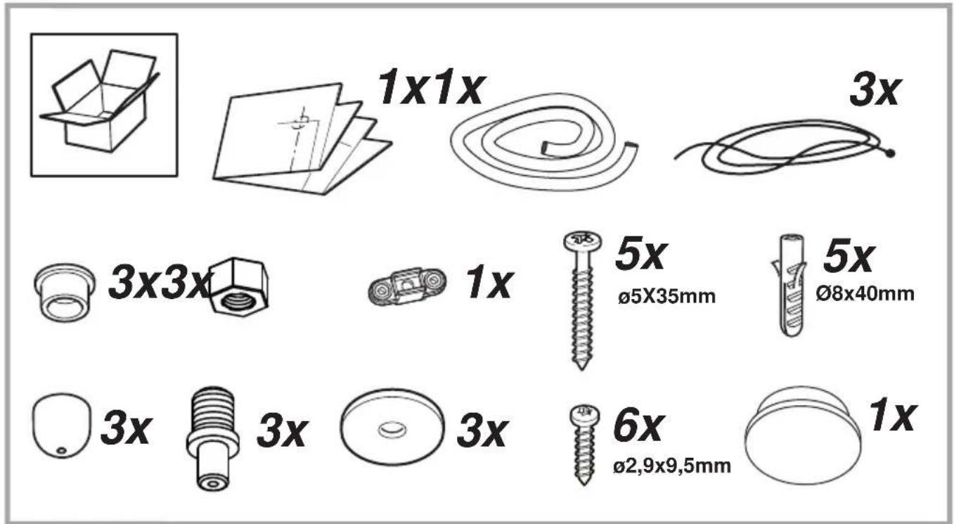
text_image
1x1x 3x 3x3x 1x 5x ø5X35mm 5x Ø8x40mm 3x 3x 3x 6x Ø2,9x9,5mm 1x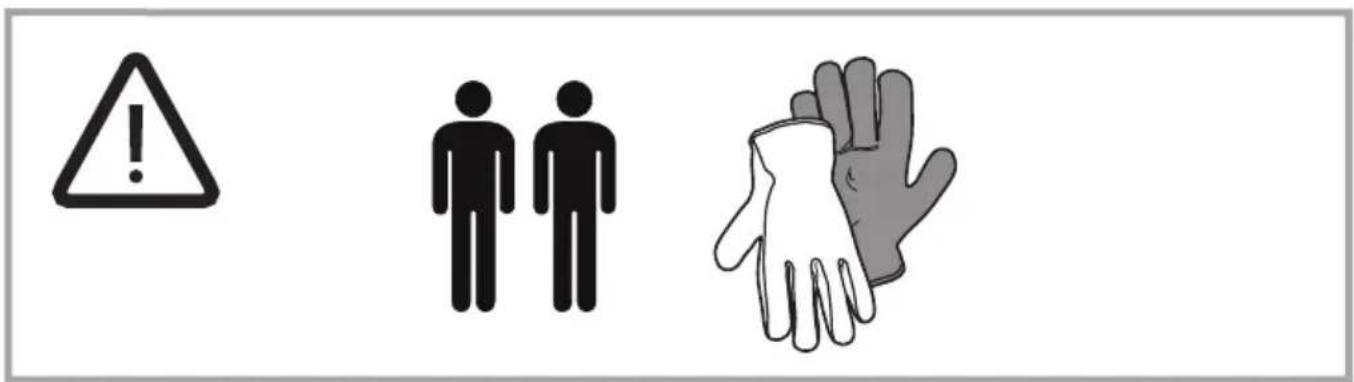
text_image
Warning symbol set with exclamation mark, gender symbols, and hand gesture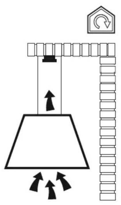
text_image
Diagram illustrating a lifting mechanism with pulley, hanging weights, and directional arrows indicating motion or force.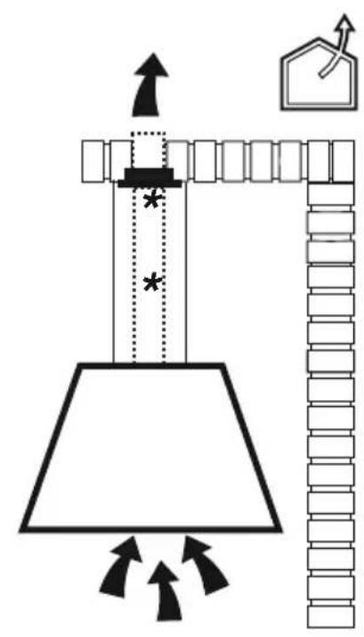
natural_image
Diagram of a mechanical device with arrows indicating motion, no text or symbols present
text_image
Diagram illustrating a roof structure with directional arrows and a house icon, likely for architectural or engineering purposes.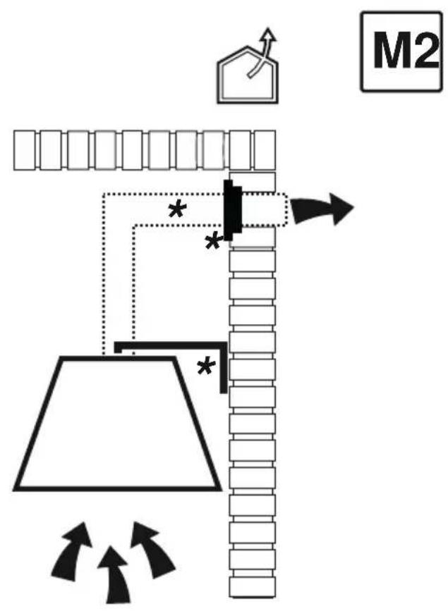
flowchart
graph TD
    A["Start"] --> B["Funnel"]
    B --> C{Decision}
    C -->|Yes| D["House Icon"]
    C -->|No| E["Arrow Right"]
    D --> F["End"]
    E --> G["Arrow Left"]
    G --> H["Downward Arrow"]
    H --> I["Arrow Up"]
    I --> J["Next Step"]
    style A fill:#f9f,stroke:#333
    style J fill:#bbf,stroke:#333
text_image
M2 L1 H1 min. 50cm L1 H1 min. 65cm L1 H1 min. 50cm L1 H1natural_image
Technical line drawing of a mechanical component with mounting holes and internal components (no text or symbols)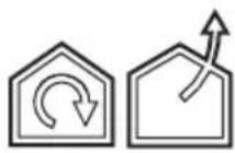
M1
text_image
1x1
text_image
Diagram illustrating a 3D grid-based assembly with a magnified view of a solar panel being inserted into a wire tape.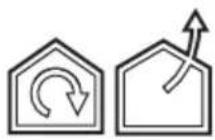
M1
text_image
FRONT2
M1
3x Ø8x40mm
text_image
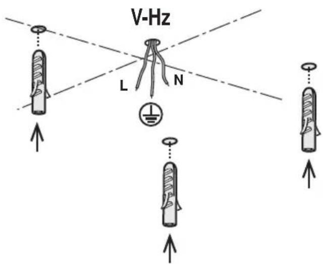
V-Hz L N3
natural_image
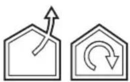
Two simple line diagrams showing a house with an upward arrow and a circular arrow inside, no text or symbols present.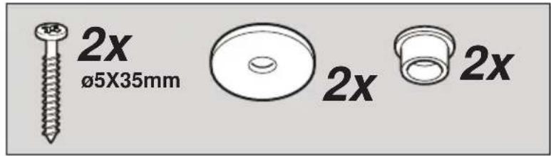
text_image
2x ø5X35mm 2x 2x
a
text_image
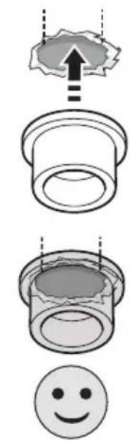
Diagram illustrating three stages of a mechanical or industrial process: top view with an arrow indicating direction, middle view showing a cylindrical component, and bottom view with a smiley face.b
text_image
Diagram illustrating four stages of a hairpin or captoping process with visual cues and facial expressions, including an upward arrow and sad face.4
text_image
V-Hz L N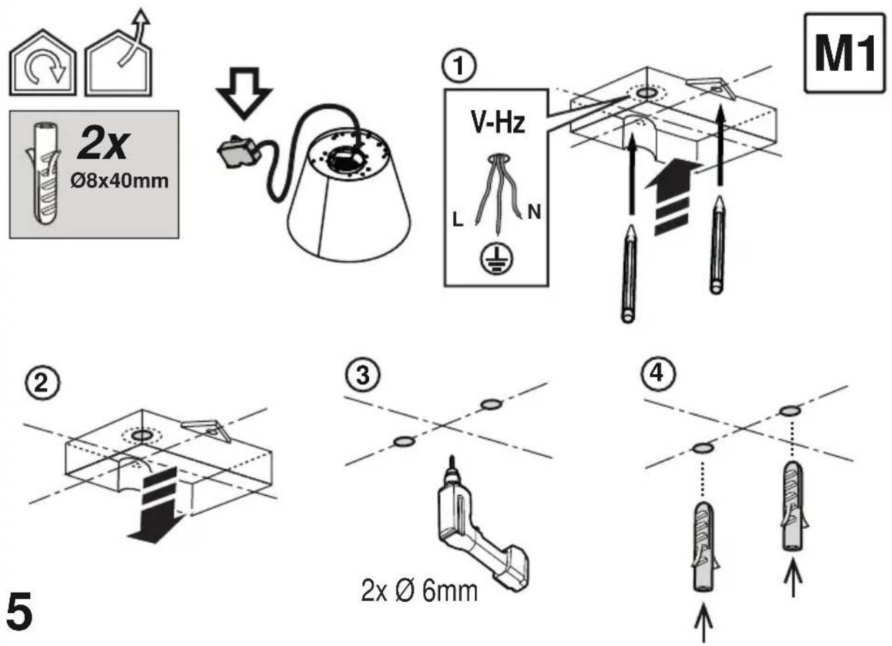
text_image
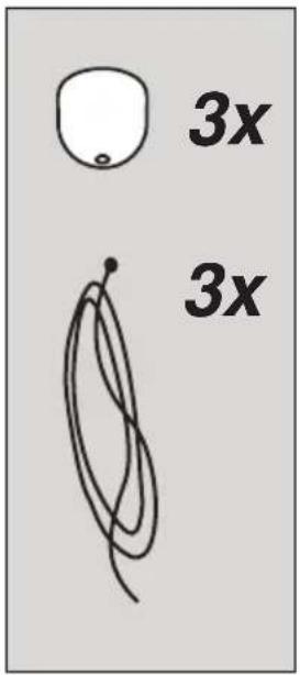
3x 3x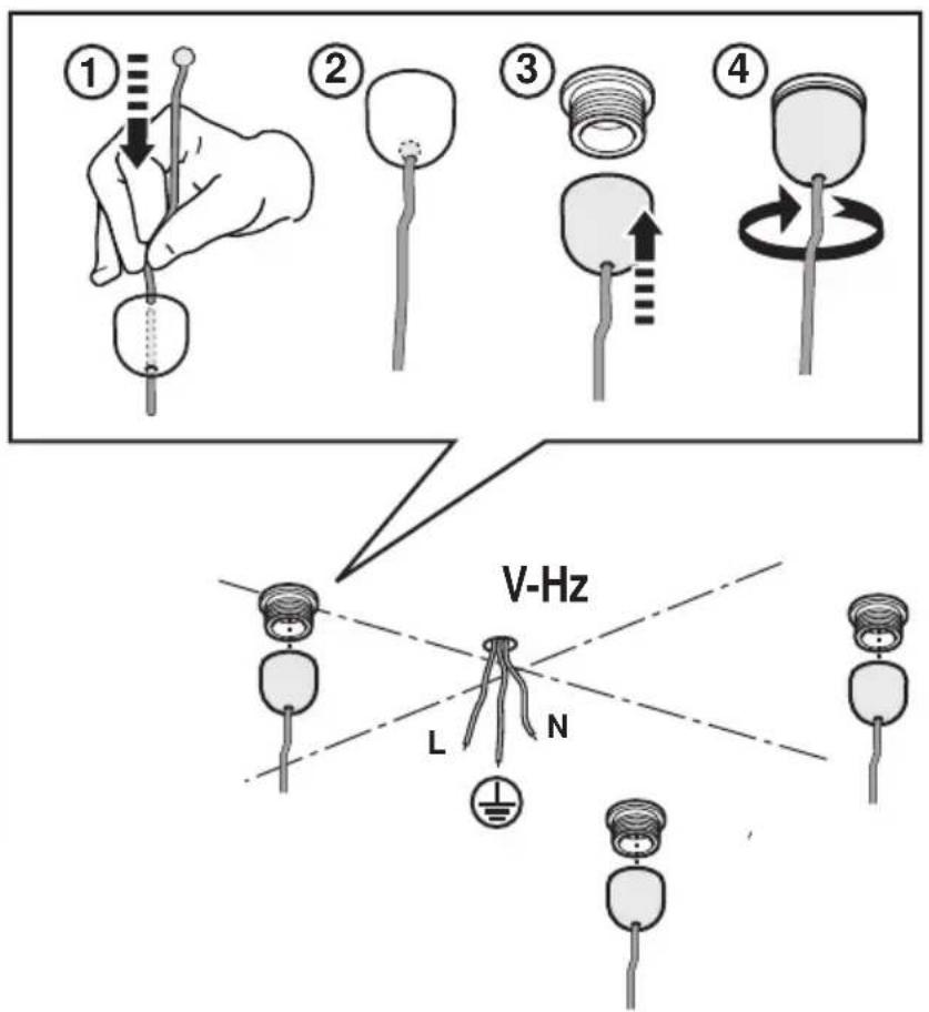
text_image
① ② ③ ④ V-Hz L N
6
7
text_image
Diagram illustrating a mechanical assembly process with labeled steps ① and ②, showing tool application and assembly steps.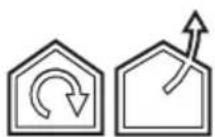
natural_image
Technical illustration of a mechanical assembly with a central component and mounting base (no text or symbols)
natural_image
Simple line drawing of a mechanical setup with an exclamation mark and downward arrow, no text or symbols present.8
text_image
1x
natural_image
Technical line drawing of a mechanical assembly with circular components and directional arrows (no text or symbols)9
text_image
3x M1 10
text_image
3x 3x
text_image
Technical diagram of a mechanical assembly with labeled components and directional arrows indicating assembly steps.
11
natural_image
Diagram of a conical lamp with a slide and cable, showing a downward arrow and internal components (no text or symbols)
natural_image
Technical diagram of a conical component with internal structure and two close-up views showing detail (no text or symbols)12
text_image
13
text_image
Diagram illustrating three steps of a medical procedure: opening lock, adjusting switch, and adjusting catheter with checkmark and cross symbols.
natural_image
Pure diagram showing three basic symbols: a house with rotation arrow, a house with upward arrow, and a gray floor level indicator (no text or labels)
text_image
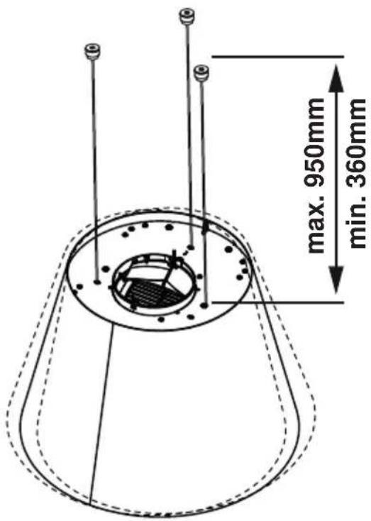
max. 950mm min. 360mm14
text_image
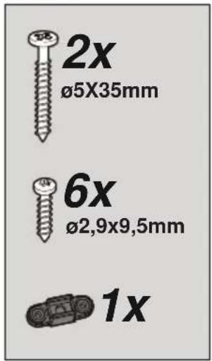
2x Ø5X35mm 6x Ø2.9x9.5mm 1x

V-Hz
natural_image
Diagram of a device connected to a conical lampshade with a cable, showing internal components and wiring (no text or symbols)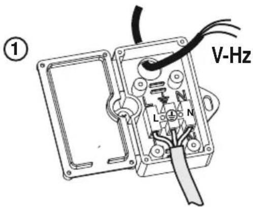
text_image
V-Hz ①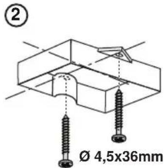
text_image
② Ø 4,5x36mm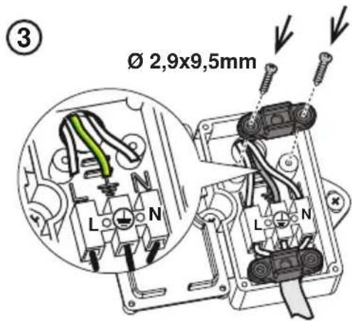
text_image
Ø 2,9x9,5mm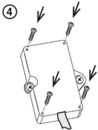
text_image
Diagram of a mechanical device with four screws and directional arrows indicating movement or force, labeled with number 4.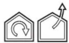
M1
text_image
1x
text_image
Diagram illustrating two steps of a mechanical device with labeled instructions (① and ②) showing how to move or change the component.
natural_image
Line drawing of a conical lamp with a black cable and three vertical posts (no text or symbols)
text_image
M2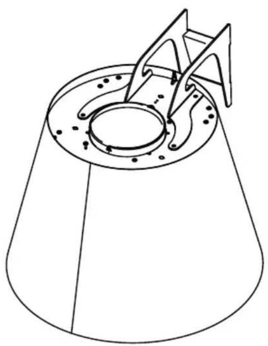
natural_image
Technical line drawing of a conical mechanical component with internal components and mounting holes (no text or symbols)
natural_image
Technical line drawing of a device housing with mounting holes and a central square component (no text or symbols)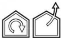
text_image
P1 V-Hz P2 V-Hz
text_image
P1 V-Hz ≤100cm H1 17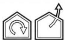
text_image
* 1x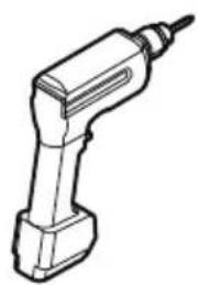
natural_image
Line drawing of a drill bit with a pointed tip (no text or symbols)
text_image
V-Hz m18
4x ∅ 8mm
M2
P1
text_image
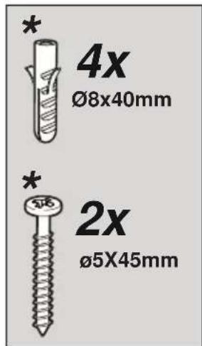
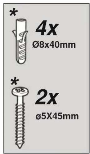
* 4x Ø8x40mm * 2x Ø5X45mm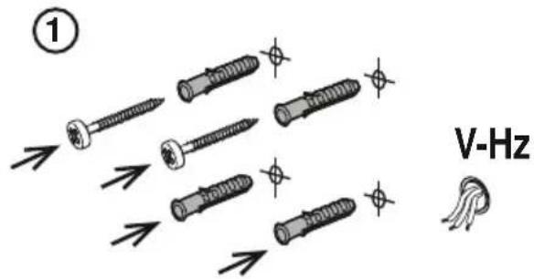
text_image
① V-Hz
text_image
② V-Hz 10mm19
M2
P1
text_image
* 1x
natural_image
Mechanical assembly diagram showing a bracket with bolts and a directional arrow, no text or symbols presentM2
text_image
Technical diagram of a mechanical bracket assembly with labeled parts and directional arrow
text_image
Diagram showing three symbols: a padlock with plus sign, a circle with plus sign and downward arrow, and a checkmark.
text_image
③
text_image
2x ø5X45mm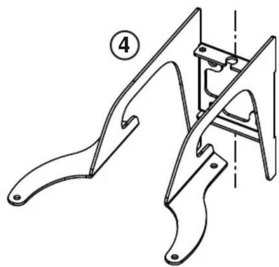
natural_image
Technical line drawing of a mechanical bracket assembly (no text or symbols)
natural_image
Pure electrical circuit lines without any symbols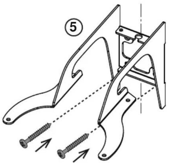
text_image
⑤20.1
text_image
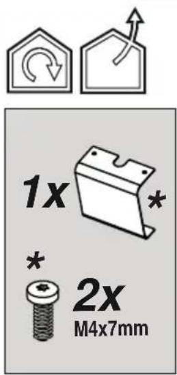
1x 2x M4x7mm20.2
text_image
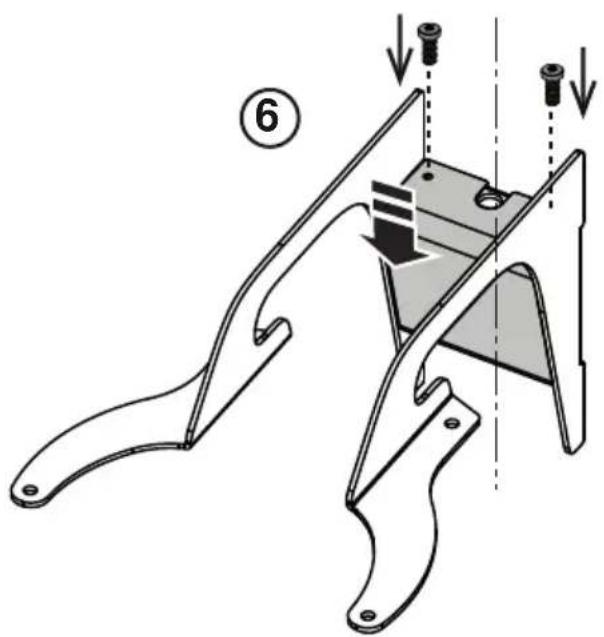
Technical diagram of a mechanical component with labeled parts and directional arrows indicating assembly or assembly steps.
21
text_image
7-8-9 12

natural_image
Simple line drawing of an open book with a page number 22 on the right (no text or symbols on the pages)
text_image
* 4x M6 x 16 mm
M2
text_image
Diagram illustrating a mechanical assembly with labeled parts and directional arrows, showing components like bolts and a conical base.22
text_image
2x Ø6x30mm
text_image
V-Hz ①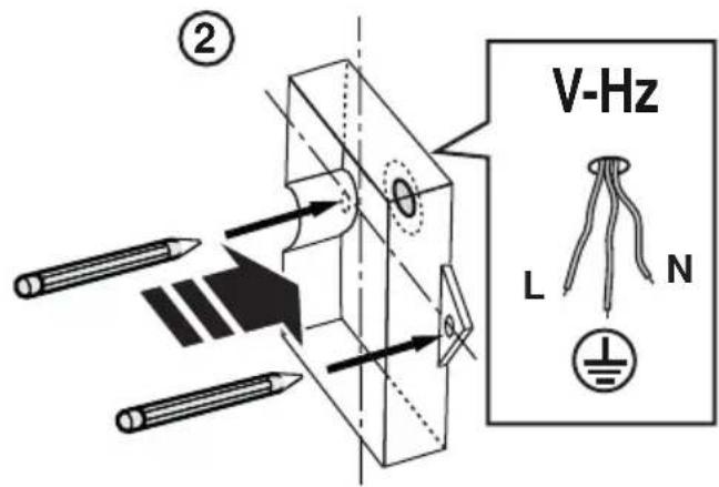
text_image
V-Hz L N ②
text_image
③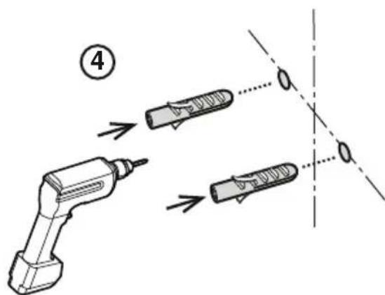
text_image
Diagram showing a tool interacting with three labeled parts, illustrating a process or assembly step.2x ∅ 6mm
23
24

text_image
15 25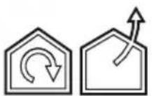
text_image
1x
text_image
Diagram illustrating a mechanical assembly process with labeled steps ① and ② showing motion of a component.
natural_image
Line drawing of a conical lamp with a base and spout, no text or symbols present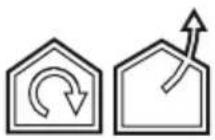
text_image
P1 V-Hz P2 V-Hz
text_image
P2 V-Hz H1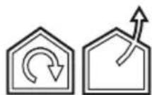
text_image
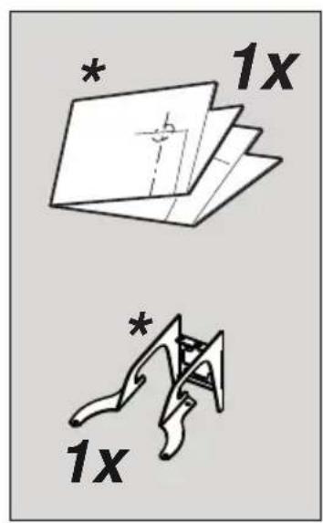
* 1x * 1x
text_image
V-Hz
text_image
V-Hz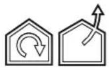

natural_image
Technical line drawing of a mechanical assembly with no visible text or symbols

text_image
V-Hz
text_image
V-Hz
natural_image
Diagram of a mechanical assembly with an arrow indicating direction, no text or symbols present
natural_image
Pure mechanical assembly diagram without any text, numbers, or symbols28

natural_image
Line drawing of a drill bit with a pointed tip (no text or symbols)4x ∅ 8mm
text_image
V-HzM2
P2
29
text_image
* 4x Ø8x40mm * 2x Ø5X45mm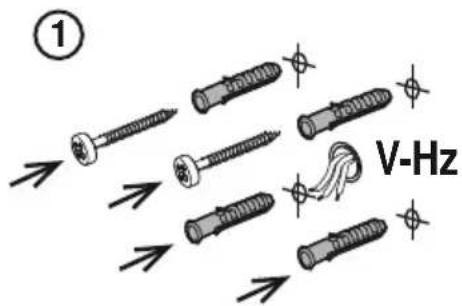
text_image
① V-Hz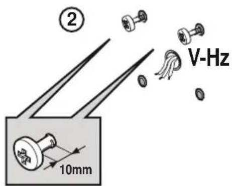
text_image
② V-Hz 10mmM2
P2
30
31
text_image
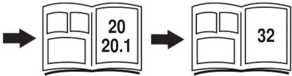
20 20.1 32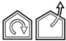
text_image
* 1x
text_image
Technical diagram illustrating a mechanical assembly with labeled components and directional arrows indicating motion or force.
natural_image
Mechanical assembly diagram showing a lever mechanism with a curved tool inserted into a housing (no text or symbols present)
natural_image
Mechanical assembly diagram showing a bracket with mounting holes and a rotating component (no text or labels)32

text_image
1x * 2x M4x7mm32.1
text_image
Technical diagram of a mechanical device with numbered components and directional arrows indicating assembly steps.
flowchart
graph LR
    A["32.2"] --> B["22"]
    B --> C["33"]
natural_image
Diagram of a device component with a black arrow pointing upward, no text or symbols present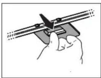
natural_image
Illustration of a hand using a tool to adjust or install a mechanical component (no text or symbols visible)33
text_image
Technical diagram illustrating the assembly of a solar panel with labeled components and directional arrows indicating process flow.34
text_image
Diagram showing a device inside a dome-shaped container with directional arrows and icons for home, battery, and wrench functions.35
text_image
Diagram showing a house icon with an upward arrow and a circular object labeled ①, positioned on a 3D coordinate axis.
text_image
② 1 x Ø2,9x5mm
text_image
③
text_image
④ x3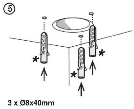
text_image
⑤ 3 x Ø8x40mm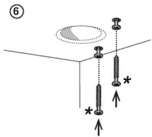
text_image
(6)
text_image
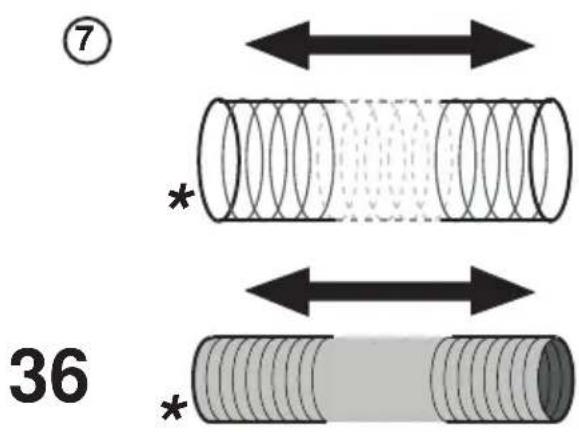
⑦ * 36 *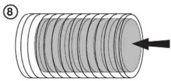
natural_image
Diagram of a cylindrical object with concentric grooves and an arrow pointing to it, no text or symbols present.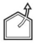
⑨
text_image
Diagram illustrating a mechanical assembly process with a ring component and a threaded component, showing a downward arrow indicating motion.10
text_image
1 x Ø125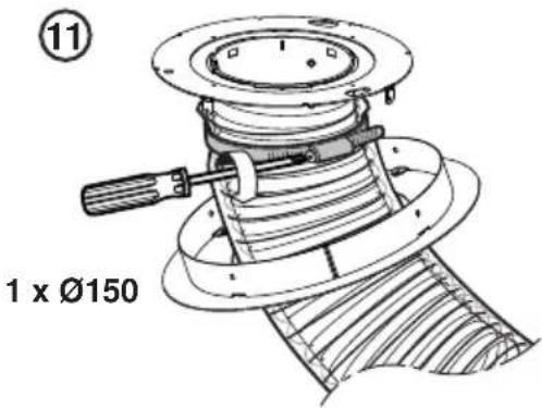
text_image
⑪ 1 x Ø150
natural_image
Technical diagram of a mechanical component with arrows indicating motion or assembly (no text or symbols)⑬ 14
natural_image
Technical line drawing of a cylindrical mechanical component with two tools, no text or symbols presentO
natural_image
Technical line drawing of a cylindrical mechanical component with screw fasteners and mounting holes (no text or symbols)36.1
14
natural_image
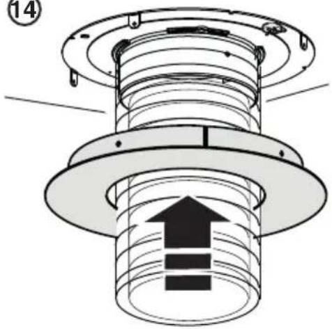
Technical diagram of a mechanical assembly with concentric rings and a central upward arrow (no text or symbols)15
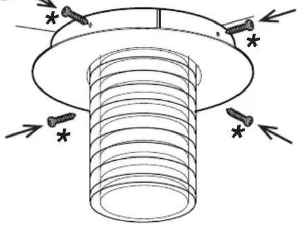
4 x ∅3,5x6,5mm
natural_image
Technical line drawing of a mechanical component with screw fasteners and mounting holes (no text or symbols)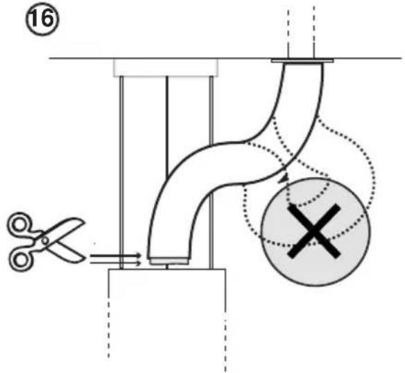
text_image
(16)
text_image
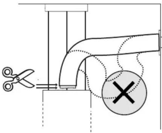
Diagram illustrating a pipe connection with scissors, a cross symbol, and a warning sign, likely for safety or repair instructions.17
text_image
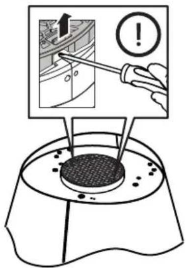
Diagram illustrating a mechanical testing setup with a tool, warning symbol, and magnified view of the component.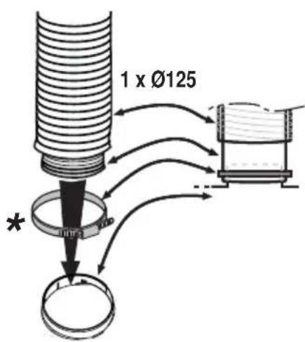
text_image
1 x Ø125 *
natural_image
Diagram of a mechanical component with threaded shaft and base, showing internal threading and mounting features (no text or symbols)36.2
EN - Instruction on mounting and use
Closely follow the instructions set out in this manual. All responsibility, for any eventual inconveniences, damages or fires caused by not complying with the instructions in this manual, is declined. This appliance is intended to be used in household and similar application such as: - staff kitchen areas in shop, offices and other working environments; - farm houses; - by clients in hotels, motels and other residential type environments; - bed and breakfast type environments.
The hood can look different to that illustrated in the drawings in this booklet. The instructions for use, maintenance and installation, however, remain the same.
- It is important to conserve this booklet for consultation at any moment. In the case of sale, cession or move, make sure it is together with the product.
- Read the instructions carefully: there is important information about installation, use and safety.
- Do not carry out electrical or mechanical variations on the product or on the discharge conduits.
- Before proceeding with the installation of the appliance verify that there are no damaged all components. Otherwise contact your dealer and do not proceed with the installation.
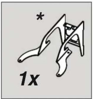
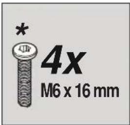
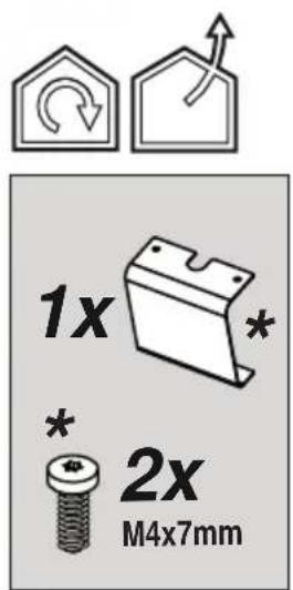
Note: The parts marked with the symbol "(*)" are optional accessories supplied only with some models or otherwise not supplied, but available for purchase.
Caution
- Before any cleaning or maintenance operation, disconnect hood from the mains by removing the plug or disconnecting the mains electrical supply.
• Always wear work gloves for all installation and maintenance operations. - This appliance can be used by children aged from 8 years and above and persons with reduced physical, sensory or mental capabilities or lack of experience and knowledge if they have been given supervision or instruction concerning use of the appliance in a safe way and understand the hazards involved.
• Children shall not be allowed to tamper with the controls or play with the appliance. - Cleaning and user maintenance shall not be made by children without supervision.
- The premises where the appliance is installed must be sufficiently ventilated, when the kitchen hood is used together with other gas combustion devices or other
fuels.
- The hood must be regularly cleaned on both the inside and outside (AT LEAST ONCE A MONTH).
- This must be completed in accordance with the maintenance instructions provided. Failure to follow the instructions provided regarding the cleaning of the hood and filters will lead to the risk of fires.
- Do not flambé under the range hood.
- Do not remove filters during cooking.
- For lamp replacement use only lamp type indicated in the Maintenance/Replacing lamps section of this manual.
The use of exposed flames is detrimental to the filters and may cause a fire risk, and must therefore be avoided in all circumstances.
Any frying must be done with care in order to make sure that the oil does not overheat and ignite.
CAUTION: Accessible parts of the hood may become hot when used with cooking appliances.
- Do not connect the appliance to the mains until the installation is fully complete.
- With regards to the technical and safety measures to be adopted for fume discharging it is important to closely follow the regulations provided by the local authorities.
- The air must not be discharged into a flue that is used for exhausting fumes from appliance burning gas or other fuels.
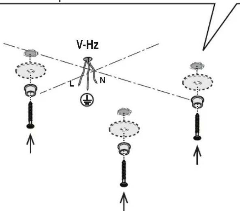
⚠ WARNING! Failure to install the screws or fixing device in accordance with these instructions may result in electrical hazards.
- Do not use or leave the hood without the lamp correctly mounted due to the possible risk of electric shocks.
- Never use the hood without effectively mounted grids.
- The hood must NEVER be used as a support surface unless specifically indicated.
- Use only the fixing screws supplied with the product for installation or, if not supplied, purchase the correct screws type.
- Use the correct length for the screws which are identified in the Installation Guide.
- In case of doubt, consult an authorized service assistance center or similar qualified person.
⚠ WARNING! Do not use with a programmer, timer, separate remote control system or any other device that switches on automatically.
Electrical connection
The mains tension must correspond to the tension shown on the characteristic label situated inside the hood.
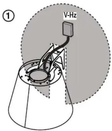
The product is meant for connecting directly to the mains supply, therefore apply a regulation bipolar switch that ensures complete disconnection from the mains in the conditions of category III over-tension, conforming to the installation rules.
Warining! Changing the interconnection cable must be carried out by the authorised technical assistance service.
Installation
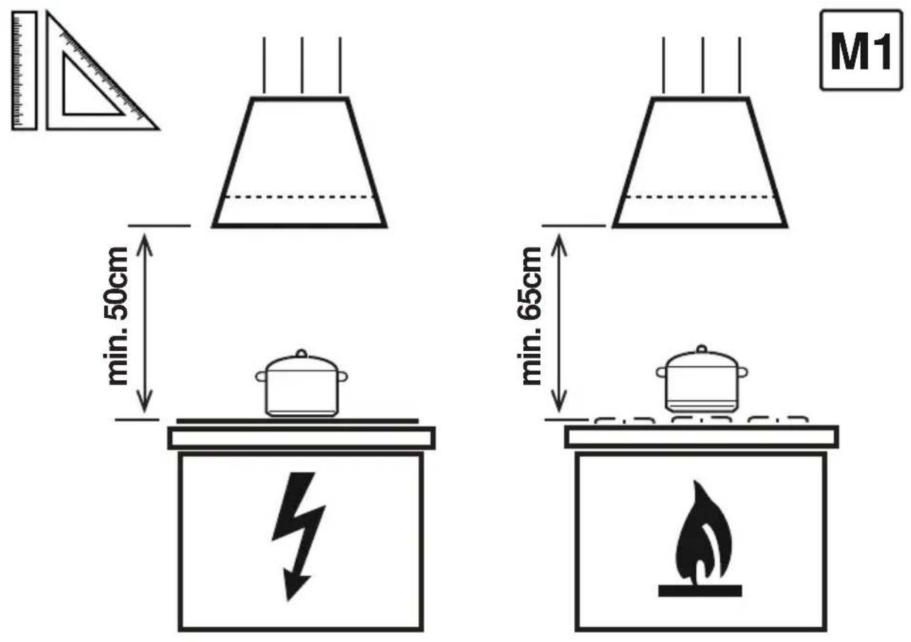
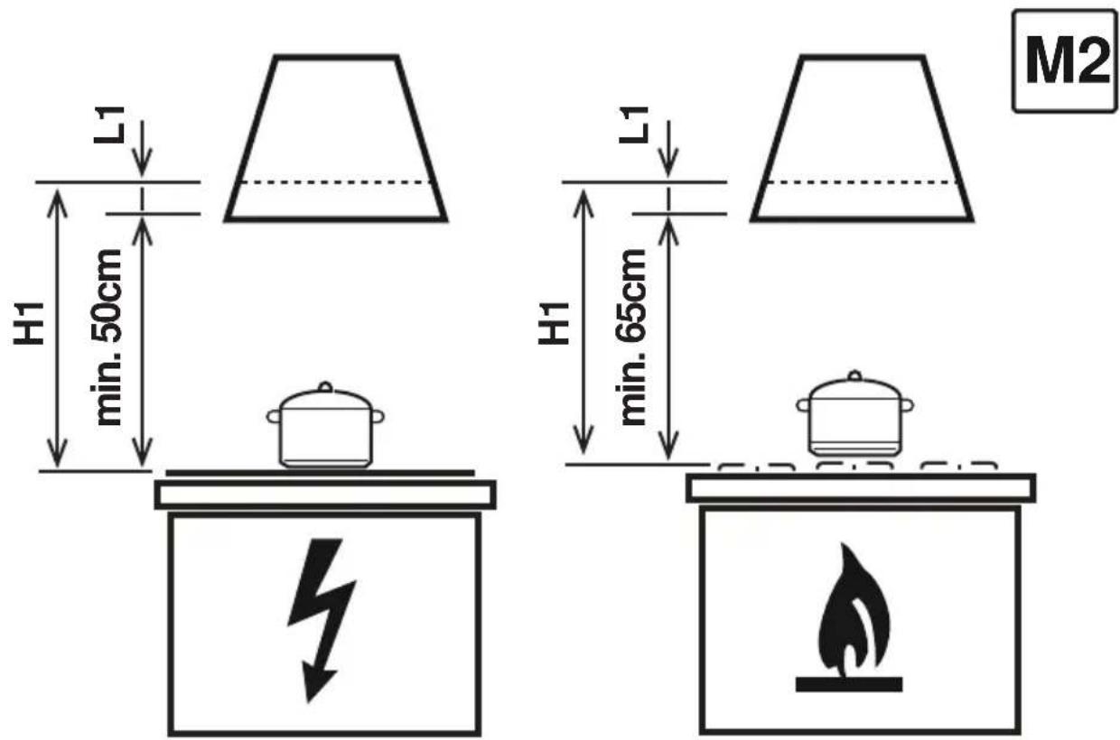
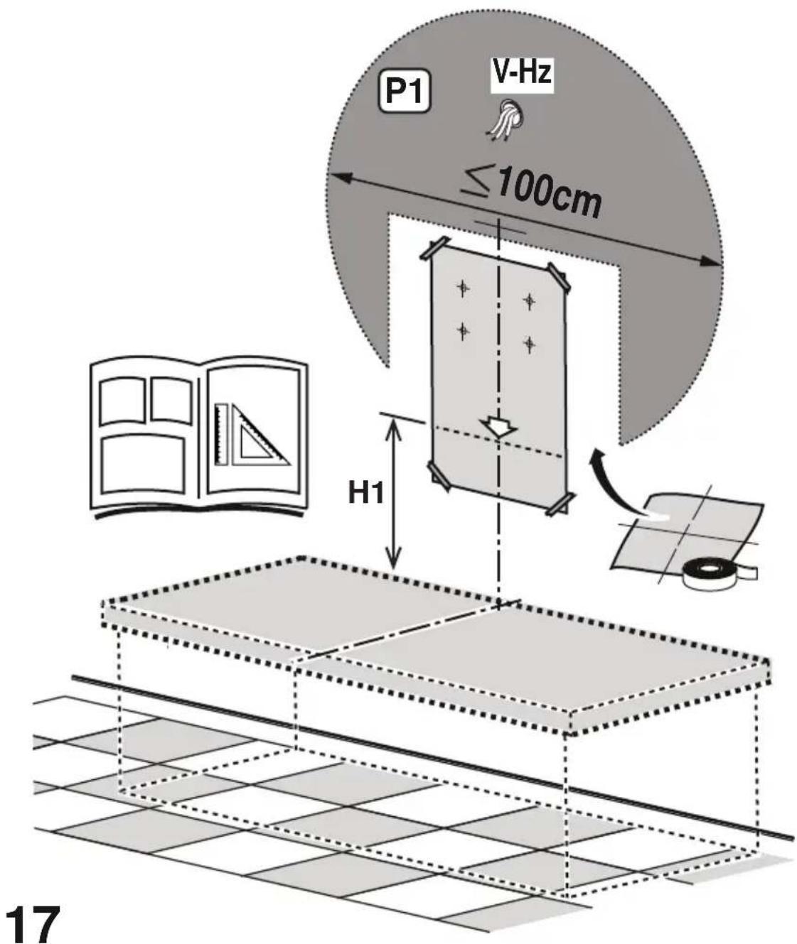
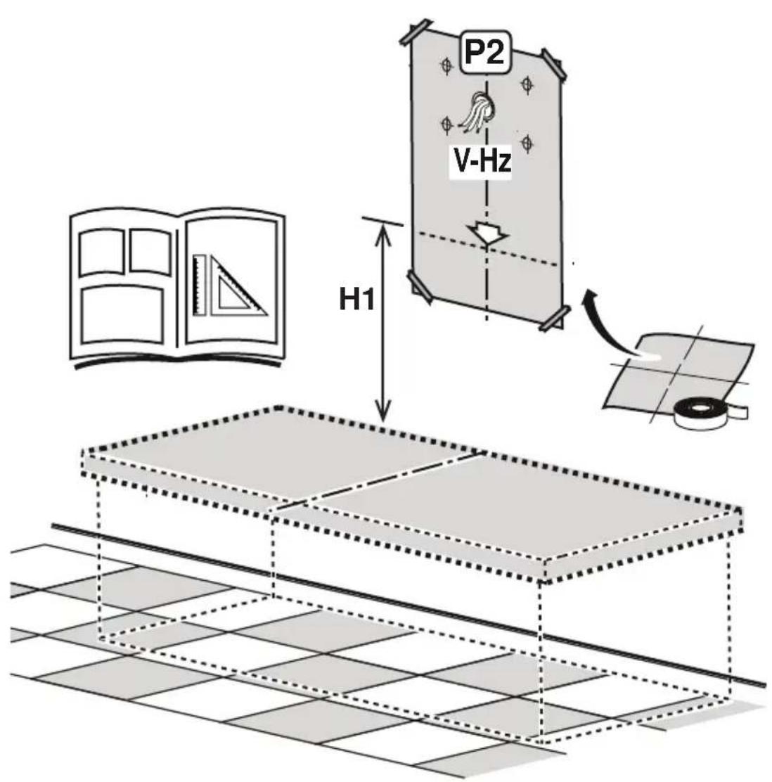
- The minimum distance between the supporting surface for the cooking equipment on the hob and the lowest part of the range hood must be not less than 50cm from electric cookers and 65cm from gas or mixed cookers.
If the instructions for installation for the gas hob specify a greater distance, this must be adhered to.
Specialised personnel must carry out both the electrical and the mechanical installation.
- This appliance is marked according to the European directive 2012/19/EC - UK SI 2013 No.3113 on Waste Electrical and Electronic Equipment (WEEE).
- By ensuring this product is disposed of correctly, you will help prevent potential negative consequences for the environment and human health, which could otherwise be caused by inappropriate waste handling of this product.
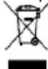
- The symbol ■ on the product, or on the documents accompanying the product, indicates that this appliance may not be treated as household waste. Instead it should be taken to the appropriate collection point for the recycling of electrical and electronic equipment. Disposal must be carried out in accordance with local environmental regulations for waste disposal.
- For further detailed information regarding the process, collection and recycling of this product, please contact the appropriate department of your local authorities or the local department for household waste or the shop where you purchased this product.
Appliance designed, tested and manufactured according to:
• Safety: EN/IEC 60335-1; EN/IEC 60335-2-31, EN/IEC 62233.
• Performance: EN/IEC 61591; ISO 5167-1; ISO 5167-3; ISO 5168; EN/IEC 60704-1; EN/IEC 60704-2-13; EN/IEC 60704-3; ISO 3741; EN 50564; IEC 62301.
- EMC: EN 55014-1; CISPR 14-1; EN 55014-2; CISPR 14-2; EN/IEC 61000-3-2; EN/IEC 61000-3-3. Suggestions for a correct use in order to reduce the environmental impact: Switch ON the hood at minimum speed when you start cooking and kept it running for few minutes after cooking is finished. Increase the speed only in case of large amount of smoke and vapor and use boost speed(s) only in extreme situations. Replace the charcoal filter(s) when necessary to maintain a good odor reduction efficiency. Clean the grease filter(s) when necessary to maintain a good grease filter efficiency. Use the maximum diameter of the ducting system indicated in this manual to optimize efficiency and minimize noise.
Use
The hood is conceived for the suction of cooking fumes and steam and is destined only for domestic use.
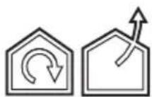
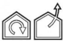
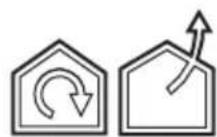
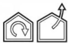
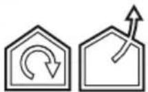
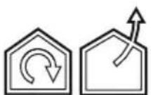
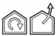
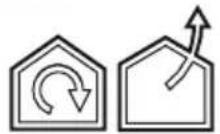
The hood is designed to be used either for exhausting or filter version.

Extraction version
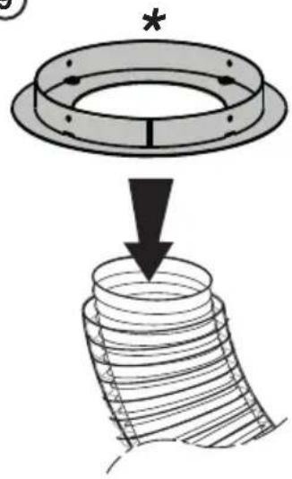
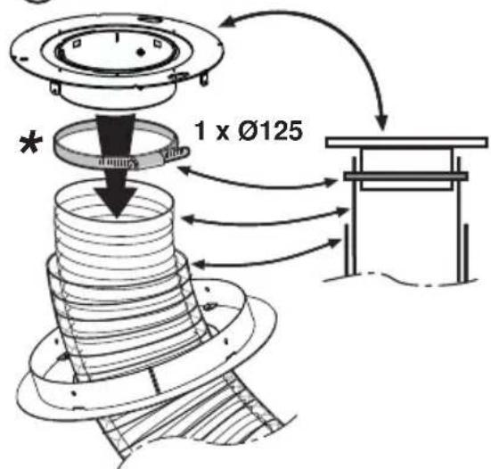
In this case the fumes are conveyed outside of the building by means of a special pipe connected with the connection ring located on top of the hood.

CAUTION!
The exhausting pipe is not supplied and must be purchased apart.
Diameter of the exhausting pipe must be equal to that of the connection ring.

CAUTION!
If the hood is supplied with active charcoal filter, then it must be removed.
Connect the hood and discharge holes on the walls with a diameter equivalent to the air outlet (connection flange).
Using the tubes and discharge holes on walls with smaller dimensions will cause a diminution of the suction performance and a drastic increase in noise.
Any responsibility in the matter is therefore declined.
! Use a duct of the minimum indispensable length.
! Use a duct with as few elbows as possible (maximum elbow angle: 90°).
! Avoid drastic changes in the duct cross-section.

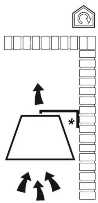
Filtration version
The aspirated air will be degreased and deodorised before being fed back into the room.
In order to use the hood in this version, you have to install a system of additional filtering based on activated charcoal.
Mounting
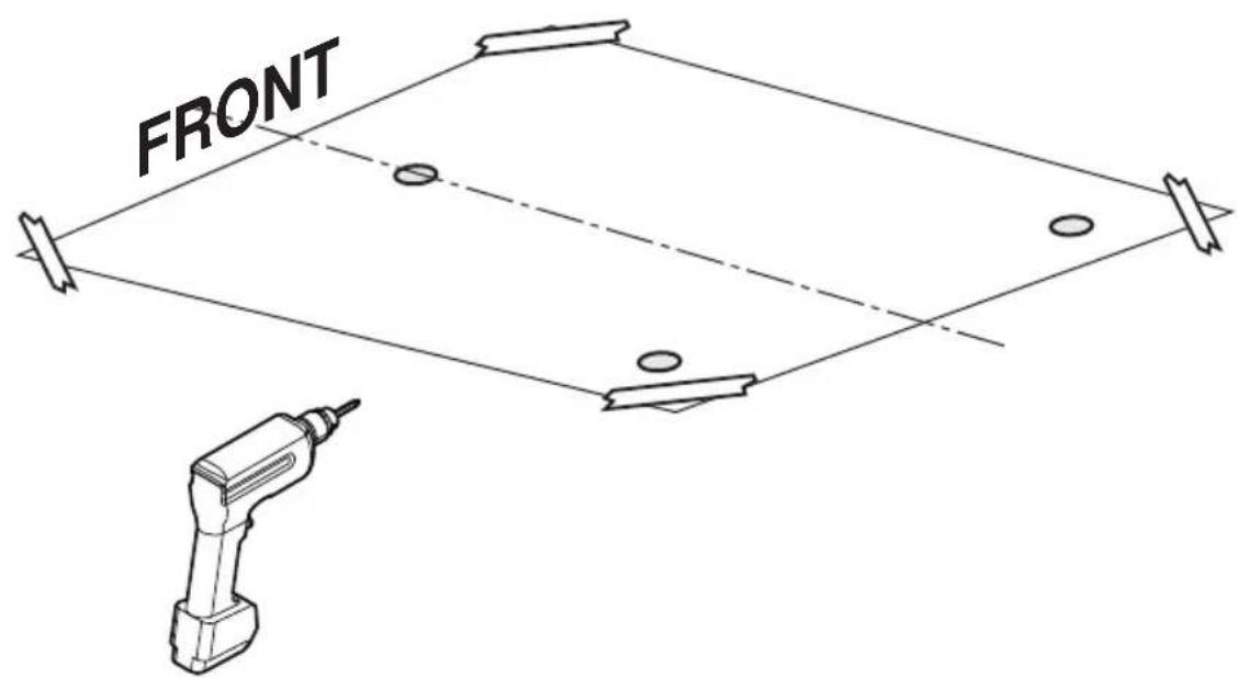
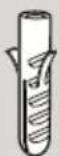
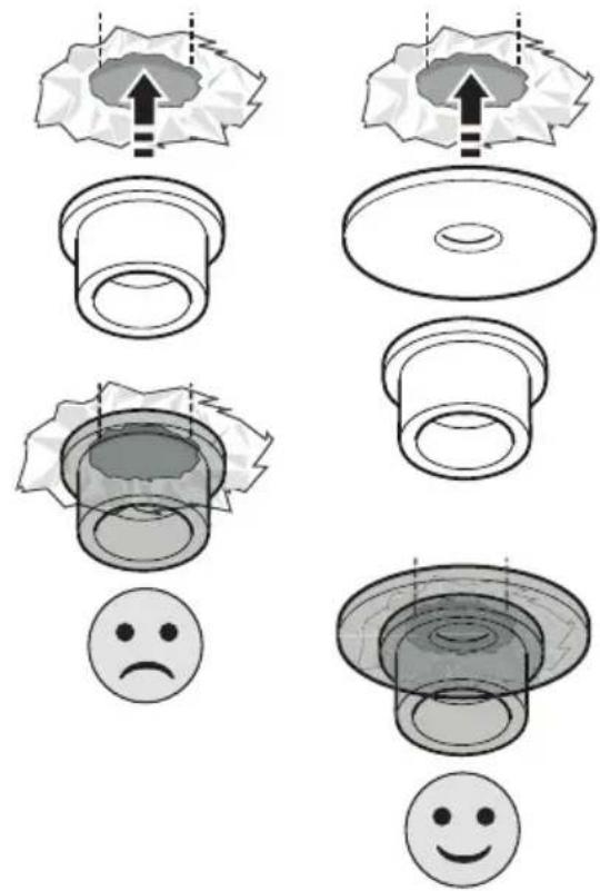
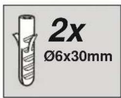
Expansion wall plugs are provided to secure the hood to most types of walls/ceilings. However, a qualified technician must verify suitability of the materials in accordance with the type of wall/ceiling. The wall/ceiling must be strong enough to take the weight of the hood.
Do not tile, grout or silicone this appliance to the wall. Surface mounting only.
Operation
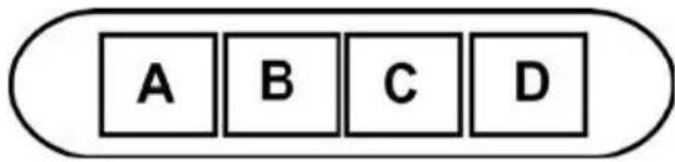
The hood is fitted with a control panel with aspiration speed selection control and a light switch to control cooking area lights.
text_image
A B C DA. on/off light switch
B. on/off aspiration switch and minimum power selection
B+C. medium power selection aspiration switch
B+D. maximum power selection aspiration switch
Maintenance
Cleaning
Clean using ONLY a cloth dampened with neutral liquid detergent. DO NOT CLEAN WITH TOOLS OR
INSTRUMENTS. Do not use abrasive products. DO NOT USE ALCOHOL!
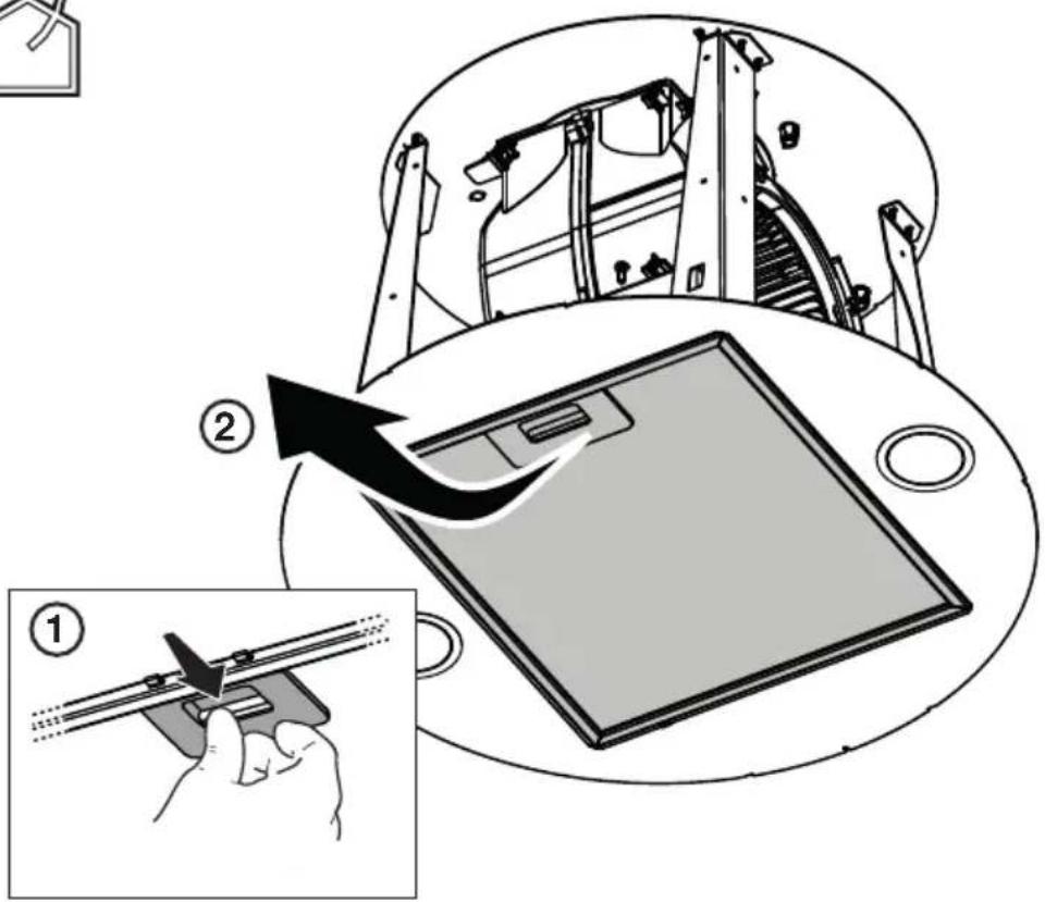
Grease filter
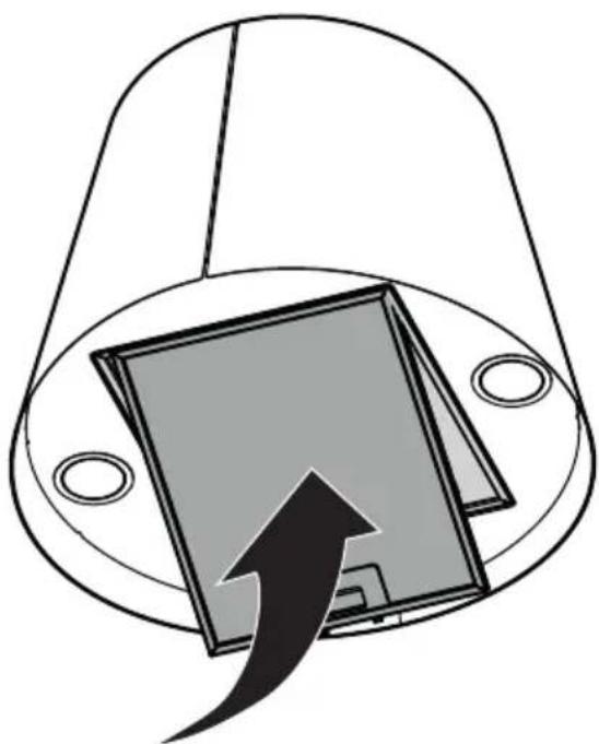
Fig. 35
Traps cooking grease particles.
The grease filter must be cleaned once a month using non aggressive detergents, either by hand or in the dishwasher, which must be set to a low temperature and a short cycle.
When washed in a dishwasher, the grease filter may discolor slightly, but this does not affect its filtering capacity.
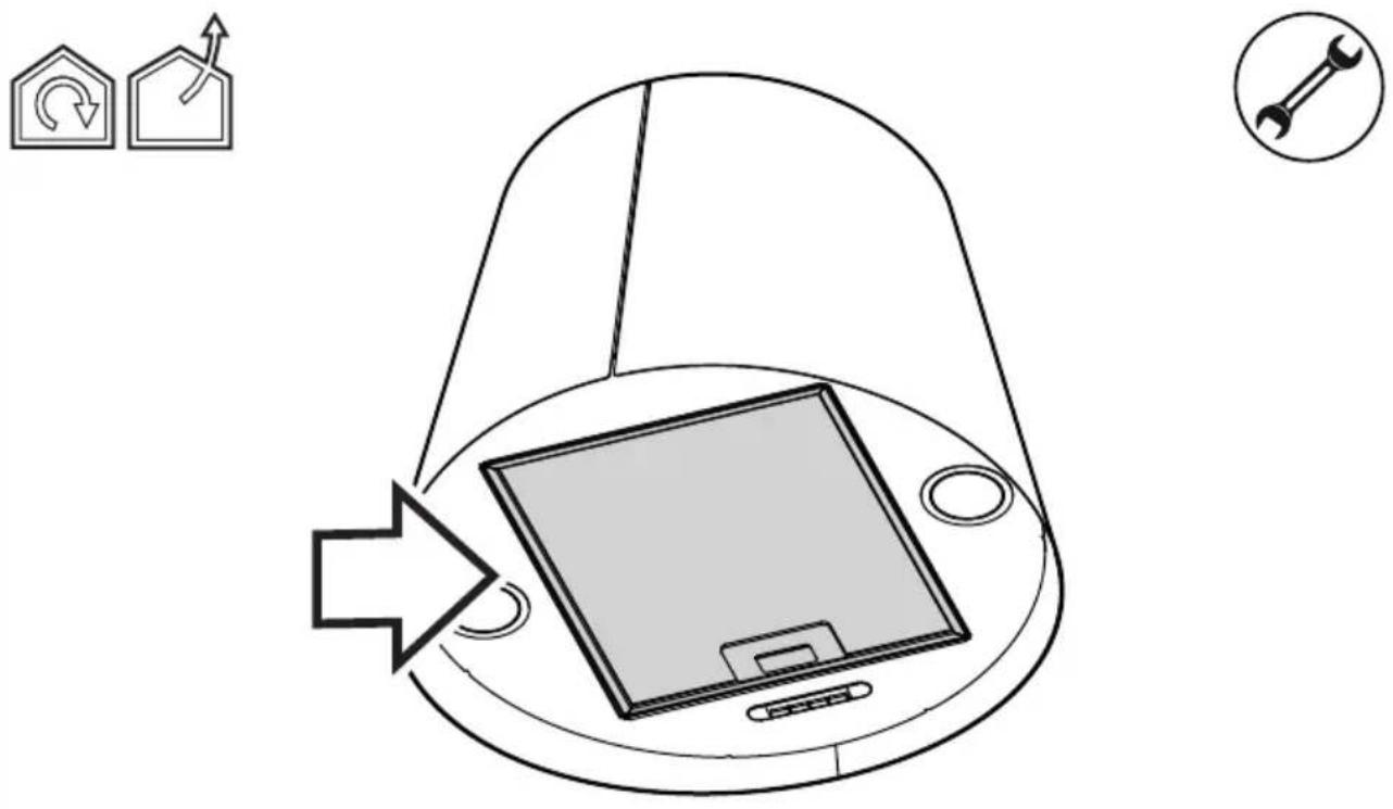
Charcoal filter (filter version only)
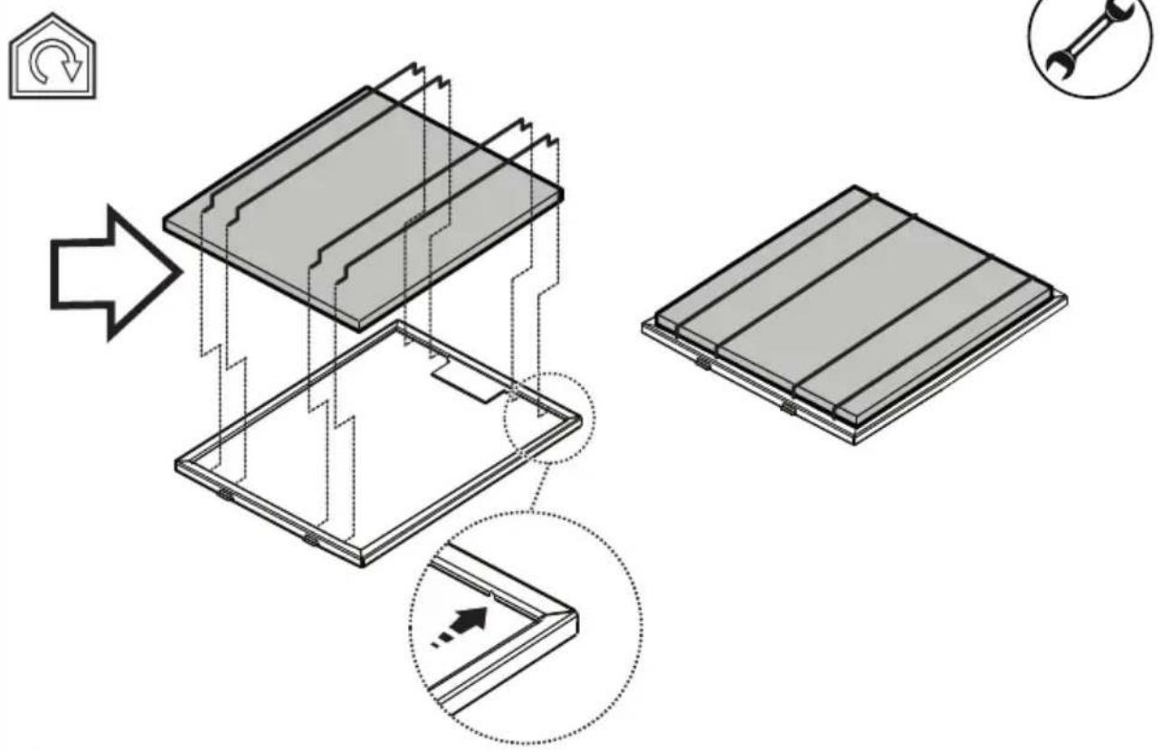
Fig. 34
It absorbs unpleasant odors caused by cooking.
The charcoal filter can be washed once every two months using hot water and a suitable detergent, or in a dishwasher at 65^ C (if the dishwasher is used, select the full cycle function and leave dishes out).
Eliminate excess water without damaging the filter, then put it in the oven for 10 minutes at 100^ C to dry completely.
Replace the mattress every 3 years and when the cloth is damaged.
- Montage
Install the carbon filter on the back of the grease filter and fix with 4 rods.
Attention! The rods are included in the carbon filter packing and not on the hood.
• To dismantle the filter act in the reverse manner.
Replacing lamps
The hood is equipped with a lighting system based on LED technology.
The LEDs guarantee an optimum lighting, a duration up to 10 times longer than the traditional lamps and allow to save 90% electrical energy.
For replacement, contact the technical service.
A. Lysbryter ON/OFF.