
Leone ELI142S1 - Air conditioner ELICA - Free user manual and instructions
Find the device manual for free Leone ELI142S1 ELICA in PDF.
| Product Type | Inline fan system for ventilation (air conditioner) |
| Brand | Elica |
| Model | Leone ELI142S1 |
| Category | Air conditioner / Inline fan |
| Power supply | 120 V, 60 Hz, 15 A (dedicated circuit) |
| Weight | 22.6 kg (50 lb) |
| Cabinet dimensions (approx.) | 30 x 30 x 30 cm |
| Recommended duct diameter | 8" (20.32 cm) to 10" (25.4 cm) round metal |
| Duct type | Rigid metal only (no plastic or aluminum) |
| Hood compatibility | Specific Elica models (ECL, EVV, ELN, etc.) |
| Number of speeds | Multi-speed (6 or 9 wire wiring) |
| Cabinet material | Steel |
| Installation | Ceiling, wall or roof; with exhaust duct to the outside |
| Safety | Cut power before maintenance; use grounding conductors; do not use with speed control |
| Maintenance | Clean grease filters and impellers regularly |
| Warranty | 2 years parts and labor (domestic use) |
| Intended use | General kitchen ventilation, grease and odor extraction |
| Certifications | UL, CSA (electrical compliance) |
| Included accessories | Brackets, screws, connectors, strain relief |
| Operating temperature | Indoor use, temperate climates |
Frequently Asked Questions - Leone ELI142S1 ELICA
User questions about Leone ELI142S1 ELICA
0 question about this device. Answer the ones you know or ask your own.
Ask a new question about this device
Download the instructions for your Air conditioner in PDF format for free! Find your manual Leone ELI142S1 - ELICA and take your electronic device back in hand. On this page are published all the documents necessary for the use of your device. Leone ELI142S1 by ELICA.
USER MANUAL Leone ELI142S1 ELICA
Use, Care, and Installation Guide
READ AND SAVE THESE INSTRUCTIONS
LISEZ CES INSTRUCTIONS ET CONSERVEZ-LES
LEAY CONSERVE ESTAS INSTRUCCIONES
Models: KIT0154387
LIB0152213 Printed in Mexico 10/18
ENGLISH
Contents
Important safety notice. 3
Installation Requirements 4
Tools & Parts 4
Location Requirements 5
Product Dimension 5
Venting Requirements 5
Electrical Requirements 6
Installation Instructions 6
Prepare the location 6
Install In-Blower System 9
Make electrical connection for the In-Line Blower System. 10
Make electrical between the In-Line Blower System and Range Hood 11
Warranty 14
43
APPROVED FOR RESIDENTIAL APPLIANCES
READ AND SAVE THESE INSTRUCTIONS
PLEASE READ ENTIRE INSTRUCTIONS BEFORE PROCEEDING.
INSTALLATION MUST COMPLY WITH ALL LOCAL CODES.
IMPORTANT: Save these Instructions for the Local Electrical Inspector's use.
INSTALLER: Please leave these Instructions with this unit for the owner.
OWNER: Please retain these instructions for future reference.
Safety Warning: Turn off power circuit at service panel and lock out panel, before wiring this appliance.
Requirement: 120 V AC, 60 Hz. 15 or 20 A Branch Circuit.

IMPORTANT SAFETY NOTICE
CAUTION
FOR GENERAL VENTILATING USE ONLY. DO NOT USE TO EXHAUST HAZARDOUS OR EXPLOSIVE MATERIALS OR VAPOURS.
WARNING
TO REDUCE THE RISK OF FIRE, ELECTRIC SHOCK, OR INJURY TO PERSONS, OBSERVE THE FOLLOWING:
A. Use this unit only in the manner intended by the manufacturer. If you have questions, contact the manufacturer.
B. Before servicing or cleaning the unit, switch power off at service panel and lock service panel disconnecting means to prevent power from being switched on accidentally.
When the service disconnecting means cannot be locked, securely fasten a prominent warning device, such as a tag, to the service panel.
C. Installation work and electrical wiring must be done by qualified person(s) in accordance with all applicable codes & standards, including fire-rated construction.
D. Sufficient air is needed for proper combustion and exhausting of gases through the flue (Chimney) of fuel burning equipment to prevent back- drafting. Follow the heating equipment manufacturers guideline and safety standards such as those published by the national fire protection association (NFPA), the american society for heating, refrigeration and air conditioning engineers (ASHRAE), and the local code authorities.
E. When cutting or drilling into wall or ceiling, do not damage electrical wiring and other hidden utilities.
F. Ducted fans must always be vented to the outdoors.
CAUTION
To reduce risk of fire and to properly exhaust air, be sure to duct air outside - do not vent exhaust air into spaces within walls, ceilings, attics, crawl spaces, or garages.
WARNING
TO REDUCE THE RISK OF FIRE, USE ONLY METAL DUCT WORK.
Install this accessory in accordance with all requirements specified.
WARNING
To reduce the risk of fire or electric shock, do not use this hood with any external solid state speed control device.
WARNING
TO REDUCE THE RISK OF A RANGE TOP GREASE FIRE.
a) Never leave surface units unattended at high settings. Boilovers cause smoking and greasy spillovers that may ignite. Heat oils slowly on low or medium settings.
b) Always turn hood ON when cooking at high heat or when flambeing food (i.e. Crepes Suzette, Cherries Jubilee, Peppercorn Beef Flambe').
c) Clean ventilating fans frequently. Grease should not be allowed to accumulate on fan or filter.
d) Use proper pan size. Always use cookware appropriate for the size of the surface element.
WARNING
TO REDUCE THE RISK OF INJURY TO PERSONS, IN THE EVENT OF A RANGE TOP GREASE FIRE, OBSERVE THE FOLLOWING:3
a) SMOTHER FLAMES with a close-fitting lid, cookie sheet, or other metal tray, then turn off the gas burner or the electric element. BE CAREFUL TO PREVENT BURNS. If the flames do not go out immediately, EVACUATE AND CALL THE FIRE DEPARTMENT.
b) NEVER PICK UP A FLAMING PAN - you may be burned.
c) DO NOT USE WATER, including wet dishcloths or towels - a violent steam explosion will result.
d) Use an extinguisher ONLY if:
1) You know you have a class ABC extinguisher, and you already know how to operate it.
2) The fire is small and contained in the area where it started.
3) The fire department is being called.
4) You can fight the fire with your back to an exit.
a Based on "Kitchen Fire Safety Tips" published by NFPA.
WARNING
To reduce the risk of fire, electric shock, and injury to persons the kit model KIT0154387 need to be installed with the following rangehoods. Other rangehoods cannot be substituted:
ECL630S4, ECL136S4, ECL142S4, ECL148S4, EVV636S1
EVV648S1, EVI642S1, EVI648S1, ELN630S2,
ELN136S2, ELN142S2, ELN148S1, ELI142S2, ELI136S2
ETR134S1,EAR140S4, EAR146S4, EAR628S4, EAR134S4.
INSTALLATION REQUIREMENTS
Tools and Parts
Gather the required tools and parts before starting installation. Read and follow the instructions provided with any tools listed here.
Tools needed
- Drill
1/4" (3 cm) drill bit
3/16" (0.5 cm) drill bit
Pencil - Wire stripper or utility knife
- Tape measure or ruler
Pliers - Caulking gun and weatherproof caulking compound
- Vent clamps
- Jigsaw or keyhole saw
- Flat-blade screwdriver
Metal snips
Phillips screwdriver
Parts needed
- 6 - 9 AWG wires, one each of the following colors: black, white, red, blue, gray, and green or green/yellow (ground)
NOTE: The length of the conduit and AWG wires is determined by the distance between the in-line blower motor and range hood terminal boxes.
11-UL listed wire connectors
Parts supplied
Remove parts from packages. Check that all parts are included.
| Strain relief connector | 2 |
| 4.2x8 mm screws | 6 |
| 6-wire blower connector | 1 |
| 4x1.8 mm flat washers | 4 |
| Rectangular bracket - Motor cover | 2 |
| Bracket- Connector support | 1 |
| 6.3x60 mm screws | 4 |
| 9-wire blower connector | 1 |
| Strain Reliefs Ø 12 mm Ø 15.9 mm | 1 |
| 6x13.5 mm | 2 |
| Torx 20 adapter | 1 |
| Torx 10 adapter | 1 |
| Strap 2.5x95 mm | 2 |
Location Requirements
IMPORTANT: Observe all governing codes and ordinances. Have a qualified technician install the in-line blower motor system.
All openings in the ceiling and wall where the in-line blower motor system will be installed must be sealed.
For Mobile Home Installations
The installation of this in-line blower motor system must conform to the Manufactured Home Construction Safety Standards, Title 24 CFR, Part 328 (formerly the Federal Standard for Mobile Home Construction and Safety, Title 24, HUD, Part 280) or when such standard is not applicable, the standard for Manufactured Home Installation 1982 (Manufactured Home Sites, Communities and Setups) ANSI A225.1/NFPA 501A*, or latest edition, or with local codes.
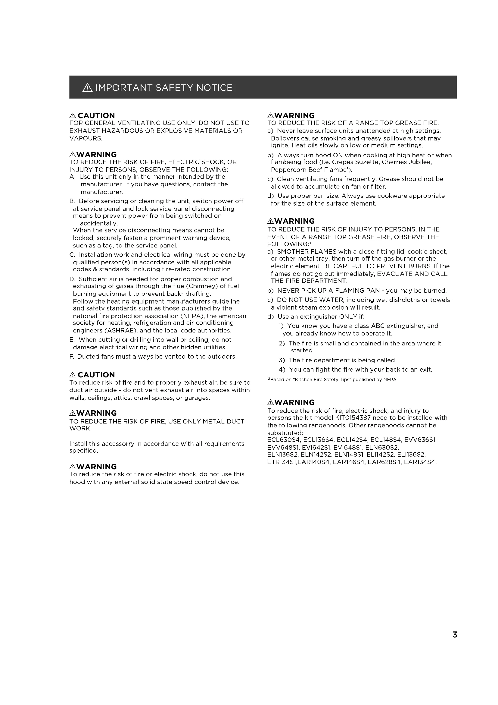
Product dimensions
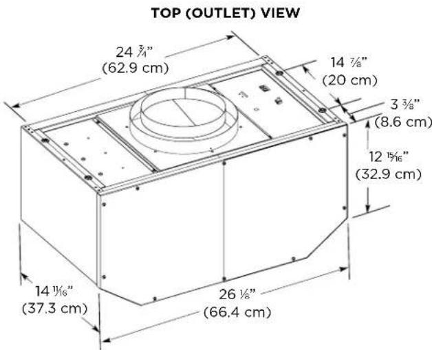
BOTTOM (INLET) VIEW
Venting Requirements
The vent system must terminate to the outdoors.
- Do not terminate the vent system in an attic or other enclosed area.
- Do not use 4'' (10.2 cm) laundry-type vent or wall caps.
- Use round, metal vent only. Rigid metal vent is recommended. Plastic or metal foil vent is not recommended.
- The length of the vent system and number of elbows should be kept to a minimum to provide efficient performance.
For the most efficient and quiet operation:
Use no more than three 90irc elbows.
Make sure there is a minimum of 24" (61.0 cm) of straight vent between the elbows if more than 1 elbow is used.
- Do not install 2 elbows together.
- Use clamps to seal all joints in the vent system.
The vent system must have a damper.
- Use weatherproof caulking to seal the exterior wall or roof opening around the cap.
The size of the vent should be uniform.
Cold weather installations
An additional backdraft damper should be installed to minimize backward cold air flow. A thermal break should be installed to minimize conduction of outside temperatures as part of the vent system. The damper should be on the cold air side of the thermal break.
The thermal break should be as close as possible to where the vent system enters the heated portion of the house.
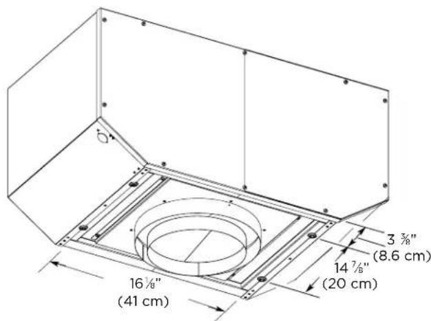
Typical In-line Blower System Installations
A 8'' (20.32 cm) - 10" (25.4 cm) round vent system is needed for installation (not included). The in-line blower system inlet and outlet openings are 8'' (20.32 cm) - 10" (25.4 cm) round. The exhaust (outlet) opening on the range hood must also be 8'' (20.32 cm) - 10" (25.4 cm) round.
NOTE: Flexible vent is not recommended. Flexible vent creates back pressure and air turbulence that greatly reduce performance.
The vent system can terminate either through the roof or wall.
NOTE: Plywood may be used as a mounting base to span open areas between ceiling joists and rafters. If used, be sure to use plywood capable of supporting the weight of the inline blower system (50 lb [22.6 kg]).
A. Mount on top of ceiling joists.
C. Duct horizontal; mount to cross-members tied to trusses.
B. Mount from cross-members tied to trusses.
D. Mount on underside of roof rafters.
E.Plywood
Electrical Requirements
Observe all governing codes and ordinances. Ensure that the electrical installation is adequate and in conformance with National Electrical Code, ANSI/NFPA 70 (latest edition), or CSA Standards C22.1-94, Canadian Electrical Code, Part 1 and C22.2 No. 0-M91 (latest edition) and all local codes and ordinances.
If codes permit and a separate ground wire is used, it is recommended that a qualified electrician determine that the ground path is adequate.
A copy of the above code standards can be obtained from:
National Fire Protection Association
One Batterymarch Park
Quincy, MA 02269
CSA International
8501 East Pleasant Valley Road
Cleveland, OH 44131-5575
- A 120 volt, 60Hz , AC only, 15-amp, fused electrical circuit is required.
If the house has aluminum wiring, follow the procedure below:
1 Connect a section of solid copper wire to the pigtail leads.
2 Connect the aluminum wiring to the added section of copper wire using special connectors and/or tools designed and UL listed for joining copper to aluminum.
Follow the electrical connector manufacturer's recommended procedure. Aluminum/copper connection must conform with local codes and industry accepted wiring practices.
- Wire sizes and connections must conform with the rating of the appliance as specified on the model/serial rating plate. The model/serial plate is located behind the kit on the rear wall.
Wire sizes must conform to the requirements of the National Electrical Code, ANSI/NFPA 70 (latest edition), or CSA Standards C22.1-94, Canadian Electrical Code, Part 1 and C22.2 No.0-M91 (latest edition) and all local codes and ordinances.
INSTALLATION INSTRUCTIONS
Prepare Location
Before making cutouts, make sure there is proper clearance within the ceiling or wall for the exhaust vent.
- When cutting or drilling into the ceiling or wall, do not damage electrical wiring or other hidden utilities.
- Check that all installation parts have been removed from the shipping carton.
NOTE: For the correct performance of your In-Line Blower System you must remove the Range Hood Internal Motor Blower.
Remove Range Hood Internal Motor Blower
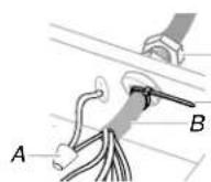
1 Remove grease filters from range hood.
2 Disconnect the blower power cord from de wire box.
A. Wire box connector
B. Power cord
A. For single Blower Motor Models (ECL630S4, EVV636S1, EVV648S1, EVI642S1, EVI648S1, ELN630S2, EAR628S4)
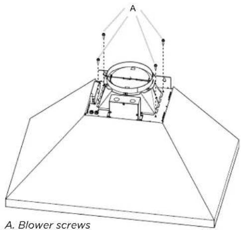
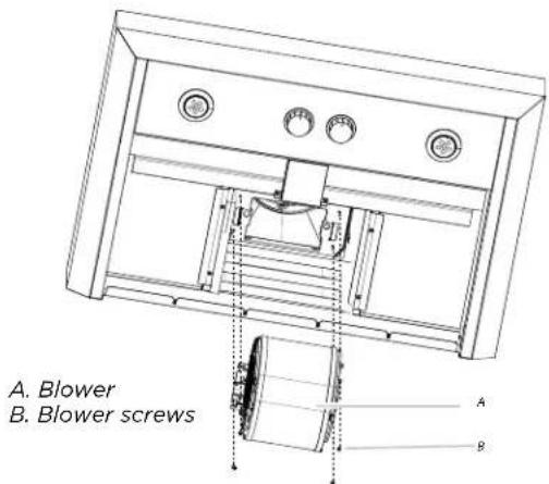
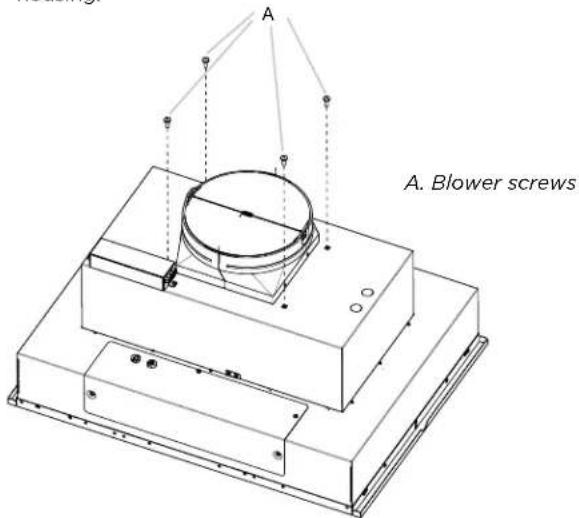
1 Remove the blower mounting screws.
NOTE: for ELN630S2 range hood model you have to remove the blower mounting screws from the top of the hood housing.
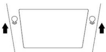
2 Set free the two blower springs from the top of the range hood housing.
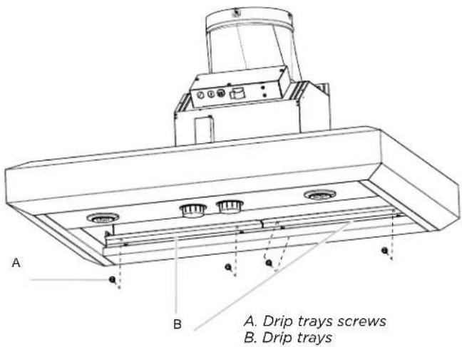
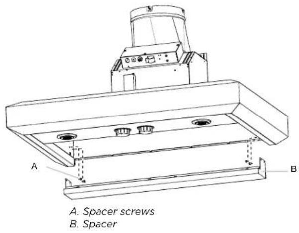
3 For or EVV648S1, EVV636S1 range hood models you have to remove the spacer and the dip trays before removing the internal motor blower.
4 Remove the range hood internal motor blower.
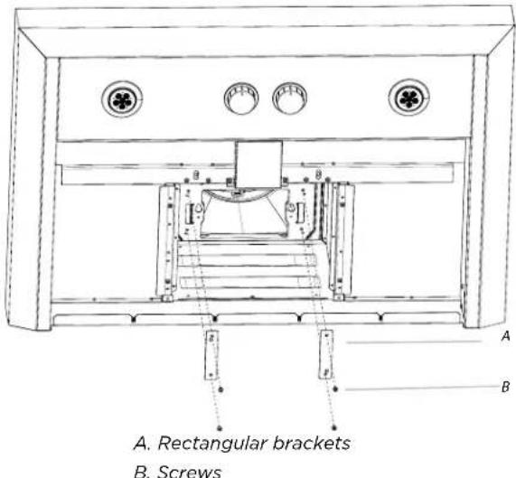
5 Install the rectangular brackets (included in kit) with screws (4) 4.2 × 8 mm.
6 Install the spacer, dip trays and grease filters.
B. For dual Blower Motor Models (ECL136S4, ECL142S4, ECL148S4, ELI142S2, ELI136S2, ETR134S1, EAR140S4, EAR146S4, EAR134S4, ELN136S2, ELN142S2, ELN148S1)
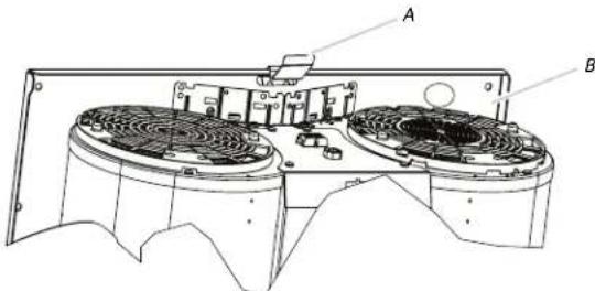
1 Remove the filters, the mounting screws and lock washers.
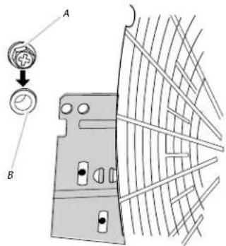
A. Screw with locker washer B. Mounting Hole
2 For ELN136S2, ELN142S2, ELI136S2, ELI142S2, EAR134S4 range hood models you have to remove the blower mounting screws from the top of the hood housing.
3 Remove the motor mounting plate by setting free the spring clip. NOTE: The spring clip should be outside the slot in the mounting plate.
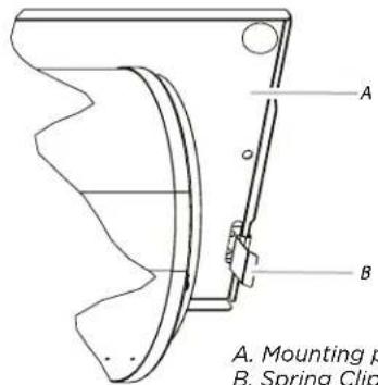
A. Mounting plate B. Spring Clip
A. Mounting plate B. Spring Clip
4 Run out the power supply wires and connector through the hole in the right end of the motor mounting plate.
5 Slide out the left mounting plate from under the motor mounting bracket.
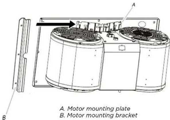
A.Motor mounting plate B.Motor mounting bracket
6 Install the grease filters.
Prepare for Mounting the In-Line Blower System The In-Line Blower System must be fastened to a secure structure of the roof, ceiling, wall, floor, or new or existing frame construction. The 4 holes on either the inlet (bottom) side or the outlet (top) side of the blower must be used to mount the in-line blower system to the structure.
NOTE: The mounting hole locations must span the studs. Additional stud framing may be required. Plywood may be used to span open areas between ceiling joists or roof rafters to aid installation. This structure must be strong enough to support the weight of the in-line blower system (50 lb [22.6 kg] min).
Prepare the In-line Blower System
WARNING
Excessive Weight Hazard Use two or more people to move and install range hood. Failure to do so can result in back or other injury.
1 Disconnect power.
2 Determine which venting method to use: roof or wall exhaust.
3 Using two or more people, move the in-line blower motor system to the mounting location.
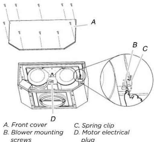
4 Remove the 10 screws from the front cover of the in-line blower motor housing and set them aside.
5 Remove the front cover of the in-line blower motor housing and set it aside.
NOTE: To make the in-line blower motor housing easier to mount, the blower motor assembly can be removed.
6 Disconnect the motor electrical plug from the blower motor assembly.
7 Remove the screws that secure the blower motor assembly to the in-line blower housing and set them aside.
8 Pull the spring clip to release the blower motor assembly. Remove the blower motor assembly from the housing and place it on a covered surface.
NOTE: The blower motor housing can be mounted using 4 holes from either the inlet side or the outlet side of the blower.
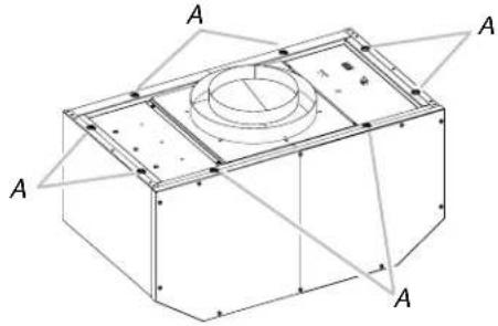
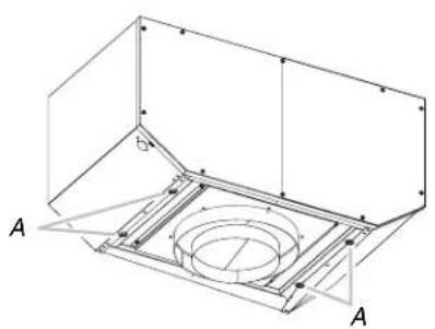
A. Mounting holes
1 Position the in-line blower motor housing in its mounting location and mark the 4 mounting hole locations.
2 Drill 4 mounting pilot holes using a 13 (0.5 cm) drill bit.
3 Attach the in-line blower motor housing to the mounting location with mounting (4) 6.3 × 60 mm screws and (4) 4 × 1.8 washers(Parts are included with the range hood motor kit)
4 If removed, reinstall the blower motor assembly and secure it with the screws previously removed.
5 If removed, reattach the motor electrical plug to the connector on the blower motor assembly.
Complete Preparation
1 Determine and make all necessary cuts for the vent system. IMPORTANT: When cutting or drilling into the ceiling or wall, do not damage electrical wiring or other hidden utilities.
2 Determine the location where the 12 (1.3 cm) wiring conduit will be routed through the ceiling or wall between the in-line blower and the range hood.
3 Drill a 114 (3.2 cm) hole at this location.
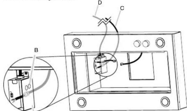
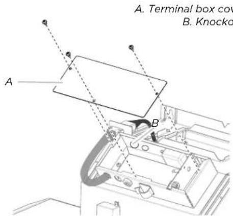
4 Locate the electrical terminal boxes in the in-line blower housing and range hood. Remove the terminal box covers and set the covers and screws aside.
A. Terminal Box Cover B. Knockout
5 Remove the electrical knockout from the in-line blower housing and range hood (see the range hood installation instructions) to prepare for the installation of the UL listed or CSA approved 12'' (1.3 cm) wiring conduit and conduit connector.
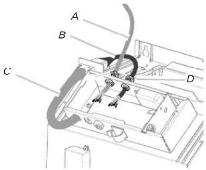
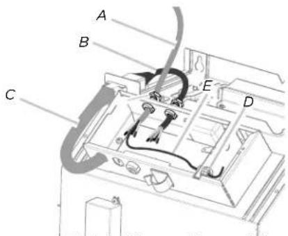
6 With the range hood mounted (see the range hood installation instructions), run the 12'' (1.3 cm) wiring conduit between the in-line blower motor housing and the range hood. Pull enough 12'' wiring conduit to allow for easy connection to the terminal boxes in the in-line blower housing and range hood.
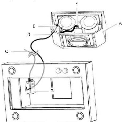
A. In-Line Blower Kit
B. Range Hood Terminal Box
C. Power Supply wiring Conduit
D. In-Line Blower Wiring Conduit (not included)
E. In-Line Blower Terminal Box
F. In-Line Motor Electrical Plug Cable
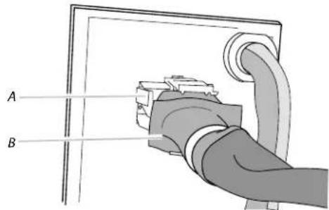
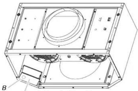
7 If necessary remove the range hood transition.
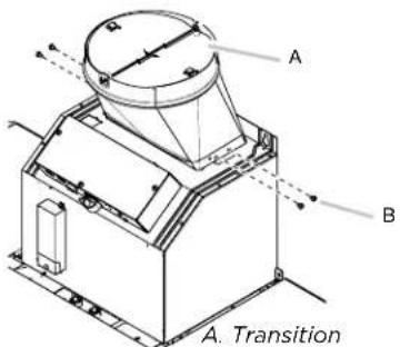
B. Transition screws
8 Install the conduit connectors and conduit to the in-line blower housing and range hood electrical terminal boxes.
NOTE: If removed, install the range hood transition.
9 Connect the vent system to the range hood and in-line blower system and seal all joints with clamps.
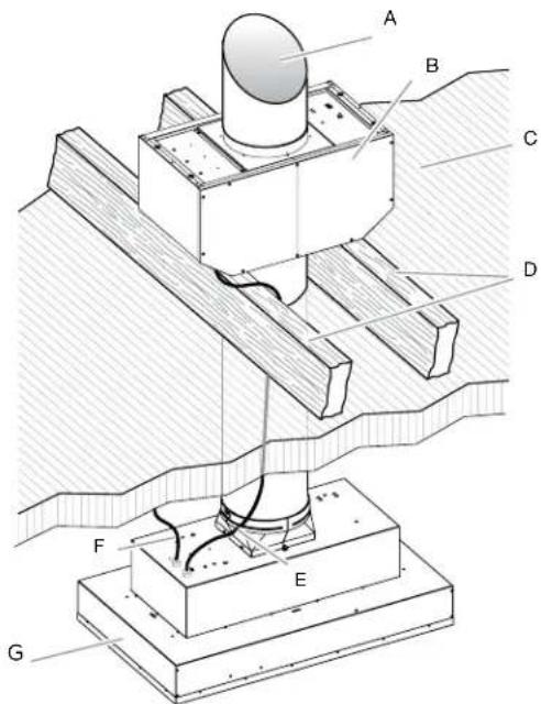
A. Vent System
B. In line Blower Motor
C. Ceiling
D. Roof rafters/ Plywood
E. In line Blower Wiring
Conduit (not included)
F. Power Supply Wiring
Conduit
G. Hood Insert
Make Electrical Connection for In-Line Blower Motor System
WARNING
Electrical Shock Hazard
Disconnect power before servicing.
Replace all parts and panels before operating.
Failure to do so can result in death or electrical shock.
WARNING
Electrical Shock Hazard
Electrically ground blower.
Connect ground wire to green and yellow ground wire in terminal box.
Failure to do so can result in death or electrical shock.
NOTE: The electrical diagram is attached at the end of the document.
Electrical Connection Inside In-line Blower System
1 Disconnect power.
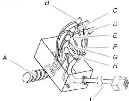
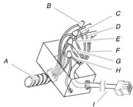
2 Connect the wires from the wiring conduit to the wires from the motor electrical plug cable inside the in-line blower housing terminal box.
3 Use UL listed wire connectors and connect the black wires (C) together.
4 Use UL listed wire connectors and connect the white wires (D) together.
5 Use UL listed wire connectors and connect the red wires (E) together.
6 Use UL listed wire connectors and connect the blue wires (F) together.
7 Use UL listed wire connectors and connect the gray wires (G) together.
8 Connect the green (or green/yellow) ground wire from the wiring conduit to the green (or yellow/green), ground wire (H) in the terminal box using UL listed wire connectors.
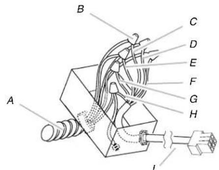
A. Strain relief
B. UL listed wire
connectors
C. Black wires
D. White wires
E. Red wires
F. Blue wires
G. Gray wires
H.Green (or yellow/
green) and green /
yellow wires
I. Motor electrical plug
cable
9 Once the connection is done, is necessary to adjust the 9-6 wire connector with the included strap.
D A. Ground wires
connection
C B.6-9 wire connector
C. Strap
D. Strain relief
10 Reinstall the in-line blower terminal box cover and screws.
11 Reinstall the front cover of the in-line blower housing and secure it with 10 mounting screws.
Make Electrical Connection Inside Range Hood Between In-Line Blower System and Range Hood
1 With the range hood mounted (see the range hood installation instructions), locate the wiring cable connector inside the range hood.
A. Range Hood Junction Box
B. Range Hood knockout for Wire Connector Assembly
C. Wire Connector Assembly (provided in the In-Line Blower Kit)
D. Power Supply Wiring Conduit
2 Connect the 6 wire connector assembly supplied with the in-line blower motor system to the mating connector from the range hood.
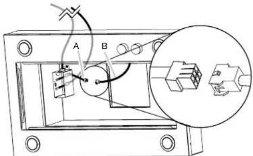
A. Wire Connector Assembly (provided in the In-Line Blower Kit)
B. Hood Insert Blower Connector
3 Install UL listed or CSA approved strain reliefs. Run through the strain reliefs the 6 wire connector and the In-Line Blower wiring conduit (not included leaving enough wire length to make the wiring connections.
4 Tighten the strain relief screws.
5 Connect the wires from the 6- wire connector assembly to the wires from the wiring conduit inside the range hood terminal box.
NOTE: Connect the green (or green/yellow) ground wire from the wiring conduit to the green (or bare) ground wire from the home power supply and to the and to the green/yellow ground wire from the 6-wire connector assembly (H) using UL listed wire connectors (see the "Make Electrical Power Supply Connections to Range Hood" section in the range hood installation instructions).
A. Strain relief
B. UL listed wire connectors
C. Black wires
D. White wires
E. Red wires
F. Blue wires
G. Gray wires
H. Green (or yellow/green) and green/yellow wires
I. Motor electrical plug cable
6 Connect the home power supply wiring to the range hood following the instructions that are supplied with the range hood.
7 Reinstall the range hood terminal box cover.
8 Reconnect power.
NOTE: For the Range Hood Models EVV636S1, EVV648S1, EVI642S1, EVI648S1 follow the next instructions.
NOTE: For the Range Hood Models EVV636S1, EVV648S1, EVI642S1, EVI648S1 use de 9 wire connector assembly and the 15.9mm strain relief.
1 With the range hood mounted (see the range hood installation instructions), locate the wiring cable connector inside the range hood.
2 Disconnect the Hood Insert Blower Connector.

3 Install the connector support bracket with screws (2)4.2x8mm included in kit; put the hood blower connector in the cavity of the bracket.
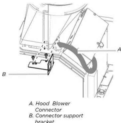
4 Connect the 9-wire connector assembly supplied with the in-line blower motor system to the mating connector from the range hood.
A.Hood Insert Blower Connector B.9 Wire Connector
5 Remove the screws and cover of the hood terminal box.
6 Remove the knockout from the top of the hood terminal box.
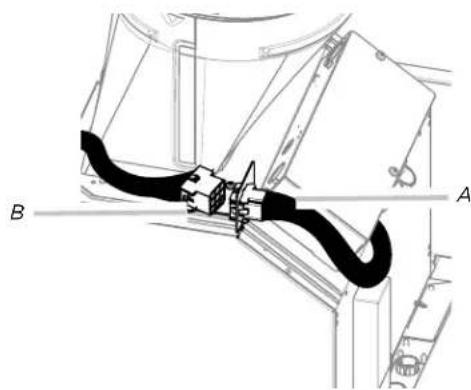
7 Install UL listed or CSA approved strain reliefs. Run through the strain reliefs the 9 wire connector and the In-Line Blower wiring conduit (not included leaving enough wire length to make the wiring connections.
8 Tighten the strain relief screws.
A. In-Line Blower wiring conduit (not included)
B. 6-9 wire connector
C. Hood Insert
Blower Connector
D. Strain reliefs
9 Remove the strain relief of the Range Hood terminal box, and run through the green (or green/yellow) ground wire from the wiring conduit. Install and tighten the removed strain relief.
A.In-LineBlowerwiringconduit (not included)
B. 6-9 wire connector
C. Hood Insert
Blower Connector
D. Range Hood strain relief
E. Strain relief
10 Connect the wires from the 9-wire connector assembly to the wires from the wiring conduit inside the range hood terminal box.
11 Connect the same color wires to each other (black to black, white to white, etc.) using UL listed wire connectors. NOTE: Connect the green (or green/yellow) ground wire from the wiring conduit to the green (or bare) ground wire from the home power supply and to the and to the green/yellow ground wire from the 9-wire connector assembly (H) using UL listed wire connectors (see the "Make Electrical Power Supply Connections to Range Hood" section in the range hood installation instructions).
A. Strain relief
B. UL listed wire connectors
C. Black wires
D. White wires
E. Red wires
F. Blue wires
G. Gray wires
H. Green (or yellow/green) and green/yellow wires
I. Motor electrical plug cable
12 Connect the home power supply wiring to the range hood following the instructions that are supplied with the range hood.
13 Reinstall the range hood terminal box cover.
14 Reconnect power.
TO OBTAIN SERVICE UNDER WARRANTY
Owner must present proof of original purchase date. Please keep a copy of your dated proof of purchase (sales slip) in order to obtain service under warranty.
PARTS AND SERVICE WARRANTY
For the period of two (2) years from the date of the original purchase, Elica will provide free of charge, non consumable parts or components that failed due to manufacturing defects. During these two (2) years limited warranty, Elica will also provide free of charge, all labor and in-home service to replace any defective parts.
WHAT IS NOT COVERED
- Damage or failure to the product caused by accident or act of God, such as, flood, fire or earthquake.
- Damage or failure caused by modification of the product or use of non-genuine parts.
- Damage or failure to the product caused during delivery, handling or installation.
- Damage or failure to the product caused by operator abuse.
- Damage or failure to the product caused by dwelling fuse replacement or resetting of circuit breakers.
- Damage or failure caused by use of product in a commercial application.
Service trips to dwelling to provide use or installation guidance. - Light bulbs, metal or carbon filters and any other consumable part.
Normal wear of finish. - Wear to finish due to operator abuse, improper maintenance, use of corrosive or abrasive cleaning products/pads and oven cleaner products.
WHO IS COVERED
This warranty is extended to the original purchaser for products purchased for ordinary residential use in North America (Including the United States, Guam, Puerto Rico, US Virgin Islands & Canada).
This warranty is non-transferable and applies only to the original purchaser and does not extend to subsequent owners of the product. This warranty is made expressly in lieu of all other warranties, expressed or implied, including, but not limited to any implied warranty of merchantability or fitness for a particular purpose and all other obligations on the part of Elica North America, provided, however, that if the disclaimer of implied warranties is ineffective under applicable law, the duration of any implied warranty arising by operation of law shall be limited to two (2) years from the date of original purchase at retail or such longer period as may be required by applicable law.
This warranty does not cover any special, incidental and/or consequential damages, nor loss of profits, suffered by the original purchaser, its customers and/or the users of the Products.
WHO TO CONTACT
To obtain service under warranty or for any service related question:
Elica North America Service, call at 18887328018
For Eastern Canada, call AGI Services at 1888 651 2534 Ask for the service department
- elica@servicepower.com
FRANÇAIS
Contents
ETR134S1,EAR140S4,EAR146S4,EAR628S4,EAR134S4.
Outils et pieces
Exigences concerning l'évacuation
National Fire Protection Association
One Batterymarch Park
Quincy, MA 02269
CSA International
8501 East Pleasant Valley Road
Cleveland, OH 44131-5575
Preparation complete
ETR134S1,EAR140S4,EAR146S4,EAR628S4,EAR134S4.
Lista de materiales
National Fire Protection Association,
1 Batterymarch Park
Quincy, MA 02169-7471
CSA International
8501 East Pleasant Valley Road
Cleveland, OH 44131-5575
Electrical Connection Inside In-line Blower System
B. 6-9 wire connector
C. Hood Insert
Blower Connector
D. Range Hood strain relief
- ENGLISH
- Contents
- APPROVED FOR RESIDENTIAL APPLIANCES
- READ AND SAVE THESE INSTRUCTIONS
- IMPORTANT SAFETY NOTICE
- CAUTION
- WARNING
- WARNING
- INSTALLATION REQUIREMENTS
- Tools and Parts
- Tools needed
- Parts needed
- Parts supplied
- Location Requirements
- For Mobile Home Installations
- Product dimensions
- Venting Requirements
- For the most efficient and quiet operation:
- Cold weather installations
- Typical In-line Blower System Installations
- Electrical Requirements
- INSTALLATION INSTRUCTIONS
- Prepare Location
- Remove Range Hood Internal Motor Blower
- Prepare the In-line Blower System
- Complete Preparation
- Make Electrical Connection for In-Line Blower Motor System
- Electrical Connection Inside In-line Blower System
- Make Electrical Connection Inside Range Hood Between In-Line Blower System and Range Hood
- TO OBTAIN SERVICE UNDER WARRANTY
- PARTS AND SERVICE WARRANTY
- WHAT IS NOT COVERED
- WHO IS COVERED
- WHO TO CONTACT
- FRANÇAIS
- Outils et pieces
- Exigences concerning l'évacuation
- Preparation complete
- Lista de materiales
Brand : ELICA
Model : Leone ELI142S1
Category : Air conditioner