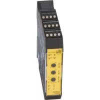
DD110S - Controller IFM - Free user manual and instructions
Find the device manual for free DD110S IFM in PDF.


User questions about DD110S IFM
0 question about this device. Answer the ones you know or ask your own.
Ask a new question about this device
Download the instructions for your Controller in PDF format for free! Find your manual DD110S - IFM and take your electronic device back in hand. On this page are published all the documents necessary for the use of your device. DD110S by IFM.
USER MANUAL DD110S IFM
Original operating instructions
Safe speed monitor
DD110S
Contents
1 Preliminary note.... 3
1.1 Manufacturer's address.... 3
1.2 Symbols used.... 3
1.3 Warnings.... 3
1.4 Safety symbol on the device 4
2 Safety instructions 5
2.1 General requirements on the safety-related functions 5
2.2 Cybersecurity.... 5
3 Transport, handling and storage 7
4 Intended use 8
5 Items supplied 9
6 Function 10
6.1 General function description.... 10
6.2 Safe state of the output relays (failsafe state).... 10
6.3 Switching function "Overspeed" 10
6.4 Hysteresis 11
6.5 Initialisation 11
6.6 Fault output (Y7) 11
6.7 Overspeed output (Y8).... 11
6.8 Feedback circuit for external device monitoring (Y1-Y2) 12
7 Installation.... 13
7.1 Removing the unit 14
8 Electrical connection 15
8.1 Terminals 15
8.2 Automatic/manual mode selection.... 16
8.2.1 Automatic operation.... 17
8.2.2 Manual operation 18
8.3 Enable inputs 19
9 Operating and display elements.... 21
9.1 LEDs 21
9.2 Switch 22
10 Set-up 23
10.1 Configuration position (factory setting) 23
10.2 Setting the switch point 23
10.3 Examples of switch point settings 24
10.4 Checklist after installation and set-up 24
10.5 Notes on sensor / damping element positioning 25
11 Technical data.... 27
11.1 DD110S.pdf 27
12 Maintenance, repair and disposal 31
12.1 Maintenance 31
12.2 Cleaning the housing surface 31
12.3 Repair 31
12.4 Disposal 31
1 Preliminary note
You will find instructions, technical data, approvals and further information using the QR code on the unit / packaging or at documentation.ifm.com.
1.1 Manufacturer's address
ifm electronic gmbh
Friedrichstraße 1
45128 Essen
Germany
www.ifm.com
info@ifm.com
1.2 Symbols used
√ Requirement
Instruction
Reaction, result
bold Designation of keys, buttons or indications
→ Cross-reference without link
→ Cross-reference with link
Important note Non-compliance may result in malfunction or interference
Information Supplementary note
1.3 Warnings
Warnings indicate the possibility of personal injury and damage to property. This enables safe product handling. Warnings are graded as follows:

WARNING
Warning of serious personal injury
▷ If the warning is not observed, fatal and serious injuries are possible.

CAUTION
Warning of minor to moderate personal injury
▷ If the warning is not observed, minor to moderate injuries are possible.

ATTENTION
Warning of damage to property
▷ If the warning is not observed, damage to property is possible.
1.4 Safety symbol on the device

Safety symbol on the device:
▶ Adhere to the operating instructions for the safe operation of the unit.
2 Safety instructions
- The unit described is a subcomponent for integration into a system.
- The system architect is responsible for the safety of the system.
- The system architect undertakes to perform a risk assessment and to create documentation in accordance with legal and normative requirements to be provided to the operator and user of the system. This documentation must contain all necessary information and safety instructions for the operator, the user and, if applicable, for any service personnel authorised by the architect of the system.
- Read this document before setting up the product and keep it during the entire service life.
- The product must be suitable for the corresponding applications and environmental conditions without any restrictions.
- Only use the product for its intended purpose (→ Intended use).
- If the operating instructions or the technical data are not adhered to, personal injury and/or damage to property may occur.
- The manufacturer assumes no liability or warranty for any consequences caused by tampering with the product or incorrect use by the operator.
- Installation, electrical connection, set-up, programming, configuration, operation and maintenance of the product must be carried out by personnel qualified and authorised for the respective activity.
- Protect units and cables against damage.
- Replace damaged units, otherwise the technical data and safety will be impaired.
- Observe applicable documents.
• After setup the system has to be subjected to a complete function check. - Disconnect the unit externally before handling it. Also, disconnect any independently supplied relay load circuits.
2.1 General requirements on the safety-related functions
The device complies with the functional and organisational requirements of EN ISO 13849-1 Performance Level "e" and EN 62061 SIL "3".

WARNING
To maintain Safety Integrity Level (SIL) "3" requirements the two input sensors must be independent.
Common cause failures between input sensors must be excluded by observing an appropriate cable installation (i.e. separate cable paths).
Input sensors must be mounted separately from each other.

WARNING
To maintain the requirements of Category 4 during extended periods of downtime, a level change must occur at the inputs (S43 and S34) at least every 24 hours.
2.2 Cybersecurity
Installation
The device is suitable for operation in a secure environment according to IEC 62443-1-1.
▶ Carry out a risk assessment of the system according to IEC 62443-1-1.
▶ Take measures to ensure physical security. The device has no built-in protection against unauthorised access.
3 Transport, handling and storage
▶ Store the device in its original packaging.
▶ When the device is to be stored again, use the original packaging or pack the device in suitable packaging.
▶ Observe the permissible ambient conditions for the device during storage (→ Technical data).

WARNING
Storage without sufficient protection for pollution degree 2
▷ Risk of electric shock when connecting the device
▶ Store the device in its original packaging.
▶ Otherwise, ensure pollution degree 2 for the device during storage.
4 Intended use
The device is an evaluation unit for fail-safe monitoring of speed and overspeed.
5 Items supplied
• 1 evaluation unit DD110S
• 1 original operating instructions DD110S
• CE declaration of conformity
▶ In the event of incomplete or damaged items supplied, please contact ifm.
6 Function
6.1 General function description
The device is a two-channel pulse evaluation system for safe overspeed detection. It receives the pulse sequences from the pulse pick-ups connected to the inputs. The device calculates the resulting frequency.
By continuously comparing the input frequency (actual value) and the switch point (limit value/switch point) the device promptly detects overspeed of the set switch point.
The NO contacts of the internal relays are connected in series, so the current paths are only closed once both relays have switched. By means of the current paths a door guard locking system can, for example, be controlled.

Fig. 1: Block diagram
The target value is set via 3 switches on the front of the device. The value can be set in rpm or Hz.
6.2 Safe state of the output relays (failsafe state)
Output relays are de-energised. Current paths are open.
6.3 Switching function "Overspeed"
The output relays de-energise when the event occurs (frequency Fo has been reached). The relays switch on again when the input frequency falls below the set target value reduced by the hysteresis (Foh).

Fig. 2: Characteristics of the safety outputs (current paths)
Fo: Frequency overspeed (= set switch point)
Foh: Frequency overspeed – hysteresis
6.4 Hysteresis
The hysteresis determines the difference between the switch point (current paths open) and the switch-on point (current paths close).
The hysteresis value is fixed at 5 %.
If the input frequency falls below the set switch point Fo by 5 %, the relays energise again and the current paths are closed.
Example switch point Fo = 10 (Hz):
- The current paths open when Fo is exceeded (rising frequency).
- The current paths close when Foh is not reached (here 9.5 Hz, falling frequency).
6.5 Initialisation
Directly after power on, the device carries out a complete self-test. This initialisation phase lasts approximately 3 seconds.
6.6 Fault output (Y7)
The transistor output "Fault" (Y7) opens when an internal or external error occurs.

The error message is reset by interrupting the voltage supply.
6.7 Overspeed output (Y8)
The overspeed output (Y8) is "HIGH" when the current paths are closed and "LOW" when the current paths are opened.
6.8 Feedback circuit for external device monitoring (Y1-Y2)
If overspeed is detected, the current paths open and the external relays are de-energised.
If the feedback circuit does not close within 1 s, an error message is provided. LED FAULT flashes 3 times (see: LINK LEDs).

If the feedback function is not required, the terminals Y1-Y2 must be permanently bridged.

Fig. 3: Feedback contacts (NC contacts of the external relays in series)
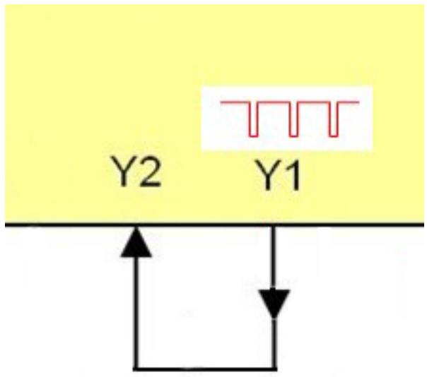
Fig. 4: Without feedback function with bridge
7 Installation
▶ Disconnect power.
To ensure correct operation, install the device in a housing that can only be opened using a tool or in a locked control cabinet (both protection rating IP 54 or higher) as an enclosure in accordance with EN61010-1.
For installation the requirements according to EN 60204 must be observed. Connect and lay all cables according to ENISO13849-2 D.5.2 (Safety of machinery - Safety-related parts of control systems).

Always comply with pollution degree 2 for the device.
▶ Install the device vertically on a 35 mm DIN rail.
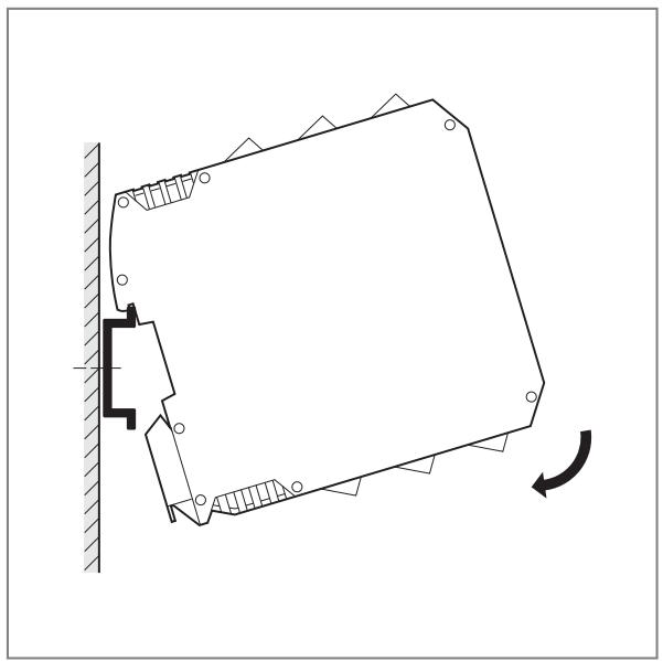
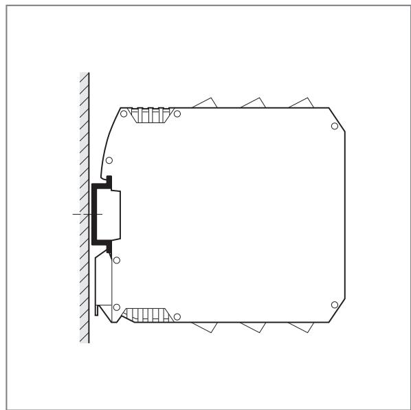
Leave enough space ( ≥ 50 mm) between the device and the top and bottom of the control cabinet to enable air circulation and to avoid excessive heating.

ATTENTION
If devices are mounted side by side, inadmissible heating may occur between the devices.
▷ Malfunction / damage is possible.
▶ Take into account the internal heating of all devices when mounting different devices side by side and observe the environmental conditions for each device.
It is recommended to maintain a minimum distance of 20mm between the devices.
7.1 Removing the unit

8 Electrical connection
8.1 Terminals

The unit must be connected by a qualified electrician.
▶ Observe the national and international regulations for the installation of electrical equipment.
▶ Disconnect power.
▶ Connect the unit as follows:
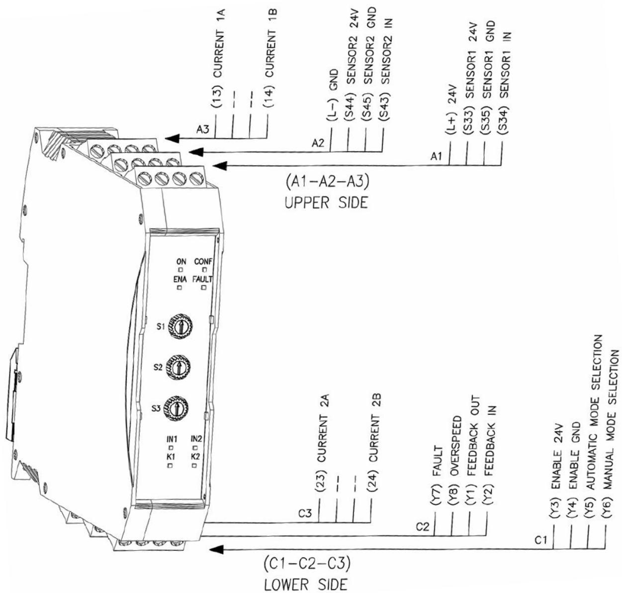
Fig. 5: Terminals
| Connector | Terminal | Connection |
| A1 | L+ | Supply voltage (+ 24 V DC) |
| S33 | Sensor 1 supply (+ 24 V DC) | |
| S35 | Sensor 1 GND (connected directly to L-) | |
| S34 | Sensor 1 input (PNP, debounced) | |
| A2 | L-S44 | Supply voltage (GND)Sensor 2 supply (+ 24 V DC) |
| S45 | Sensor 2 GND (connected directly to L-) | |
| S43 | Sensor 2 input (PNP, debounced) | |
| A3 | 13 | Current path 1A (relay contacts) |
| (not used) | ||
| (not used) | ||
| 14 | Current path 1B (relay contacts) | |
| C1 | Y3 | Deactivation of the monitoring function (P)(see Enable inputs ➕ 19) |
| Y4 | Deactivation of the monitoring function (N)(see Enable inputs ➕ 19) | |
| Y5 | Automatic mode selection | |
| Y6 | Manual mode selection | |
| C2 | Y7 | Transistor output "Fault"(see Fault output (Y7) ➕ 11) |
| Y8 | Transistor output "Overspeed"(see Overspeed output (Y8) ➕ 11) | |
| Y1 | Feedback circuit output | |
| Y2 | Feedback circuit input | |
| C3 | 23 | Current path 2A (relay contacts) |
| (not used) | ||
| (not used) | ||
| 24 | Current path 2B (relay contacts) |

The device's relay contacts must be supplied from the same voltage source.

Observe the technical data of the electrical connections (→ Technical data).

PELV power supplies are to be used according to EN 60204-1.
The electrical input signals meet the requirements to EN 61131, type 2.

Do not use unconnected terminals as support point terminals.
Terminal tightening torque: 0.6...0.7 Nm (5...7 lb-in)
8.2 Automatic/manual mode selection
If overspeed is detected, the current paths open and the drive is switched off. As a result the input frequency falls below the switch point and the current paths close (below Foh). The manual operation can prevent the current paths closing automatically as soon as the input frequency falls below the Foh value again.
The operating mode is selected via the circuitry of two input terminals Y5 and Y6.
8.2.1 Automatic operation

Fig. 6: Automatic operation
In this operating mode the device compares the input frequency with the set target value.
- If the input frequency is below the target value, the relay outputs are switched.
- If the input frequency exceeds the target value, the relay outputs are not switched.
The automatic operation mode is implemented by connecting input Y5 to Y1 (pulsed test signal) and input Y6 to +24 V DC.
The device goes into the failsafe state as soon as an error has been detected (short circuit at 0 V DC or +24 V DC or separated connections).
8.2.2 Manual operation
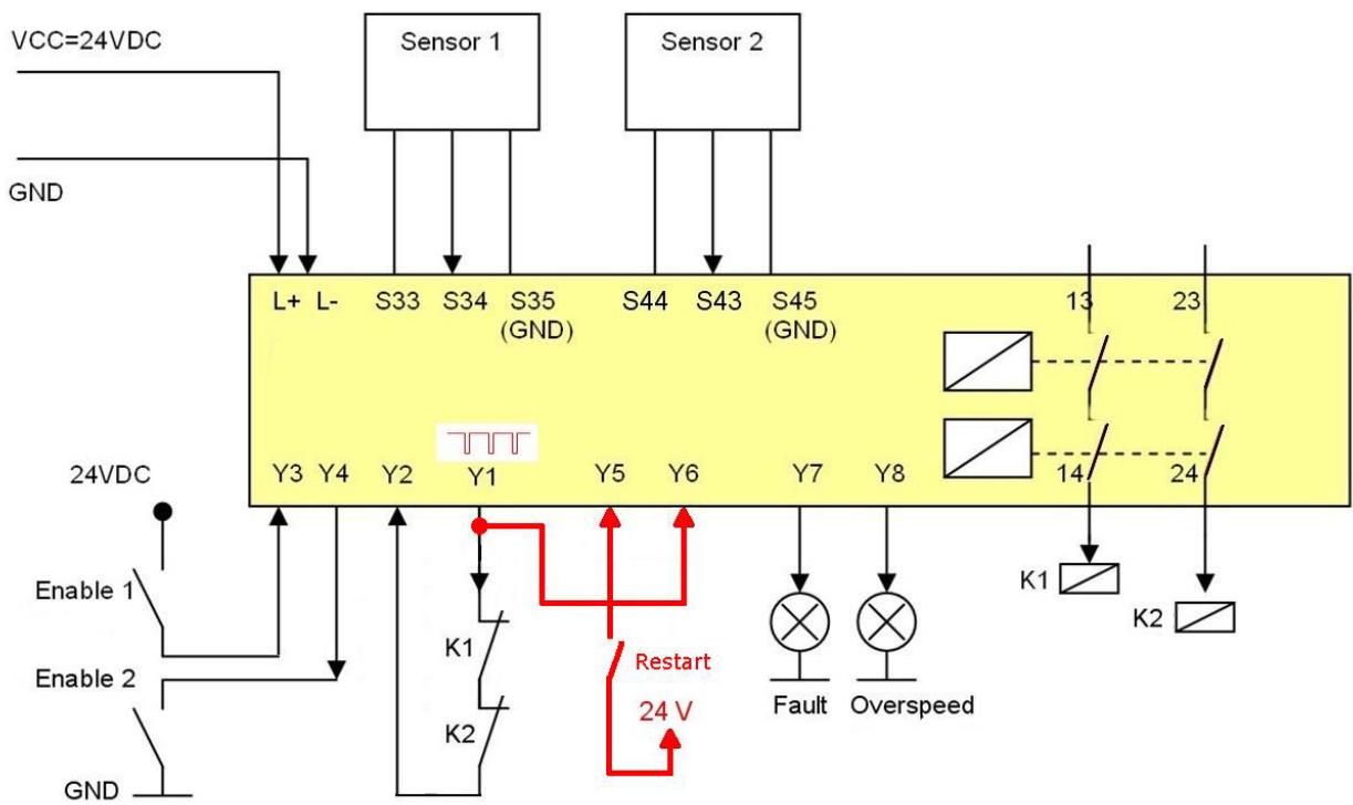
Fig. 7: Manual operation
In this operating mode, the outputs of the device are only activated if the input frequency is below the target value and after the restart signal has been sent to the device via an external restart command (terminal Y5).
Once the overspeed has been detected, the relay outputs are not switched.
The sequence described above must be repeated in order to re-activate them.
Manual operation is implemented when during initialisation input Y6 is on the pulsed test signal of Y1 and input Y5 is open. In this case the current path remains open until there is a restart signal on input Y5. The restart signal on input Y5 responds to the falling edge (a complete transition 0 V DC → +24 V DC → 0 V DC) of this input. This signal is only active when the frequency falls below the Foh value.

The restart signal must be applied for 0.3...5 s. Otherwise, the command is rejected.

If the restart command is activated while the frequency is between Fo and Foh, the command is rejected. This applies both to the rising and the falling edge.

The restart command element must be installed outside the hazardous area in a position where the hazardous area and the entire work area concerned are clearly visible.
The device may also be installed within the hazardous area since handling is not required during operation.
It must not be possible to operate the restart command element from inside the hazardous area.
When the device is waiting for the restart command, the yellow ENA LED flashes.
The figure below shows the restart options in the manual mode.
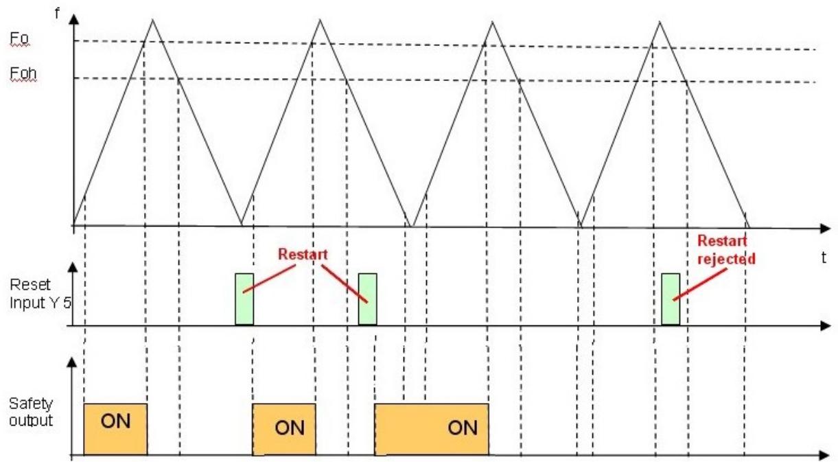
Fig. 8: Manual mode / restart diagram
8.3 Enable inputs
If several devices with different switch points are used for overspeed monitoring of a drive, devices whose switch point value is not relevant can be “switched off” by means of the two Enable inputs.
The monitoring function of these devices is then deactivated; the current paths are closed.
The monitoring function of a device is activated or deactivated by means of a complementary signal to both Enable inputs.

Fig. 9: Time-dependent behaviour of the Enable inputs (HIGH = switch closed, LOW = switch open)
1: The monitoring function of the device is active/not active
2: Enable signals not simultaneous

To deactivate the monitoring function of a device 2 conditions must be met:
- The Enable signals E1 and E2 have to be activated almost simultaneously. Max. time interval of the Enable signals: 0.5 s
- The device must be switched on when the Enable signals are activated.

The Enable signals can be activated by means of mechanical switches.
9 Operating and display elements
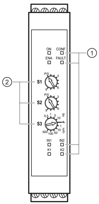
1: LEDs
2: Switches ( 270° potentiometer, 10 positions, locking)
9.1 LEDs
| LED | Colour | Description |
| ON | Green | PowerON when device is switched on. |
| CONF | Blue | ConfigurationON when device in configuration mode. Flashing when switches are in P position. |
| ENA | Yellow | EnableON when the enable inputs are logically on. Flashing in configuration mode when the position of a switch is changed (one flash for each step). Flashing when the device is waiting for a restart command (Manual operation). |
| FAULT | Red | ErrorON when an internal fault was detected. Flashing when an external fault was detected.1 x → Manual/automatic configuration error2 x → Switches in incorrect position (frequency selectors)3 x → Feedback circuit error4 x → Sensor error (function or wiring)5 x → Current > 500 mA on output S33, S44, Y1, Y7 or Y8 Flashing alternately with ENA, CONF, IN1/2 and K1/2 when a sensor is not connected.  |
| IN1/2 | Yellow | Input IN1/2ON when a HIGH signal was detected on the input IN1 or IN2. |
| K1/2 | Green | Relay K1/2ON when the safety output relay K1 or K2 is switched on. |
9.2 Switch
| Switch | Description | |
| S1 | SP x 10 | Switch point selection (increments of 10) |
| S2 | SP x 1 | Switch point selection (increments of 1) |
| S3 | SP multi | Unit (rpm/Hz) and multiplier of the selected switch point |
10 Set-up
When the device is switched on for the first time, it is necessary to configure the overspeed frequency (Fo) using the three switches.
• The numerical values 1 to 99 can be set with S1 and S2.
S1 with a step increment of 10, S2 with a step increment of 1.
• The multiplier is set with S3.
The numerical values are multiplied with these factors and thus provide the actual switch point value. The multipliers have the unit "rpm" or Hz".
10.1 Configuration position (factory setting)

Before the device is switched on for switch-point setting, the 3 switches must be in position "P" (factory setting).

The switch-point setting is only possible when the device is switched on.
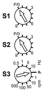
S1 in position P/0
S2 in position P/0
S3 in position P
Fig. 10: Configuration position (factory setting)

ATTENTION
To prevent damage to the switches use a screwdriver of the appropriate size.
10.2 Setting the switch point
Step 1:
▶ Switch off power supply of the device.
▶ Set the 3 switches to configuration position P or P/0 (Configuration position (factory setting) → 23)
▶ Switch on power supply of the device.
▷ Device is in the configuration mode.
▷ CONF LED flashes.
Step 2:
▶ Set switch S1 from the position P/0 to the required value.
▷ During the rotation, the ENA LED flashes with every switching step.
The flashing of the LED serves as visual feedback indicating that the switching step has been executed.
▷ Device remains in the configuration mode and waits for S2 to be set.
▷ The CONF LED is still flashing.
Step 3:
▶ Set switch S2 from the position P/0 to the required value.
▷ During the rotation, the ENA LED flashes with every switching step.
▷ Device remains in the configuration mode and waits for S3 to be set.
▷ The CONF LED is still flashing.
Step 4:
▶ Set switch S3 from the position P to the required value.
▷ During the rotation, the ENA LED flashes with every switching step.
▷ The CONF LED remains permanently on.
Step 5:
▶ Wait until the CONF LED flashes twice (settings are saved).
▶ Switch off power supply of the device.
▷ Configuration is completed.

All 3 switches must be moved at least once. This also applies if the required value is "0" (corresponds to the switching position P).
10.3 Examples of switch point settings
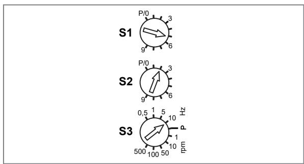
Fig. 11: 520 Hz

Fig. 12: 6700 rpm

The unit rpm is only applicable when 1 cam/revolution is present. For several cams: Multiply the required switch point by the number of cams.
Example: Required switch point: 1000 rpm Number of cams: 4 Setting value: 4 × 1000 rpm = 4000 rpm
10.4 Checklist after installation and set-up

Directly after power on, the device carries out an initialisation comprising a complete self-test. To ensure reliable operation of the device the following checks have to be performed on start-up and then at least once a year:
▶ Verify that all cables are correctly connected and the terminal blocks well screwed.
▶ Verify that all LEDs (indicators) light correctly.
▶ Verify the positioning of all connected sensors.
▶ Verify the correct fixing of the device to the DIN rail.
▶ Verify that all external indicators work correctly.
▶ Verify that the switches work correctly.
10.5 Notes on sensor / damping element positioning
The device checks whether the frequencies at the two inputs are identical (within the respective tolerances). Provided the direction of movement remains the same, the sensors can be positioned at any point within the damping zone.

Fig. 13: Example: direction of movement
In this case, the input signals look like this, for example:

Fig. 14: same frequency, time shift
In other cases, the position of the sensors or targets is crucial for correct operation. Otherwise, if the direction of movement changes, a sensor might not be damped, which would result in an error.
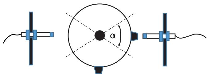
Fig. 15: Example: changing direction of movement, incorrect sensor positioning
If repeated movements occur within the specified angle, the two sensors detect different frequencies and the device will report an error. The device indicates this error by flashing the FAULT, IN1 and IN2 LEDs four times.

Fig. 16: No signal at IN1, error message at Y7
In this case, the problem can be resolved by repositioning the sensors or the targets so that the signals from both sensors are detected correctly.

Fig. 17: Example: changing direction of movement, correct sensor positioning
11 Technical data
11.1 DD110S.pdf
DD110S
Evaluation unit for safe speed monitoring
Safety speed monitor


1 screw terminals
2 rotary switch
3 mounting on DIN rail


Product characteristics
| Housing | rectangular | |
| Dimensions | [mm] | 108 x 22.5 x 114.5 |
| Safety-related switching outputs | ||
| Electrical design | relay; (Contacts potential-free) | |
| Digital output | ||
| Electrical design | PNP | |
| Output function | 1 x fault output "Fault"; 1 x Diagnostic output "Overspeed" | |
Application
| Design | housing for DIN rail mounting |
| Application | reliable evaluation of rotating and linear movements with regard to overspeed |
Electrical data
| Operating voltage | [V] | 19.2...28.8 DC; (incl. 5 % residual ripple) |
| Nominal voltage DC | [V] | 24 |
| Current consumption | [mA] | < 125 |
| Protection class | II | |
| Max. power-on delay time | [ms] | 3000 |
| Auxiliary energy for sensors DC | [V] | 24; (≤ 70 mA, voltage drop relative to the operating voltage ≤ 2 V) |
Inputs / outputs
| Number of inputs and outputs | Number of digital outputs: 2; Number of relay outputs: 2 |
DD110S
Evaluation unit for safe speed monitoring
Safety speed monitor

Inputs
| Input characteristics | S34, S43: "1": 6 mA / 24 V DC |
| Input circuit of digital inputs | PNP |
| Feedback circuit | |
| Current through feedback [mA] contacts | < 100 |
Outputs
| Number of digital outputs | 2 |
| Number of relay outputs | 2 |
| Feedback circuit | |
| Short-circuit proof | yes |
Safety-related switching outputs
| Electrical design | relay; (Contacts potential-free) |
| Contact rating | 6 A, 250 V AC / 24 V DC; ( ≥ 6 mA ; ohmic resistance) |
| Type of short-circuit protection | The contacts are to be protected by means of external fuses with a nominal current of < 3.6 A |
Digital output
| Electrical design | PNP |
| Output function | 1 x fault output "Fault"; 1 x Diagnostic output "Overspeed" |
| Max. current load per output [mA] | 20; (24 V DC, voltage drop relative to the supply voltage ≤ 2 V, non-safe) |
| Short-circuit proof | yes |
Measuring/setting range
| Setting range Hz | [Hz] | 0.5...990 |
| Setting range | [lmp/min] | 10...49500 |
| Frequency range | [Hz] | < 2000; (pulse duration: 100 μs: >500 Hz ; 150 μs: ≤ 500 Hz) |
Accuracy / deviations
| Hysteresis | [%] | 5 |
| Notes on the accuracy / deviation | Permitted frequency difference between the inputs: ≤ 10 % (f > 100 Hz) / ≤ 20 % (f < 100 Hz) |
Response times
| Response time to safety request [ms] | f sel ≥ 100 Hz: | t = 10,7 + 400 x (f sel ÷ f in) |
| f sel < 100 Hz: | t = 14 + (4500 ÷ f in) | |
| Risk time (response time for safety-related faults) [ms] | 5.5 | |
| Legend | t : | Response time |
| f sel : | set frequency (preset value) | |
| f in : | applied frequency (actual value) | |
Operating conditions
| Ambient temperature | [°C] | -40...55 |
| Note on ambient temperature | observe the free space for convection (see operating instructions) | |
| Storage temperature | [°C] | -40...70 |
| Max. relative air humidity | [%] | 95 |
| Max. height above sea level | [m] | 2000 |
| Protection | IP 20 |
ifm electronic gmbh • Friedrichstraße 1 • 45128 Essen — EN-GB — DD110S — 16.04.2026 —
DD110S
Evaluation unit for safe speed monitoring
Safety speed monitor

| Safety classification | |||
| Complies with the requirements | ISO 13849-1 category 4, PL e | ||
| IEC 61508 SIL 3 | |||
| Mission time TM [h] | ≤175200 | ||
| Mission time TM (additional indication) | 20 years | ||
| PFH [1/h] | DC13 (2 A), 24 V DC | 7,69E-09 | |
| AC15 (1 A), 230 V AC | 8,25E-09 | ||
| AC15 (3 A), 230 V AC | 9,15E-09 | ||
| Hardware fault tolerance HFT | 1; (Type B) | ||
| Mechanical data | |||
| Weight [g] | 309 | ||
| Housing | rectangular | ||
| Type of mounting | mounting on DIN rail; (TH35 (EN 60715)) | ||
| Dimensions [mm] | 108 x 22.5 x 114.5 | ||
| Materials | housing: PA | ||
| Displays / operating elements | |||
| Display | Voltage | 1x LED, green | |
| release | 1x LED, yellow | ||
| configuration | 1x LED, blue | ||
| error | 1x LED, red | ||
| switching status | 2x LED, green | ||
| input signal | 2x LED, yellow | ||
| Remarks | |||
| Remarks | characteristic safety values for 1000 relay actuations / year | ||
| Pack quantity | 1 pcs. | ||
| Electrical connection | |||
| screw terminals: 0.5...2.5 mm2; AWG 30...12 | |||
| A1 | |||
| 1 (L+) | L+ | ||
| 2 (S33) | L+ | (US; Sensor supply) | |
| 3 (S35) | L- | (US; Sensor supply) | |
| 4 (S34) | IN | FI | |
| A2 | |||
| 1 (L-) | L- | ||
| 2 (S44) | L+ | (US; Sensor supply) | |
| 3 (S45) | L- | (US; Sensor supply) | |
| 4 (S43) | IN | FI | |
| A3 | |||
| 1 (13) | OUT1 | DO1 (NO) (relay) | |
| 2 (n.c.) | n.c. | ||
| 3 (n.c.) | n.c. | ||
| 4 (14) | OUT2 | DO2 (NO) (relay) | |
| C1 | |||
| 1 (Y3) | IN1 | DI1 (PNP) | |
| 2 (Y4) | IN2 | DI2 (NPN) | |
| 3 (Y5) | IN3 | DI3 | |
| 4 (Y6) | IN4 | DI4 | |
ifm electronic gmbh • Friedrichstraße 1 • 45128 Essen — EN-GB — DD110S — 16.04.2026 —
DD110S
Evaluation unit for safe speed monitoring
Safety speed monitor

C2
| 1 (Y7) | OUT1 | DO1 |
| 2 (Y8) | OUT2 | DO2 |
| 3 (Y1) | OUT3 | DO3 |
| 4 (Y2) | IN | DI |
C3
| 1 (23) | OUT1 | DO1 (NO) (relay) |
| 2 (n.c.) | n.c. | |
| 3 (n.c.) | n.c. | |
| 4 (24) | OUT2 | DO2 (NO) (relay) |
| DI: digital input; DO: digital output; FI: frequency input | ||
ifm electronic gmbh • Friedrichstraße 1 • 45128 Essen — EN-GB — DD110S — 16.04.2026 —
12 Maintenance, repair and disposal
12.1 Maintenance
The unit is maintenance-free.
12.2 Cleaning the housing surface
▶ Disconnect the device from the voltage supply.
▶ Clean the device from dirt using a soft, chemically untreated and dry micro-fibre cloth.
12.3 Repair
▶ The device must only be repaired by the manufacturer. Observe the safety instructions (→ Safety instructions).
▶ Contact ifm in case of malfunction.
12.4 Disposal
▶ After use, dispose of the unit in an environmentally friendly way in accordance with the applicable national regulations.


- 1 PRELIMINARY NOTE
- 1.1 MANUFACTURER'S ADDRESS
- 45128 ESSEN
- 1.2 SYMBOLS USED
- 1.3 WARNINGS
- 1.4 SAFETY SYMBOL ON THE DEVICE
- 2 SAFETY INSTRUCTIONS
- 2.1 GENERAL REQUIREMENTS ON THE SAFETY-RELATED FUNCTIONS
- 2.2 CYBERSECURITY
- 3 TRANSPORT, HANDLING AND STORAGE
- 4 INTENDED USE
- 5 ITEMS SUPPLIED
- 6 FUNCTION
- 6.1 GENERAL FUNCTION DESCRIPTION
- 6.2 SAFE STATE OF THE OUTPUT RELAYS (FAILSAFE STATE)
- 6.3 SWITCHING FUNCTION "OVERSPEED
- 6.4 HYSTERESIS
- 6.5 INITIALISATION
- 6.6 FAULT OUTPUT (Y7)
- 6.7 OVERSPEED OUTPUT (Y8)
- 6.8 FEEDBACK CIRCUIT FOR EXTERNAL DEVICE MONITORING (Y1-Y2)
- 7 INSTALLATION
- 7.1 REMOVING THE UNIT
- 8 ELECTRICAL CONNECTION
- 8.1 TERMINALS
- 8.2 AUTOMATIC/MANUAL MODE SELECTION
- 8.2.1 AUTOMATIC OPERATION
- 8.2.2 MANUAL OPERATION
- 8.3 ENABLE INPUTS
- 9 OPERATING AND DISPLAY ELEMENTS
- 9.1 LEDS
- 9.2 SWITCH
- 10 SET-UP
- 10.1 CONFIGURATION POSITION (FACTORY SETTING)
- 10.2 SETTING THE SWITCH POINT
- 10.3 EXAMPLES OF SWITCH POINT SETTINGS
- 10.4 CHECKLIST AFTER INSTALLATION AND SET-UP
- 10.5 NOTES ON SENSOR / DAMPING ELEMENT POSITIONING
- 11 TECHNICAL DATA
- 11.1 DD110S.PDF
- 12 MAINTENANCE, REPAIR AND DISPOSAL
- 12.1 MAINTENANCE
- 12.2 CLEANING THE HOUSING SURFACE
- 12.3 REPAIR
- 12.4 DISPOSAL
Brand : IFM
Model : DD110S
Category : Controller