
D570 - Ice machine Manitowoc - Free user manual and instructions
Find the device manual for free D570 Manitowoc in PDF.

User questions about D570 Manitowoc
0 question about this device. Answer the ones you know or ask your own.
Ask a new question about this device
Download the instructions for your Ice machine in PDF format for free! Find your manual D570 - Manitowoc and take your electronic device back in hand. On this page are published all the documents necessary for the use of your device. D570 by Manitowoc.
USER MANUAL D570 Manitowoc
natural_image
Exterior view of a modern stainless steel ice cream refrigerator with open vent (no visible text or symbols)S Model Dispensers
Installation, Use & Care Manual
This manual is updated as new information and models are released.
Visit our website for the latest manual. www.manitowocice.com
This manual contains English and French text
Table of Contents
Section 1
General Information
Read This Manual 4
Model Numbers 4
Accessories 4
Adapter Kits 4
Included Baffle Kit 4
Earthquake Kits 4
Serial Plate Location 4
Section 2
Installation Instructions
Pre-Installation Checklist 5
Electrical 6
Specifications 6
Grounding Instructions 6
Installation Procedures 7
Installation Checklist 7
Section 3
Operation
Sequence of Operation 8
Dispenser Activation 8
Ice Pick-Up 8
Ice Delivery 8
Room Key Card Activation 9
Coin Operated Activation 9
Adjustments 9
Adjusting the Coin Mechanism Timer 9
Adjusting the Coin Mechanism for Canadian Coins 9
Agitation Timers 10
Timer with Blinking LED 10
Timer with Test Pins 10
Section 4
Maintenance
Disassembly 11
Removing the Front Panel 11
Removing the Drain Pan 11
Disassembling the Rocking Chute/Door & Paddle Wheel Guard 12
Disassembling the Dispenser Parts for Bin Cleaning 13
Cleaning and Sanitizing 14
Monthly Sanitizing Procedure 14
Assembly 14
Re-Installing the Paddle Wheel Guard 14
Removal of the Gearmotor 15
Table of Contents (continued)
Section 5 Customer Support
Checklist 16
Problem: Ice Does Not Dispense When Rocking Chute Is Depressed ..... 16
Problem: Dispenser Crushes Ice as it Dispenses 16
Problem: Ice Continues to Dispense or Dispenses by Itself 16
Ice Machine Warranty 17
Section 1
General Information
Read This Manual
These instructions are provided to assist the qualified installer. Check your local Yellow Pages for the name of the nearest Manitowoc distributor, or call Manitowoc Foodservice; for information regarding start-up services.
Model Numbers
This manual covers the following models:
| Series | Rocking Chute Operated | Card Operated | Coin Operated | Glass Fill Dispenser |
| S160 SP | A160 SRA164 | SCA163 N/A | ||
| S190 N/A | N/A N/A SFA191 | |||
| S290 N/A | N/A N/A SFA291 | |||
| S300 SP | A310 SRA340 | SCA330 N/A |
These dispensers are designed to dispense both dice and half dice ice. These dispensers are used in conjunction with a Manitowoc ice machine for automatic fill of dispenser.
- S160/S190 Series Dispensers are capable of storing 120 lbs. of ice. The S160/S190 accepts a single 22" Dice or Half Dice size ice machine.
- S290/S300 Series Dispensers are capable of storing 180 lbs. of ice. The S290/S300 accepts a single 22" or 30" Dice or Half Dice size ice machine, except Series S1000 and S1200, which are not approved for use on an S Model Dispenser.
NOTE: Dispense Opening: Height 11" (28 cm), Width 14" (36 cm)
Accessories
ADAPTER KITS
22" ice machines mounted on a 30" dispenser require two adapter kits (not included with dispenser):
- K00365 adapter allows 22" ice machine to be mounted on a 30" bin.
- K00348 baffle prevents ice from contacting the ice machine front panel.
INCLUDED BAFFLE KIT
S Model 22" & 30" Ice Machines require installation of the included baffle 5029517 (22") or K00346 (30"). This baffle prevents ice from contacting the ice machine front panel.
EARTHQUAKE KITS
Earthquake kits are available to secure the ice machine to the dispenser and the dispenser to the floor.
Serial Plate Location
Front of Dispenser — Label with Model Number and Serial Number is located behind the front panel, to the right of the rocking chute.
Back of Dispenser — A second location for the Model Number and Serial Number is on the back of the dispenser, in the upper right corner.
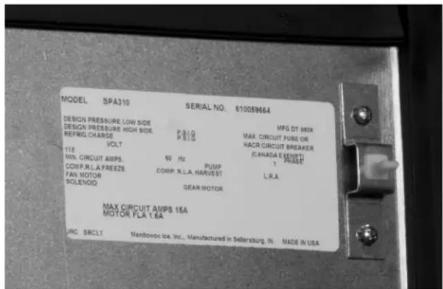
text_image
MODEL SPA310 SERIAL NO. 610059664 MFG DT 0808 DESIGN PRESSURE LOW SIDE P.S.I.G DESIGN PRESSURE HIGH SIDE P.S.I.G REFRIQ CHARGE VOLT 115 MIN. CIRCUIT AMPS. 60 Hz PUMP COMP.R.L.A.FREEZE COMP.R.L.A.HARVEST L.R.A. FAN MOTOR SOLENOQ GEAR MOTOR MAX CIRCUIT AMPS 15A MOTOR PLA 1:6A LIRC SRCLT Manitowoc Ice, Inc., Manufactured in Sellersburg, IN. MADE IN USAFront Panel Location
Section 2 Installation Instructions
Pre-Installation Checklist
☐ Location: Floor drain available – A floor drain for the dispenser should be available. We recommend that you vent the drain at the back of the dispenser to reduce buildup of algae and improve drainage. Drain tubing should be 1/2" I.D. at minimum.
☐ Location: Avoid heat sources – Avoid placing the ice machine near heat sources such as radiators, heating vents and direct sunlight. Avoid placing air-cooled ice machines in kitchens, due to grease, flour, or other particles, which can collect on the condenser and fan blade, increasing ice machine maintenance and reducing ice machine efficiency.
☐ Location: On a solid floor – The dispenser and ice maker should be sitting on a good, solid, level floor or surface.
☐ Location: Do not obstruct traffic – The dispenser should not extend from the wall in a way that obstructs traffic through the area.
Electrical – Proper electrical voltage is available. Receptacle is available and within six feet.
Warning
Never use an extension cord. If an electrical outlet is not within six feet, have proper amperage outlet installed. The dispenser must be grounded in accordance with all local and national electrical codes.
Clearances for top and both sides of ice machine – Use clearances specified in the ice machine's Installation, Use and Care Manual.
☐ Clearance behind ice machine for dispenser and drains – The location must allow enough clearance for the water and drain connection at the rear of the dispenser.
Back of ice machine to be flush with back of dispenser – This allows installation of the supplied mounting clip (metal plate) which secures the ice machine to the dispenser.
Separate drains – a separate drain line is required for the ice machine, in addition to a drain line for the S Series Dispenser. Vent all drain lines.
Water filtration – Water filtration is strongly recommended in order to increase the performance of the ice machine and reduce maintenance costs.
For full information about ice machine installation, including plumbing lines, connections and electrical requirements, see the ice machine installation manual.
Caution
The dispenser must be protected if it will be subjected to temperatures below 32^ F ( 0^ C). Failure caused by exposure to freezing temperatures is not covered by the warranty.
Electrical

Warning
All wiring must conform to local, state and national codes.
SPECIFICATIONS
| Electric Voltage – Cycle – Amp.* | 120 Volt – 60 Hz./1 Ph. – 1.8 amp |
| 230 Volt – 50/60 Hz./1 Ph. – 0.6 amp | |
| Motor Horsepower | 1/10 HP |
| Fuse Size 15 amp maximum | |
| Ship Weight 187 pounds | |
| Operating Temperature Range | 40°F minimum – 110°F maximum (4° – 43°C) |
*120 Volts – 60 Hz. – 1.8 amp (U.S. Standard) (Eight foot cord with plug is included with the U.S. Standard unit)
Grounding Instructions

Warning
The dispenser must be grounded in accordance with national and local electrical codes.
This appliance must be grounded. In the event of malfunction or breakdown, grounding provides a path of least resistance for electric current to reduce the risk of electric shock. This appliance is equipped with a cord having an equipment-grounding conductor and a grounding plug. The plug must be plugged into an appropriate outlet that is properly installed and grounded in accordance with all local codes and ordinances.

Warning
Improper connection of the equipment-grounding conductor can result in a risk of electric shock. The conductor with insulation having an outer surface that is green with or without yellow stripes is the equipment grounding conductor. If repair or replacement of the cord or plug is necessary, do not connect the equipment-grounding conductor to a live terminal. Check with a qualified electrician or serviceman if the grounding instructions are not completely understood, or if in doubt as to whether the appliance is properly grounded. Do not modify the plug provided with the appliance — if it will not fit the outlet, have a proper outlet installed by a qualified electrician.
Water Supply and Drains
POTABLE WATER
- Water temperature must be between 40^ (4.4°C) and 90^ (32°C).
• Water pressure must be between 20 psi (140 kPa) and 80 psi (550 kPa). - Minimum internal diameter of tubing 3/8" (10 mm).
DRAIN CONNECTIONS
- Drain lines must have a 1.5 inch drop per 5 feet of run (2.5 cm per meter) and must not create traps.
- The floor drain must be large enough to accommodate drainage from all drains.
- Run separate bin and ice machine drain lines.
• Insulate drain lines to prevent condensation. - Vent the ice machine drain to the atmosphere.
- Drain termination must have an air gap that meets local code.
Installation Procedures

Warning
Do not attempt to move a dispenser without first removing the ice machine. The combination can be unstable and could tip, causing serious injury.
- Review the Pre-Installation Checklist; then make sure all utility and space requirements are present at the installation site.
- Remove the carton top from the dispenser.
- Remove the legs and other accessories from inside the dispenser bin.
- Remove the carton from the sides of the dispenser.
- Remove the dispenser from the shipping pallet.
- Flatten the shipping carton.
- Lay the dispenser on its back; on the carton.
- Thread the legs into the bottom of the dispenser.
- Set the dispenser upright.
- Place the dispenser in the desired location.
- Make sure the dispenser bin top is level. A level bin is important for proper operation of the ice machine.
- Place the ice machine on top of the dispenser at this time.
- Connect the drain of the dispenser to the floor drain.
- Follow local plumbing codes for drain installation.
- If the dispenser has a water valve, connect your water line to the water connection at the back of the dispenser.
- Test all drain and water lines for leaks.
- Plug the dispenser into the proper electrical outlet.
- Clean and sanitize all equipment. Follow cleaning and sanitizing instructions in this manual.
- Adjust the ice machine according to the instructions provided with the ice machine.
- Install ice baffle inside the ice maker compartment. Follow installation instructions supplied with ice baffle.
- Install foam gasket on the bottom of the front panel.
- Fill the dispenser bin one quarter full of ice or start the ice machine, allowing the ice machine to drop at least three complete batches of ice.
- Test the ice dispensing action of the dispenser.
Installation Checklist
☐ Dispenser and ice machine are level?
Drains are vented?
☐ Dispenser does not sit in direct sunlight?
☐ Dispenser does not sit in direct airflow from a heating duct?
Bin and ice machine drains are separate?
Ice dispensed properly?
☐ Dispenser is accessible for servicing?
The warranty card was returned?
Ice Machine ice thickness control is properly set?
Owner was instructed on the operation of the dispenser?
Owner knows how to clean and sanitize the dispenser?
☐ Owner knows how often to clean and sanitize the dispenser?
Owner has your telephone number to call for follow-up service on the dispenser?
☐ You have placed one of your service stickers on the dispenser for follow-up service?
Section 3
Operation
Sequence of Operation
The operation of the S Series ice dispenser can be divided into three main operations. They are Dispenser Activation, Ice Pick-Up and Ice Delivery.
DISPENSER ACTIVATION
Dispenser activation can be accomplished with a number of different mechanisms.
- Rocking Chute (Push for Ice) Activation – User pushes the Rocking Chute, which energizes a microswitch. The energized microswitch engages the gearmotor.
- Room Key Card Activation – User places their hotel room key card into a slot on the dispenser. The room key card activates the microswitch. The user then presses the Rocking Chute (Push for Ice) for ice dispense. This action activates the gearmotor.
- Coin Operated Activation – User places one quarter into dispenser. The quarter activates the coin mechanism. The user then presses the Rocking Chute (Push for Ice) for ice dispense. This action activates the gearmotor.
DANGER
Do not operate equipment that has been misused, abused, neglected, damaged, or altered/modified from that of original manufactured specifications. This appliance is not intended for use by persons (including children) with reduced physical, sensory or mental capabilities, or lack of experience and knowledge, unless they have been given supervision concerning use of the appliance by a person responsible for their safety. Do not allow children to play with, clean or maintain this appliance without proper supervision.
ICE PICK-UP
When the customer activates the dispenser, the gearmotor inside the dispenser begins to turn.
The gearmotor shaft is attached to the paddle wheel inside the bin of the dispenser. As the paddle wheel turns it picks up ice from the dispenser bin. The paddle wheel will bring the pocket containing the ice to the top of the travel area.
ICE DELIVERY
When the paddle wheel pocket reaches the top of its travel, the ice falls from the paddle wheel to the ice chute opening of the dispenser bin. The bin chute then directs the ice to the door assembly dispensing 2-3 oz. of ice per second.
If the door closes before all the ice is dispensed, some ice may be held back by the door assembly. If the door is open, the ice will fall through the door and the ice chute. The ice chute will direct the ice into the customer's container.
NOTE: Dispense Opening: Height 11" (28 cm), Width 14" (36 cm)
Model SFA-191/291 is equipped with an optional water valve. When the water valve lever is pressed, water flows through the system to the water valve nozzle.
Room Key Card Activation
- User places ice bucket under ice chute.
- User places their hotel room key card into a slot on the dispenser which is labeled "Insert Room Key Card". The room key activates the microswitch.
- The user then presses the Rocking Chute (Push for Ice) for ice dispense. Pushing the ice chute activates the gearmotor.
The room key card must stay in the slot for the microswitch to remain activated.
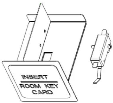
text_image
INSERT ROOM KEY CARDCoin Operated Activation
- User places ice bucket under ice chute.
- User places one quarter (U.S. currency only) into dispenser.
- The user then presses the Rocking Chute (Push for Ice) for ice dispense.
Pushing the ice chute activates the gearmotor. Ice will dispense for up to one minute for each 25 cent activation per factory setting.
Important
Coin Operated Activation will accept U.S. quarters only. No other coin is accepted and no change is returned to the user. To allow use of Canadian coins refer to instructions in this manual.
Adjustments
ADJUSTING THE COIN MECHANISM TIMER
- Remove the control box cover. On the inside of the control box there is a white instruction label which shows how to set intervals for coin mechanism dispense times.
- Inside the control box, the coin mechanism timer is to the left. The ice agitation timer is to the right.
- With a small Phillips head screwdriver, adjust the coin mechanism timer. For timer adjustment reference information, see below or refer to the white instruction label inside the control box cover.
- The timer is factory set at the midpoint for 60 seconds of dispense time. The adjustment pot can be set (counterclockwise) for as low as 12 seconds of dispense time. The adjustment pot can be set (clockwise) for as high as 120 seconds of dispense time.
ADJUSTING THE COIN MECHANISM FOR CANADIAN COINS
Important
Canadian quarters are magnetic. Therefore the magnet inside the coin mechanism must be removed so Canadian quarters will drop through the coin mechanism.
- Remove the front panel of the dispenser. The coin mechanism can be changed while in place in the dispenser door, as shown above.
- Pivot the coin magnet housing section away from the rest of the coin mechanism.
- Using a small screwdriver, loosen the set screw which holds an aluminum plate in the coin magnet housing.
- Remove the aluminum plate.
- Using a metal screwdriver tip, pull out the magnet from the magnet housing. (The back side of the magnet has the stronger magnetic attraction.)
- The aluminum plate and magnet have now been removed from the coin magnet housing. Pivot the empty coin magnet housing section back into place.
- Reinstall the front door of the dispenser.
Agitation Timers
The agitation timer is standard equipment for the floor standing dispenser. The purpose of the timer is to periodically agitate the ice in the bin to prevent congealing.
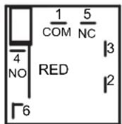
TIMER WITH BLINKING LED
The LED tells the technician in which mode the timer is operating. Rather than a jumper pin, this timer has a female spade connector that must be connected to terminal number 6.
- When this jumper is in place, the LED will blink at one-second intervals. This is the run mode.
- When the jumper is open, the LED will flash every 4/10ths second. This is the test mode and the timer will cycle every 55 seconds in test mode. Remember to replace the jumper when testing is complete. If the timer is left in test mode it will automatically reset to run mode.
When installing this timer into existing equipment, make sure to verify correct wiring of the timer. Some older equipment may require a wiring change. Check the yellow wire from the ice dispense switch (rocking chute) to the number two terminal of the timer. With this timer, the yellow wire leaves the ice dispense switch from the NC terminal of the switch.
TIMER WITH TEST PINS
The timer is equipped with test pins. This allows you to test the timer by removing the jumper between the two pins.
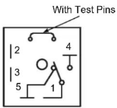
text_image
With Test Pins 2 3 5 1 4The timer is non-adjustable and is set to agitate the ice for three seconds every three and one half-hours. Activating the dispenser will reset the timer. After 3.5 hours of non-use the timer will energize the dispenser motor.
To check for correct function of the agitation timer, use the following procedure:
The agitation timer is located at the front of the dispenser in the control box, on the left side of the ice chute.
- Remove the jumper between the two pins.
- The timer will cycle every 55 seconds.
- If the timer does not cycle every 55 seconds, replace the timer.
- Replace jumper after testing.
Caution
Never operate with jumper removed. Damage will occur.
Section 4 Maintenance
Warning
Dispenser is not suitable for installation in an area where a water jet could be used and must not be cleaned by a water jet.
Disassembly
REMOVING THE FRONT PANEL
Warning
Electric Shock Hazard
Unplug unit before servicing or cleaning. The agitator is operated by a timer and can agitate at anytime.
- Shut off water to ice machine.
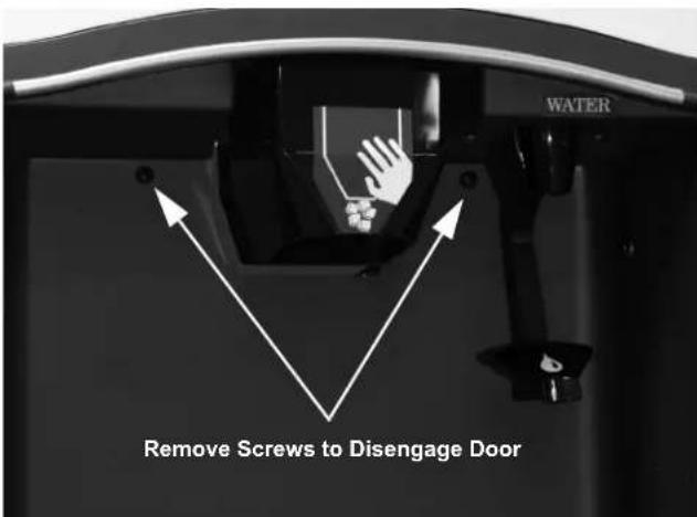
text_image
WATER Remove Screws to Disengage Door-
The 2 screws are retained by o-rings. Loosen the 2 screws with a Phillips screwdriver.
-
Hold the front panel of the dispenser on both sides, pull top forward to release top catch and then tilt the panel forward. The front panel will be resting on the catch hooks at the bottom of the panel.
-
SFA-191/291 ONLY – A water line is attached to the front panel. If complete removal is required, disconnect main water supply, relieve water pressure and remove water line from water valve.
-
Lift the front panel off the catch hooks and set the panel aside.
REMOVING THE DRAIN PAN
-
The drain pan is visible when the front panel of the dispenser is removed.
-
Loosen clamp and remove drain hose from drain pan.
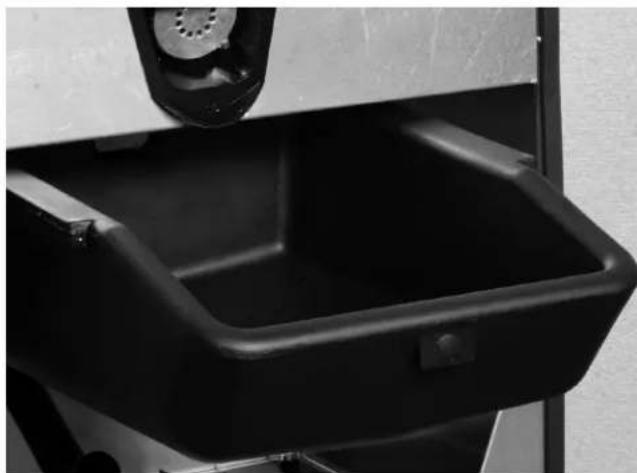
natural_image
Close-up of a black plastic waste bin with a mechanical component above it (no visible text or symbols)-
Slide the drain pan forward and pull out.
-
Remove scrap ice if any scrap ice has accumulated.
-
After cleaning, slide drain pan back into place.
DISASSEMBLING THE ROCKING CHUTE/DOOR & PADDLE WHEEL GUARD

Warning
Electric Shock Hazard
Unplug unit before servicing or cleaning.
- Remove the front panel from the dispenser. (See "Removing the Front Panel".)
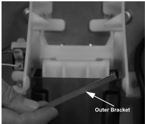
text_image
Outer Bracket- Remove outer bracket.
natural_image
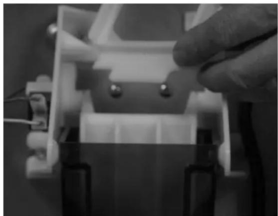
Close-up of a hand adjusting a small electronic component with wires and connectors (no visible text or symbols)- Remove door lock.
natural_image
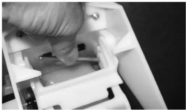
Close-up of a gloved hand inserting a plastic component into a white plastic housing (no text or symbols visible)- Lift up left end of door rod and pull rod out from right side of door.
natural_image
Close-up of a finger pressing down on a mechanical component (no visible text or symbols)-
Remove door.
-
Remove ice chute.
natural_image
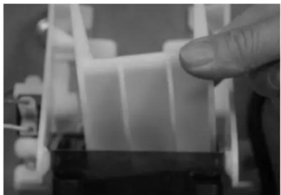
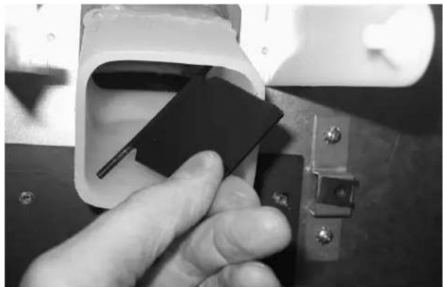
Close-up of a hand holding a small electronic component with a metallic bracket (no visible text or symbols)- Pull the paddle wheel guard from the holes inside the ice dispense snout.

text_image
Paddle Wheel Guard- Remove the paddle wheel guard from the ice dispense snout.
DISASSEMBLING THE DISPENSER PARTS FOR BIN CLEANING

Warning
Unplug unit before servicing or cleaning.
Ice dispenser bin contains moving parts that can move at any time and will cause injury if hands are in the way.
text_image
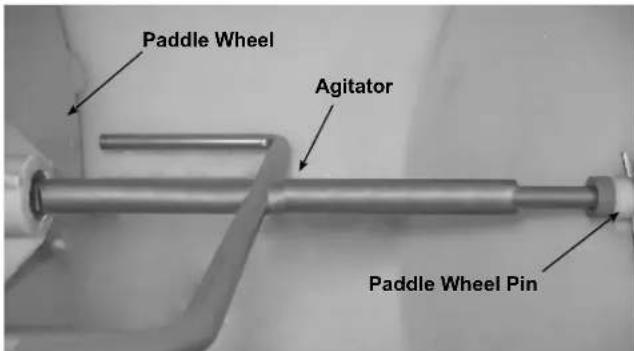
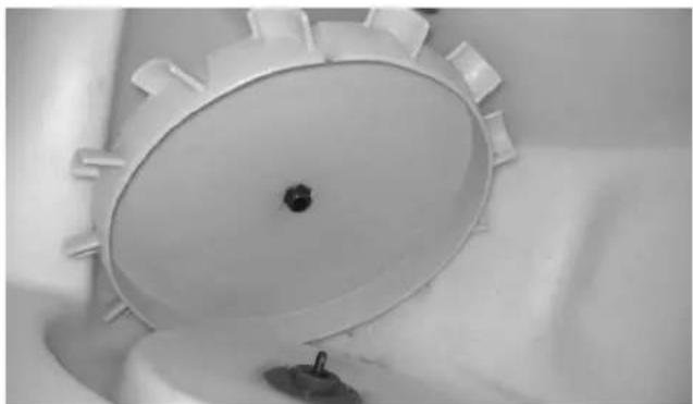
Paddle Wheel Agitator Paddle Wheel Pin- These parts will be removed: agitator pin, agitator and paddle wheel.
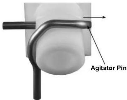
text_image
Agitator Pin- Pull on the hand-removable agitator pin until it is clear of the agitator bushing.
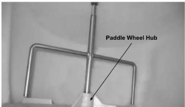
text_image
Paddle Wheel Hub- Push the agitator toward the back of the bin until the agitator is free of the paddle wheel hub. Remove the agitator by sliding to one side as you pull forward until the agitator shaft clears the bushing.
natural_image
Close-up of a white mechanical component with a central hole and radial grooves (no visible text or symbols)- Slide the paddle wheel from the motor shaft and remove.
Cleaning and Sanitizing MONTHLY SANITIZING PROCEDURE

Warning
Electric Shock Hazard
Unplug unit before servicing or cleaning.
- Remove the front panel, paddle wheel, ice chute and door assembly.
- Mix a solution of 3 ounces (100 ml) Manitowoc cleaner per 1 gallon (4 liters) plain tap water.
- Carefully clean all parts removed from inside the bin with this cleaner. Clean the dispenser bin, door assembly, and ice chute.
- Rinse all cleaned parts with fresh, running tap water.
- Mix a solution of 3 ounce (90 ml) Manitowoc sanitizer with 4 gallons (15 liters) plain tap water.
- Sanitize each part washed in the previous step with this sanitizer solution. Sanitize and re-assemble in this order:
Paddle wheel
Agitator
Paddle wheel pin
Ice chute assembly
Scrap ice tray
Front panel
- Do not rinse dispenser parts after they are sanitized. Allow parts to air dry.
- After all dispenser parts are replaced, restore power to the dispenser.
- Turn the ice machine on.
- Allow the ice machine to begin filling the dispenser.
- After three batches are in the dispenser, test the dispenser operation.
Assembly RE-INSTALLING THE PADDLE WHEEL GUARD
natural_image
Close-up of a hand inserting a black plastic clip into a white plastic housing (no text or symbols visible)When re-assembling the rocking chute/door, the paddle wheel guard is installed inside the ice dispense snout.
When the paddle wheel guard is placed in the snout, its top hinge is snapped into mounting holes on both sides of the snout.
When the paddle wheel guard is correctly installed, the paddle wheel guard will swing outward toward the front of the chute, allowing ice to flow out of the chute.
If incorrectly installed, the paddle wheel guard will not swing outward and ice delivery is blocked.
Correct Installation
text_image
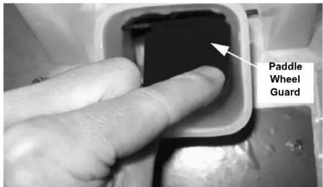
Paddle Wheel GuardIf you press your finger forward against the paddle wheel guard, the paddle wheel guard does not swing back open.
Removal of the Gearmotor
NOTE: The gearmotor does not have to be removed for cleaning/sanitizing.
Warning
Electric Shock Hazard
Unplug unit before servicing or cleaning.
- Remove the front panel from dispenser. (See "Removing the Front Panel".)
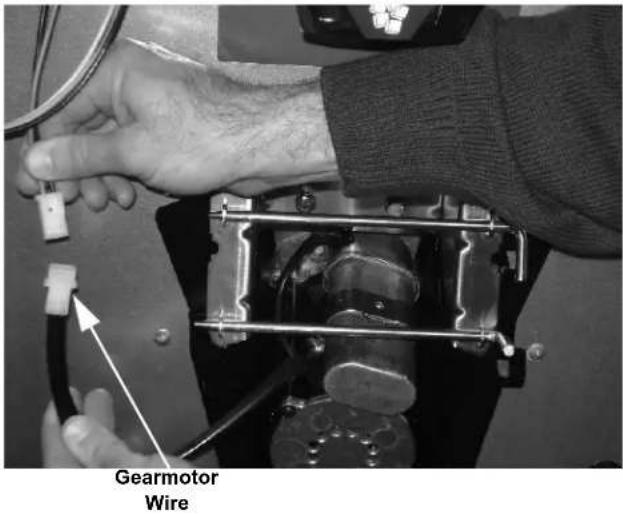
text_image
Gearmotor Wire- Unplug the gearmotor wire.
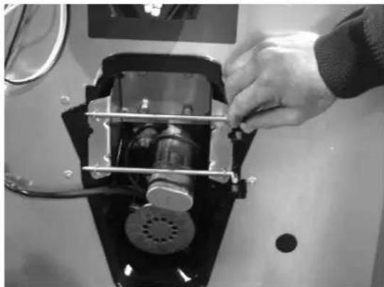
natural_image
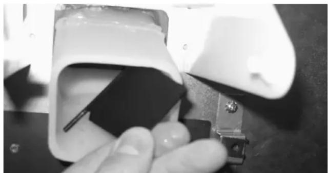
Close-up of a hand adjusting a mechanical component inside a container (no visible text or symbols)- Turn the two removal pins toward you.
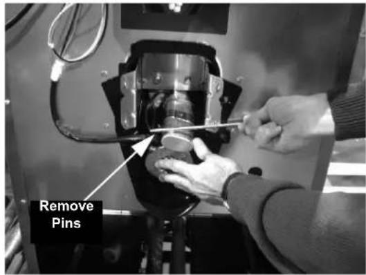
text_image
Remove Pins- Pull removal pins out to the right.
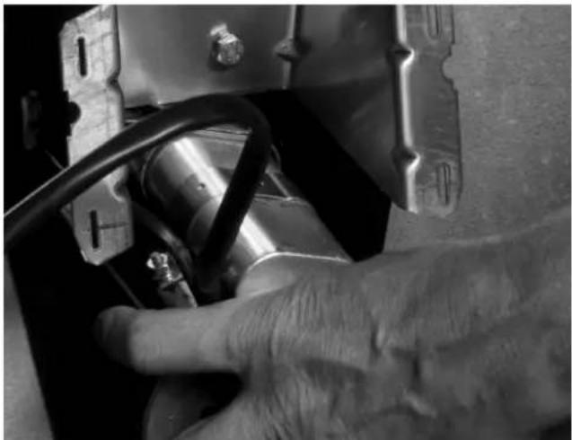
natural_image
Close-up of a hand adjusting a mechanical component with visible wiring and mounting brackets (no text or symbols)- Grasp the gearmotor as the second pin is removed. Pivot the gearmotor out of place.
Section 5 Customer Support
Checklist
If a problem arises during operation of your dispenser, follow the checklists below, before calling service. Routine adjustments and maintenance procedures are not covered by the warranty.
Warning
Unplug unit before servicing or cleaning. Ice dispenser bin contains parts that can move at any time and will cause injury if hands are in the way.
PROBLEM: ICE DOES NOT DISPENSE WHEN ROCKING CHUTE IS DEPRESSED
| Problem Possible Cause | To Correct | |
| Dispenser does not operate. No electrical power to dispenser. Plugged in? | ||
| Breaker tripped? | ||
| Check the cord and plug of the dispenser,Replace cord set if wire is broken. | ||
| Dispenser runs but does not dispense ice. | No ice in bin. Add ice to bin, have ice machine checked. | |
PROBLEM: DISPENSER CRUSHES ICE AS IT DISPENSES
| Problem Possible Cause | To Correct | |
| Dispenser crushes ice as it dispenses. The | ice in the bin is not the proper size and type. | Replace with acceptable ice. |
| Is the ice being used a full size piece of ice, i.e., are cubes full, not shallow, etc.? | Adjust ice machine cube size. Refer to ice machine Installation, Use and Care manual for procedure. |
PROBLEM: ICE CONTINUES TO DISPENSE OR DISPENSES BY ITSELF
| Problem Possible Cause | To Correct | |
| Dispenser agitates every 55 seconds. No | Jumper on the timer. Call for Service. | |
| Does ice continue to dispense after the cup has been pulled away? | Does the gearmotor continue to run during this time? | Call for Service. |
| Does the ice dispense by itself without anyone around the dispenser? | Does the dispenser do this at regular intervals? | Call for Service. |
Ice Machine Warranty
Warranty
For warranty information visit:
www.manitowocice.com/Service/Warranty
• Warranty Coverage Information
- Warranty Registration
- Warranty Verification
Warranty coverage begins the day the ice machine is installed.
WARRANTY REGISTRATION
Completing the warranty registration process is a quick and easy way to protect your investment.
Scan the QR code with your smart device or enter the link in a web browser to complete your warranty registration.

text_image
QR code image containing encoded data, no visible human-readable textWWW.MANITOWOCICE.COM/SERVICE/WARRANTY#WARRANTY-REGISTRATION
Registering your product insures warranty coverage and streamlines the process if any warranty work is required.
THIS PAGE INTENTIONALLY LEFT BLANK
Table des matières
KIT DE DÉFLECTEUR INCLUS
APPROVISIONNEMENT D'EAU
natural_image
Close-up of a black plastic waste bin with a metal hook inserted, no visible text or symbolstext_image
Support externe- Retirer le support externe.

natural_image
Close-up of a hand adjusting a small electronic component with wires and components (no visible text or symbols)- Retirer la serrure de porte.

natural_image
Close-up of a gloved hand inserting a small electronic component into a white plastic housing (no visible text or symbols)natural_image
Close-up of a finger pressing down on a mechanical component (no visible text or symbols)natural_image
Close-up of a hand holding a white electronic device with a black plastic component inserted, no visible text or symbols.natural_image
Close-up of a white plastic water dispenser with a central dot and spout, placed on a surface (no text or symbols visible)natural_image
Close-up of a hand inserting a black plastic clip into a white electronic device component (no visible text or symbols)natural_image
Close-up of hands operating a mechanical device with wires and connectors (no visible text or symbols)natural_image
Close-up of a hand adjusting a mechanical component with metal brackets (no visible text or symbols)natural_image
Close-up of a hand adjusting a mechanical component with visible wiring and mounting brackets (no text or symbols)text_image
QR code image containing encoded data, no visible human-readable textWWW.MANITOWOCICE.COM/SERVICE/WARRANTY#WARRANTY-REGISTRATION
2110 South 26TH Street, Manitowoc WI.
54220
800-545-5720
WWW>MANITOWOCICE.COM